
2 Installation and maintenance instructions 0020244997_07
Installation and maintenance
instructions
Contents
1 Safety .................................................................... 4
1.1 Intended use.......................................................... 4
1.2 Qualification........................................................... 4
1.3 General safety information .................................... 4
1.4 Regulations (directives, laws, standards) .............. 6
1.5 List of relevant standards for Great Britain and
Ireland.................................................................... 6
2 Guarantee and Customer Service...................... 7
3 Technical data...................................................... 8
4 Notes on the documentation ............................ 15
5 Product description........................................... 15
5.1 CE marking.......................................................... 15
5.2 Energy Saving Trust Endorsed Products ............ 15
5.3 Hot Water Association ......................................... 15
5.4 Information on the identification plate.................. 15
5.5 Serial number ...................................................... 16
5.6 Product design..................................................... 16
5.7 Safety Devices..................................................... 17
6 Set-up.................................................................. 18
6.1 Checking the scope of delivery............................ 18
6.2 Dimensions.......................................................... 18
6.3 Installation site..................................................... 19
6.4 Minimum clearances............................................ 19
6.5 Compartment Ventilation ..................................... 19
6.6 Air/flue pipe.......................................................... 19
6.7 Using the installation template............................. 22
6.8 Wall-mounting the product................................... 22
6.9 Removing/installing the front casing.................... 23
6.10 Removing/installing the side section ................... 23
7 Installation.......................................................... 24
7.1 Installation requirements ..................................... 24
7.2 Preparing for installation...................................... 24
7.3 Descaling the water ............................................. 24
7.4 Installing the gas connection ............................... 24
7.5 Checking the gas line for leak-tightness.............. 25
7.6 Installing the hot and cold water connection........ 25
7.7 Connecting the domestic hot water cylinder........ 25
7.8 Connecting the heating flow and heating
return ................................................................... 25
7.9 Installing the drain pipe on the expansion relief
valve .................................................................... 25
7.10 Connecting the condensate discharge pipe ........ 25
7.11 Flue installation.................................................... 28
7.12 Electrical installation ............................................ 28
8 Operation............................................................ 31
8.1 Operating concept ............................................... 31
8.2 Calling up the installer level................................. 31
8.3 Live Monitor (status codes) ................................. 31
8.4 Setting the hot water temperature ....................... 31
9 Start-up ............................................................... 32
9.1 Carrying out the initial start-up............................. 32
9.2 Switching the product on and off ......................... 32
9.3 Running the installation assistants ...................... 32
9.4 Restarting the installation assistants ................... 32
9.5 Test programmes................................................. 32
9.6 Performing a gas family check ............................ 33
9.7 Using check programmes.................................... 33
9.8 Checking and treating the heating water/filling
and supplementary water .................................... 33
9.9 Filling the condensate trap .................................. 34
9.10 Preventing low water pressure ............................ 34
9.11 Flushing the heating installation for the first
time ("cold") ......................................................... 34
9.12 Filling the heating installation .............................. 35
9.13 Purging the heating installation ........................... 35
9.14 Filling and purging the hot water system ............. 36
9.15 Gas inspection..................................................... 36
9.16 Thoroughly flushing the heating installation
("hot")................................................................... 38
9.17 Checking leak-tightness ...................................... 38
10 Adapting the unit to the heating
installation.......................................................... 39
10.1 Burner anti-cycling time ....................................... 39
10.2 Setting the maintenance interval ......................... 39
10.3 Setting the pump output....................................... 40
10.4 Setting the bypass valve...................................... 40
11 Handing over to the end user........................... 41
12 Inspection and maintenance ............................ 42
12.1 Complete Service Interval Record section .......... 42
12.2 Using original seals.............................................. 42
12.3 Inspection and maintenance................................ 42
12.4 Preparing the maintenance work......................... 42
12.5 Function menu..................................................... 42
12.6 Electronics self-test.............................................. 42
12.7 Checking the electrical plug connections ............ 42
12.8 Removing the compact thermal module .............. 42
12.9 Cleaning the heat exchanger............................... 43
12.10 Checking the burner ............................................ 43
12.11 Cleaning the condensate trap.............................. 44
12.12 Cleaning the strainer in the cold water inlet......... 44
12.13 Installing the compact thermal module ................ 44
12.14 Draining the product ............................................ 44
12.15 Checking the pre-charge pressure for the
internal expansion vessel .................................... 44
12.16 Checking the filling pressure of the heating
installation............................................................ 45
12.17 Checking the quality of the heating water............ 45
12.18 Completing inspection and maintenance work .... 45
12.19 Checking the product for leak-tightness .............. 45
13 Troubleshooting ................................................ 45
13.1 Checking service messages................................ 45
13.2 Eliminating faults.................................................. 45
13.3 Calling up and clearing the fault memory ............ 45
13.4 Resetting parameters to factory settings ............. 45
13.5 Preparing the repair work .................................... 45

0020244997_07 Installation and maintenance instructions 3
13.6 Replacing defective components......................... 46
13.7 Completing repair work........................................ 50
13.8 Checking the product for leak-tightness .............. 50
14 Decommissioning.............................................. 50
14.1 Temporarily decommissioning the product.......... 50
14.2 Permanently decommissioning the product......... 50
15 Recycling and disposal..................................... 50
Appendix ............................................................................ 51
A Inspection and maintenance work................... 51
B Installer level – Overview .................................. 52
C Overview of diagnostics codes........................ 54
D Status codes – Overview .................................. 59
E Overview of fault codes .................................... 60
F Check programmes – Overview ....................... 63
G Function menu – Overview ............................... 63
H Wiring diagrams................................................. 64
H.1 Wiring diagram, product for heating mode
only, 12 - 35 kW................................................... 64
H.2 Wiring diagram, product for heating mode
only, ≥ 37 kW....................................................... 66
H.3 Wiring diagram, product with integrated
domestic hot water generation, 12–35 kW .......... 68
H.4 Wiring diagram, product with integrated
domestic hot water generation, ≥ 37 kW ............. 70
I Commissioning Checklist................................. 72
J Commissioning Flow Chart .............................. 76
Index ................................................................................... 77

4 Installation and maintenance instructions 0020244997_07
1 Safety
1.1 Intended use
The product is intended as a heat generator
for sealed heating installations and for do-
mestic hot water generation.
Improper use of any kind is prohibited.
Intended use also includes the following:
– use of the product only in mobile homes
that are made, transported once and per-
manently situated in Great Britain and Ire-
land. After the transportation of the mo-
bile home to its destination the complete
product must be checked for leak-tightness
again
– validity of the product only for Great Britain
and Ireland and for the gas types in Great
Britain and Ireland as listed on the data
plate
– Installing and operating the product only
in conjunction with accessories for the
air/flue pipe which are listed in the other
applicable documents and comply with the
type of unit
– Using the product while observing the ac-
companying operating, installation and
maintenance instructions for the product
along with all other components of the in-
stallation
– Installing and setting up the product while
observing the product and system ap-
proval
– Observing all inspection and maintenance
conditions listed in the instructions
– Installing while observing the IP code
The following is classed as improper use:
– Using the product in vehicles, such as mo-
bile homes or caravans. Units that are not
classed as vehicles are those that are in-
stalled in a fixed and permanent location
(known as "fixed installation").
– Any direct use in industrial or commercial
processes
– Any use other than those described in
these instructions and any use that goes
beyond what is described here
1.2 Qualification
The person carrying out the work described
here must have completed professional train-
ing. The competent person must demon-
strably have all of the knowledge, skills and
capabilities that are required in order to carry
out the work mentioned below.
The following work must only be carried out
by competent persons who are sufficiently
qualified to do so:
– Set-up
– Dismantling
– Installation
– Start-up
– Inspection and maintenance
– Repair
– Decommissioning
▶ Proceed in accordance with current tech-
nology.
▶ Use the correct tool.
The above-mentioned work must always only
be carried out by persons with sufficient qual-
ifications.
This product can be used by children over
eight years old and also by persons with lim-
ited physical, sensory or mental capabilities
or insufficient experience and/or knowledge if
they are supervised or have been provided
with instructions on how to safely use the
product, and they understand the risks res-
ulting from using the product. Children must
not play with the product. Cleaning and user
maintenance work must not be carried out by
children unless they are supervised.
1.3 General safety information
The following sections convey important
safety information. It is essential to read and
observe this information in order to prevent
risk of death, risk of injury, material damage
or environmental damage.
1.3.1 Gas
If you smell gas:
▶ Avoid rooms that smell of gas.
▶ If possible, open doors and windows fully
and ensure adequate ventilation.
▶ Do not use naked flames (e.g. lighters,
matches).

0020244997_07 Installation and maintenance instructions 5
▶ Do not smoke.
▶ Do not use any electrical switches, mains
plugs, doorbells, telephones or other com-
munication systems in the building.
▶ Close the emergency control valve or the
main isolator.
▶ If possible, close the gas stopcock on the
product.
▶ Warn other occupants in the building by
yelling or banging on doors or walls.
▶ Leave the building immediately and ensure
that others do not enter the building.
▶ Alert the police and fire brigade, and in-
form the emergency service department of
the gas supply company as soon as you
are outside the building.
1.3.2 Flue gas
Flue gases may cause poisoning, while hot
flue gases may also cause burns. Flue gases
must therefore never be allowed to escape
uncontrollably.
What to do if you smell flue gas in the prop-
erty:
▶ Open all accessible doors and windows
fully to provide ventilation.
▶ Switch off the product.
▶ Check the flue gas routes in the product
and the flue gas diversions.
To prevent flue gas exit:
▶ Only operate the product if the air/flue pipe
has been completely installed.
▶ With the exception of short periods for
testing purposes, only operate the product
when the front casing is installed and
closed.
▶ In order to operate the product, ensure that
the condensate siphon is always full.
– Water seal level for units with condens-
ate siphon (third-party accessory):
≥ 200 mm
To ensure that the seals are not damaged:
▶ Instead of grease, use only water or com-
mercially available soft soap to aid installa-
tion.
1.3.3 Air supply
Unsuitable or insufficient combustion and
room air may lead to material damage, but
also to life-threatening situations.
To ensure that the combustion air supply is
sufficient during open-flued operation:
▶ Ensure that the air supply to the product's
installation room is permanently unobstruc-
ted and sufficient in accordance with the
relevant ventilation requirements. This also
applies, in particular, for cupboard installa-
tions.
To prevent corrosion on the product and in
the flue system:
▶ Ensure that the combustion air supply is
free from sprays, solvents, chlorinated
cleaning agents, paint, adhesives, am-
monia compounds, dust or similar sub-
stances.
▶ Ensure that no chemical substances are
stored at the installation site.
▶ If you are installing the product in
hairdressing salons, painter's or joiner's
workshops, cleaning businesses or similar
locations, choose a separate installation
room in which the room air is technically
free of chemical substances.
1.3.4 Electricity
The power supply terminals L and N remain
live.
To prevent electric shocks, proceed as fol-
lows before working on the product:
▶ Disconnect the product from the power
supply by switching off all power supplies
at all poles (electrical partition with a con-
tact gap of at least 3 mm, e.g. fuse or cir-
cuit breaker) or remove the mains plug (if
present).
▶ Secure against being switched back on
again.
▶ Wait at least three minutes until the con-
densers have discharged.
▶ Check that there is no voltage.
1.3.5 Weight
To prevent injuries when transporting the
product:
▶ Make sure that the product is transported
by at least two people.
To prevent material damage to the flexible
gas pipe:
▶ Never suspend the compact thermal
module on the flexible gas pipe.

6 Installation and maintenance instructions 0020244997_07
1.3.6 Explosive and flammable substances
To prevent explosions and fire:
▶ Do not use the product in storage rooms
that contain explosive or flammable sub-
stances (such as petrol, paper or paint).
1.3.7 High temperatures
To prevent burns:
▶ Only carry out work on components once
they have cooled down.
To prevent material damage that is caused
by heat transfer:
▶ Only solder connectors if the connectors
are not yet screwed to the service valves.
1.3.8 Heating water
Both unsuitable heating water and air in the
heating water may cause material damage to
the product and in the heat generator circuit.
▶ Check the quality of the heating water.
(→ Page 33)
▶ If you use non-diffusion-tight plastic pipes
in the heating installation, ensure that no
air gets into the heat generator circuit.
1.3.9 Neutralisation device
To prevent contamination of the waste water:
▶ Check whether a neutralising unit must
be installed in accordance with national
regulations.
▶ Observe local regulations on neutralising
condensate.
1.3.10 Frost
To prevent material damage:
▶ Do not install the product in rooms prone
to frost.
1.3.11 Safety devices
▶ Install the necessary safety devices in the
installation.
1.3.12 Risk of death from leaks if the
product is installed below ground
level
Liquid gas accumulates at floor level. If the
product is installed below ground level, liquid
gas may accumulate at floor level if there
are any leaks. In this case, there is a risk of
explosion.
▶ Make sure that liquid gas cannot escape
from the product or the gas pipe under any
circumstances.
1.3.13 Risk of material damage caused by
leak detection sprays and fluids
Leak detection sprays and fluids block the
filter for the mass flow sensor on the Venturi,
thereby destroying the mass flow sensor.
▶ During repair work, do not apply any leak
detection sprays or fluids to the covering
cap on the filter for the Venturi.
1.3.14 Risk of damage to the flexible gas
pipe
The corrugated gas pipe may become dam-
aged if weight is placed on it.
▶ Do not suspend the compact thermal
module on the flexible gas pipe, for
example during maintenance work.
1.4 Regulations (directives, laws,
standards)
▶
Observe the national regulations, stand-
ards, directives, ordinances and laws.
1.5 List of relevant standards for Great
Britain and Ireland
▶ Observe the national regulations, stand-
ards, directives, ordinances and laws.
You can find a list of relevant standards at:
https://www.vaillant.co.uk/standards

0020244997_07 Installation and maintenance instructions 7
2 Guarantee and Customer Service
Thank you for installing a new Vaillant appliance in your home.
Vaillant appliances are manufactured to the very highest standard so we are pleased to offer our
customers a comprehensive guarantee.
To maintain your guarantee, the boiler must be serviced annually by a competent person who
holds the required qualifications in accordance with the rules in force of the country where the
product is installed and in accordance with the manufactures recommendations.
We recommend you complete your guarantee registration as soon as possible.
Guarantee Registration
Sales Support:
Telephone: 0345 602 0262
Technical Enquiries:
Telephone: 0344 693 3133
Email: technical@vaillant.co.uk
General Enquiries:
Telephone: 0345 602 2922
Training Enquiries:
Telephone: 0345 601 8885
Email: training.enquiriesuk@vaillant-group.com
Spares Enquiries:
Telephone: 01773 596 615
To register your Vaillant appliance visit:
https://self-service.vaillant.co.uk/warranty-registration
Vaillant is a licensed member of the Benchmark Scheme. Benchmark places responsibilities on both manufacturers and installers.
The purpose is to ensure that customers are provided with the correct equipment for their needs, that it is installed, commissioned
and serviced in accordance with the manufacturer’s instructions by a competent person approved at the time by the Health and
Safety Executive and that it meets the requirements of the appropriate Building Regulations.
The Benchmark Checklist can be used to demonstrate compliance with Building Regulations and should be provided to the customer
for future reference.
Installers are required to carry out installation, commissioning and servicing work in accordance with the Benchmark Code of
Practice which is available from the Heating and Hotwater Industry Council who manage and promote the Scheme.
Benchmark is managed and promoted by the Heating and Hotwater Industry Council.

8 Installation and maintenance instructions 0020244997_07
3 Technical data
Technical data – General
VU 126/5-
5 (H-GB)
ecoTEC plus
612
VU 156/5-
5 (H-GB)
ecoTEC plus
615
VU 186/5-
5 (H-GB)
ecoTEC plus
618
VU 186/5-
5 (P-GB)
ecoTEC plus
618
VU 246/5-
5 (H-GB)
ecoTEC plus
624
VU 306/5-
5 (H-GB)
ecoTEC plus
630
Designated country (des-
ignation in accordance
with ISO 3166)
GB (Great
Britain), IE
(Ireland)
GB (Great
Britain), IE
(Ireland)
GB (Great
Britain), IE
(Ireland)
GB (Great
Britain), IE
(Ireland)
GB (Great
Britain), IE
(Ireland)
GB (Great
Britain), IE
(Ireland)
Approved gas boiler cat-
egories
I
2H
I
2H
II
2H3P
II
2H3P
II
2H3P
II
2H3P
Gas connection, boiler
side
15 mm 15 mm 15 mm 15 mm 15 mm 15 mm
Flow/return heating con-
nections, boiler side
22 mm 22 mm 22 mm 22 mm 22 mm 22 mm
Domestic hot and cold
water connection, boiler
side
– – – – – –
Expansion relief valve
connection pipe (min.)
15 mm 15 mm 15 mm 15 mm 15 mm 15 mm
Air/flue gas connection
60/100 mm 60/100 mm 60/100 mm 60/100 mm 60/100 mm 60/100 mm
Condensate drain pipe-
work (min.)
19 mm 19 mm 19 mm 19 mm 19 mm 19 mm
G20 natural gas flow
pressure
2.0 kPa
(20.0 mbar)
2.0 kPa
(20.0 mbar)
2.0 kPa
(20.0 mbar)
– 2.0 kPa
(20.0 mbar)
2.0 kPa
(20.0 mbar)
G31 propane gas flow
pressure
– – – 3.7 kPa
(37.0 mbar)
– –
Gas flow rate at 15 °C
and 1013 mbar (based
on domestic hot water
generation, if applicable),
G20
1.3 m³/h 1.7 m³/h 2.0 m³/h – 2.6 m³/h 3.7 m³/h
Gas flow rate at 15 °C
and 1013 mbar (based
on domestic hot water
generation, if applicable),
G31
– – – 1.5 kg/h – –
Min. flue gas mass flow
rate (G20)
1.44 g/s 1.44 g/s 1.80 g/s – 2.47 g/s 2.78 g/s
Min. flue gas mass flow
rate (G31)
– – – 2.40 g/s – –
Max. flue gas mass flow
rate
5.6 g/s 7.0 g/s 8.4 g/s 8.4 g/s 11.1 g/s 13.9 g/s
Min. flue gas temperature
40 ℃ 40 ℃ 40 ℃ 40 ℃ 40 ℃ 40 ℃
Max. flue gas temperat-
ure
70 ℃ 70 ℃ 70 ℃ 70 ℃ 70 ℃ 70 ℃
Approved gas boiler
types
C13, C33,
C43, C53
C13, C33,
C43, C53
C13, C33,
C43, C53
C13, C33,
C43, C53
C13, C33,
C43, C53
C13, C33,
C43, C53
30% efficiency
109.3 % 109.3 % 109.6 % 108.5 % 109.5 % 109.4 %
NOx class
6 6 6 6 6 6
Test symbol/registration
no.
CE‑
0085CM0320
CE‑
0085CM0320
CE‑
0085CM0320
CE‑
0085CM0320
CE‑
0085CM0320
CE‑
0085CM0320
SAP 2009/2012 annual
efficiency (%)
89.3 % 89.2 % 89.6 % 89.6 % 89.6 % 89.5 %
Boiler dimension, width
440 mm 440 mm 440 mm 440 mm 440 mm 440 mm
Boiler dimension, height
720 mm 720 mm 720 mm 720 mm 720 mm 720 mm
Boiler dimension, depth
338 mm 338 mm 338 mm 338 mm 338 mm 372 mm
Mounting weight
36 kg 36 kg 36 kg 36 kg 37 kg 38 kg

0020244997_07 Installation and maintenance instructions 9
VU 306/5-
5 (P-GB)
ecoTEC plus
630
VU 386/5-
5 (H-GB)
ecoTEC plus
637
VUW 196/5-
5 (H-GB)
ecoTEC plus
825
VUW 246/5-
5 (H-GB)
ecoTEC plus
832
VUW 246/5-
5 (P-GB)
ecoTEC plus
832
VUW 306/5-
5 (H-GB)
ecoTEC plus
835
Designated country (des-
ignation in accordance
with ISO 3166)
GB (Great
Britain), IE
(Ireland)
GB (Great
Britain), IE
(Ireland)
GB (Great
Britain), IE
(Ireland)
GB (Great
Britain), IE
(Ireland)
GB (Great
Britain), IE
(Ireland)
GB (Great
Britain), IE
(Ireland)
Approved gas boiler cat-
egories
II
2H3P
II
2H3P
II
2H3P
II
2H3P
II
2H3P
II
2H3P
Gas connection, boiler
side
15 mm 15 mm 15 mm 15 mm 15 mm 15 mm
Flow/return heating con-
nections, boiler side
22 mm 22 mm 22 mm 22 mm 22 mm 22 mm
Domestic hot and cold
water connection, boiler
side
– – G 3/4″ G 3/4″ G 3/4″ G 3/4″
Expansion relief valve
connection pipe (min.)
15 mm 15 mm 15 mm 15 mm 15 mm 15 mm
Air/flue gas connection
60/100 mm 60/100 mm 60/100 mm 60/100 mm 60/100 mm 60/100 mm
Condensate drain pipe-
work (min.)
19 mm 19 mm 19 mm 19 mm 19 mm 19 mm
G20 natural gas flow
pressure
– 2.0 kPa
(20.0 mbar)
2.0 kPa
(20.0 mbar)
2.0 kPa
(20.0 mbar)
– 2.0 kPa
(20.0 mbar)
G31 propane gas flow
pressure
3.7 kPa
(37.0 mbar)
– – – 3.7 kPa
(37.0 mbar)
–
Gas flow rate at 15 °C
and 1013 mbar (based
on domestic hot water
generation, if applicable),
G20
– 4.1 m³/h 2.7 m³/h 3.4 m³/h – 3.8 m³/h
Gas flow rate at 15 °C
and 1013 mbar (based
on domestic hot water
generation, if applicable),
G31
2.4 kg/h – – – 2.5 kg/h –
Min. flue gas mass flow
rate (G20)
– 3.05 g/s 1.80 g/s 2.47 g/s – 2.78 g/s
Min. flue gas mass flow
rate (G31)
4.08 g/s – – – 2.90 g/s –
Max. flue gas mass flow
rate
13.9 g/s 17.4 g/s 8.4 g/s 11.1 g/s 11.1 g/s 16.2 g/s
Min. flue gas temperature
40 ℃ 40 ℃ 40 ℃ 40 ℃ 40 ℃ 40 ℃
Max. flue gas temperat-
ure
70 ℃ 70 ℃ 70 ℃ 70 ℃ 70 ℃ 70 ℃
Approved gas boiler
types
C13, C33,
C43, C53
C13, C33,
C43, C53
C13, C33,
C43, C53
C13, C33,
C43, C53
C13, C33,
C43, C53
C13, C33,
C43, C53
30% efficiency
108 % 109.3 % 109.6 % 109.5 % 108 % 109.4 %
NOx class
6 6 6 6 6 6
Test symbol/registration
no.
CE‑
0085CM0320
CE‑
0085CM0320
CE‑
0085CM0320
CE‑
0085CM0320
CE‑
0085CM0320
CE‑
0085CM0320
SAP 2009/2012 annual
efficiency (%)
89.7 % 89.5 % 89.5 % 89.5 % 89.5 % 89.4 %
Boiler dimension, width
440 mm 440 mm 440 mm 440 mm 440 mm 440 mm
Boiler dimension, height
720 mm 720 mm 720 mm 720 mm 720 mm 720 mm
Boiler dimension, depth
372 mm 406 mm 338 mm 338 mm 338 mm 372 mm
Mounting weight
38 kg 43 kg 36 kg 37 kg 37 kg 41 kg

10 Installation and maintenance instructions 0020244997_07
VUW 286/5-
5 (H-GB)
ecoTEC plus
838
Designated country (des-
ignation in accordance
with ISO 3166)
GB (Great
Britain), IE
(Ireland)
Approved gas boiler cat-
egories
II
2H3P
Gas connection, boiler
side
15 mm
Flow/return heating con-
nections, boiler side
22 mm
Domestic hot and cold
water connection, boiler
side
G 3/4″
Expansion relief valve
connection pipe (min.)
15 mm
Air/flue gas connection
60/100 mm
Condensate drain pipe-
work (min.)
19 mm
G20 natural gas flow
pressure
2.0 kPa
(20.0 mbar)
G31 propane gas flow
pressure
–
Gas flow rate at 15 °C
and 1013 mbar (based
on domestic hot water
generation, if applicable),
G20
4.2 m³/h
Gas flow rate at 15 °C
and 1013 mbar (based
on domestic hot water
generation, if applicable),
G31
–
Min. flue gas mass flow
rate (G20)
3.05 g/s
Min. flue gas mass flow
rate (G31)
–
Max. flue gas mass flow
rate
17.9 g/s
Min. flue gas temperature
40 ℃
Max. flue gas temperat-
ure
70 ℃
Approved gas boiler
types
C13, C33,
C43, C53
30% efficiency
109.4 %
NOx class
6
Test symbol/registration
no.
CE‑
0085CM0320
SAP 2009/2012 annual
efficiency (%)
89.4 %
Boiler dimension, width
440 mm
Boiler dimension, height
720 mm
Boiler dimension, depth
406 mm
Mounting weight
44 kg

0020244997_07 Installation and maintenance instructions 11
Technical data – G20 power/loading G20
VU 126/5-
5 (H-GB)
ecoTEC plus
612
VU 156/5-
5 (H-GB)
ecoTEC plus
615
VU 186/5-
5 (H-GB)
ecoTEC plus
618
VU 246/5-
5 (H-GB)
ecoTEC plus
624
VU 306/5-
5 (H-GB)
ecoTEC plus
630
VU 386/5-
5 (H-GB)
ecoTEC plus
637
Nominal heat output
range P at 50/30 °C
3.3 to 13.2 kW 3.3 to 16.7 kW 4.1 to 20.0 kW 5.7 to 26.4 kW 6.4 to 32.8 kW 7.1 to 40.5 kW
Nominal heat output
range P at 80/60 °C
3.0 to 12.2 kW 3.0 to 15.2 kW 3.8 to 18.2 kW 5.2 to 24.4 kW 5.8 to 30.4 kW 6.4 to 37.6 kW
Maximum heat output
for domestic hot water
generation
12.2 kW 15.2 kW 18.2 kW 24.4 kW 30.4 kW 37.6 kW
Maximum heat input for
domestic hot water gen-
eration
12.4 kW 15.5 kW 18.9 kW 24.7 kW 30.9 kW 38.1 kW
Maximum heat input,
heating side
12.4 kW 15.5 kW 18.6 kW 24.7 kW 30.9 kW 38.1 kW
Minimum heat input
3.2 kW 3.2 kW 4.0 kW 5.5 kW 6.2 kW 6.8 kW
Heating adjustment range
3 to 12 kW 3 to 15 kW 4 to 19 kW 5 to 24 kW 6 to 30 kW 6 to 38 kW
Nominal heat input ef-
ficiency (stationary) at
40/30 °C
108.0 % 109.0 % 109.0 % 108.0 % 107.0 % 107.0 %
Nominal heat input ef-
ficiency (stationary) at
50/30 °C
106.0 % 108.0 % 108.0 % 107.0 % 106.0 % 106.0 %
Nominal heat input ef-
ficiency (stationary) at
60/40 °C
101.0 % 101.0 % 101.0 % 101.0 % 101.0 % 101.0 %
Nominal heat input ef-
ficiency (stationary) at
80/60 °C
99 % 98.0 % 98.0 % 98.0 % 98.0 % 98.0 %
VUW 196/5-
5 (H-GB)
ecoTEC plus
825
VUW 246/5-
5 (H-GB)
ecoTEC plus
832
VUW 306/5-
5 (H-GB)
ecoTEC plus
835
VUW 286/5-
5 (H-GB)
ecoTEC plus
838
Nominal heat output
range P at 50/30 °C
4.1 to 20.8 kW 5.7 to 26.4 kW 6.4 to 32.8 kW 7.1 to 30.9 kW
Nominal heat output
range P at 80/60 °C
3.8 to 19.3 kW 5.2 to 24.4 kW 5.8 to 30.4 kW 6.5 to 28.6 kW
Maximum heat output
for domestic hot water
generation
24.4 kW 31.8 kW 34.0 kW 38.7 kW
Maximum heat input for
domestic hot water gen-
eration
24.7 kW 32.2 kW 34.7 kW 39.2 kW
Maximum heat input,
heating side
19.6 kW 24.7 kW 30.9 kW 28.9 kW
Minimum heat input
4.0 kW 5.5 kW 6.2 kW 6.8 kW
Heating adjustment range
4 to 19 kW 5 to 24 kW 6 to 30 kW 6 to 29 kW
Nominal heat input ef-
ficiency (stationary) at
40/30 °C
108.0 % 108.0 % 107.0 % 107.0 %
Nominal heat input ef-
ficiency (stationary) at
50/30 °C
106.0 % 107.0 % 106.0 % 107.0 %
Nominal heat input ef-
ficiency (stationary) at
60/40 °C
101.0 % 101.0 % 101.0 % 101.0 %
Nominal heat input ef-
ficiency (stationary) at
80/60 °C
98.0 % 98.0 % 98.0 % 98.0 %

12 Installation and maintenance instructions 0020244997_07
Technical data – Power/loading G31
VU 186/5-
5 (P-GB)
ecoTEC plus
618
VU 306/5-
5 (P-GB)
ecoTEC plus
630
VUW 246/5-
5 (P-GB)
ecoTEC plus
832
Nominal heat output
range P at 50/30 °C
5.4 to 19.4 kW 9.4 to 31.9 kW 6.5 to 25.5 kW
Nominal heat output
range P at 80/60 °C
5.0 to 18.2 kW 8.5 to 30.4 kW 6.0 to 24.4 kW
Maximum heat output
for domestic hot water
generation
18.3 kW 30.4 kW 31.8 kW
Maximum heat input for
domestic hot water gen-
eration
18.6 kW 30.9 kW 32.2 kW
Maximum heat input,
heating side
18.6 kW 30.9 kW 24.7 kW
Minimum heat input
5.3 kW 9.0 kW 6.4 kW
Nominal heat input ef-
ficiency (stationary) at
40/30 °C
104.0 % 104.0 % 104.0 %
Nominal heat input ef-
ficiency (stationary) at
50/30 °C
104.0 % 103.0 % 103.0 %
Nominal heat input ef-
ficiency (stationary) at
60/40 °C
101.0 % 101.0 % 101.0 %
Nominal heat input ef-
ficiency (stationary) at
80/60 °C
98.0 % 98.0 % 98.0 %
Technical data – Heating
VU 126/5-
5 (H-GB)
ecoTEC plus
612
VU 156/5-
5 (H-GB)
ecoTEC plus
615
VU 186/5-
5 (H-GB)
ecoTEC plus
618
VU 186/5-
5 (P-GB)
ecoTEC plus
618
VU 246/5-
5 (H-GB)
ecoTEC plus
624
VU 306/5-
5 (H-GB)
ecoTEC plus
630
Maximum flow temperat-
ure
85 ℃ 85 ℃ 85 ℃ 85 ℃ 85 ℃ 85 ℃
Max. flow temperature
adjustment range (default
setting: 75 °C)
30 to 80 ℃ 30 to 80 ℃ 30 to 80 ℃ 30 to 80 ℃ 30 to 80 ℃ 30 to 80 ℃
Permissible operating
pressure
0.25 MPa
(2.50 bar)
0.25 MPa
(2.50 bar)
0.25 MPa
(2.50 bar)
0.25 MPa
(2.50 bar)
0.25 MPa
(2.50 bar)
0.25 MPa
(2.50 bar)
Minimum pressure for
full operation
0.08 MPa
(0.80 bar)
0.08 MPa
(0.80 bar)
0.08 MPa
(0.80 bar)
0.08 MPa
(0.80 bar)
0.08 MPa
(0.80 bar)
0.08 MPa
(0.80 bar)
Expansion vessel capa-
city
10 l 10 l 10 l 10 l 10 l 10 l
Circulation water volume
(with reference to
ΔT= 20 K)
525 l/h 662 l/h 796 l/h 796 l/h 1,049 l/h 1,307 l/h
Approx. condensate rate
(pH value 3.5 to 4.0) in
50/30 °C heating mode
1.2 l/h 1.6 l/h 1.9 l/h 1.9 l/h 2.5 l/h 3.1 l/h
Remaining feed head of
pump (at nominal circula-
tion water volume)
0.025 MPa
(0.250 bar)
0.025 MPa
(0.250 bar)
0.025 MPa
(0.250 bar)
0.025 MPa
(0.250 bar)
0.025 MPa
(0.250 bar)
0.025 MPa
(0.250 bar)
VU 306/5-
5 (P-GB)
ecoTEC plus
630
VU 386/5-
5 (H-GB)
ecoTEC plus
637
VUW 196/5-
5 (H-GB)
ecoTEC plus
825
VUW 246/5-
5 (H-GB)
ecoTEC plus
832
VUW 246/5-
5 (P-GB)
ecoTEC plus
832
VUW 306/5-
5 (H-GB)
ecoTEC plus
835
Maximum flow temperat-
ure
85 ℃ 85 ℃ 85 ℃ 85 ℃ 85 ℃ 85 ℃
Max. flow temperature
adjustment range (default
setting: 75 °C)
30 to 80 ℃ 30 to 80 ℃ 30 to 80 ℃ 30 to 80 ℃ 30 to 80 ℃ 30 to 80 ℃

0020244997_07 Installation and maintenance instructions 13
VU 306/5-
5 (P-GB)
ecoTEC plus
630
VU 386/5-
5 (H-GB)
ecoTEC plus
637
VUW 196/5-
5 (H-GB)
ecoTEC plus
825
VUW 246/5-
5 (H-GB)
ecoTEC plus
832
VUW 246/5-
5 (P-GB)
ecoTEC plus
832
VUW 306/5-
5 (H-GB)
ecoTEC plus
835
Permissible operating
pressure
0.25 MPa
(2.50 bar)
0.25 MPa
(2.50 bar)
0.25 MPa
(2.50 bar)
0.25 MPa
(2.50 bar)
0.25 MPa
(2.50 bar)
0.25 MPa
(2.50 bar)
Minimum pressure for
full operation
0.08 MPa
(0.80 bar)
0.08 MPa
(0.80 bar)
0.08 MPa
(0.80 bar)
0.08 MPa
(0.80 bar)
0.08 MPa
(0.80 bar)
0.08 MPa
(0.80 bar)
Expansion vessel capa-
city
10 l 10 l 10 l 10 l 10 l 10 l
Circulation water volume
(with reference to
ΔT= 20 K)
1,307 l/h 1,617 l/h 830 l/h 1,049 l/h 1,049 l/h 1,307 l/h
Approx. condensate rate
(pH value 3.5 to 4.0) in
50/30 °C heating mode
3.1 l/h 3.8 l/h 2.0 l/h 2.5 l/h 2.5 l/h 3.1 l/h
Remaining feed head of
pump (at nominal circula-
tion water volume)
0.025 MPa
(0.250 bar)
0.025 MPa
(0.250 bar)
0.025 MPa
(0.250 bar)
0.025 MPa
(0.250 bar)
0.025 MPa
(0.250 bar)
0.025 MPa
(0.250 bar)
VUW 286/5-
5 (H-GB)
ecoTEC plus
838
Maximum flow temperat-
ure
85 ℃
Max. flow temperature
adjustment range (default
setting: 75 °C)
30 to 80 ℃
Permissible operating
pressure
0.25 MPa
(2.50 bar)
Minimum pressure for
full operation
0.08 MPa
(0.80 bar)
Expansion vessel capa-
city
10 l
Circulation water volume
(with reference to
ΔT= 20 K)
1,230 l/h
Approx. condensate rate
(pH value 3.5 to 4.0) in
50/30 °C heating mode
2.9 l/h
Remaining feed head of
pump (at nominal circula-
tion water volume)
0.025 MPa
(0.250 bar)
Technical data – Hot water handling mode
VUW 196/5-
5 (H-GB)
ecoTEC plus
825
VUW 246/5-
5 (H-GB)
ecoTEC plus
832
VUW 246/5-
5 (P-GB)
ecoTEC plus
832
VUW 306/5-
5 (H-GB)
ecoTEC plus
835
VUW 286/5-
5 (H-GB)
ecoTEC plus
838
Lowest water volume
2.0 l/min 2.0 l/min 2.0 l/min 2.0 l/min 2.0 l/min
Water volume (at
ΔT = 30 K)
12.3 l/min 15.2 l/min 15.2 l/min 16.7 l/min 18.5 l/min
Water volume (at
ΔT = 35 K)
10.5 l/min 13.0 l/min 13.0 l/min 14.3 l/min 15.9 l/min
Water volume (at
ΔT = 42 K)
8.8 l/min 10.9 l/min 10.9 l/min 11.9 l/min 13.2 l/min
Permitted overpressure
1.0 MPa
(10.0 bar)
1.0 MPa
(10.0 bar)
1.0 MPa
(10.0 bar)
1.0 MPa
(10.0 bar)
1.0 MPa
(10.0 bar)
Required connection
pressure
0.035 MPa
(0.350 bar)
0.035 MPa
(0.350 bar)
0.035 MPa
(0.350 bar)
0.035 MPa
(0.350 bar)
0.035 MPa
(0.350 bar)
Hot water output temper-
ature range
35 to 65 ℃ 35 to 65 ℃ 35 to 65 ℃ 35 to 65 ℃ 35 to 65 ℃

14 Installation and maintenance instructions 0020244997_07
Technical data – Electrics
VU 126/5-
5 (H-GB)
ecoTEC plus
612
VU 156/5-
5 (H-GB)
ecoTEC plus
615
VU 186/5-
5 (H-GB)
ecoTEC plus
618
VU 186/5-
5 (P-GB)
ecoTEC plus
618
VU 246/5-
5 (H-GB)
ecoTEC plus
624
VU 306/5-
5 (H-GB)
ecoTEC plus
630
Electric connection
230 V/50 Hz 230 V/50 Hz 230 V/50 Hz 230 V/50 Hz 230 V/50 Hz 230 V/50 Hz
Permissible connected
voltage
190 to 253 V 190 to 253 V 190 to 253 V 190 to 253 V 190 to 253 V 190 to 253 V
Built-in fuse (slow-blow)
2 A 2 A 2 A 2 A 2 A 2 A
Min. electrical power con-
sumption
35 W 35 W 35 W 35 W 35 W 45 W
Max. electrical power
consumption
55 W 60 W 65 W 65 W 70 W 90 W
Electrical power con-
sumption, standby
< 2 W < 2 W < 2 W < 2 W < 2 W < 2 W
Level of protection
IP X4 D IP X4 D IP X4 D IP X4 D IP X4 D IP X4 D
VU 306/5-
5 (P-GB)
ecoTEC plus
630
VU 386/5-
5 (H-GB)
ecoTEC plus
637
VUW 196/5-
5 (H-GB)
ecoTEC plus
825
VUW 246/5-
5 (H-GB)
ecoTEC plus
832
VUW 246/5-
5 (P-GB)
ecoTEC plus
832
VUW 306/5-
5 (H-GB)
ecoTEC plus
835
Electric connection
230 V/50 Hz 230 V/50 Hz 230 V/50 Hz 230 V/50 Hz 230 V/50 Hz 230 V/50 Hz
Permissible connected
voltage
190 to 253 V 190 to 253 V 190 to 253 V 190 to 253 V 190 to 253 V 190 to 253 V
Built-in fuse (slow-blow)
2 A 2 A 2 A 2 A 2 A 2 A
Min. electrical power con-
sumption
45 W 55 W 35 W 35 W 35 W 45 W
Max. electrical power
consumption
80 W 95 W 80 W 85 W 85 W 90 W
Electrical power con-
sumption, standby
< 2 W < 3 W < 2 W < 2 W < 2 W < 2 W
Level of protection
IP X4 D IP X4 D IP X4 D IP X4 D IP X4 D IP X4 D
VUW 286/5-
5 (H-GB)
ecoTEC plus
838
Electric connection
230 V/50 Hz
Permissible connected
voltage
190 to 253 V
Built-in fuse (slow-blow)
2 A
Min. electrical power con-
sumption
55 W
Max. electrical power
consumption
120 W
Electrical power con-
sumption, standby
< 3 W
Level of protection
IP X4 D
0020244997_07 Installation and maintenance instructions 15
4 Notes on the documentation
▶ Always observe all operating instructions enclosed with
the installation components.
▶ Store these instructions and all other applicable docu-
ments for further use.
These instructions apply only to:
Product article number
Article num-
ber
Gas Council
Number
VU 126/5-5 (H-GB)
ecoTEC plus 612
0010021828 41-694-20
VU 156/5-5 (H-GB)
ecoTEC plus 615
0010021829 41-694-21
VU 186/5-5 (H-GB)
ecoTEC plus 618
0010021830 41-694-22
VU 186/5-5 (P-GB)
ecoTEC plus 618
0010021831 41-694-23
VU 246/5-5 (H-GB)
ecoTEC plus 624
0010021832 41-694-24
VU 306/5-5 (H-GB)
ecoTEC plus 630
0010021833 41-694-25
VU 306/5-5 (P-GB)
ecoTEC plus 630
0010021834 41-694-26
VU 386/5-5 (H-GB)
ecoTEC plus 637
0010021835 41-694-27
VUW 196/5-5 (H-GB)
ecoTEC plus 825
0010021823 47-044-83
VUW 246/5-5 (H-GB)
ecoTEC plus 832
0010021824 47-044-84
VUW 246/5-5 (P-GB)
ecoTEC plus 832
0010021825 47-044-85
VUW 286/5-5 (H-GB)
ecoTEC plus 838
0010021826 47-044-86
VUW 306/5-5 (H-GB)
ecoTEC plus 835
0010021822 47-044-82
5 Product description
5.1 CE marking
The CE marking shows that the products comply with the
basic requirements of the applicable directives as stated on
the declaration of conformity.
The declaration of conformity can be viewed at the manufac-
turer's site.
5.2 Energy Saving Trust Endorsed Products
Only the most energy efficient products can carry the
‘Energy Saving Trust Endorsed Product’ brandmark making
it easy for consumers to choose products that have met strict
energy performance criteria.
Available for: Boilers, Heating controls and chemical inhib-
itors, the Energy Saving Trust endorsed product brandmark
gives consumers confidence that a product will cost less to
run, help lower energy bills and reduce carbon emissions.
About the Energy Saving Trust
Energy Saving Trust is an independent and impartial organ-
isation that provides trusted energy saving advice to em-
power millions of people to lead affordable, low energy life-
styles. For more information visit energysavingtrust.org.uk
5.3 Hot Water Association
Vaillant is a full member of the Hot Water Association and
promotes the scheme in association with its cylinder range.
Details are available on the web site www.vaillant.co.uk
5.4 Information on the identification plate
The identification plate is mounted on the underside of the
product in the factory.
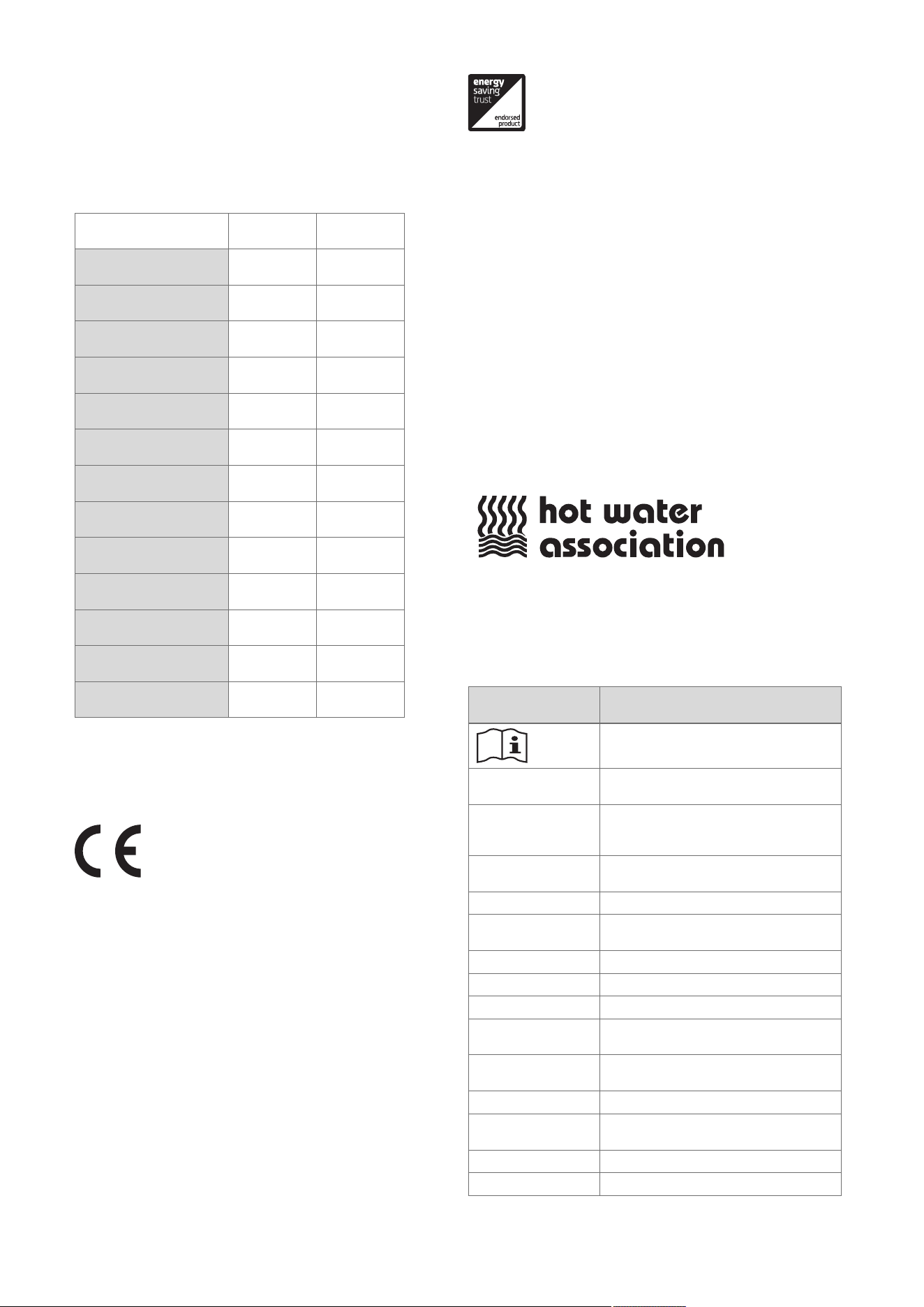
Information on the
data plate
Meaning
Read the instructions.
VU… Vaillant gas-fired wall-hung boiler for
heating
VUW…, VUI… Vaillant gas-fired wall-hung boiler for
heating and domestic hot water genera-
tion
..6/5-5 Gross calorific value power/product
generation equipment
ecoTEC plus Product designation
2H, G20 – 20 mbar
(2.0 kPa)
Gas group and gas connection pressure
as set at the factory
ww/yyyy Production date: Week/year
Cat. Approved gas boiler category
Types Approved unit types
PMS Permissible operating pressure, heating
mode
PMW Permissible operating pressure for do-
mestic hot water generation
T
max.
Max. flow temperature
ED 92/42 Current efficiency directive fulfilled with
4* rating
V Hz Mains voltage and mains frequency
W Max. electrical power consumption
16 Installation and maintenance instructions 0020244997_07
Information on the
data plate
Meaning
IP IP rating
Heating mode
Domestic hot water generation
P Nominal heat output range
Q Heat input range
D Nominal domestic hot water draw-off rate
Barcode with serial number,
7th to 16th digit = product article number
Note
Make absolutely sure that the product is compat-
ible with the gas group at the installation site.
5.5 Serial number
The serial number can be found on a plastic label behind the
front flap and on the identification plate.
Note
The serial number can also be shown on the
display of the product (→ Operating instructions).
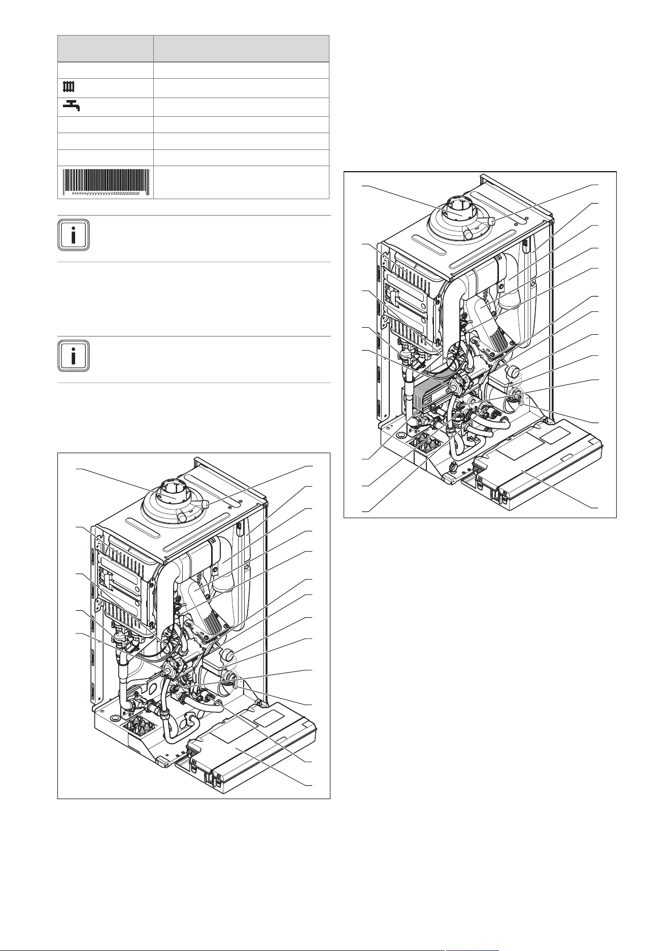
5.6 Product design
5.6.1 Functional elements, product for heating
mode only
7
8
9
10
13
11
12
14
15
18
5
4
1
2
3
16
17
6
1 Gas valve assembly
2 Water pressure sensor
3 Venturi with mass flow
sensor
4 Heat exchanger
5 Connection for the
air/flue pipe
6 Flue gas test point
7 Expansion vessel
8 Air intake pipe
9 Compact thermal
module
10 Ignition electrode
11 Fan
12 Automatic air vent
13 Manometer
14 Internal pump
15 Bypass valve
16 Expansion relief valve
17 Prioritising diverter
valve
18 Electronics box
5.6.2 Functional elements, product with domestic
hot water generation
7
8
9
10
13
11
12
14
18
19
17
5
4
1
2
3
20
15
16
6
1 Gas valve assembly
2 Water pressure sensor
3 Venturi with mass flow
sensor
4 Heat exchanger
5 Connection for the
air/flue pipe
6 Flue gas test point
7 Expansion vessel
8 Air intake pipe
9 Compact thermal
module
10 Ignition electrode
11 Fan
12 Automatic air vent
13 Manometer
14 Internal pump
15 Bypass valve
16 Expansion relief valve
17 Electronics box
18 Prioritising diverter
valve
19 Impeller sensor (do-
mestic hot water)
20 Secondary heat ex-
changer

0020244997_07 Installation and maintenance instructions 17
5.7 Safety Devices
5.7.1 Electrical Supply Failure
The boiler will not work without an electrical supply. Normal
operation of the boiler should resume when the electrical
supply is restored.
Reset any external controls, to resume normal operation of
the central heating.
If the boiler does not resume normal operation press the
reset button. If the boiler does not resume normal operation
after this call your Installation/Servicing company or Vaillant
service.
5.7.2 Overheating Safety
The boiler software is designed to recognise the potential for
an overheat lockout and will shutdown before this happens.
To restart the boiler, press the reset button on the boiler
interface.
If the boiler fails to resume normal operation and all external
controls are calling for heat, then call your Installation/ Servi-
cing company or Vaillant service.
5.7.3 Frost protection
The appliance has a built in frost protection device that pro-
tects the boiler from freezing. With the gas and electric sup-
plies ON and irrespective of any room thermostat setting, the
frost protection device will operate the pump when the tem-
perature of the boiler water falls below 12 °C.
A timer is used so that the temperature can be checked peri-
odically. After 10 minutes the pump will be stopped if the
temperature is higher than 10 °C or has already reached
35 °C. The burner will activate if the boiler temperature does
not reach 10 °C after 30 minutes or at any time if the temper-
ature drops to 5 °C.
The burner will switch off when the temperature reaches
35 °C.
5.7.4 Condensate Drain Blockage
As a safety feature the boiler will stop working if the con-
densate drain becomes blocked. During freezing conditions
this may be due to the forming of ice in the condense drain
external to the house. Release an ice blockage by the use
of warm cloths on the pipe. After pressing reset the boiler
should restart.
18 Installation and maintenance instructions 0020244997_07
6 Set-up
6.1 Checking the scope of delivery
▶ Check that the scope of delivery is complete and intact.
6.1.1 Scope of delivery
Validity: Product with heating mode only
Num-
ber
Designation
1
Heat generator
1 Installation set containing the following:
1
- Unit mounting bracket
1
- Expansion relief valve connection pipe
1
- Gas connection pipe
2 - Heating flow/return connection pipe
3 - Service valve
3
- Bag with small parts
1 Lower cover
1
Mounting template
1 Enclosed documentation
6.1.2 Scope of delivery
Validity: Product with integrated hot water generation
Num-
ber
Designation
1
Heat generator
1 Installation set containing the following:
1
- Unit mounting bracket
1
- Expansion relief valve connection pipe
1
- Gas connection pipe
2 - Heating flow/return connection pipe
2 - Cold water, domestic hot water connection pipe
4 - Service valve
3
- Bag with small parts
1
- Double Check Valve
1 Lower cover
1
Mounting template
1 Enclosed documentation
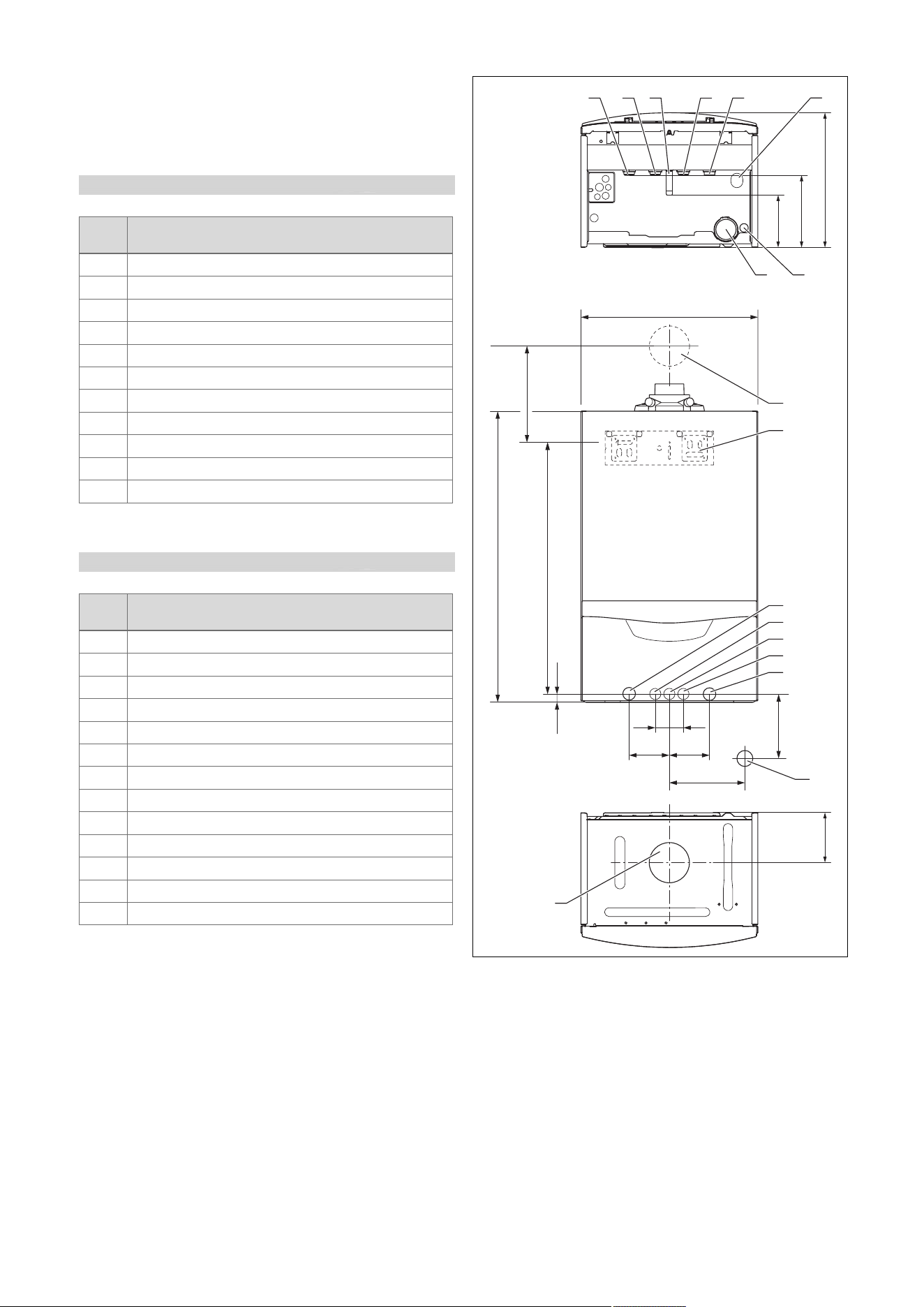
6.2 Dimensions
720
20
624
160
125
188
100 100
3535
440
A
B
180
125
2
1
3
5
7
9
8
4*
6*
6*
4*
7
11 10
3
5
12
1 Air/flue pipe wall duct
2 Unit mounting bracket
3 Heating flow (22 × 1.5
diameter)
4 Domestic hot water
connection (15 × 1.5
diameter)
5 Gas connection
(15 × 1.5 diameter)
6 Cold water connection
(15 × 1.5 diameter)
7 Heating return (22 × 1.5
diameter)
8 R1 tundish/condensate
trap connection
9 Air/flue pipe connection
10 Condensate discharge
connection, 19 mm
diameter
11 Condensate trap
12 Drain pipework connec-
tion, expansion relief
valve, heating, 15 mm
diameter
* Only products with
integrated domestic
hot water generation
** Only products with
heating mode only
0020244997_07 Installation and maintenance instructions 19
Consult the installation template that is supplied to find the
dimension A.
Installation depth, dimension B
VU 126/5-5 (H-GB) ecoTEC plus 612
338 mm
VU 156/5-5 (H-GB) ecoTEC plus 615
338 mm
VU 186/5-5 (H-GB) ecoTEC plus 618
338 mm
VU 186/5-5 (P-GB) ecoTEC plus 618
338 mm
VU 246/5-5 (H-GB) ecoTEC plus 624
338 mm
VU 306/5-5 (H-GB) ecoTEC plus 630
372 mm
VU 306/5-5 (P-GB) ecoTEC plus 630
372 mm
VU 386/5-5 (H-GB) ecoTEC plus 637
406 mm
VUW 196/5-5 (H-GB) ecoTEC plus 825
338 mm
VUW 246/5-5 (H-GB) ecoTEC plus 832
338 mm
VUW 246/5-5 (P-GB) ecoTEC plus 832
338 mm
VUW 306/5-5 (H-GB) ecoTEC plus 835
372 mm
VUW 286/5-5 (H-GB) ecoTEC plus 838
406 mm
6.3 Installation site
This boiler is not suitable for outdoor installation. This boiler
may be installed in any room. However if the boiler is being
installed in a room containing a bath or shower it must only
be installed in zones 2 or 3. In GB this is the current I.E.E.
WIRING REGULATIONS and BUILDING REGULATIONS. In
IE reference should be made to the current edition of I.S.813
“Domestic Gas Installations” and the current ETCI rules.
If the boiler is to be installed in a timber frame building it
should be fitted in accordance with the current version of the
Institute of Gas Engineers document IGE/UP/7. If in doubt
seek advice from local gas undertaking or the manufacturer.
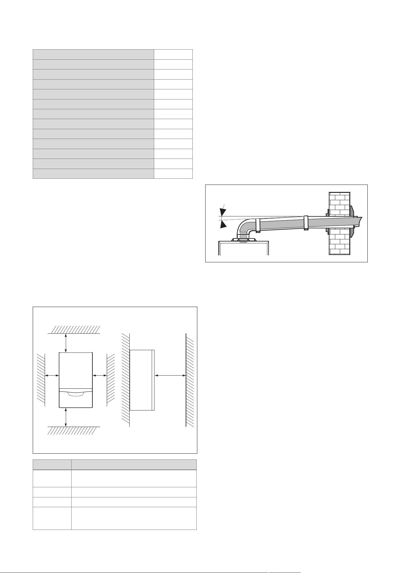
6.4 Minimum clearances
B A
C C D
Minimum clearance
A 165 mm: Air/flue pipe, 60/100 mm diameter
275 mm: Air/flue pipe, 80/125 mm diameter
B 180 mm; optimum approx. 250 mm
C 5 mm; optimum approx. 50 mm
D 500 mm in front of the heat generator to enable
easy access for maintenance work (may be
provided by an opening door).
It is not necessary to maintain a clearance between the
product and components made of combustible materials that
go beyond the minimum clearances.
6.5 Compartment Ventilation
The boilers are very high efficiency appliances.
As a consequence the heat loss from the appliance casing
during operation is very low.
Compartment ventilation is not required as the products are
only certified, and can only be fitted with a concentric flue
system.
6.6 Air/flue pipe
6.6.1 Regulation
Different flue outlet configurations can be carried out.
– Consult the installation manual for air/flue gas systems
for more information about the other possibilities and
associated accessories.
Minimum fall
44 mm/m
– Standard flue terminal kits have an in-built fall back to
the boiler to drain the condensate. These can be fitted
level between the appliance and the termination position.
All other extended flues must have a fall of at least 44
mm/m.
The maximum length of the flue outlet is defined according to
its type (for example C13).
– Whatever the kind of flue system chosen, observe the
minimum distances to position the flue terminals.
– To install the flue, refer to the separate flue instruction
supplied with your appliance.
– Explain these requirements to the user of the appliance.
In GB the minimum acceptable siting dimensions for the
terminal from obstructions, other terminals and ventilation
openings are shown in diagram overleaf.
In IE the minimum distances for flue terminal positioning
must be those detailed in I.S. 813 “Domestic Gas Installa-
tions”.
The terminal must be exposed to the external air, allowing
free passage of air across it at all times.
Being a condensing boiler some pluming may occur from
the flue outlet. This should be taken into consideration when
selecting the position for the terminal.
20 Installation and maintenance instructions 0020244997_07
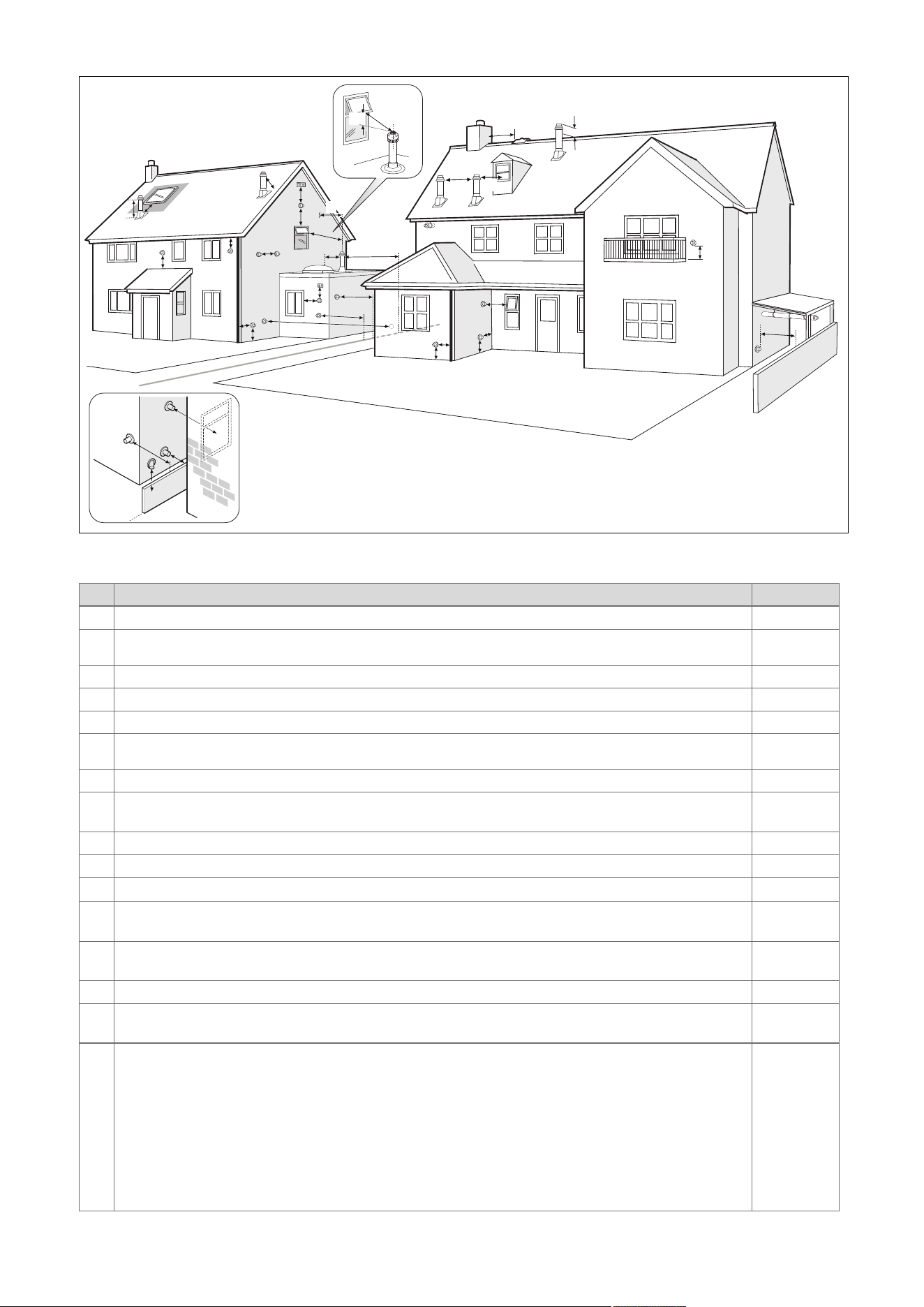
6.6.2 Position of the air/flue terminal
J
J
N
Q
S
S
P
U
B
Boundary
G
D
J
J
R
V
M
T
G
C
W
E
F
L
A
K
S
P
S
F
X
A
Y
Boundary
Z
H
Aa
S
Z
Ba
6.6.2.1 Positioning the terminal of a fan-supported flue system
Installation site Dimensions
A
Adjacent to a boundary. 300 mm
B
1)
The dimension below eaves, balconies and car ports can be reduced to this value, as long as the flue terminal is
extended to clear any overhang. External flue joints must be sealed with a suitable silicon sealant.
25 mm
C Between a vertical flue terminal and a window or dormer window on a roof. 1,500 mm
D Between terminals facing each other. 1,200 mm
E Vertical flue clearance, adjacent to a boundary line. 300 mm
F
2)
Distance to a boundary line, unless it will cause a nuisance. BS 5440:Part 1 recommends that care is taken
when siting terminal in relation to boundary lines.
600 mm
G Minimum clearance from a skylight to a vertical flue or to another vertical flue. Min. 300 mm
H
Vertical flue clearance, to noncombustible building material.
Vertical flue clearance to combustible building material.
500 mm
1,500 mm
J Above, below and either side of an opening door, air vent or opening window. 300 mm
K Diagonally to an opening door, air vent or opening window. 600 mm
L
2)
To an internal or external corner. 200 mm
M
Below a Velux window.
Above or to either side of the Velux window.
2,000 mm
600 mm
N
From a pitched roof.
In regions with heavy snowfall.
400 mm
500 mm
P From vertical drain pipes and soil pipes. 25 mm
Q
Below eaves.
Below gutters, pipe and drains.
200 mm
75 mm
1) There should be no ventilation/opening in the eaves within 300 mm distance of the terminal.
2) These dimensions comply with the building regulations, but they may need to be increased to avoid wall
staining and nuisance from pluming depending on site conditions.
– Terminals must be positioned so to avoid combustion products entering the building.
– Support the flue at approximately one metre intervals and at a change of direction, use suitable brackets and
fixings.
– Installations in car ports are not recommended.
– The flue cannot be lower than 1 metre from the top of a lightwell due to the build up of combustion products.
– Dimensions from a flue terminal to a fanned air inlet to be determined by the ventilation equipment.
0020244997_07 Installation and maintenance instructions 21
Installation site Dimensions
R
The dimension below eaves, balconies and car ports can be reduced to this value, as long as the flue terminal is
extended to clear any overhang. External flue joints must be sealed with suitable silicon sealant.
25 mm
S Above adjacent ground or balcony. 300 mm
T
2)
Distance to a surface facing a terminal, unless it will cause a nuisance. BS 5440: Part 1 recommends that care
is taken when siting terminals in relation to surfaces facing a terminal.
600 mm
U Clearance alongside another terminal. 300 mm
V Above roof level. 300 mm
W Minimum to vertical structure on roof, roof vent. Min. 300 mm
X Minimum to opening in adjacent building. Min.
2000 mm
Y Minimum at an angle to a boundary which is not less than 300 mm to the terminal Min. 600 mm
Z Minimum measured to the nearest corner of the OPEN window Min. 600 mm
Aa No more than this value above ridge. Max.
300 mm
Ba Not less than this value below the opening window Min. 300 mm
1) There should be no ventilation/opening in the eaves within 300 mm distance of the terminal.
2) These dimensions comply with the building regulations, but they may need to be increased to avoid wall
staining and nuisance from pluming depending on site conditions.
– Terminals must be positioned so to avoid combustion products entering the building.
– Support the flue at approximately one metre intervals and at a change of direction, use suitable brackets and
fixings.
– Installations in car ports are not recommended.
– The flue cannot be lower than 1 metre from the top of a lightwell due to the build up of combustion products.
– Dimensions from a flue terminal to a fanned air inlet to be determined by the ventilation equipment.
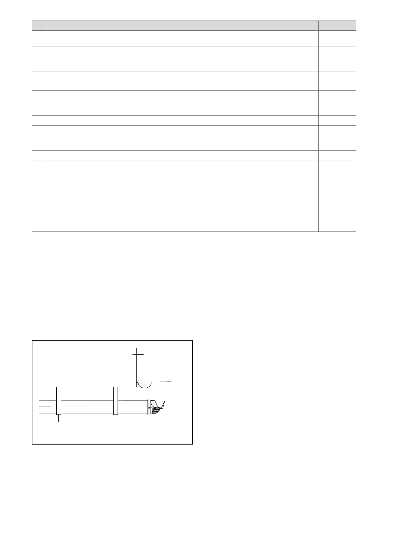
6.6.2.2 Horizontal terminal positioning
BS 5440-1 recommends that fanned flue chimney terminals should be positioned as follows:
a) at least 2 m from an opening in the building directly opposite, and
b) so that the products of combustion are not directed to discharge directly across a boundary if the products are likely to
cause a nuisance to a neighbour or discharge over a walkway or patio.
For IE see current issue of IS 813.
For boilers covered within this manual.
Dimensions B and R:
These clearances may be reduced to 25 mm without affecting the performance of the boiler. In order to ensure that the con-
densate plume does not affect adjacent surfaces the terminal should be extended as shown below.
Balcony/eaves
Gutter
Adequately secured
air/flue gas pipe
The flue pipe must
protrude beyond any overhang
You can use a plume management kit to enable the termination point to be positioned and directed away from the building
fabric.
22 Installation and maintenance instructions 0020244997_07
6.6.3 Flue Configuration Description
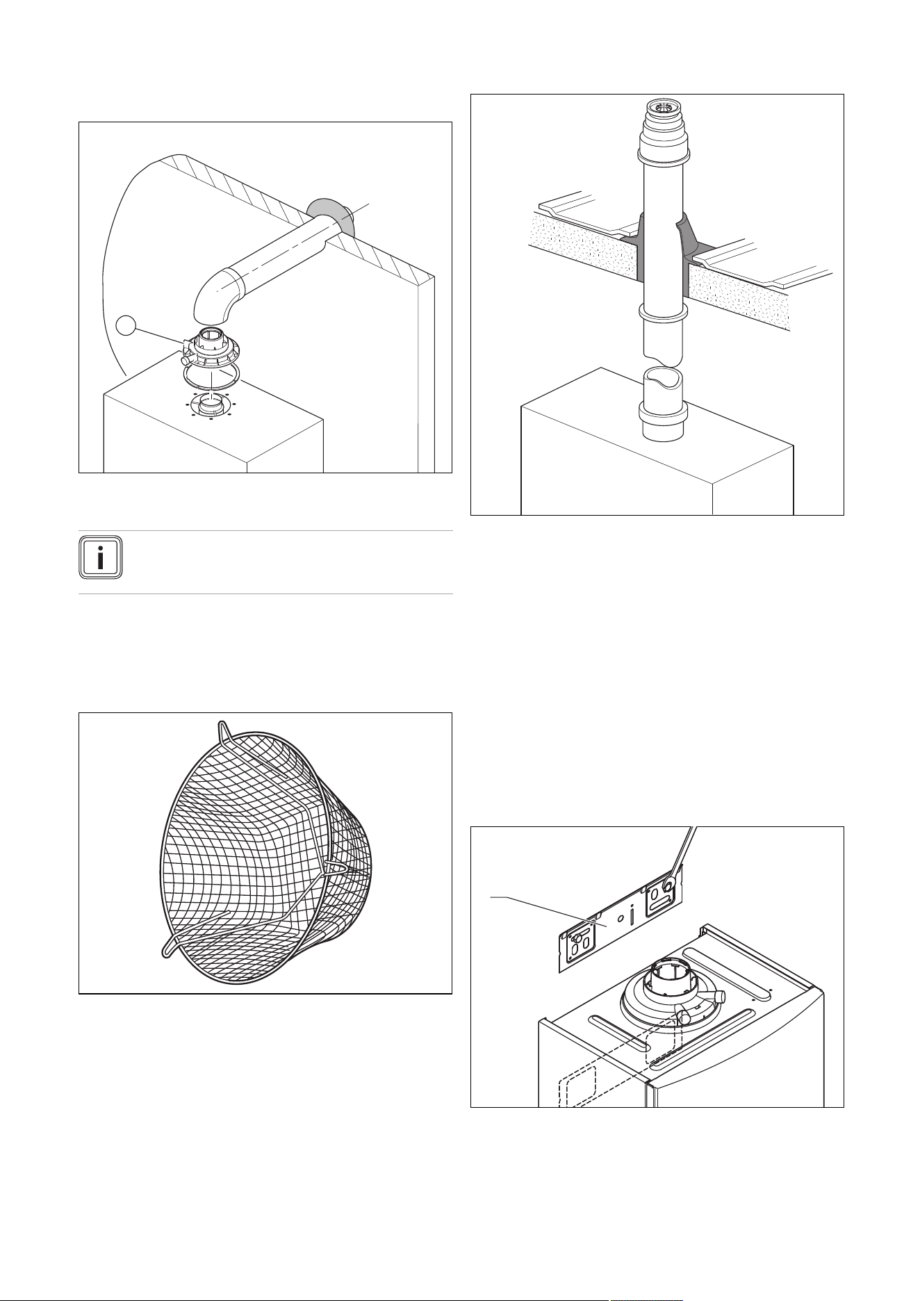
6.6.3.1 Horizontal Concentric Flue ⌀ 60/100 mm or
⌀ 80/125 mm (C13 type installation)
1
1 Gasket (fitted)
Note
If the terminal is at less than 1.80 m from the
ground, you must install a terminal protection kit.
Consult the separate installation manual for air/flue gas sys-
tems supplied with your appliance for all possibilities and as-
sociated accessories and how to install the flue system.
6.6.3.2 Terminal protection
A terminal guard is required if persons could come into con-
tact with the terminal or the terminal could be subject to dam-
age.
If a terminal guard is required, it must be positioned to
provide minimum of 50 mm clearance from any part of the
terminal and be central over the terminal.
The guard should be similar to that shown in the figure.
6.6.3.3 Vertical Concentric Flue ⌀ 60/100 mm or
⌀ 80/125 mm (C33 type installation)
Consult the separate installation manual for air/flue gas sys-
tems supplied with your appliance for all possibilities and as-
sociated accessories and how to install the flue system.
6.7 Using the installation template
▶ Use the installation template to ascertain the locations at
which you need to drill holes and make breakthroughs.
6.8 Wall-mounting the product
1. Check the load-bearing capacity of the wall.
2. Note the total weight of the product.
3. Only use fixing material that is permitted for the wall.
4. If required, ensure that mounting apparatus on-site has
sufficient load-bearing capacity.
5. Wall-mount the product as described.
1
6. Install the product bracket (1) on the wall.
7. Hang the product on the product bracket from above
using the hanging bracket.
0020244997_07 Installation and maintenance instructions 23
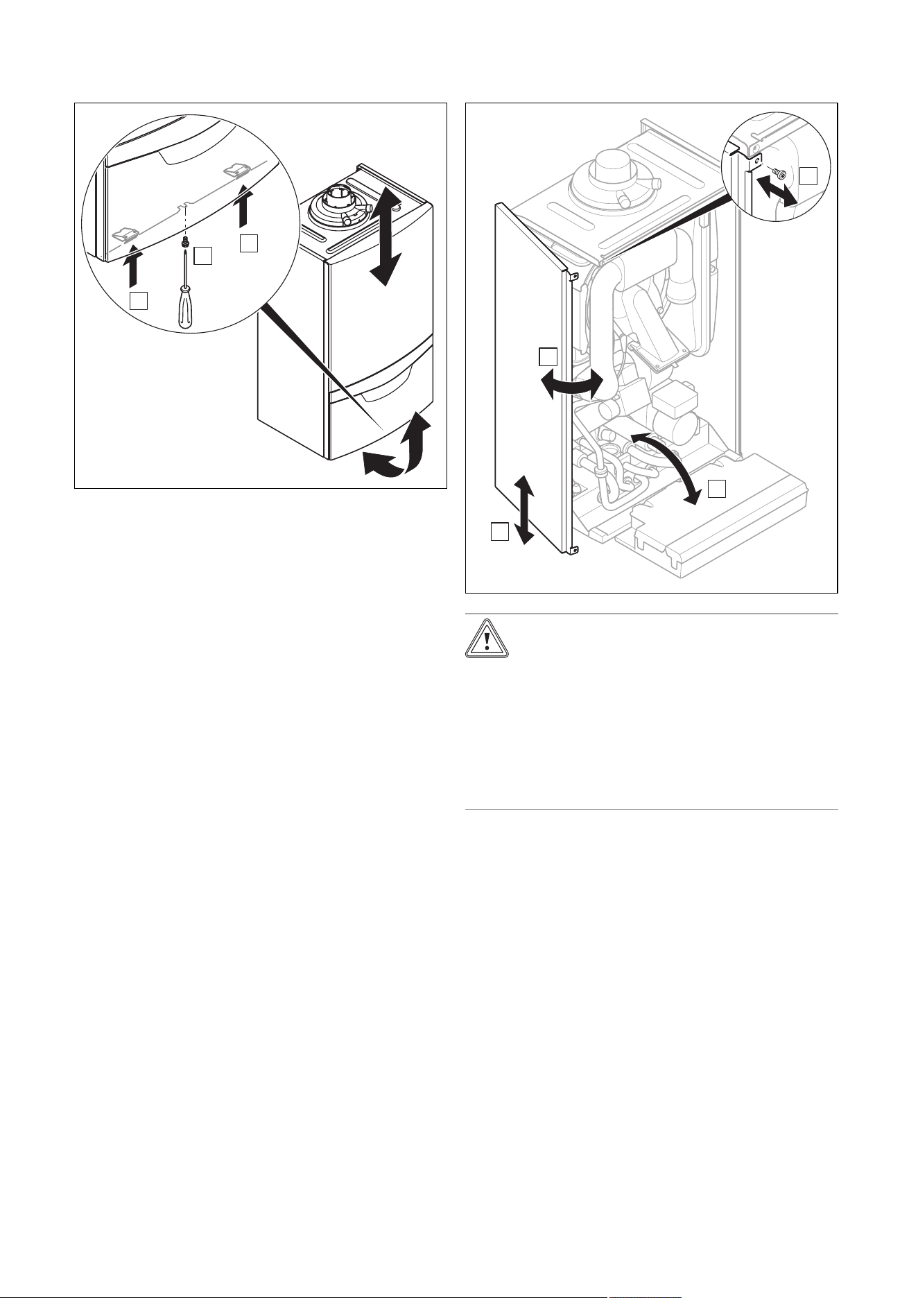
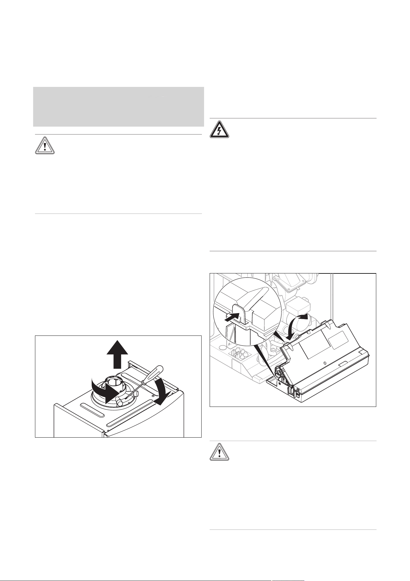
6.9 Removing/installing the front casing
6.9.1 Removing the front casing
B
A
B
▶ Remove the front casing as shown in the illustration.
6.9.2 Installing the front casing
▶ Refit the components in the reverse order.
6.10 Removing/installing the side section
6.10.1 Removing the side section
2x
B
A
C
D
Caution.
Risk of material damage caused by mech-
anical deformation.
Removing both side sections may cause
mechanical distortion in the product, which
may cause damage to the piping, for ex-
ample, and potentially result in leaks.
▶ Always only remove one side section –
never both side sections at the same time.
▶ Remove the side section as shown in the illustration.
6.10.2 Installing the side section
▶ Refit the components in the reverse order.
24 Installation and maintenance instructions 0020244997_07
7 Installation
7.1 Installation requirements
7.1.1 Information on the gas group
In the as-supplied condition, the product is preset for opera-
tion with the gas group indicated on the data plate.
7.1.2 Purging the liquid gas tank
If the liquid gas tank is not purged properly, this may result in
ignition problems.
▶ Ensure that the liquid gas tank has been purged properly
before installing the product.
▶ If required, contact the filler or the liquid gas supplier.
7.1.3 Using the correct gas type
Using the incorrect gas type may cause fault shutdowns in
the product. Ignition and combustion noise may occur in the
product.
▶ Only use the gas type listed on the data plate.
7.2 Preparing for installation
1. Make sure that the existing gas meter is capable of
passing the rate of gas supply required.
2. Consider the maximum heat output given in DHW
mode.
3. Install a system separator (to be provided on-site) dir-
ectly on the cold water connection for the combi boiler.
4. Install the following components:
– Draining cocks at the lowest points in the heating
installation (→ current version of "BS 2879")
– A stopcock on the cold water connection
– A stopcock in the gas pipe
5. Check that the volumetric capacity of the expansion
vessel is sufficient for the system volume.
Condition: The volume of the installed expansion vessel is insufficient
▶ Install an additional expansion vessel, connected as
close to the product as possible, in the heating return.
Condition: External expansion vessel installed and warm start active
▶ Install a non-return valve in the product outlet (heating
flow) or decommission the internal expansion vessel in
order to prevent the warm start function from being in-
creasingly activated due to backflow.
6. Install the connection pipes such that they are free
from mechanical stress.
7. If you use non-diffusion-tight plastic pipes in the heat-
ing installation, ensure that no air gets into the heat
generator circuit.
8. Only solder connectors if the connectors are not yet
screwed to the service valves.
9. Only bend connection pipes if they have not yet been
connected to the product.
10. Flush the heating installation thoroughly before in-
stalling the product.
11. If, during gas leak-tightness tests, you also place the
gas pipes and the gas valve assembly in the product
under pressure, use a max. test pressure of ≤ 11 kPa
(110 mbar).
12. If you cannot limit the test pressure to 11 kPa
(110 mbar), close any gas stopcocks that are installed
upstream of the product before you carry out the gas
leak-tightness test.
13. If, during gas leak-tightness tests, you have closed the
gas stopcock that is installed upstream of the product,
relieve the gas line pressure before you open this gas
stopcock.
14. Install a tundish with condensate siphon for the con-
densate discharge and the exhaust pipe on the expan-
sion relief valve. Route drain pipework that is as short
as possible, at a downward gradient away from the tun-
dish.
15. Insulate bare pipes exposed to environmental influ-
ences to protect them from frost using suitable insula-
tion material.
7.3 Descaling the water
Scale deposition increases as the water temperature in-
creases.
▶ Descale the water as required.
7.4 Installing the gas connection
1. Install the gas pipe in accordance with the recognised
rules of technology.
2. In doing so, ensure that the dimensioning of the gas
pipes is sufficient since, otherwise, this may lead to
fault shutdowns of the unit.
3. Connect the product to the gas pipe as shown in ac-
cordance with the recognised rules of good engineer-
ing practice.
4. Remove the residues from the gas pipe by blowing
through the gas pipe beforehand.
5. Purge the gas pipe before start-up.
0020244997_07 Installation and maintenance instructions 25
7.5 Checking the gas line for leak-tightness
▶ Check the entire gas line properly for leak-tightness.
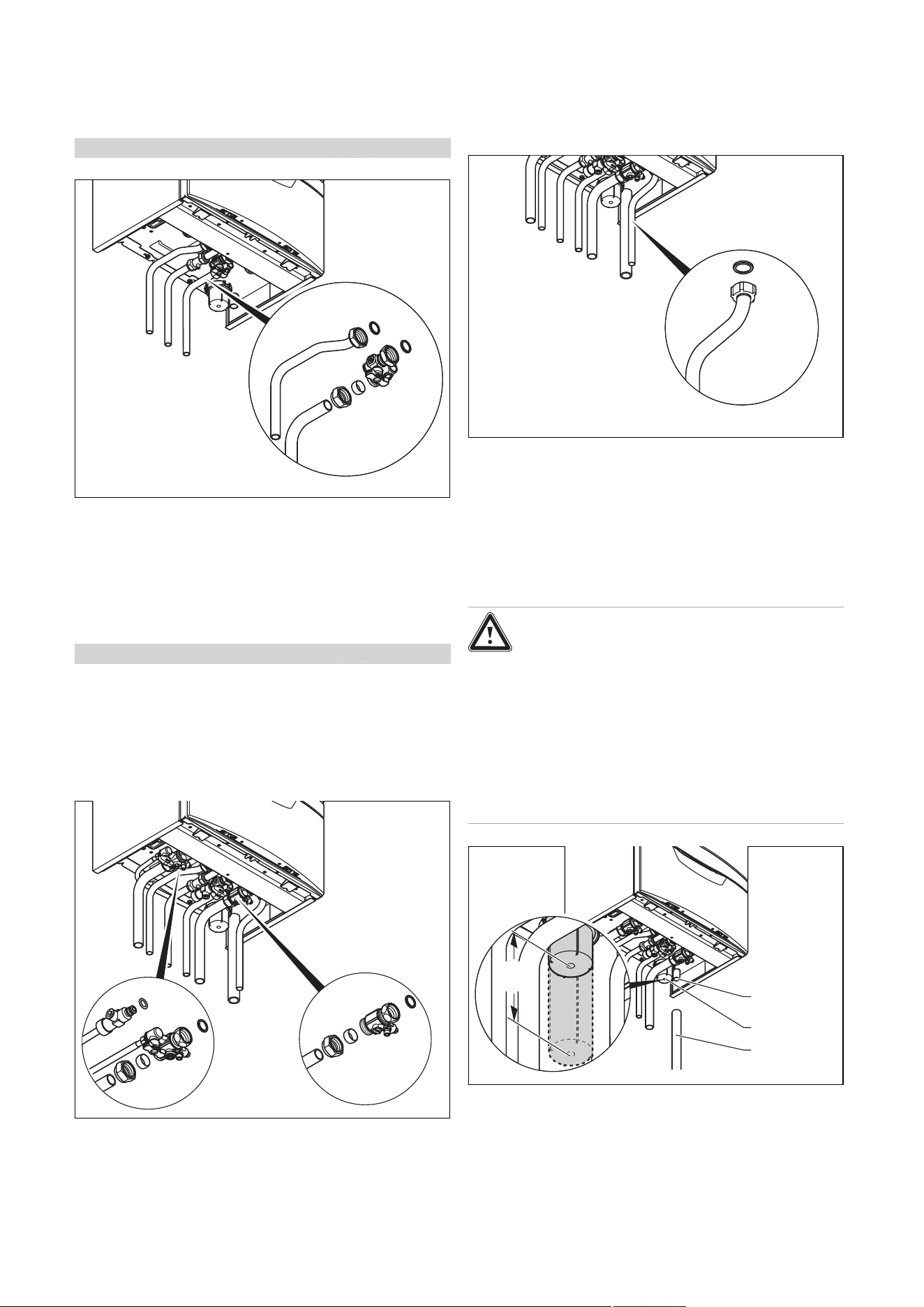
7.6 Installing the hot and cold water connection
Validity: Product with integrated hot water generation
1. Make the water connections as shown in accordance
with the relevant standards.
2. Ensure correct water pressure and flow requirements
and that any expansion can be accommodated with the
cold supply pipe work.
7.7 Connecting the domestic hot water cylinder
Validity: Product with heating mode only
▶ When connecting the domestic hot water cylinder, follow
the Installation instructions for the domestic hot water
cylinder.
7.8 Connecting the heating flow and heating
return
▶ Make the heating connections as shown in accordance
with the relevant standards.
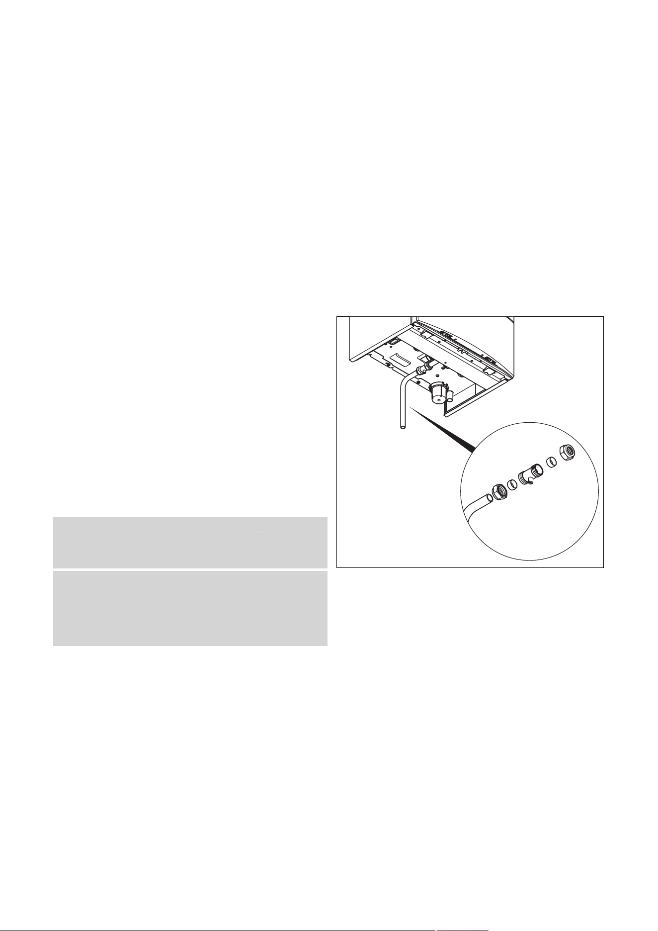
7.9 Installing the drain pipe on the expansion
relief valve
1. Install the drain pipe for the expansion relief valve so
that it does not interfere with the removal and fitting of
the lower section of the condensate trap.
2. Install the drain pipe as shown (do not shorten).
3. Make sure that the end of the pipe is visible.
4. Ensure that discharged water or steam cannot cause
injury to persons or damage to electronic components.
5. Ensure the discharge pipe work is installed, routed and
terminated correctly to minimise the risk of freezing up.
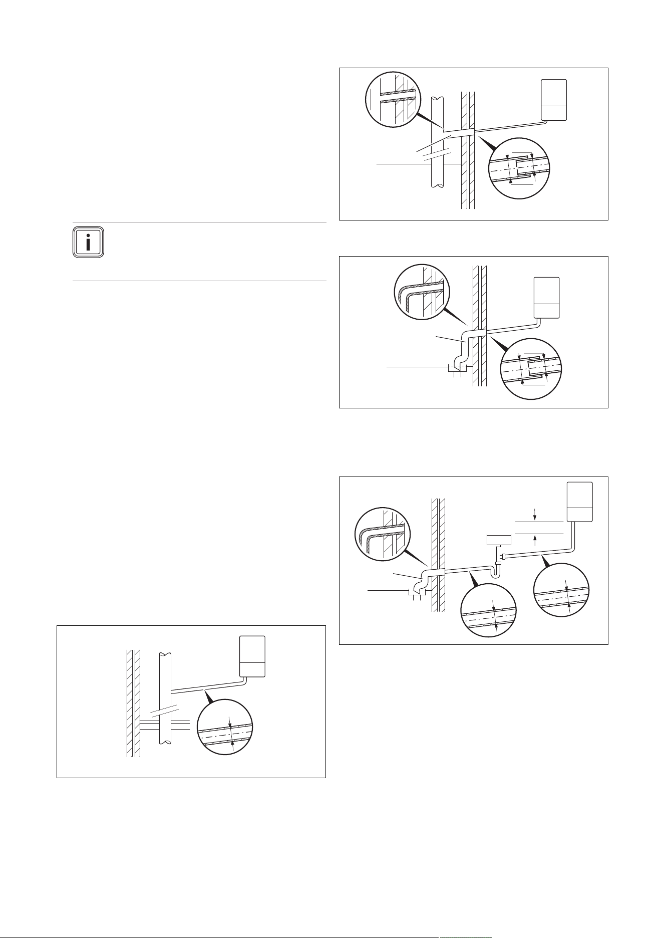
7.10 Connecting the condensate discharge pipe
Danger!
Risk of death from escaping flue gases!
The condensate drain pipework for the si-
phon must not be connected tightly to waste-
water piping because, otherwise, the internal
condensate trap may be drained fully and flue
gas may escape.
▶ Do not connect the condensate drain
pipework tightly to the waste-water pip-
ing.
min.
180
11
2
3
The product is equipped with a condensate trap (2). The
condensate trap collects the condensate that has formed in
a vessel with a volumetric capacity of approximately 200 ml,
and intermittently releases the contents into the drain pipe.
This minimises the risk of the drain pipe freezing.
▶
Follow the instructions listed here and observe directives
and local regulations on condensate discharge.
26 Installation and maintenance instructions 0020244997_07
▶ If you cannot guarantee that the materials from which the
condensate discharge pipe is made are suitable, install a
system to neutralise the condensate.
▶ Connect the condensate discharge (1) to a condensate
discharge pipe (3) that has a minimum internal diameter
of 19 mm (30 mm internal diameter for all external pipes
that are fed out of the building) and is made from an acid-
resistant material (e.g. plastic overflow pipe).
– The condensate discharge pipework must have
a continuous fall (45 mm per metre) and should
whenever possible terminate at a suitable discharge
point within the heated envelope of the building
that will remain frost free under long periods of low
external temperatures.
Note
Ensure that the connection between the con-
densate discharge pipe and the drain hose is
not air-tight.
▶ During installation remove all burs from inside of cut pipe
work and avoid excessive adhesive which may trap small
pockets of water close to the pipe wall which can freeze
and build into a larger ice plug.
▶ As with other pipe work insulate the condensate dis-
charge pipe to minimise any risk of freezing and beware
when crossing cavities that the fall is maintained and the
pipe sleeved.
▶ Ensure that the condensate discharge pipe terminates in
a suitable location. Further information can be obtained
from BS 6798 Specification for installation of gas–fired
boilers of rated input not exceeding 70 kW net.
▶ Leave an installation space of at least 180 mm beneath
the condensate trap.
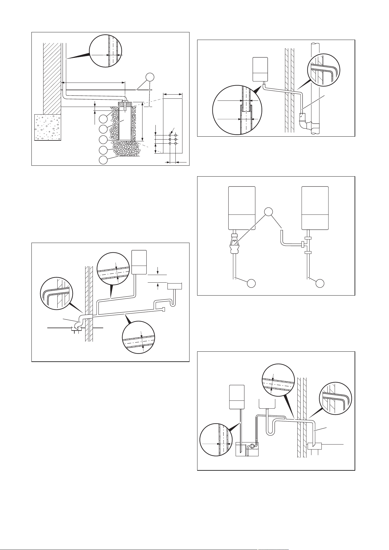
7.10.1 Condensate discharge systems
The condensate is discharged periodically in ‘slugs’ by si-
phonic action. It is not necessary to provide extra traps in the
discharge pipe as there is already a trap inside the boiler.
Fitting an extra trap may cause the boiler siphon to work in-
correctly. Refer to BS5546 or BS6798 for further advice on
disposal of boiler condensate.
7.10.1.1 Direct Connection to internal soil and vent
stack
Ø22mm
Preferred option
7.10.1.2 Direct connection to external soil and vent
stack
Ø22mm
Ø 32mm
≤ 3 m
7.10.1.3 External termination to gulley or hopper
Ø22mm
Ø 32mm
≤ 3 m
Best practice
7.10.1.4 Internal termination into combined sink
waste
Ø32mm
Ø22mm
≥ 3 m
100mm
Preferred option for external termination
0020244997_07 Installation and maintenance instructions 27
7.10.1.5 External termination into soakaway
< 500 mm
100 mm
< 300 mm
50 25 25
< 25
25
Ø12
Ø32mm
≤ 3 m
1
2
3
4
5
6
1 Ground (either/or)
2 Seal
3 Plastic tube,
100 mm diameter
4 Bottom of sealed tube
5 Limestone chippings
6 Hole depth 400 mm
minimum
Least preferred option, must not terminate in rain water drain
7.10.1.6 Internal termination downstream of sink
waste
100mm
Ø32mm
Ø22mm
≤ 3 m
Open end of pipe direct into gulley below ground level but
above water level
Susceptible to siphonage, must terminate in a gulley
7.10.1.7 External termination into rain water down
pipe
≤ 3 m
Ø22mm
Ø 32mm
NB only combined foul/rainwater drain
7.10.1.8 Additional methods of introducing air
breaks
1
2 3
1 Air break
2 Using a tundish
3 Using a pipe
7.10.1.9 Connection of condensate pump
Ø32mm
Ø22mm
≥ 3 m
Preferred option for external connection
28 Installation and maintenance instructions 0020244997_07
7.11 Flue installation
7.11.1 Installing and connecting the air/flue pipe
1. You can find out which air/flue pipes may be used
by consulting the enclosed set-up instructions for the
air/flue system.
2. Observe the information on positioning the air/flue ter-
minal.
Condition: Installation in damp rooms
▶ You must connect the product to a room-sealed air/flue
system. The combustion air must not be taken from the
installation site.
Caution.
Risk of poisoning due to escaping flue
gas.
Mineral-oil-based greases can damage the
seals.
▶ Instead of grease, use only water or com-
mercially available soft soap to aid install-
ation.
3. Install the air/flue pipe using the set-up instructions.
7.11.2 Replacing the connector for the air/flue pipe
as required
1. Replace the connector for the air/flue pipe as required.
The product-specific standard equipment is listed un-
der Technical data.
2. Remove the connector for the air/flue pipe.
(→ Page 28)
3. If required, install the connector for the air/flue pipe,
80/125 mm diameter. (→ Page 28)
7.11.2.1 Removing the connector for the air/flue pipe
1.
2.
3.
1. Insert a screwdriver into the slot between the test
points.
2. Press the screwdriver carefully down (1.).
3. Turn the connector anti-clockwise (2.) as far as it will
go and then remove it by pulling it upwards (3.).
7.11.2.2 Installing the connector for the air/flue pipe,
80/125 mm diameter
1. Remove the connector for the air/flue pipe.
2. Insert the alternative connector. In doing so, pay atten-
tion to the latching lugs.
3. Turn the connector clockwise until it clicks into position.
7.12 Electrical installation
Only qualified electricians may carry out the electrical install-
ation.
Danger!
Risk of death from electric shock!
Power supply terminals L and N remain live
even if the on/off button is switched off:
▶ Disconnect the product from the power
supply by switching off all power supplies
at all poles (electrical partition with a con-
tact gap of at least 3 mm, e.g. fuse or cir-
cuit breaker).
▶ Secure against being switched back on
again.
▶ Wait for at least 3 minutes until the capa-
citors have discharged.
▶ Check that there is no voltage.
7.12.1 Opening the electronics box
▶ Open the electronics box as shown in the figure.
7.12.2 Carrying out the wiring
Caution.
Risk of material damage caused by incor-
rect installation.
Mains voltage at incorrect terminals and plug
terminals may destroy the electronics.
▶ Do not connect any mains voltage to the
eBUS terminals (+/-).
▶ Only connect the mains connection cable
to the terminals marked for the purpose.
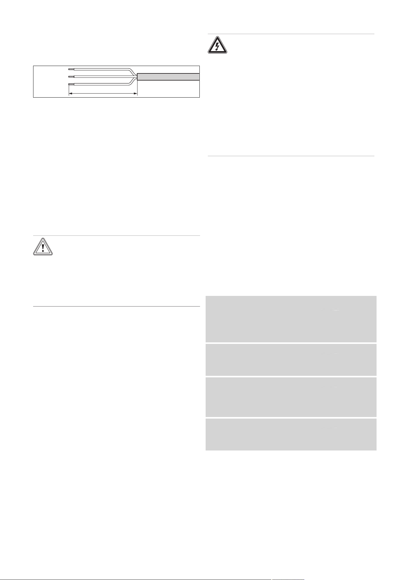
0020244997_07 Installation and maintenance instructions 29
1. Route the connection cables of the components to
be connected through the grommet provided on the
underside of the product on the left.
2. Use strain reliefs.
3. If required, shorten the connection cables.
30 mm
≤
4. Strip the flexible ducts as shown in the figure. In doing
so, ensure that the insulation on the individual conduct-
ors is not damaged.
5. Only strip inner conductors just enough to establish
good, sound connections.
6. To avoid short circuits resulting from loose individual
wires, fit conductor end sleeves on the stripped ends of
the conductors.
7. Screw the relevant plug to the connection cable.
8. Check whether all conductors are inserted mechanic-
ally securely in the plug terminals. Remedy this if ne-
cessary.
9. Plug the plug into the associated PCB slot; see the
wiring diagram in the appendix.
7.12.3 Establishing the power supply
Caution.
Risk of material damage due to high con-
nected voltage.
At mains voltages greater than 253 V, elec-
tronic components may be damaged.
▶ Make sure that the rated voltage of the
mains is 230 V.
1. Observe all valid regulations.
2. Make sure that the nominal mains voltage is 230 V.
3. Provide one common power supply for the boiler and
for the corresponding control:
– Power supply: Single-phase, 230 V, 50 Hz
– Fuse protection: ≤ 3 A
4. Do not interrupt the mains supply with a time switch or
programmer.
5. Open the electronics box. (→ Page 28)
6. Connect the product using a fixed connection and an
electrical partition with a contact gap of at least 3 mm
(e.g. fuses or power switches).
7. Isolation should preferably be by a double pole
switched fused spur box having a minimum contact
separation of 3 mm on each pole. The fused spur box
should be readily accessible and preferably adjacent to
the boiler. It should be identified as to its use.
8. Route a three-core power supply cable that complies
with the relevant standards through the grommet and
into the product.
– Power supply cable: Flexible duct
9. Carry out the wiring. (→ Page 28)
10. Remove the supplied plug from the retainer in the elec-
tronics box and screw the plug onto the power supply
cable.
11. Close the electronics box.
12. Make sure that access to the power supply is always
available and is not covered or blocked.
7.12.4 Installing the product in a wet room
Danger!
Risk of death from electric shock!
If you install the product in a room with high
levels of moisture, e.g. a bathroom, observe
the nationally recognised technical standards
for electrical installations.
▶ Connect the product using a fixed con-
nection and an electrical partition with a
contact gap of at least 3 mm (e.g. fuses or
power switches).
▶ Use a flexible line for the power supply
cable, which is routed through the grom-
met into the product.
1. Open the electronics box. (
→ Page 28)
2. Detach the plug from the PCB slot for the power supply
(X1).
3. Use a suitable, three-core power supply cable that
complies with the relevant standards.
4. Carry out the wiring. (→ Page 28)
5. Close the electronics box.
6. Observe the flue-gas connection that is required on a
room-sealed air/flue system. (→ Page 28)
7.12.5 Connecting controls to the electronics
1. Install the control if necessary.
2. Open the electronics box. (→ Page 28)
3. Carry out the wiring. (→ Page 28)
4. Observe the wiring diagram in the appendix.
Condition: Connecting a weather-compensated control or a room temperat-
ure control via eBUS
▶ Connect the control to the eBUS connection.
▶
Bridge the 24 V = RT connection (X100 or X106), if there
is not already a bridge.
Condition: Connecting a low-voltage control (24 V)
▶ Remove the bridge and connect the control to the
24 V = RT connection (X100 or X106).
Condition: Connecting 230 volt controller
▶ Connect the switched live supply of your 230 V RT to the
RT marked X1 position (besides LNPE). Do NOT connect
the 230 V to any other terminal e.g. not to X100.
Condition: Connecting a limit thermostat for underfloor heating
▶ Remove the bridge and connect the limit thermostat to
the Burner off connection.
5. Close the electronics box.
6. For multi-circuit controls, change D.018 from Eco (in-
termittently operating pump) to Comfort (continuously
operating pump). (→ Page 39)
7.12.6 Connecting additional components
You can actuate an additional component with the aid of the
auxiliary relay that is installed, and you can actuate two other
components with the multi-functional module.

30 Installation and maintenance instructions 0020244997_07
7.12.6.1 Using the auxiliary relay
1. Connect an additional component directly to the integ-
rated auxiliary relay using the grey plug on the PCB.
2. Carry out the wiring.
3. To start up the connected component, select the com-
ponent in diagnostics code D.026. (→ Page 39)
7.12.6.2 Using the VR 40 ("2 in 7" multi-functional
module)
1. Install the components in accordance with the respect-
ive instructions.
Condition: Components connected to relay 1
▶ Activate D.027. (→ Page 39)
Condition: Components connected to relay 2
▶ Activate D.028. (→ Page 39)
7.12.7 Actuating the circulation pump according to
requirements
1. Carry out the wiring.
2. Connect the connection cable for the external button
using terminals 1 (0) and 6 (FB) on the X41 edge
connector, which is supplied with the control.
3. Plug the edge connector into the PCB slot X41.

0020244997_07 Installation and maintenance instructions 31
8 Operation
8.1 Operating concept
The operating concept and the read-off and setting facilities
of the operator level are described in the operating instruc-
tions.
An overview of the reading and setting options for the in-
staller level is included in the table in the appendix.
Installer level – Overview (→ Page 52)
8.2 Calling up the installer level
1. Only call up the installer level if you are a competent
person.
2. Navigate to Menu → Installer level and confirm by
pressing .
3. Set the value 17 (code) and confirm by pressing .
8.3 Live Monitor (status codes)
Menu → Live monitor
Status codes in the display provide information on the pro-
duct's current operating mode.
Status codes – Overview (→ Page 59)
8.4 Setting the hot water temperature
Validity: Product with integrated hot water generation OR Product with hot
water generation through external domestic hot water cylinder
Danger!
Risk of death from legionella.
Legionella multiply at temperatures below
60 °C.
▶ Ensure that the end user is familiar with
all of the Anti-legionella measures in order
to comply with the applicable regulations
regarding legionella prevention.
▶ Set the hot water temperature.
Condition: Water hardness: > 3.57 mol/m³
– Water temperature: ≤ 50 ℃

32 Installation and maintenance instructions 0020244997_07
9 Start-up
9.1 Carrying out the initial start-up
Initial start-up must be carried out by a customer service
technician or an authorised competent person using the
Benchmark Checklist. The Benchmark Checklist in the ap-
pendix (→ Page 72) of the installation instructions must be
filled in and stored carefully along with the unit's documenta-
tion.
▶ Carry out the start-up procedure using the Benchmark
Checklist in the appendix.
▶ Fill out and sign the Benchmark Checklist.
9.2 Switching the product on and off
▶ Press the product's on/off button.
◁ The display shows the basic display.
9.3 Running the installation assistants
The installation assistant is displayed whenever the product
is switched on until it has been successfully completed.
It provides direct access to the most important check
programmes and configuration settings for starting up the
product.
To recheck and reset the most important system parameters,
call up the Appliance config..
Menu → Installer level → Appliance config.
The settings options for more complex systems can be found
in the Diagnostics menu.
Menu → Installer level → Diagnostics menu
▶ Press to confirm installation assistant start-up.
◁ All heating and hot water requests are blocked whilst
the installation assistant is active.
Note
If you do not confirm the launch of the install-
ation assistant within 10 seconds of switching
the system on, the basic display reappears.
▶ To access the next point, confirm by pressing in each
case.
9.3.1 Language
▶ Set the required language.
▶ To confirm the set language and to avoid unintentionally
changing it, press to confirm this twice.
If you have unintentionally set a language that you do not
understand, proceed as follows to change it:
▶ Press and hold and at the same time.
▶ Also briefly press .
▶ Press and hold and until the display shows the
language setting option.
▶ Select the required language.
▶ Press twice to confirm this change.
9.3.2 Filling mode
Filling mode (check programme P.06) is activated automatic-
ally in the installation assistant for as long as the filling mode
appears on the display.
9.3.3 Purging
1. Unlike in the Check programs menu, to purge the
system, start check programme P.00 by pressing
or .
2. If you need to change the circuit that is being purged,
press .
9.3.4 Target feed temperature, hot water
temperature, Comfort mode
1. To set the target flow temperature, hot water temperat-
ure and Comfort mode, use and .
2. Press to confirm this setting.
9.3.5 Heating partial load
The heating partial load of the product is set to Auto at the
factory. The product independently determines the optimum
heating output depending on the current heat demand of
the system. You can retroactively change the setting in the
Diagnostics menu under D.000.
9.3.6 Auxiliary relay and multi-functional module
1. If you have connected additional components to the
product, assign these components to the individual
relays.
2. In each case, confirm by pressing .
Note
This setting can be retroactively changed in
the Diagnostics menu using D.026, D.027
and D.028.
9.3.7 Contact data
▶ If required, store your telephone number in the Appli-
ance config. (max. 16 digits/no blank spaces). The oper-
ator can view the telephone number.
9.3.8 Ending the installation assistant
▶ Once you have run through the installation assistant suc-
cessfully, confirm by pressing .
◁ The installation assistant will close and will not launch
again when the product is next switched on.
9.4 Restarting the installation assistants
Menu → Installer level → Start inst. assistant
You can restart the installation assistant at any time by call-
ing it up in the menu.
9.5 Test programmes
Menu → Installer level → Test programs
As well as the installation assistants, you can also call up
the following test programmes for start-up, service and
troubleshooting.
– Check programs
– Function menu
– Electronics self-test
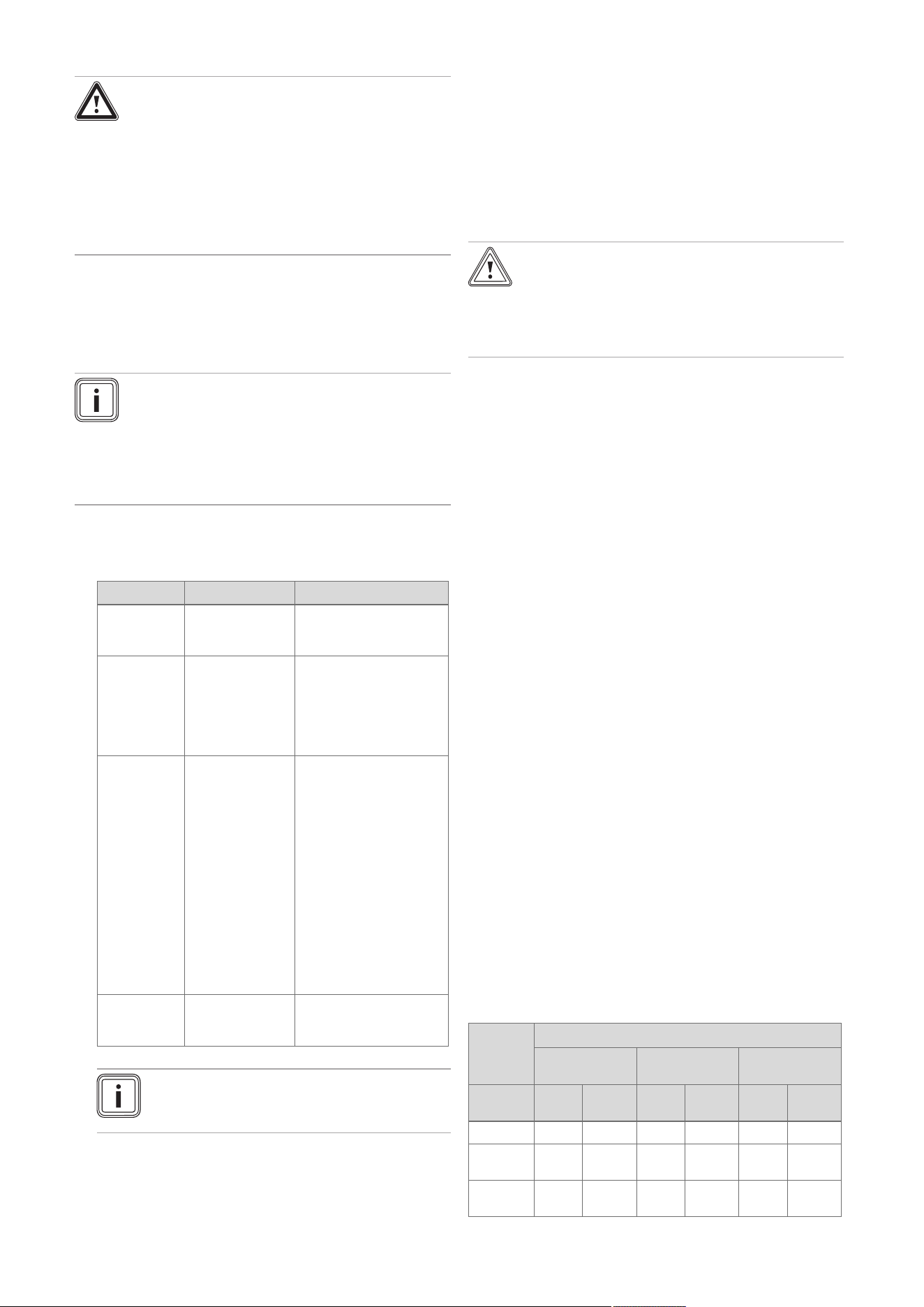
0020244997_07 Installation and maintenance instructions 33
9.6 Performing a gas family check
Danger!
Risk of poisoning!
Inadequate combustion quality (CO), indic-
ated by F.92/93, leads to an increased risk of
poisoning.
▶ Make sure that the fault is completely
eliminated before starting up the product
for continuous operation.
Menu → Installer level → Test programs → Gas family
check
The gas family check checks the product setting with regard
to combustion quality.
Note
If additional condensing boilers are connected to
the same flue pipework in the heating installation,
ensure that none of these condensing boilers are
in operation or start operating throughout the en-
tire test programme, so that the test result is not
distorted.
▶ Perform the gas family check as part of routine product
maintenance work, after replacing components, carrying
out work on the gas route and following gas conversion.
Result Meaning Measure
F.92 See the table of
fault codes in the
appendix
See the table of fault
codes in the appendix
"Successful" Combustion
quality is good.
Unit configur-
ation matches
the specified gas
group.
None
"Warning" Combustion
quality inad-
equate.
CO₂ content is
incorrect.
Start check programme
P.01 and adjust the
CO₂ content with the
adjusting screw in the
Venturi.
If the correct CO₂ con-
tent cannot be set:
Check that the gas re-
strictor is correct (yellow:
G20 natural gas, blue:
G25 natural gas, grey:
Liquid gas) and undam-
aged.
Repeat the gas family
check.
F.93 See the table of
fault codes in the
appendix
See the table of fault
codes in the appendix
Note
It is not possible to perform CO₂ measure-
ments during the gas family check.
9.7 Using check programmes
Menu → Installer level → Test programs → Check pro-
grams
By activating various check programmes, you can trigger
special functions on the product.
Check programmes – Overview (→ Page 63)
9.8 Checking and treating the heating
water/filling and supplementary water
Caution.
Risk of material damage due to poor-qual-
ity heating water
▶ Ensure that the heating water is of suffi-
cient quality.
▶ Before filling or topping up the installation, check the
quality of the heating water.
Checking the quality of the heating water
▶ Remove a little water from the heating circuit.
▶
Check the appearance of the heating water.
▶ If you ascertain that it contains sedimentary materials,
you must desludge the installation.
▶ Use a magnetic rod to check whether it contains mag-
netite (iron oxide).
▶ If you ascertain that it contains magnetite, clean the in-
stallation and apply suitable corrosion-inhibition meas-
ures, or fit a magnetite separator.
▶ Check the pH value of the removed water at 25 °C.
▶ If the value is below 8.2 or above 10.0, clean the installa-
tion and treat the heating water.
▶ Ensure that oxygen cannot get into the heating water.
Checking the filling and supplementary water
▶ Before filling the installation, measure the hardness of the
filling and supplementary water.
Treating the filling and supplementary water
▶ Observe all applicable national regulations and technical
rules when treating the filling and supplementary water.
Provided the national regulations and technical rules do not
stipulate more stringent requirements, the following applies:
You must treat the heating water in the following cases
– If the entire filling and supplementary water quantity dur-
ing the operating life of the system exceeds three times
the nominal volume of the heating installation, or
– If the guideline values listed in the following table are not
met, or
– If the pH value of the heating water is less than 8.2 or
more than 10.0.
Total
heating
output
Water hardness at specific system volume
1)
≤ 20 l/kW
> 20 l/kW
≤ 50 l/kW
> 50 l/kW
kW
ppm
CaCO₃
mol/
m³
ppm
CaCO₃
mol/
m³
ppm
CaCO₃
mol/
m³
< 50 < 300 < 3 200 2 2 0.02
> 50
to ≤ 200
200 2 150 1.5 2 0.02
> 200
to ≤ 600
150 1.5 2 0.02 2 0.02
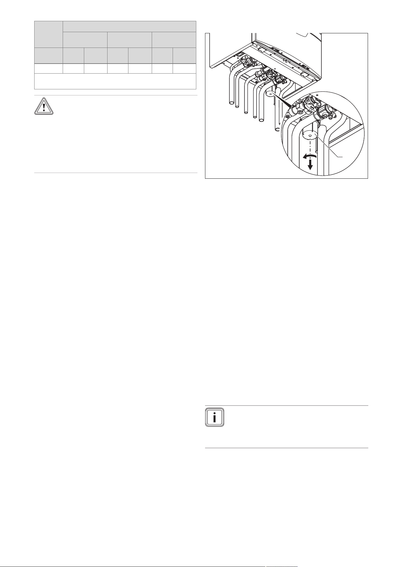
34 Installation and maintenance instructions 0020244997_07
Total
heating
output
Water hardness at specific system volume
1)
≤ 20 l/kW
> 20 l/kW
≤ 50 l/kW
> 50 l/kW
kW
ppm
CaCO₃
mol/
m³
ppm
CaCO₃
mol/
m³
ppm
CaCO₃
mol/
m³
> 600 2 0.02 2 0.02 2 0.02
1) Nominal capacity in litres/heating output; in the case of multi-
boiler systems, the smallest single heating output is to be used.
Caution.
Risk of material damage if the heating
water is treated with unsuitable additives.
Unsuitable additives may cause changes in
the components, noises in heating mode and
possibly subsequent damage.
▶ Do not use any unsuitable antifreeze and
corrosion inhibitors, biocides or sealants.
No incompatibility with our products has been detected to
date with proper use of the following additives.
▶ When using additives, follow the manufacturer's instruc-
tions without exception.
We accept no liability for the compatibility of any additive or
its effectiveness in the rest of the heating system.
Additives for cleaning measures (subsequent
flushing required)
– Adey MC3+
– Adey MC5
– Fernox F3
– Sentinel X 300
– Sentinel X 400
Additives intended to remain permanently in the
installation
– Adey MC1+
– Fernox F1
– Fernox F2
– Sentinel X 100
– Sentinel X 200
Additives for frost protection intended to remain
permanently in the installation
– Adey MC ZERO
– Fernox Antifreeze Alphi 11
– Sentinel X 500
▶ If you have used the above-mentioned additives, inform
the end user about the measures that are required.
▶ Inform the end user about the measures required for frost
protection.
9.9 Filling the condensate trap
1
1. Remove the lower section from the condensate trap
(1).
2. Fill the lower section with water up to 10 mm below the
upper edge.
3. Attach the lower section to the condensate trap.
9.10 Preventing low water pressure
To ensure that the heating installation operates smoothly,
the indicator on the pressure gauge must point to the upper
half of the grey area or to the middle of the bar graph display
in the display (marked by the dashed limit values) when the
heating installation is cold. This corresponds to a filling pres-
sure of between 0.1 MPa and 0.2 MPa (1.0 bar and 2.0 bar).
If the heating installation extends over several storeys,
higher filling pressures may be required to avoid air entering
the heating installation.
If the filling pressure falls below 0.08 MPa (0.8 bar), the
product indicates low pressure by displaying a flashing
pressure value. If the filling pressure falls below 0.05 MPa
(0.5 bar), the product switches off. The display shows F.22.
▶ Top up the heating water to start the product up again.
The pressure value flashes in the display until a pressure of
0.11 MPa (1.1 bar) or higher has been reached.
9.11 Flushing the heating installation for the first
time ("cold")
Note
The complete heating system must be flushed
at least twice: Once with cold water and once
with hot water in accordance with the following
instructions.
1. Check whether all thermostatic radiator valves and
both service valves on the product are open.
2. Connect a hose to the drain valve that is located at the
lowest position in the heating system.
3. Open the radiator valves and the drain valves so that
the water can drain quickly. Start at the next point in
the installation and open the purging valves on the ra-
diators so that the contaminated water can completely
drain.
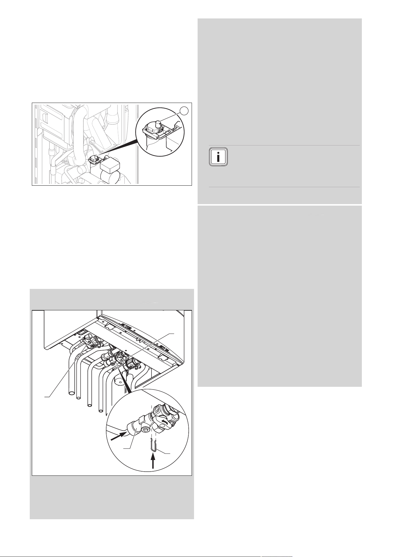
0020244997_07 Installation and maintenance instructions 35
4. Close the draining cocks.
5. Refill the heating system with water.
6. Check that the expansion relief valve of the heating
system is functioning correctly by turning the handle on
the valve.
7. Check the pressure in the heating system and top up
with water if necessary.
8. Close the filling valve and the cold water tap.
9.12 Filling the heating installation
1
1. Flush the heating installation through.
2. Undo the cap of the automatic air vent (1) by one to
two rotations and leave it open, as the product purges
itself via the automatic air vent even in continuous op-
eration.
3. Select the check programme P.06.
◁
The prioritising diverter valve moves to the mid-
position, the pumps do not run and the product
does not switch to heating mode.
4. Observe the information on treating heating water.
(→ Page 33)
5. Check all connections and the entire system for leaks.
Condition: Applies to: Products with integrated domestic hot water genera-
tion
3
1
2
4
▶ Open all radiator valves (thermostatic valves) of the heat-
ing installation.
▶ Fit the double non-return valve (1) of the filling line to the
cold-water isolation valve and secure the valve with the
spring clip (2).
▶ To fill, first open the isolation valve (3).
▶ Open the isolation valve (4) so that the water flows into
the heating system. Fill the heating system.
▶ Purge the lowest radiator until water flows out of the pur-
ging valve without bubbles.
▶ Purge all other radiators until the entire heating system
has been filled with water.
▶ Close all purging valves.
▶ Monitor the rising filling pressure in the heating installa-
tion.
▶ Fill with water until the required filling pressure is
reached.
▶ After filling, close both isolation valves and disconnect
the filling device by removing the double non-return valve
from the cold-water isolation valve.
Note
Both isolation valves must be closed while the
heating system is operating and the filling line
must be removed from the double non-return
valve again.
▶ Check all connections and the entire system for leaks.
Condition: Applies to: Products with heating mode only
▶ Connect the filling/draining cock in the heating installation
to a heating water supply, if possible with the cold water
tap, in accordance with the relevant standards.
▶ Open the heating water supply.
▶ Open all radiator valves (thermostatic valves) of the heat-
ing installation.
▶ If necessary, check that both service valves on the
product are open.
▶ Slowly open the filling/draining cock so that the water
flows into the heating system.
▶ Purge the lowest radiator until water flows out of the pur-
ging valve without bubbles.
▶ Purge all other radiators until the entire heating system
has been filled with water.
▶ Close all purging valves.
▶ Monitor the rising filling pressure in the heating installa-
tion.
▶ Fill with water until the required filling pressure is
reached.
▶ Close the filling/draining cock and the cold water tap.
▶ Check all connections and the entire system for leaks.
9.13 Purging the heating installation
1. Select the check programme P.00.
◁ The product does not start up, the internal pump
operates intermittently and purges either the heat-
ing circuit or the hot water circuit.
◁ The display shows the filling pressure of the heat-
ing installation.
2. Make sure that the filling pressure of the heating install-
ation does not fall below the minimum filling pressure.
36 Installation and maintenance instructions 0020244997_07
– ≥ 0.08 MPa (≥ 0.80 bar)
◁ At the end of the filling procedure, the filling pres-
sure of the heating installation should be at least
0.02 MPa (0.2 bar) above the counter-pressure
of the expansion vessel ("Exp") (P
Installation
≥ P
Exp
+
0.02 MPa (0.2 bar)).
3. If there is still too much air in the heating installation
at the end of the check programme P.00, repeat the
check programme.
9.14 Filling and purging the hot water system
Validity: Product with integrated hot water generation
1. Open the cold water stop valve on the product.
2. Fill the hot water system by opening all the hot water
draw-off valves until water escapes.
9.15 Gas inspection
9.15.1 Checking the factory-set gas setting
Caution.
Risk of material damage caused by mak-
ing unauthorised settings.
▶ Never modify the factory setting of the gas
pressure regulator of the gas valve.
▶ Before you start up the product, compare the gas group
information on the data plate with the gas group available
at the installation site.
Condition: The product design is not compatible with the local gas group
Only Vaillant Service may perform a gas conversion.
If a gas conversion to liquefied petroleum gas has been car-
ried out, the smallest possible partial load is higher than is
shown on the display. The correct values can be found in the
Technical data in the appendix.
▶ Call Vaillant Service (0330 1003 143).
▶ Do not start up the product.
Condition: The product design is compatible with the local gas group
▶ Proceed as described below.
9.15.2 Checking the air/flue pipe/flue gas
recirculation
1. Check the flue gas installation is intact in accordance
with the latest gas safe technical bulletin and informa-
tion supplied in the installation instructions.
2. For extended flue gas installations check for flue gas
recirculation using the air analysis point.
3. Use a flue gas analyser.
4. If you discover unusual levels of CO or CO
2
in the
supply air, search for the leak in the flue system or for
signs of flue gas recirculation.
5. Eliminate the damage properly.
6. Check again whether the supply air contains any un-
usual levels of CO or CO
2
.
7. If you cannot eliminate the damage, do not start up the
product.
9.15.3 Checking the gas flow rate
The gas flow rate has been set during production and does
not require adjustment. With the front casing fitted check the
gas flow rate of the boiler as follows:
▶ Start up the product with the check programme P.01.
▶ In addition, ensure that maximum heat can be dissipated
into the heating system by turning up the room thermo-
stat.
▶ Wait at least 5 minutes until the boiler has reached its
operating temperature.
▶ Ensure that all other gas appliances in the property are
turned off.
▶ Measure the gas flow rate at the gas meter.
▶ Compare the measured values with the corresponding
values in the table.
Qnw from the data
plate
H gas in m³/h
Nom. +5% −10%
15.3 1.62 1.70 1.46
18.4 1.95 2.05 1.76
24.7 2.61 2.74 2.35
25.7 2.72 2.86 2.45
28.6 3.03 3.18 2.73
30.6 3.24 3.40 2.92
35.7 3.78 3.97 3.40
Condition: Gas flow rate not in the permissible range
▶ Check all of the piping and ensure that the gas flow rates
are correct.
▶ Only put the product into operation once the gas flow
rates have been corrected.
Condition: Gas flow rate in the permissible range
▶ End the check programme P.01.
▶ Allow the boiler to cool down by allowing pump overrun to
operate for a minimum of 2 minutes.
▶ Record the boiler maximum gas flow rate onto the
Benchmark Checklist.
9.15.4 Checking the gas flow pressure
1. Ensure that the gas inlet working pressure can be ob-
tained with all other gas appliances in the property
working.
2. Close the gas stopcock.
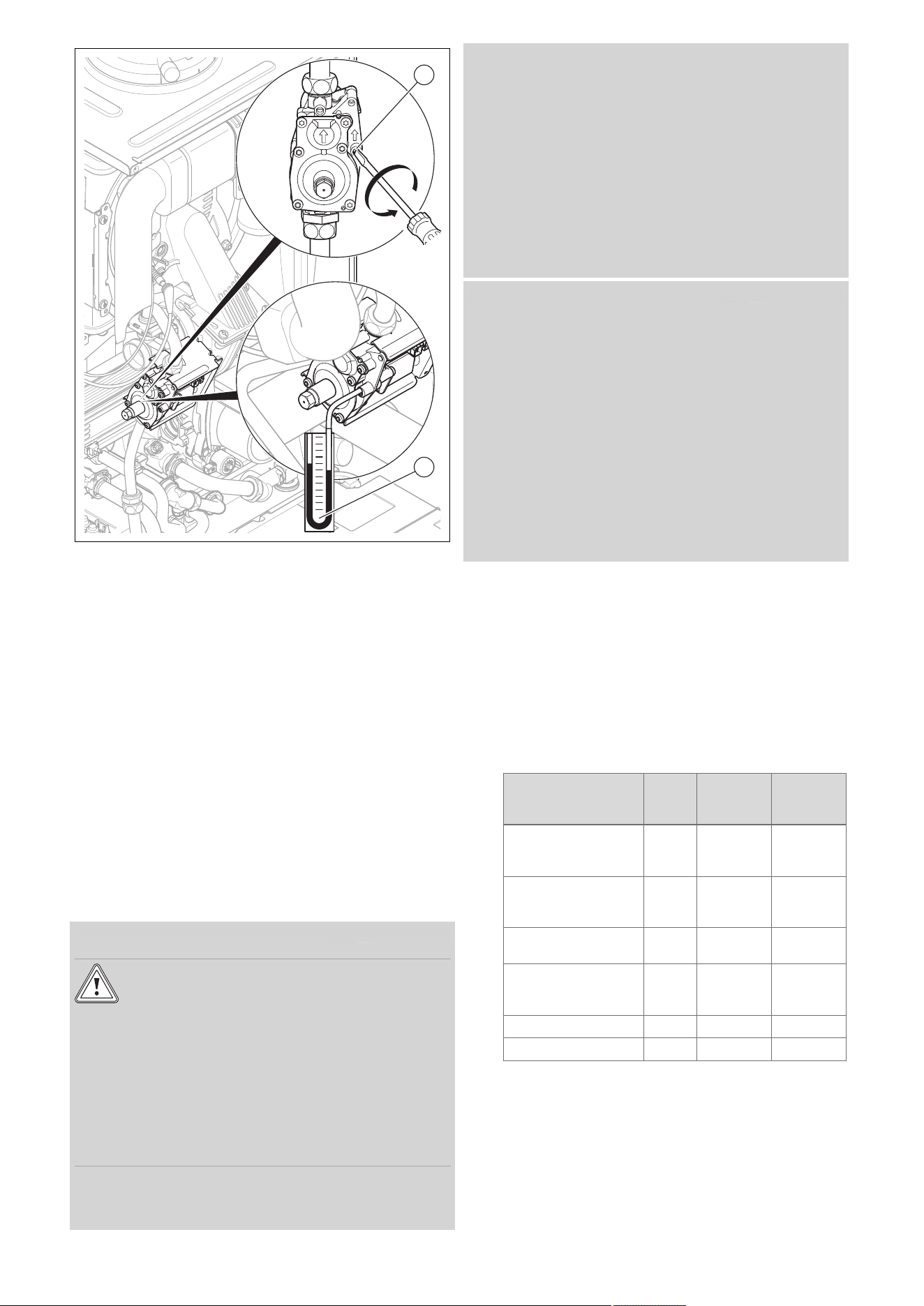
0020244997_07 Installation and maintenance instructions 37
2
1
3. Use a screwdriver to undo the test nipple screw (1)
(lower screw) at the gas valve assembly.
4. Connect a manometer (2) to the test nipple (1).
5. Open the gas stopcock.
6. Start up the product with the check programme P.01.
7. In addition, ensure that maximum heat can be dissip-
ated into the heating system by turning up the room
thermostat.
8. With the boiler operating at full load check that the gas
inlet working pressure at the reference test point com-
plies with the requirements.
– Permissible gas flow pressure for operation with
natural gas H: 1.3 to 2.3 kPa (13.0 to 23.0 mbar)
– Permissible gas flow pressure for operation with
liquefied petroleum gas P: 2.3 to 4.3 kPa (23.0 to
43.0 mbar)
9. Should the pressure recorded at the reference test
point in the boiler be lower than indicated check if there
is any blockage in the pipework or if the pipework is
undersized.
Condition: Gas flow pressure not in the permissible range
Caution.
Risk of material damage and operating
faults caused by incorrect gas connection
pressure.
If the gas connection pressure lies outside
the permissible range, this can cause operat-
ing faults in and damage to the product.
▶ Do not make any adjustments to the
product.
▶ Do not start up the product.
▶ If you cannot correct the failure, notify the gas supply
company and proceed as follows:
▶ End the check programme P.01.
▶ Allow the boiler to cool down by allowing pump overrun to
operate for a minimum of two minutes.
▶ Close the gas stopcock.
▶ Remove the pressure gauge and retighten the sealing
screw (1) for the measuring nipple.
▶ Open the gas stopcock.
▶ Check the test nipple for gas tightness.
▶ Close the gas stopcock.
▶ Install the front casing.
▶ Disconnect the product from the power grid.
▶ You must not start up the boiler.
Condition: Gas flow pressure in the permissible range
▶ End the check programme P.01.
▶ Allow the boiler to cool down allowing pump overrun to
operate for a minimum of two minutes.
▶ Close the gas stopcock.
▶ Remove the pressure gauge and retighten the sealing
screw (1) for the measuring nipple.
▶ Open the gas stopcock.
▶ Check the test nipple for gas tightness.
▶ Install the front casing.
▶ Reset boiler controls for normal operation.
▶ Record the appliance gas inlet working pressure (kPa
resp. mbar) in the Benchmark gas boiler commissioning
checklist.
9.15.5 Checking and, if required, adjusting the
CO₂ content and the CO/CO₂ ratio (air ratio
setting)
1. Start up the product with the check programme P.01.
2. Wait at least five minutes until the product reaches its
operating temperature.
3. Measure the CO₂ and CO/CO₂ content at the flue gas
analysis point.
4. Compare the measured value with the corresponding
value in the table.
Set values Unit Natural
gas H
Liquefied
petroleum
gas P
CO₂ after 5 minutes
in full load mode with
front casing closed
Vol% 9.2 ± 1.0 10.4 ± 0.5
CO₂ after 5 minutes
in full load mode with
front casing removed
Vol% 9.0 ± 1.0 10.2 ± 0.5
Set for Wobbe index
W₀
kWh/m³ 14.09 21.34
O₂ after 5 minutes in
full load mode with
front casing closed
Vol% 4.5 ± 1.8 5.1 ± 0.8
CO value with full load
ppm ≤ 250 ≤ 250
CO/CO₂
≤ 0.0031 ≤ 0.0026
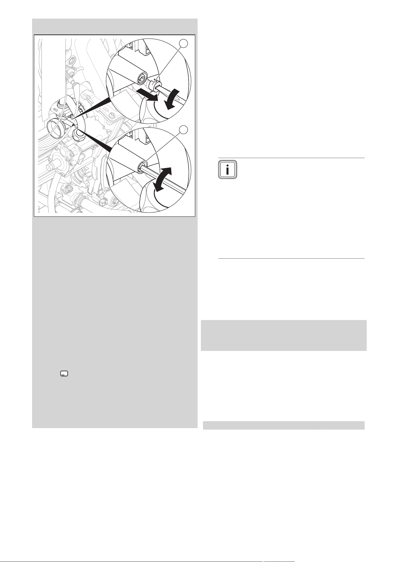
38 Installation and maintenance instructions 0020244997_07
Condition: The CO₂ content must be adjusted
1
2
▶ Pierce the covering cap (1) at the mark using a small flat-
blade screwdriver and unscrew it.
▶ After performing the adjustments, tilt the air intake pipe
back up.
▶ Check the CO₂ content again.
▶ If necessary, repeat the setting process.
▶ Set the CO₂ content (value with front casing removed) by
turning the screw (2).
– Higher CO₂ content: Turn anti-clockwise
– Lower CO₂ content: Turn clockwise
▶ For natural gas only: Only perform the adjustment in in-
crements of 1 turn and wait approx. 1 minute after each
adjustment until the value stabilises.
▶ For liquefied petroleum gas only: Only perform the ad-
justment in small increments (approx. 1/2 turn), and wait
approx. 1 minute after each adjustment until the value
stabilises.
▶ Check the CO₂ content again.
▶ If necessary, repeat the setting process.
▶ Press (Cancel) once the adjustments have been
made.
▶ If an adjustment is not possible in the specified adjust-
ment range, you must not start up the product.
▶ If this is the case, inform Customer Service.
▶ Screw the covering cap back in.
▶
Install the front casing.
9.16 Thoroughly flushing the heating installation
("hot")
1. Operate the appliance until the boiler and the heating
system are up to temperature.
2. Check the heating system for leaks.
3. Connect a hose to the drain valve located at the lowest
position of the heating system.
4. Shut off the boiler, open the drain valve and all purge
valves on the radiators and allow the water to flow out
of the heating system and the boiler quickly and fully.
5. Close the drain valve.
6. Fill the heating system again with water as described in
Filling the heating installation (→ Page 35) and Purging
the heating installation (→ Page 35).
7. Re-fill the system until the system design pressure of
0,1 MPa (1,0 bar) is attained.
Note
The actual reading on the digital pressure
gauge should ideally be 0,05 MPa (0,5 bar)
plus an additional pressure corresponding
to the highest point of the system above
the base of the boiler – 10 m head equals
an additional 1 bar reading on the pressure
gauge. The minimum pressure should not
be less than 0,1 MPa (1 bar) in any install-
ation. If the system is to be treated with an
inhibitor it should be applied at this stage in
accordance with the manufacturer’s instruc-
tions.
8. Install the front casing.
9.17 Checking leak-tightness
▶ Check the gas pipe, the heating circuit and the hot water
circuit for leak-tightness.
▶ Check that the air/flue pipe has been installed correctly.
Condition: Room-sealed operation
▶ Check whether the vacuum chamber has been closed
tightly.
9.17.1 Checking the heating mode
1. Make sure that there is a heat requirement.
2. Call up Live monitor.
◁ If the product is working correctly, the display
shows S.04.
9.17.2 Checking the hot water generation
Validity: Product with integrated hot water generation
1. Open a hot water valve all the way.
2. Call up Live monitor.
◁ If the hot water generation is working correctly,
S.14 appears in the display.
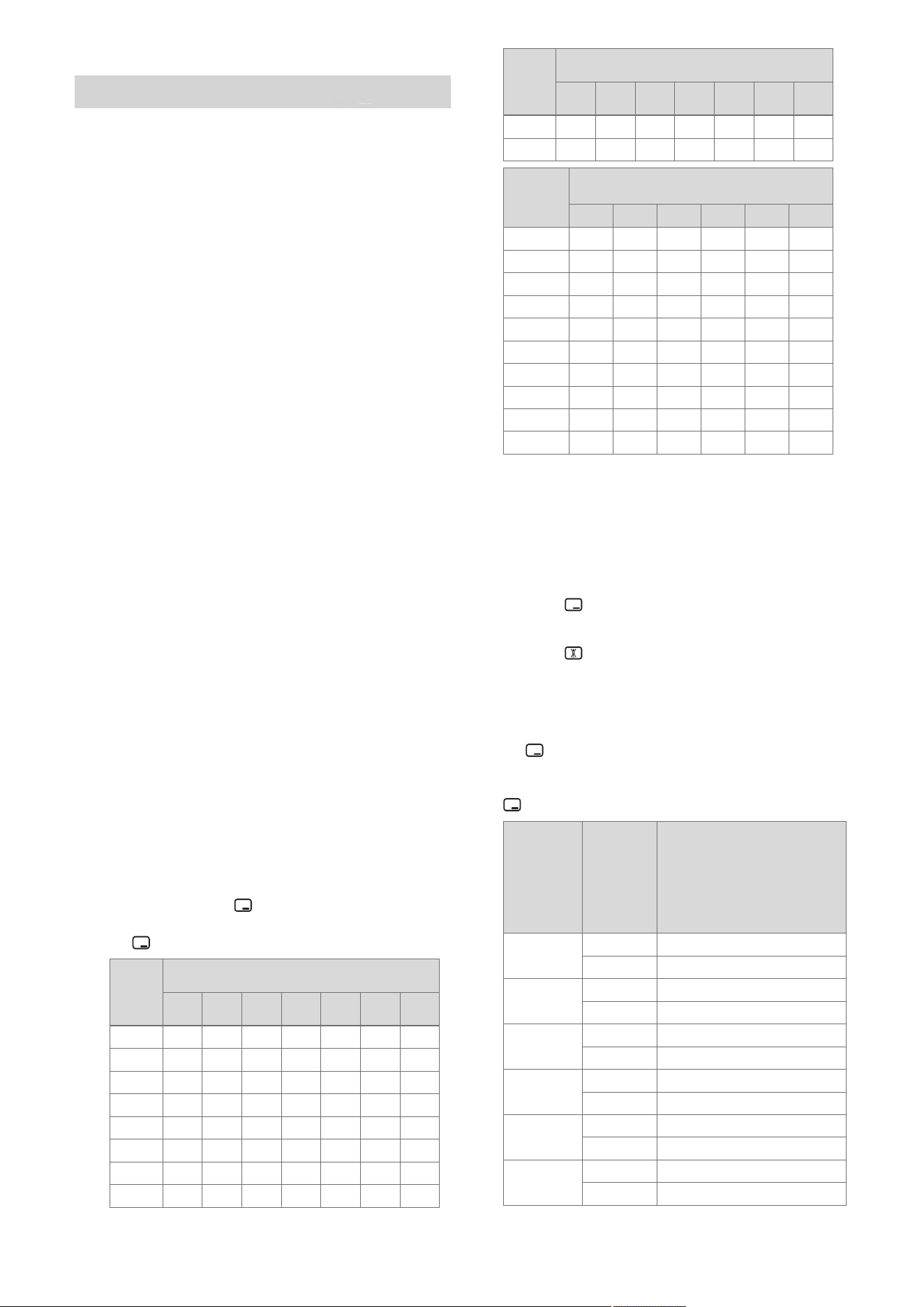
0020244997_07 Installation and maintenance instructions 39
9.17.3 Checking the domestic hot water generation
Validity: Product with hot water generation through external domestic hot
water cylinder
1. Ensure that the cylinder charging mode is requesting
heat.
2. Call up Live monitor.
◁ If the cylinder is charged correctly, the display
shows S.24.
3. If you have connected a Vaillant eBUS control which
can be used to set the domestic hot water temperature,
set the domestic hot water temperature on the boiler to
the maximum possible temperature.
4. Adjust the target temperature for the connected do-
mestic hot water cylinder to the eBUS control.
◁ The product adopts the target temperature that is
set on the eBUS control.
10 Adapting the unit to the heating
installation
To reset the most important system parameters, use the
Unit configuration menu item.
Menu → Installer level → Appliance config.
Or manually relaunch the installation assistant.
Menu → Installer level → Start inst. assistant
You can find setting options in the Diagnostics menu.
Menu → Installer level → Diagnostics menu
Overview of diagnostics codes (→ Page 54)
10.1 Burner anti-cycling time
To prevent frequent switching on and off of the burner and
thus prevent energy losses, an electronic restart lockout
is activated for a specific period each time the burner is
switched off. The burner anti-cycling time is only active
for the heating mode. Hot water handling during a burner
anti-cycling time does not affect the time function element
(default setting: 20 mins).
10.1.1 Setting the burner anti-cycling time
1. Navigate to Menu → Installer level → Diagnostics
menu → D.002 Max. anti-cycl. time: Heating and
confirm by pressing .
2. Set the burner anti-cycling time and confirm by press-
ing .
T
Flow
(tar-
get)
[°C]
Set maximum burner anti-cycling time [min]
1 5 10 15 20 25 30
30 2.0 4.0 8.5 12.5 16.5 20.5 25.0
35 2.0 4.0 7.5 11.0 15.0 18.5 22.0
40 2.0 3.5 6.5 10.0 13.0 16.5 19.5
45 2.0 3.0 6.0 8.5 11.5 14.0 17.0
50 2.0 3.0 5.0 7.5 9.5 12.0 14.0
55 2.0 2.5 4.5 6.0 8.0 10.0 11.5
60 2.0 2.0 3.5 5.0 6.0 7.5 9.0
65 2.0 1.5 2.5 3.5 4.5 5.5 6.5
T
Flow
(tar-
get)
[°C]
Set maximum burner anti-cycling time [min]
1 5 10 15 20 25 30
70 2.0 1.5 2.0 2.5 2.5 3.0 3.5
75 2.0 1.0 1.0 1.0 1.0 1.0 1.0
T
Flow
(target)
[°C]
Set maximum burner anti-cycling time
[min]
35 40 45 50 55 60
30 29.0 33.0 37.0 41.0 45.0 49.5
35 25.5 29.5 33.0 36.5 40.5 44.0
40 22.5 26.0 29.0 32.0 35.5 38.5
45 19.5 22.5 25.0 27.5 30.5 33.0
50 16.5 18.5 21.0 23.5 25.5 28.0
55 13.5 15.0 17.0 19.0 20.5 22.5
60 10.5 11.5 13.0 14.5 15.5 17.0
65 7.0 8.0 9.0 10.0 11.0 11.5
70 4.0 4.5 5.0 5.5 6.0 6.5
75 1.0 1.0 1.0 1.0 1.0 1.0
10.1.2 Resetting the remaining burner anti-cycling
time
1. Alternatives 1:
▶ Navigate to Menu → Reset anti-cycl. time.
◁ The current burner anti-cycling time appears in
the display.
▶ Press to reset the burner anti-cycling time.
1.
Alternatives 2:
▶ Press .
10.2 Setting the maintenance interval
1. Navigate to Menu → Installer level → Diagnostics
menu → D.084 Maintenance in and confirm by press-
ing .
2. Set the maintenance interval (operating hours) until the
next maintenance work is due and confirm by pressing
.
Heat de-
mand
Number
of per-
sons
Guideline value for burner
operating hours until the
next inspection/maintenance
work is due for an average
operating time of one year
(dependent upon the system
type)
5.0 kW
1 ‑ 2 1050 h
2 ‑ 3 1150 h
10.0 kW
1 ‑ 2 1500 h
2 ‑ 3 1600 h
15.0 kW
2 ‑ 3 1800 h
3 ‑ 4 1900 h
20.0 kW
3 ‑ 4 2600 h
4 ‑ 5 2700 h
25.0 kW
3 ‑ 4 2800 h
4 ‑ 6 2900 h
> 27.0 kW
3 ‑ 4 3000 h
4 ‑ 6 3000 h
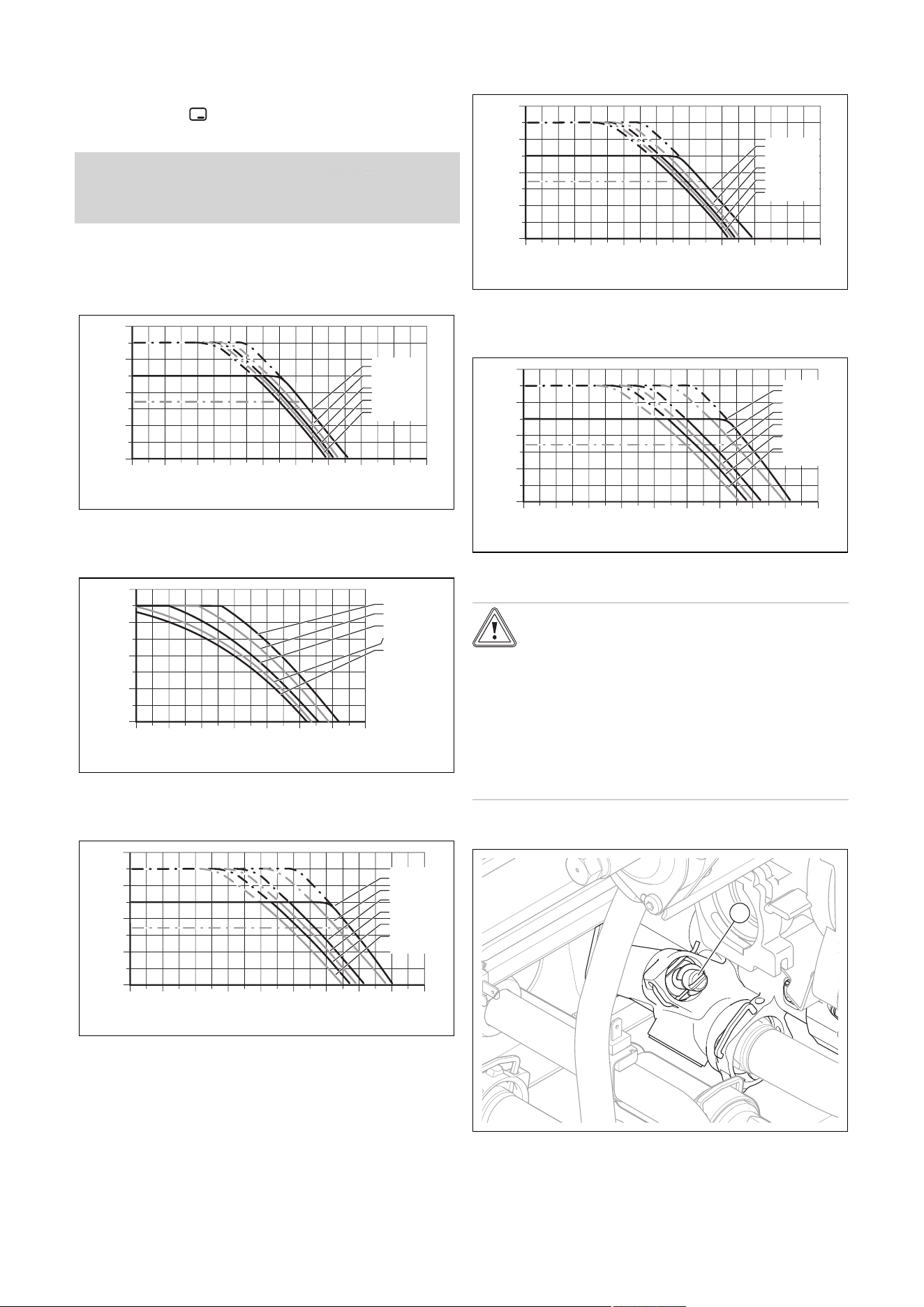
40 Installation and maintenance instructions 0020244997_07
10.3 Setting the pump output
1. Navigate to Menu → Installer level → Diagnostics
menu → D.014 Pump speed target value and confirm
by pressing .
2. Set the required pump output.
Condition: Low loss header installed
▶ Switch off the speed regulation and set the pump output
to a fixed value.
10.3.1 Remaining feed head of the pump
10.3.1.1 Pump characteristic line for VU 126, VU 156,
VU 186
400
300
200
100
0
0 200 400 600 800 1000 1200 1600
1800
1400
Flow rate
[
l/hr
]
Remaining feed head
[hPa]
100% PWM
85%
70%
60%
53%
10.3.1.2 Pump characteristic line for VU 246, VUW
196, VUW 256
0
400
300
200
100
0
50
150
250
350
200 400 600 800 1000 1200 1400
Remaining feed head
[hPa]
Flow rate
[
l/hr
]
100% PWM
80%
70%
60%
53%
10.3.1.3 Pump characteristic line for VU 306, VUW
306, VUW 356
400
300
200
100
0
0 200 400 600 800 1000 1200 1600
1800
1400
Flow rate
[
l/hr
]
Remaining feed head
[hPa]
100% PWM
85%
70%
60%
53%
10.3.1.4 Pump characteristic line for VUW 246, VUW
326
400
300
200
100
0
0 200 400 600 800 1000 1200 1600
1800
1400
Remaining feed head
[hPa]
Flow rate
[
l/hr
]
100% PWM
85%
70%
60%
53%
10.3.1.5 Pump characteristic line for VU 376, VU 386,
VUW 286, VUW 386
400
300
200
100
0
0 200 400 600 800 1000 1200 1600
1800
1400
Remaining feed head
[hPa]
Flow rate
[
l/hr
]
Minimum
with Auto
100% PWM
85%
70%
60%
53%
10.4 Setting the bypass valve
Caution.
Risk of material damage caused by incor-
rect setting of the high-efficiency pump
If the pressure at the bypass valve is in-
creased (by turning it clockwise) and the
pump output is set to less than 100%, the
product may not operate correctly.
▶ In this case, set the pump output to
5 = 100% using diagnostics code D.014.
▶ Remove the front casing. (→ Page 23)
1
▶ Regulate the pressure using the adjusting screw (1).

0020244997_07 Installation and maintenance instructions 41
Position of the
adjusting screw
Pres-
sure
in MPa
(mbar)
Notes/application
Right-hand stop
(turned all the
way down)
0.035
(350)
If the radiators do not heat
up sufficiently at the default
setting. In this case, you
must set the pump to the
maximum speed.
Mid-position
(5 turns to the
left)
0.025
(250)
Default setting
5 further turns to
the left from the
mid-position
0.017
(170)
If noises are produced in
the radiators or radiator
valves
▶ Install the front casing.
11 Handing over to the end user
▶ At the time of commissioning complete all relevant sec-
tions of the Benchmark commissioning checklist, located
at the rear of this document.
▶ For IE: Complete a “Declaration of Conformity” to indicate
compliance to I.S. 813. An example of this is given in the
current edition of I.S. 813.
▶ When you have finished the installation, affix the en-
closed sticker (which requests that the user reads the
instructions) to the front of the product in the end user's
language.
▶ Draw attention, to the current issue of the Gas Safety
(Installation and Use) Regulations, Section 35, which
imposes a duty of care on all persons who let out any
property containing a gas appliance in the UK.
▶ Explain to the end user how the safety devices work and
where they are located.
▶ Inform the end user how to handle the product.
▶ In particular, draw attention to the safety warnings that
the end user must follow.
▶ Inform the end user that they must have the product
maintained in accordance with the specified intervals.
▶ Pass all of the instructions and documentation for the
product to the end user for safe-keeping.
▶ Inform the end user about measures taken to ensure
the supply of combustion air and flue gas guiding, and
instruct the operator that he must not make any changes.
▶ Inform the end user that they must not store or use explo-
sive or highly flammable substances (such as petrol, pa-
per or paint) in the installation room of the product.
▶ Complete and sign off the Benchmark commissioning
check list.
▶ Complete and sign off the guarantee documentation.
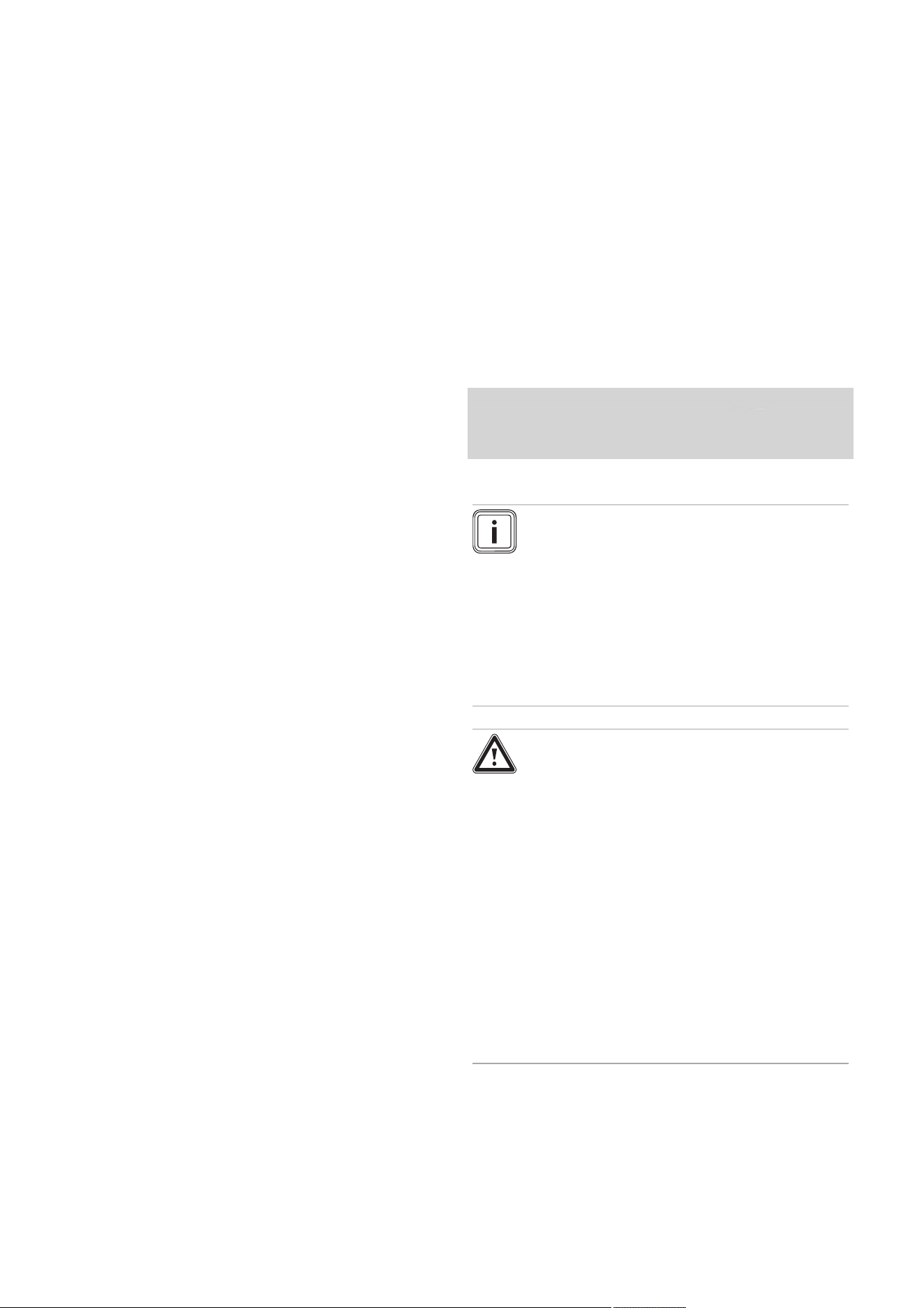
42 Installation and maintenance instructions 0020244997_07
12 Inspection and maintenance
12.1 Complete Service Interval Record section
▶ After servicing, complete the relevant Service Interval
Record section of the Benchmark Checklist located on
the inside back pages of this document.
12.2 Using original seals
If you replace components, use only the enclosed original
seals; additional sealing materials are not required.
12.3 Inspection and maintenance
▶ You must carry out an annual inspection of the product.
The annual inspection can be effectively performed
without removing components by requesting data from
the DIA system, carrying out the simple visual checks in-
dicated in the table in the appendix and performing a flue
gas measurement. The maintenance intervals and their
scope are determined by the heating engineer based on
the condition of the boiler found during the inspection. All
inspection and maintenance work should be performed in
the order specified in the table in the appendix.
During any inspection and maintenance or after change
of parts of the combustion circuit, the following must be
checked:
– The boiler has been installed in accordance with the rel-
evant installation instructions.
– The integrity of the flue gas installation and flue seals is
in accordance with the relevant flue installation instruc-
tions enclosed.
– Visual, the integrity of the boiler combustion circuit and
relevant seals (paying particular attention to the burner
door seal).
– The gas inlet working pressure at maximum rate.
– The gas flow rates.
– Correctness of electrical, water and gas connections.
– Correctness of the water pressure.
– The condition of the whole system, in particular the con-
dition of radiator valves, evidence of leakage from the
heating system and dripping taps.
▶ Correct any faults before proceeding.
12.4 Preparing the maintenance work
1. Switch off the product.
2. Disconnect the product from the power grid.
3. Remove the front casing. (→ Page 23)
4. Close the gas stopcock.
5. Close the service valves in the heating flow and in the
heating return.
6. Close the service valve in the cold water pipe.
7. Drain the product to clean hydraulic components
(→ Page 44).
8. Ensure that water does not drip on live components
(e.g. the electronics box).
9. Use only new seals and o'ring. Do not use additional
compounds.
12.5 Function menu
Menu → Installer level → Test programs → Function menu
The function menu allows you to actuate and test individual
components in the heating installation.
Function menu – Overview (→ Page 63)
12.6 Electronics self-test
Menu → Installer level → Test programs → Electronics
self-test
You can use the electronics self-test to check the PCB.
12.7 Checking the electrical plug connections
1. Use the main switch to switch off the product.
2. Disconnect the product from the power supply by
switching off the circuit breaker in the case of a fixed
connection.
Condition: Product disconnected from the power supply
▶ Check that the electrical plug connections and connec-
tions are working correctly and are connected correctly.
12.8 Removing the compact thermal module
Note
The compact thermal module consists of five main
components:
– Speed-regulated fan,
– Gas valve assembly including support plate,
– Venturi incl. mass flow sensor and gas connec-
tion pipe,
– Burner flange,
– Premix burner.
Danger!
Risk of death and risk of material damage
caused by hot flue gas.
The seal, insulating mat and self-locking nuts
on the burner flange must not be damaged.
Otherwise, hot flue gases may escape and
cause personal injury and material damage.
▶ Replace the seal each time you open the
burner flange.
▶ Replace the self-locking nuts on the
burner flange each time you open the
burner flange.
▶ If the insulating mat on the burner flange
or on the back wall of the heat exchanger
shows signs of damage, replace the insu-
lating mat.
1. Switch off the product using the on/off button.
2. Close the gas stopcock.
3. Remove the front casing. (→ Page 23)
4. Hinge the electronics box forwards.
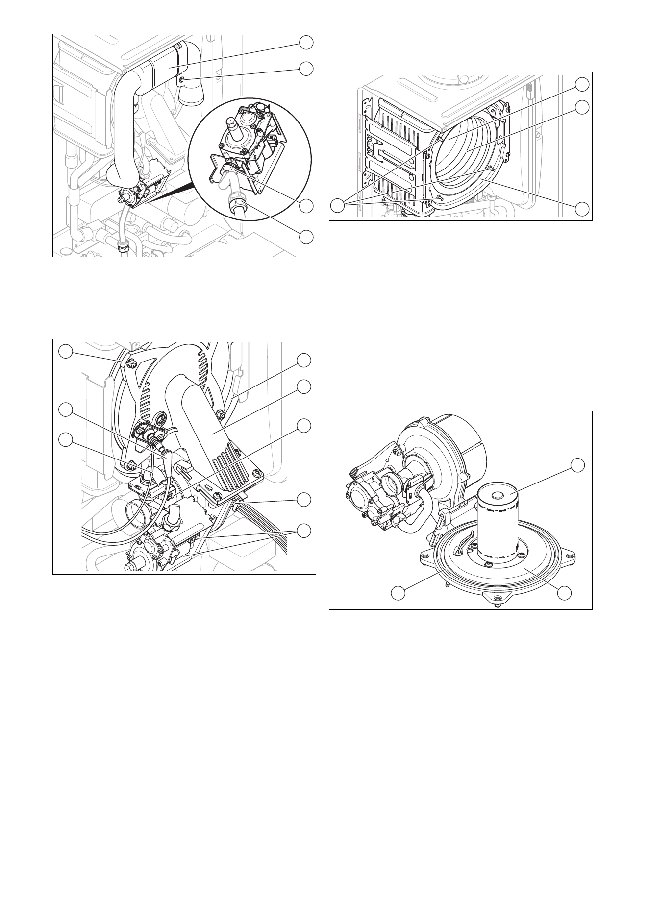
0020244997_07 Installation and maintenance instructions 43
1
1
2
3
4
5. Unscrew the retaining screw (2) and remove the air
intake pipe (1) from the intake stub.
6. Unscrew either the union nut on the gas valve as-
sembly (3) or the union nut (4) between the flexible gas
pipe and the fixed gas pipe.
1
8
7
6
2
3
4
5
7. Remove the plugs of the ignition line (7) and of the
earth connection (6) from the ignition electrode.
8. Remove the plug (4) from the fan motor by pushing in
the latching lug.
9. Remove the three plugs from the gas valve assembly
(5).
10. Remove the plug from the Venturi (3) by pushing in the
latching lug.
11. Release the cable harness from the clip on the gas
valve assembly retainer.
12. Unscrew the four nuts (8).
13. Remove the entire compact thermal module (2) from
the heat exchanger (1).
14. Check the burner and the heat exchanger for damage
and dirt.
15. If necessary, clean or replace the components accord-
ing to the following sections.
16. Fit a new burner flange seal.
17. Check the insulating mat on the burner flange and on
the back panel of the heat exchanger. If you notice any
signs of damage, replace the relevant insulating mat.
12.9 Cleaning the heat exchanger
1. Protect the open electronics box from spraying water.
2
3
4
1
2. Never undo the four nuts on the stud bolt (1) or tighten
them.
3. Clean the spiral immersion heater (3) of the heat ex-
changer (4) using water or, if required, vinegar (to a
maximum of 5% acid). Allow the vinegar to act on the
heat exchanger for 20 minutes.
4. Rinse away any loose dirt with a sharp jet of water
or use a plastic brush. Do not point the jet of water
directly at the insulating mat (2) on the rear of the heat
exchanger.
◁ The water flows out of the heat exchanger through
the condensate trap.
12.10 Checking the burner
2 2
1
1. Check the surface of the burner (1) for damage. If you
see any damage, replace the burner.
2. Fit a new burner flange seal (3).
3. Check the insulating mat (2) on the burner flange. If
you notice any signs of damage, replace the insulating
mat.
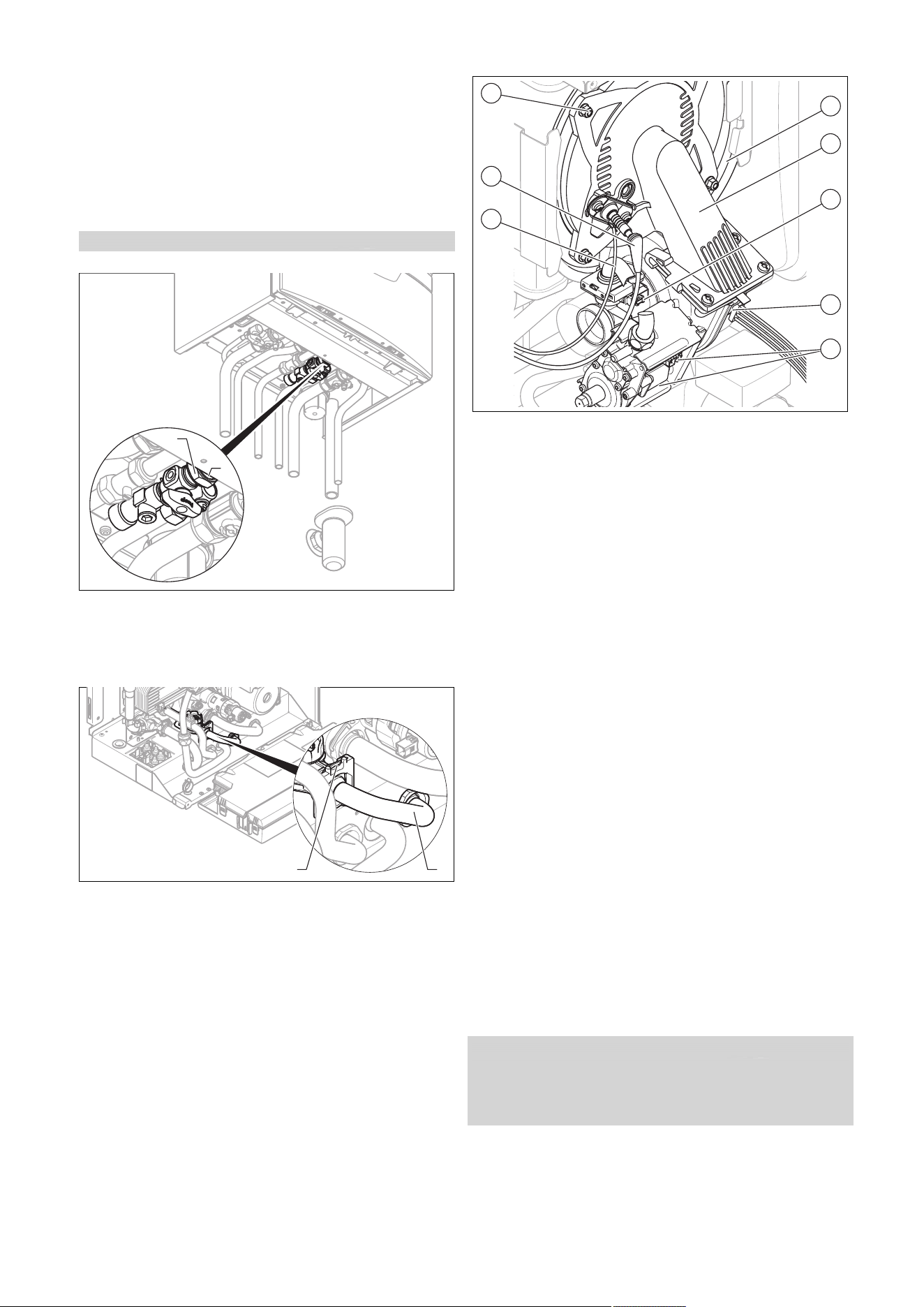
44 Installation and maintenance instructions 0020244997_07
12.11 Cleaning the condensate trap
1. Remove the lower section from the condensate trap
(1).
2. Flush out the lower section with water.
3. Fill the lower section with water up to about 10 mm
below the upper edge.
4. Attach the lower section to the condensate trap.
12.12 Cleaning the strainer in the cold water inlet
Validity: Product with integrated hot water generation
1
2
1. Close the cold-water isolation valve.
2. Drain the product on the domestic hot water side.
3. Unscrew the union nut (2) and the lock nut (1) from the
product's housing.
2
1
4. Hinge the electronics box forwards.
5. Remove the clamp (2).
6. Remove the pipe (1) from the product.
7. Rinse the strainer under a jet of water, holding it
against the direction of flow.
8. If the strainer is damaged or it can no longer be
cleaned sufficiently, you must replace the strainer.
9. Refit the pipe.
10. Reinsert the clamp.
11. Always use new seals and retighten the union nuts and
the lock nut.
12. Open the cold-water isolation valve.
12.13 Installing the compact thermal module
1
8
7
6
2
3
4
5
1. Connect the compact thermal module (2) to the heat
exchanger (1).
2. Tighten the four new nuts (8) across the diagonal until
the burner flange fits closely and uniformly onto the
mating surfaces.
– Tightening torque:6 Nm, if a torque spanner is
available
3. Reconnect the plugs (3) to (7).
4. Connect the gas pipe using a new seal. In the process,
secure the gas pipe against twisting.
5. Open the gas stopcock.
6. Make sure that there are no leaks.
7. Check that the sealing ring in the air intake pipe is posi-
tioned correctly in the seal seat.
8. Reconnect the air intake pipe to the intake stub.
9. Secure the air intake pipe with the retaining screw.
10. Check the gas flow pressure.
12.14 Draining the product
1. Close the service valves of the product.
2. Start the check programme P.06 (prioritising diverter
valve mid-position).
3. Open the drain valves.
4. Make sure that the cap of the automatic air vent on
the internal pump is open so that the product can be
drained fully.
12.15 Checking the pre-charge pressure for the
internal expansion vessel
1. Close the service valves and drain the product.
2. Measure the pre-charge pressure of the expansion
vessel at the vessel valve.
Condition: Pre-charge pressure < 0.075 MPa (0.75 bar)
▶ Ideally, you should top up the expansion vessel with ni-
trogen. Otherwise, top it up with air. Ensure that the drain
valve is open when topping up.
3. If water escapes from the valve of the expansion
vessel, you must replace the expansion vessel.
(→ Page 49)
4. Fill the heating installation. (→ Page 35)

0020244997_07 Installation and maintenance instructions 45
5. Purge the heating installation. (→ Page 35)
12.16 Checking the filling pressure of the heating
installation
1. Check the filling pressure of the heating installation, top
it up with heating water, if necessary, and purge it.
2. Fill the heating installation. (→ Page 35)
3. Purge the heating installation. (→ Page 35)
12.17 Checking the quality of the heating water
▶ Check the quality of the heating water: Clarity (clouding),
correct inhibitor and pH value. (→ Page 33)
12.18 Completing inspection and maintenance
work
▶ Start a test operation after the maintenance.
▶ Check the heating mode and, if required, the domestic
hot water generation (if available).
▶ Carry out a gas family check. (→ Page 33)
▶ Check the gas flow pressure. (→ Page 36)
▶ Check and, if required, adjust the CO₂ content and the
CO/CO₂ ratio (air ratio setting). (→ Page 37)
▶ If required, reset the maintenance interval. (→ Page 39)
▶ Install the front casing.
▶ Fill out the relevant Service Record section in the Bench-
mark Checklist.
12.19 Checking the product for leak-tightness
▶ Check that the product is leak-tight. (→ Page 38)
13 Troubleshooting
13.1 Checking service messages
appears if you have set a maintenance interval, for ex-
ample, and this has passed or a service message is issued.
The product is not in fault mode.
▶ Navigate to Menu → Live monitor and confirm by press-
ing .
Condition: S.40 is displayed
The product is in Comfort protection mode. The product con-
tinues to run with restricted comfort after it has detected a
fault.
▶ To establish whether or not a component is defective,
read the fault memory. (→ Page 45)
Note
If no fault message is present, the product will
automatically switch back to normal operating
mode after a certain time.
13.2 Eliminating faults
▶ If fault messages (F.XX) occur, eliminate the faults by
checking the table in the appendix or using the function
menu or the check programmes.
Overview of fault codes (→ Page 60)
Function menu – Overview (→ Page 63)
Check programmes – Overview (→ Page 63)
If several faults occur at the same time, the display shows
the corresponding fault messages for two seconds each in
alternation.
▶ Press (max. three times) to restart the product.
▶ If you are unable to eliminate the fault and the fault re-
curs despite reset attempts, contact customer service.
13.3 Calling up and clearing the fault memory
The last 10 fault messages are stored in the fault memory.
▶ Navigate to the Fault list menu.
◁ The display shows the number of faults that have
occurred, the fault numbers and the corresponding
plain text display.
▶ Press or to call up individual fault messages.
▶ Press twice to delete the fault list.
13.4 Resetting parameters to factory settings
1. Navigate to Menu → Installer level → Diagnostics
menu → D.096 Reset to factory settings? and con-
firm by pressing .
2. Set the diagnostics code to 1, and confirm by pressing
.
13.5 Preparing the repair work
1. Decommission the product.
2. Disconnect the product from the power grid.
3. Remove the front casing. (→ Page 23)
4. Close the gas stopcock.
5. Close the service valves in the heating flow and in the
heating return.
6. Close the service valve in the cold water pipe.
7. Drain the product if you want to replace water-carrying
components of the product.
8. Ensure that water does not drip on live components
(e.g. the electronics box).
9. Use only new seals.
13.5.1 Procuring spare parts
The original components of the product were also certified
by the manufacturer as part of the declaration of conformity.
If you use other, non-certified or unauthorised parts during
maintenance or repair work, this may void the conformity of
the product and it will therefore no longer comply with the
applicable standards.
We strongly recommend that you use original spare parts
from the manufacturer as this guarantees fault-free and safe
operation of the product. To receive information about the
available original spare parts, contact the contact address
provided on the back page of these instructions.
▶ If you require spare parts for maintenance or repair
work, use only the spare parts that are permitted for the
product.
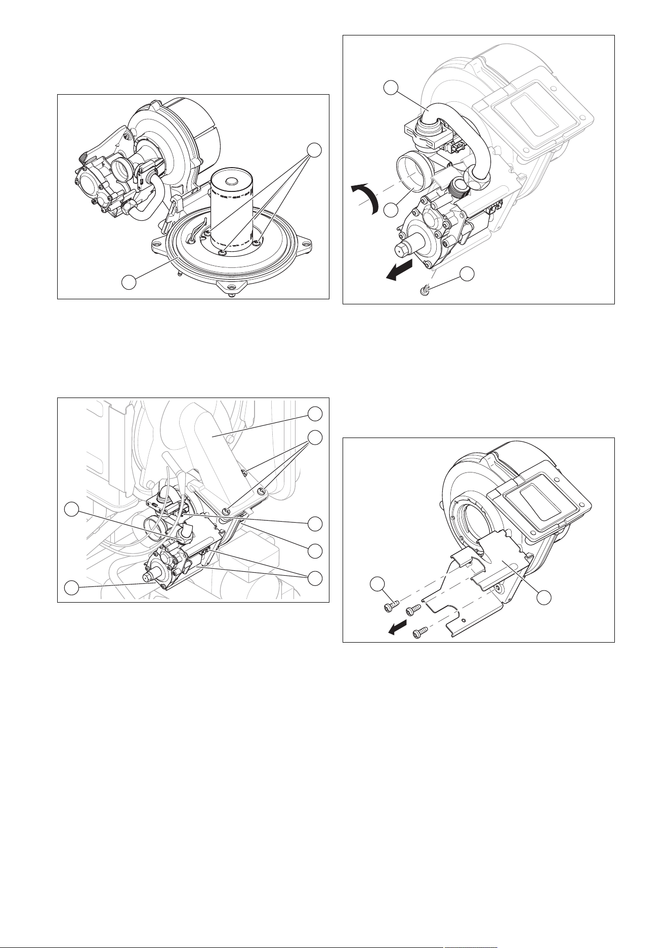
46 Installation and maintenance instructions 0020244997_07
13.6 Replacing defective components
13.6.1 Replacing the burner
1. Remove the compact thermal module. (→ Page 42)
2
1
2. Undo the four screws (1) on the burner.
3. Remove the burner.
4. Install a new seal (2) on the new burner.
5. Install the compact thermal module. (→ Page 44)
13.6.2 Replacing the fan
1
2
3
4
5
6
7
1. Remove the air intake pipe.
2. Remove the three plugs from the gas valve assembly
(5 ).
3. Remove the plug from the sensor on the Venturi (3) by
pushing in the latching lug.
4. Remove the plug/plugs (4) (depending on the unit
design) from the fan motor by pushing in the latching
lug in each case.
5. Unscrew the two union nuts (7) and (6) on the gas
valve assembly. Use an open-ended spanner to coun-
terhold the opposite side of the gas valve assembly
when unscrewing.
6. Unscrew the three screws (2) between the mixture pipe
(1) and the fan flange.
1
3
2
7. Remove the entire unit comprising the fan, Venturi and
gas valve assembly from the product.
8. Unscrew the gas valve assembly fixing screw (2) from
the retainer.
9. Remove the gas valve assembly from the retainer.
10. Remove the Venturi (3), including the gas connection
pipe (1), from the fan by turning the bayonet fitting on
the Venturi anti-clockwise as far as it goes and remov-
ing it straight from the fan.
1
2
11. Remove the gas valve assembly retainer (1) from the
fan by unscrewing the three screws (2).
12. Replace the defective fan.
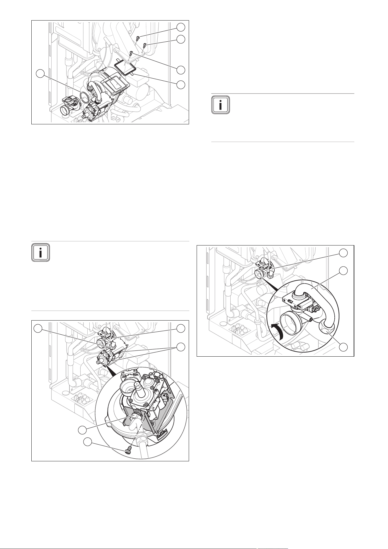
0020244997_07 Installation and maintenance instructions 47
2
1
3
4
5
13. Refit the components in the reverse order. New seals
(4) and (5) must be used for this. Pay attention to the
order in which the three screws between the fan and
the mixture pipe are screwed in, as per the numbering
(1), (2) and (3).
14. Screw the flexible gas supply to the gas valve
assembly. Use new seals for this.
15. When tightening the union nut on the gas valve as-
sembly, use an open-ended spanner to counterhold
the opposite side of the gas valve assembly.
16. Perform a gas family check after installing the new fan.
(→ Page 33)
13.6.3 Replacing the gas valve assembly
Note
To replace the gas valve assembly, you will need
a Torx T20. To replace the gas valve assembly
directly from the front, you will need an offset
screwdriver or a Torx T20 socket. If you do not
have access to an offset screwdriver or the like,
you must first remove the entire unit comprising
the fan with gas valve assembly before you can
remove the gas valve assembly from the retainer.
1
2
3
4
5
1. Remove the air intake pipe.
2. Remove the three plugs from the gas valve assembly
(2).
3. Remove the plug from the sensor on the Venturi (1) by
pushing in the latching lug.
4. Unscrew the two union nuts (5) and (4) on the gas
valve assembly. Use an open-ended spanner to coun-
terhold the opposite side of the gas valve assembly (4)
and (5) when unscrewing.
5. Either remove the unit comprising the fan with gas
valve assembly (Replacing the fan (→ Page 46)), or
use an offset screwdriver or Torx T20 socket to un-
screw the fixing screw of gas valve assembly (3) from
the retainer.
Note
The screw in the gas valve assembly
retainer secures the gas valve assembly
against turning and must be screwed back
in once the gas valve assembly has been
replaced.
6. Remove the gas valve assembly from the retainer.
7. Reinstall the new gas valve assembly in the reverse
order. Use new seals for this.
8. When tightening the union nuts on the gas valve as-
sembly, use an open-ended spanner to counterhold
the opposite side of the gas valve assembly (4) and
(5).
9. After installing the new gas valve assembly, perform
a leak-tightness test (→ Page 38), gas family check
(→ Page 33) and gas setting (→ Page 36).
13.6.4 Replacing the Venturi
1
2
3
1. Remove the air intake pipe.
2. Remove the plug from the sensor on the Venturi (1) by
pushing in the latching lug.
3. Unscrew the union nuts (3) of the gas connection pipe
(2) on the gas valve assembly.
4. Remove the Venturi, including the gas connection pipe,
from the fan by turning the bayonet fitting on the Ven-
turi anti-clockwise as far as it goes and removing it
straight from the fan.
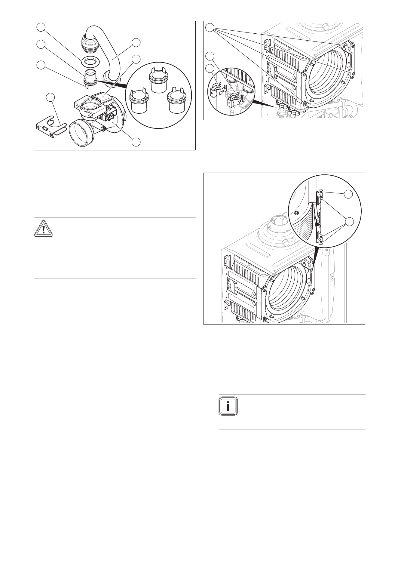
48 Installation and maintenance instructions 0020244997_07
1
2
3
4
5
6
7
5. Remove the gas connection pipe (1) from the Venturi
(3) by removing the clamp (4) and pulling the gas con-
nection pipe out vertically. Dispose of the seal (7).
6. Pull the gas injector (6) straight off, and keep it for re-
use.
7. Check whether the Venturi is free of residue at the gas
inlet side.
Caution.
Risk of material damage to the product.
Lubricant can block function-related channels
in the Venturi.
▶ Do not use lubricant when installing the
gas restrictor.
8. Ensure that you use the correct gas injector (colour
coding and position of pins on the underside of the gas
injector). The colour of the gas injector must match the
colour of the coding resistor on the PCB.
9. Insert the gas injector for the gas group in question
into the new Venturi (yellow: G20 natural gas, grey:
Liquefied petroleum gas).
10. When inserting the gas injector, ensure that the gas in-
jector is correctly aligned using the indicated position
marks on the upper side of the Venturi and also the po-
sitioning pins (5) on the underside of the gas injector.
11. Refit the components in the reverse order. Use new
seals for this.
12. After installing the new Venturi, carry out a gas setting.
(→ Page 36)
13. If you cannot adjust the CO2 content, the gas injector
has been damaged during installation. In this case,
replace the gas injector with an appropriate spare part.
14. Perform a gas family check. (→ Page 33)
13.6.5 Replacing the heat exchanger
1. Drain the product. (→ Page 44)
2. Remove the compact thermal module. (→ Page 42)
3. Detach the condensate discharge hose from the heat
exchanger.
1
2
3
4. Remove the clamps (2) and (3) from the flow connec-
tion and the return connection.
5. Detach the flow connection.
6. Detach the return connection.
7. Remove two screws (1) on each of the two retainers.
1
2
8. Remove the lower three screws (2) on the rear section
of the retainer.
9. Swing the retainer to the side around the top screw (1).
10. Pull the heat exchanger downwards and to the right,
and remove it from the product.
11. Install the new heat exchanger in reverse order.
12. Replace the seals.
Note
Instead of grease, use only water or com-
mercially available soft soap to aid installa-
tion.
13. Insert the flow and return connections into the heat
exchanger as far as they will go.
14. Make sure that the clamps are seated correctly on the
flow and return connections.
15. Install the compact thermal module. (→ Page 44)
16. Fill and purge the product and, if necessary, the heat-
ing installation. (→ Page 35)
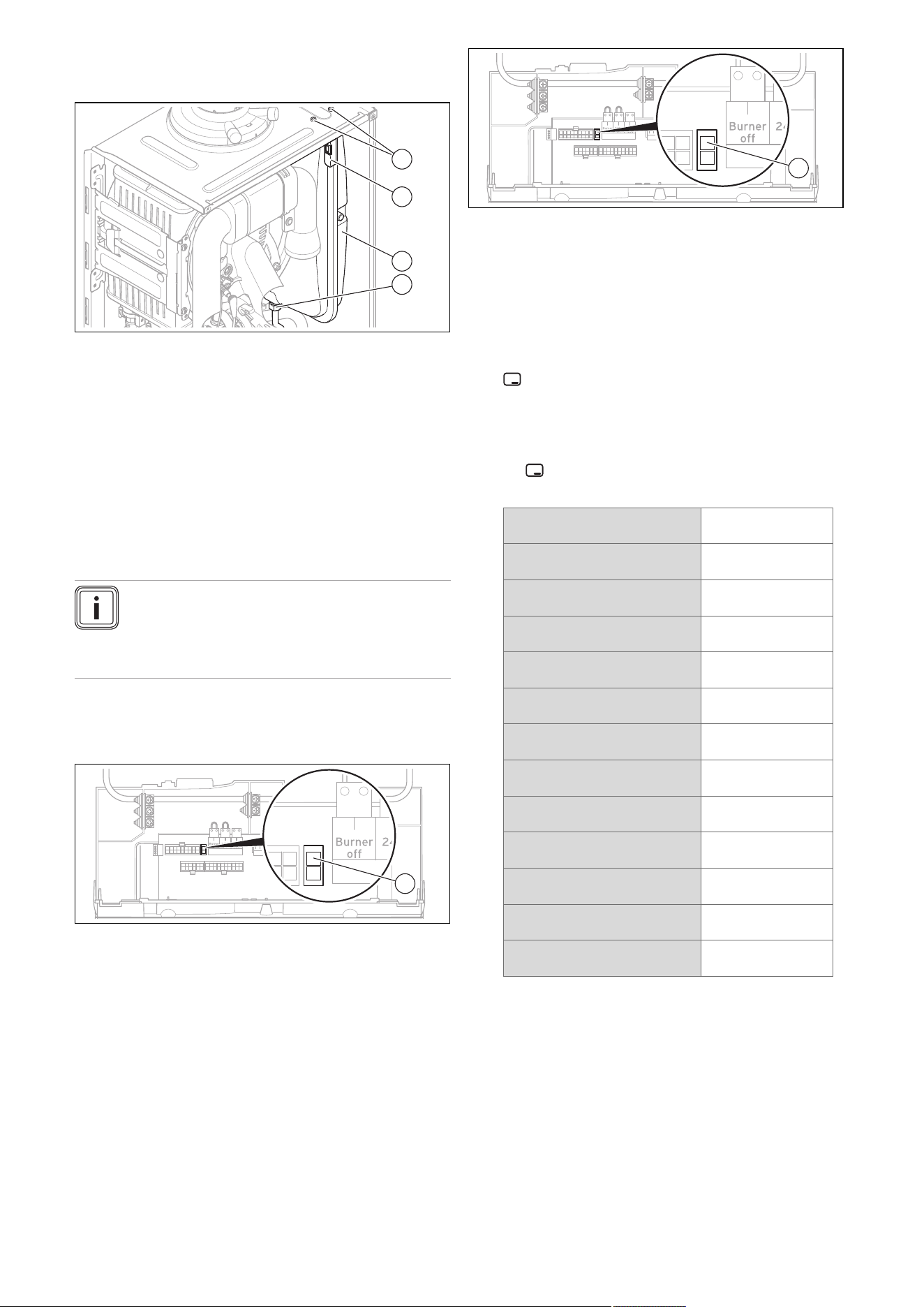
0020244997_07 Installation and maintenance instructions 49
13.6.6 Replacing the expansion vessel
1. Drain the product. (→ Page 44)
1
2
3
4
2. Undo the screwed connection (4).
3. Remove both screws
(1) on the support plate (2).
4. Remove the support plate (2).
5. Pull out the expansion vessel (3) towards the front.
6. Insert the new expansion vessel into the product.
7. Screw the new expansion vessel to the water connec-
tion. Use a new seal for this.
8. Attach the support plate using both screws (1).
9. Fill and purge the product and, if necessary, the heat-
ing installation. (→ Page 35)
13.6.7 Replacing the PCB or the display
Note
If you only replace one component, when the
product is switched on, the new component ad-
opts the parameters that were previously set from
the component that was not replaced.
1. Open the electronics box. (→ Page 28)
2. Replace the PCB or display according to the set-up
and installation instructions supplied.
X31
X12
1
3. If you are replacing the PCB, remove the coding res-
istor (1) (plug X24) from the old PCB and plug the plug
onto the new PCB.
4. Close the electronics box.
13.6.8 Replacing the PCB and the display
1. Open the electronics box. (→ Page 28)
2. Replace the PCB and display according to the set-up
and installation instructions supplied.
X31
X12
1
3. Remove the coding resistor (1) (plug X24) from the old
PCB and plug the plug into the new PCB.
4. Close the electronics box.
5. Press the product's on/off button. (→ Page 32)
◁ After switching on, the product switches directly to
the menu to select the language. The factory-set
language setting is English.
6. Select the required language and confirm by pressing
.
◁ You are automatically taken to D.093 to set the
device specific number.
7. Set the correct value for the relevant product type in
accordance with the table below and confirm by press-
ing .
Product type number
VU 126/5-5 (H-GB) ecoTEC
plus 612
1
VU 156/5-5 (H-GB) ecoTEC
plus 615
3
VU 186/5-5 (H-GB) ecoTEC
plus 618
4
VU 186/5-5 (P-GB) ecoTEC
plus 618
4
VU 246/5-5 (H-GB) ecoTEC
plus 624
9
VU 306/5-5 (H-GB) ecoTEC
plus 630
14
VU 306/5-5 (P-GB) ecoTEC
plus 630
14
VU 386/5-5 (H-GB) ecoTEC
plus 637
20
VUW 196/5-5 (H-GB) ecoTEC
plus 825
6
VUW 246/5-5 (H-GB) ecoTEC
plus 832
10
VUW 246/5-5 (P-GB) ecoTEC
plus 832
10
VUW 306/5-5 (H-GB) ecoTEC
plus 835
13
VUW 286/5-5 (H-GB) ecoTEC
plus 838
17
◁ The electronics are now set to the product type and
the parameters of all diagnostics codes are set to
factory settings.
◁ The installation assistant starts.
8. Make the system-specific settings.

50 Installation and maintenance instructions 0020244997_07
13.7 Completing repair work
1. Establish the power supply.
2. Switch the product back on if this has not yet been
done. (→ Page 32)
3. Install the front casing.
4. Open all service valves and the gas stopcock.
13.8 Checking the product for leak-tightness
▶ Check that the product is leak-tight. (→ Page 38)
14 Decommissioning
14.1 Temporarily decommissioning the product
▶ Press the on/off button.
◁ The display goes out.
▶ Close the gas stopcock.
▶ For products with domestic hot water generation and
products with a connected domestic hot water cylinder,
you must also close the cold-water isolation valve.
14.2 Permanently decommissioning the product
▶ Press the on/off button.
◁ The display goes out.
▶ Disconnect the product from the power grid.
▶ Close the gas stopcock.
▶ Close the cold-water isolation valve.
▶ Drain the product. (→ Page 44)
15 Recycling and disposal
Disposing of the packaging
▶ Dispose of the packaging correctly.
▶ Observe all relevant regulations.
▶ For detailed information refer to www.vaillant.co.uk.

0020244997_07 Installation and maintenance instructions 51
Appendix
A Inspection and maintenance work
The table below lists the manufacturer requirements with respect to minimum inspection and maintenance intervals. If na-
tional regulations and directives require shorter inspection and maintenance intervals, you should observe these instead of
the intervals listed. Each time inspection and maintenance work is carried out, carry out the required preparatory and com-
pletion work.
# Maintenance work Interval
1 Record all of the analysis results in the Benchmark Checklist in these
instructions
Annually
2 Ask the end user whether any significant problems occur when operating
the product
Annually
3 Use the diagnostics system to check the product's fault history Annually
4 Visually inspect whether the air/flue pipe and its opening have been in-
stalled correctly in accordance with the set-up instructions
Annually
5 Check that the unit has been installed correctly and the connections have
been secured
Annually
6 Check that the condensate pipe is in good condition, that it is leak-tight
and that the drain is correct
Annually
7 Check whether all of the externally routed condensate pipes are dimen-
sioned correctly and have been insulated sufficiently (frost protection)
Annually
8 Check whether the gas flow rate corresponds with the specifications on
the data plate and lies within the tolerances specified in these instructions
Annually
9 If the gas flow rate lies outside of the tolerances specified in these in-
structions, eliminate the fault in accordance with the regulations and the
current technology
Annually
10 Check the general condition of the product and, if required, eliminate any
faults that are found
Annually
11 Carry out the combustion analysis: Measure the CO content, CO₂ content
and the CO/CO₂ ratio. For products with a rear air/flue connection: The
combustion analysis can only be carried out when the unit casing has
been removed; it is not necessary to test these products for flue gas recir-
culation
Annually
12 Check the product's recirculation at the supply air test point on the air/flue
pipe. If required, inspect the entire air/flue system and, if necessary, cor-
rect the fault
Annually
13 Disconnect the product from the electrical installation Annually
14 Check and, if required, correct the electrical installation Annually
15 Removing dirt from the product and the vacuum chamber Annually
16 Visually check the heat cell to ascertain its condition and detect any cor-
rosion, rust or damage, and carry out maintenance work, if required
Annually
17 Check that the gas stopcock and service valves function correctly Annually
18 Check the quality of the heating water: Clarity (clouding), correct inhibitor
and pH value
Annually
19 Removing the compact thermal module at regular intervals
42
20 Check the burner for damage at regular intervals
21 Checking the insulating mats in the combustion area and replacing dam-
aged insulating mats
at regular intervals
22 Cleaning the heat exchanger at regular intervals
43
23 Cleaning the condensate trap Annually
44
24 Filling the condensate trap Annually
34
25 Installing the compact thermal module at regular intervals
44
26 Checking the pre-charge pressure of the expansion vessel at regular intervals
27 Cleaning the strainer in the cold water inlet at regular intervals
44
28 Check the impeller sensor for dirt/damage at regular intervals
29 If the water volume is insufficient (domestic hot water) or the outlet tem-
perature is insufficient, check the secondary heat exchanger
at regular intervals
30 Reassemble the product After each time maintenance
work is carried out
31 Opening the service valves Annually
52 Installation and maintenance instructions 0020244997_07
# Maintenance work Interval
32 Filling the heating installation at regular intervals
35
33 Completing inspection and maintenance work Annually
45
34 Perform the gas family check at regular intervals
35 Visually check the ignition and burner behaviour Annually
36 Checking the CO/CO₂ content following maintenance work Annually
37 Check the product for gas, flue gas, water and condensate leaks Annually
B Installer level – Overview
Setting level Values
Unit Increment, select, explanation
Factory
setting
Min. Max.
Installer level →
Enter code 00 99 – 1 (competent person code 17) –
Installer level → Fault list →
F.XX – F.XX¹ Current value
– –
–
Installer level → Test programs →
Gas family check Current value – LPG, natural gas –
Installer level → Test programs → Check programs →
P.00 Purging – – – Yes, No –
P.01 Maximum load – – – Yes, No –
P.02 Minimum load – – – Yes, No –
P.06 Filling mode – – – Yes, No –
Installer level → Test programs → Function menu →
T.01 Internal pump – – – On, Off –
T.02 3-way valve – – – On, Off –
T.03 Fan – – – On, Off –
T.04 Cylinder charging pump – – – On, Off –
T.05 Circulation pump – – – On, Off –
T.06 External pump – – – On, Off –
T.08 Burner – – – On, Off –
Installer level → Test programs → Electronics self-test →
Self-test – – – Yes, No –
Installer level → Appliance config. →
Language – – – Languages available for selection Country-
specific
Target flow temp. 30 75 ℃ 1 –
DHW temperature 30 60 ℃ 1
Product with domestic hot water generation or
connected domestic hot water cylinder
–
Comfort mode
– –
– On, Off Off
¹Fault lists are only displayed, and can only be deleted, if faults have occurred.
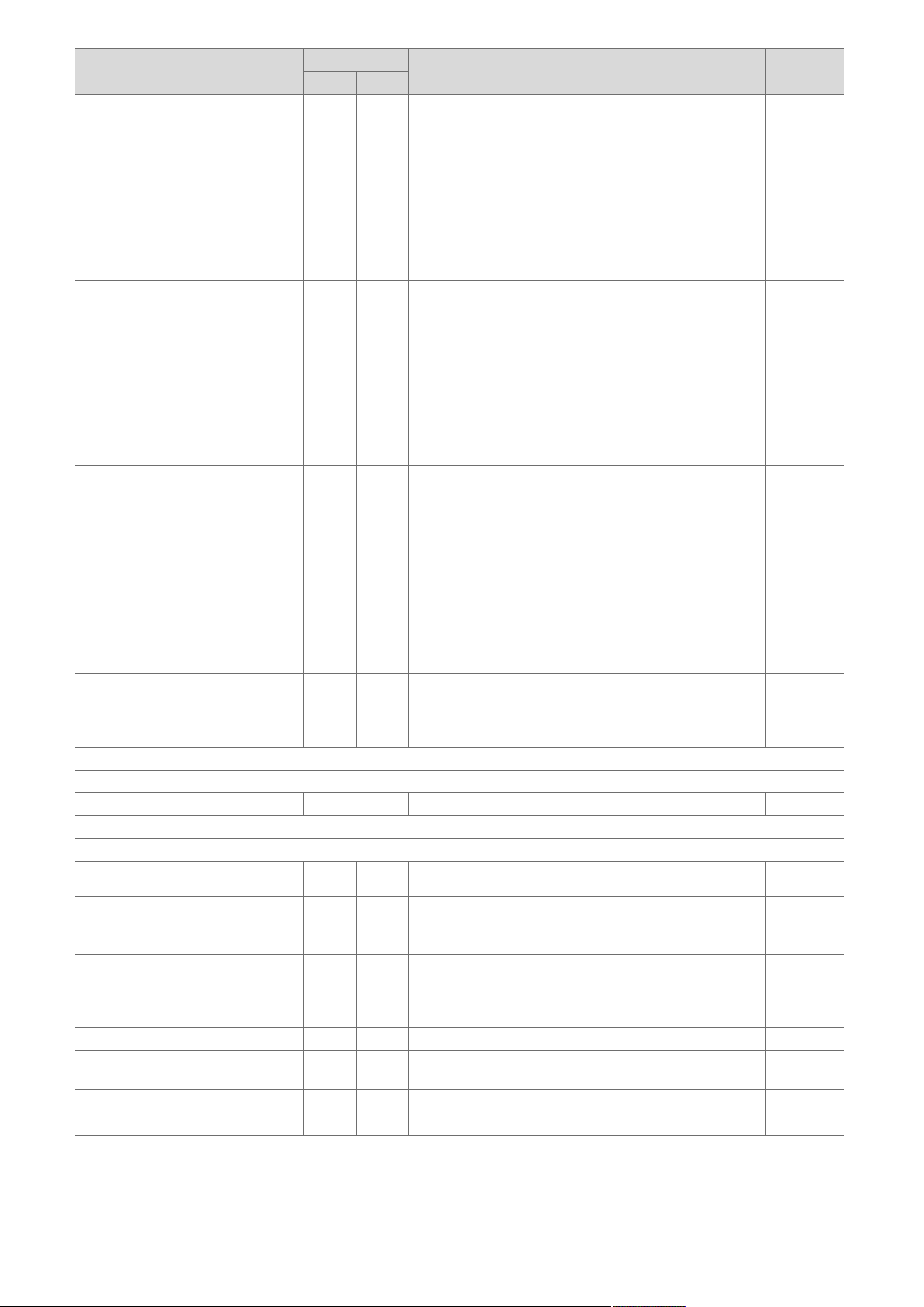
0020244997_07 Installation and maintenance instructions 53
Setting level Values
Unit Increment, select, explanation
Factory
setting
Min. Max.
Auxiliary relay 1 10 – 1 = Circulation pump
2 = External pump
3 = Cylinder charging pump
4 = Extraction hood
5 = External solenoid valve
6 = External fault message
7 = Solar pump (not active)
8 = eBUS remote control (not active)
9 = Anti-legionella pump (not active)
10 = Solar valve (not active)
2
Accessory relay 1 1 10 – 1 = Circulation pump
2 = External pump
3 = Cylinder charging pump
4 = Extraction hood
5 = External solenoid valve
6 = External fault message
7 = Solar pump (not active)
8 = eBUS remote control (not active)
9 = Anti-legionella pump (not active)
10 = Solar valve (not active)
2
Accessory relay 2 1 10 – 1 = Circulation pump
2 = External pump
3 = Cylinder charging pump
4 = Extraction hood
5 = External solenoid valve
6 = External fault message
7 = Solar pump (not active)
8 = eBUS remote control (not active)
9 = Anti-legionella pump (not active)
10 = Solar valve (not active)
2
Heating partial load – – kW Partial load only, full load only, auto Auto
Contact details Phone
num-
ber
– – 0 – 9 –
Factory setting – – – On, Off –
Installer level → Diagnostics menu →
D.XXX – D.XXX Current value
– –
–
Installer level → Start inst. assistant →
Language – – – Languages available for selection Country-
specific
Filling mode: 3-way valve is in mid-
position
0 2 – 0 = Normal operating mode
1 = Mid-position (parallel operation)
2 = Permanent heating position
–
Purge program: Select circ. using
+/-
– – – Automatic adaptive purging of the heating circuit
and domestic hot water circuit
Not active
Active
–
Target flow temp. 30 75 ℃ 1 –
DHW temperature 35 60 ℃ 1
Product with domestic hot water generation
–
Comfort mode
– –
– On, Off –
Heating partial load – – kW Partial load only, full load only, auto Auto
¹Fault lists are only displayed, and can only be deleted, if faults have occurred.
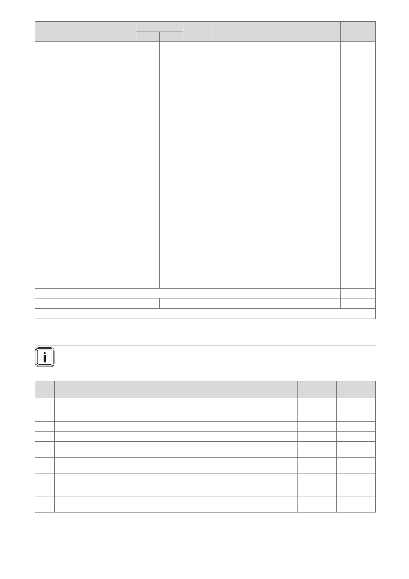
54 Installation and maintenance instructions 0020244997_07
Setting level Values
Unit Increment, select, explanation
Factory
setting
Min. Max.
Auxiliary relay 1 10 – 1 = Circulation pump
2 = External pump
3 = Cylinder charging pump
4 = Extraction hood
5 = External solenoid valve
6 = External fault message
7 = Solar pump (not active)
8 = eBUS remote control (not active)
9 = Anti-legionella pump (not active)
10 = Solar valve (not active)
2
Accessory relay 1 1 10 – 1 = Circulation pump
2 = External pump
3 = Cylinder charging pump
4 = Extraction hood
5 = External solenoid valve
6 = External fault message
7 = Solar pump (not active)
8 = eBUS remote control (not active)
9 = Anti-legionella pump (not active)
10 = Solar valve (not active)
2
Accessory relay 2 1 10 – 1 = Circulation pump
2 = External pump
3 = Cylinder charging pump
4 = Extraction hood
5 = External solenoid valve
6 = External fault message
7 = Solar pump (not active)
8 = eBUS remote control (not active)
9 = Anti-legionella pump (not active)
10 = Solar valve (not active)
2
Contact details Phone number – 0-9 –
End the installation assistant? – – – Yes, No –
¹Fault lists are only displayed, and can only be deleted, if faults have occurred.
C Overview of diagnostics codes
Note
Since the code table is used for various products, some codes may not be visible for the product in question.
Code Parameter Values or explanations
Factory
setting
Own setting
D.000 Heating partial load Adjustable partial heat load in kW
Auto: Product automatically adjusts max. partial load to
current system demand
Auto
D.001 Pump overrun: Heating 1 to 60 min 5 min
D.002 Max. anti-cycl. time: Heating 2 to 60 min 20 min
D.003 Outlet temperature actual value In °C Not ad-
justable
D.004 Cylinder temperature actual value In °C Not ad-
justable
D.005 Heating target flow temperature In °C; the maximum value that is set in D.071 and is
restricted by means of an eBUS control if such a control
is connected
Not ad-
justable
D.006 Outlet temperature target value 35 to 65 ℃ Not ad-
justable

0020244997_07 Installation and maintenance instructions 55
Code Parameter Values or explanations
Factory
setting
Own setting
D.007 Comfort mode target value
APC target value
Cylinder temperature target value
Product with integrated domestic hot water generation,
and product with integrated domestic hot water genera-
tion and shift-load cylinder
35 to 65 ℃
Product with heating mode only
Frost protection is at 15 °C, then 40 to 70 °C (max.
temperature can be adjusted under D.020)
Not ad-
justable
D.008 Controller 3-4 Room thermostat open (no heat requirement)
Room thermostat closed (heat requirement)
Not ad-
justable
D.009 eBUS controller target value In °C Not ad-
justable
D.010 Internal pump On, Off Not ad-
justable
D.011 External pump On, Off Not ad-
justable
D.012 Cyl. charging pump On, Off Not ad-
justable
D.013 Circulation pump On, Off Not ad-
justable
D.014 Pump speed target value Target value of internal high-efficiency pump in %. Pos-
sible settings:
0 = Auto
1 = 53
2 = 60
3 = 70
4 = 85
5 = 100
0 = Auto
D.015 Pump speed actual value Actual value for internal high-efficiency pump in % Not ad-
justable
D.016 Controller 24 V DC: Heating mode Heating mode off/on Not ad-
justable
D.017 Control type Control type:
0 = Flow, 1 = Return
Return: Automatic detection function for heat output
inactive. Max. possible partial heat load when D.000
is on Auto.
0 = Flow
D.018 Pump operating mode 1 = Comfort (continuously operating pump)
Internal pump is switched on when the heating flow tem-
perature is not at Heating off and the heat requirement
is enabled via an external control
3 = Eco (intermittently operating pump)
Internal pump is switched on every 25 minutes for 5
minutes once the overrun time has elapsed
3 = Eco
D.019 Pump operating mode: 2-stage
pump
Setting for two-stage pump operating mode
0: Burner mode stage 2, pump prerun/overrun stage 1
1: Heating mode and pump prerun/overrun stage 1,
domestic hot water mode stage 2
2: Automatic heating mode, pump prerun/overrun
stage 1, domestic hot water mode stage 2
3: Always stage 2
4: Automatic heating mode, pump prerun/overrun
stage 1, domestic hot water mode stage 1
2
D.020 Max. DHW temperature target
value
Adjustment range: 50–70 °C (actoSTOR 65 °C) 65 °C
D.022 DHW demand On, Off Not ad-
justable
D.023 Heating mode status Heating on, heating off (summer mode) Not ad-
justable
D.025 Ext. eBUS signal: Cylinder char-
ging
On, Off Not ad-
justable

56 Installation and maintenance instructions 0020244997_07
Code Parameter Values or explanations
Factory
setting
Own setting
D.026 Auxiliary relay 1 = Circulation pump
2 = External pump
3 = Cylinder charging pump
4 = Extraction hood
5 = External solenoid valve
6 = External fault message
7 = Solar pump (not active)
8 = eBUS remote control (not active)
9 = Anti-legionella pump (not active)
10 = Solar valve (not active)
2 = External
pump
D.027 Accessory relay 1 Switching of relay 1 on the VR 40 "2 in 7" multi-func-
tional module
1 = Circulation pump
2 = External pump
3 = Cylinder charging pump
4 = Extraction hood
5 = External solenoid valve
6 = External fault message
7 = Solar pump (not active)
8 = eBUS remote control (not active)
9 = Anti-legionella pump (not active)
10 = Solar valve (not active)
2 = External
pump
D.028 Accessory relay 2 Switching of relay 2 on the VR 40 "2 in 7" multi-func-
tional module
1 = Circulation pump
2 = External pump
3 = Cylinder charging pump
4 = Extraction hood
5 = External solenoid valve
6 = External fault message
7 = Solar pump (not active)
8 = eBUS remote control (not active)
9 = Anti-legionella pump (not active)
10 = Solar valve (not active)
2 = External
pump
D.029 Water circulation vol. actual value Actual value in m³/h Not ad-
justable
D.033 Fan speed target value In rpm Not ad-
justable
D.034 Fan speed actual value In rpm Not ad-
justable
D.035 3-way valve position Heating mode
Parallel operation (mid-position)
DHW mode
Not ad-
justable
D.036 DHW flow rate In l/min Not ad-
justable
D.039 Solar inlet temp. actual value Actual value in °C Not ad-
justable
D.040 Flow temperature actual value Actual value in °C Not ad-
justable
D.041 Return temperature actual value Actual value in °C Not ad-
justable
D.044 Ionisation value actual value Display field 0 to 1020
> 800 no flame
< 400 good flame
Not ad-
justable
D.046 Pump mode 0 = Relay with disable facility
1 = PWM with disable facility
0 = Relay
with disable
facility
D.047 Current outside temperature (with Vaillant weather-compensated control)
Actual value in °C
Not ad-
justable

0020244997_07 Installation and maintenance instructions 57
Code Parameter Values or explanations
Factory
setting
Own setting
D.050 Offset min. speed In rpm, adjustment range: 0 to 3000 Nominal
value set in
factory
D.051 Offset max. speed In rpm, adjustment range: -990 to 0 Nominal
value set in
factory
D.058 Solar post-heating 0 = Solar post-heating deactivated
3 = DHW activation target value minimum 60 °C, thermo-
static mixing valve required between product and draw-
off point
0 = Solar
post-heating
deactivated
D.060 Number of safety therm. shut-
downs
Number of shutdowns Not ad-
justable
D.061 No. of shut-downs in ign. flame
controller
Number of unsuccessful ignitions in the last attempt Not ad-
justable
D.064 Avg. ignition time In seconds Not ad-
justable
D.065 Max. ignition time In seconds Not ad-
justable
D.067 Remaining anti-cycl. time for heat-
ing
In minutes Not ad-
justable
D.068 Number of first start attempts Number of unsuccessful ignitions Not ad-
justable
D.069 Number of second start attempts Number of unsuccessful ignitions Not ad-
justable
D.070 3-way valve operation 0 = Normal operating mode
1 = Parallel operation (mid-position)
2 = Permanent heating position
0 = Normal
operating
mode
D.071 Max. heating target flow temp. 40 to 80 ℃ 75 ℃
D.072 Pump overrun after cylinder char-
ging
Adjustable from 0–10 minutes in increments of 1 minute 2 mins
D.073 Offset setting for comfort mode Adjustable from -15 K to 5 K 0
D.074 Anti-legionella funct. with integ-
rated cyl.
0 = Off
1 = On
1 = On
D.075 Max. cylinder charging time 20–90 min 45 mins
D.076 Device Specific Number Device specific number = DSN
1 = VU 126/5-5 (H-GB) ecoTEC plus 612
3 = VU 156/5-5 (H-GB) ecoTEC plus 615
4 = VU 186/5-5 (H-GB) ecoTEC plus 618, VU 186/5-5
(P-GB) ecoTEC plus 618
9 = VU 246/5-5 (H-GB) ecoTEC plus 624
14 = VU 306/5-5 (H-GB) ecoTEC plus 630, VU 306/5-5
(P-GB) ecoTEC plus 630
20 = VU 386/5-5 (H-GB) ecoTEC plus 637
6 = VUW 196/5-5 (H-GB) ecoTEC plus 825
10 = VUW 246/5-5 (H-GB) ecoTEC plus 832, VUW
246/5-5 (P-GB) ecoTEC plus 832
62 = VUW 306/5-5 (H-GB) ecoTEC plus 835
17 = VUW 286/5-5 (H-GB) ecoTEC plus 838, VUI 286/5-
5 (H-GB) ecoTEC plus 938
Not ad-
justable
D.077 DHW partial load Adjustable cylinder charging output in kW
D.078 DHW max. flow temperature Limit on cylinder charging temperature in °C
50 °C – 80 °C
Note
The chosen value must be at least 15 K or 15 °C above
the target cylinder value.
75 °C
D.080 Heating operating hours In hours (h) Not ad-
justable
D.081 DHW operating hours In hours (h) Not ad-
justable
D.082 Heating burner starts Number of burner start-ups Not ad-
justable

58 Installation and maintenance instructions 0020244997_07
Code Parameter Values or explanations
Factory
setting
Own setting
D.083 DHW burner starts Number of burner start-ups Not ad-
justable
D.084 Maintenance in Adjustment range: 0 to 3000 hrs and "---" for deactivated „---”
D.088 Min. DHW flow rate Switch-on delay for domestic hot water draw-off detec-
tion via impeller (only products with integrated domestic
hot water generation)
0 = 1.5 l/min and no delay,
1 = 3.7 l/min and 2 sec. delay
1.5 l/min and
no delay
D.090 eBUS controller Status of digital control
Recognised, not recognised
Not ad-
justable
D.091 Status DCF77 Status of DCF with outdoor temperature sensor connec-
ted
No reception
Reception
Synchronised
Valid
Not ad-
justable
D.092 actoSTOR communication status actoSTOR module detection
0 = Not connected
1 = Connection fault: No communication via PeBus,
actoSTOR module was previously detected
2 = Connection active
Not ad-
justable
D.093 Adjust Device Specific Number Device Specific Number (DSN)
Adjustment range: 0 to 99
D.094 Clear fault history Delete fault list
0 = No
1 = Yes
D.095 Software version: PeBUS parti-
cipant
PCB (BMU)
Display (AI)
actoSTOR (APC)
HBI/VR34
Not ad-
justable
D.096 Reset to factory settings? Reset all adjustable parameters to factory setting
0 = No
1 = Yes
D.098 Coding resistor Display xx.yy
xx = Coding resistor 1 in cable harness for output range:
8 = VU 126/5-5 (H-GB) ecoTEC plus 612; VU 156/5-5
(H-GB) ecoTEC plus 615; VU 186/5-5 (H-GB) ecoTEC
plus 618, VU 186/5-5 (P-GB) ecoTEC plus 618; VUW
196/5-5 (H-GB) ecoTEC plus 825
9 = VU 246/5-5 (H-GB) ecoTEC plus 624; VUW 246/5-5
(H-GB) ecoTEC plus 832; VUW 246/5-5 (P-GB) ecoTEC
plus 832
10 = VU 306/5-5 (H-GB) ecoTEC plus 630; VU 306/5-5
(P-GB) ecoTEC plus 630; VUW 306/5-5 (H-GB) ecoTEC
plus 835
11 = VU 386/5-5 (H-GB) ecoTEC plus 637; VUW 286/5-
5 (H-GB) ecoTEC plus 838; VUI 286/5-5 (H-GB) ecoTEC
plus 938
yy = Coding resistor 2 on PCB for gas group:
02 = P gas
03 = H gas
07 = L gas
Not ad-
justable

0020244997_07 Installation and maintenance instructions 59
D Status codes – Overview
Note
Since the code table is used for various products, some codes may not be visible for the product in question.
Code Meaning
S.00 Heating: No heat de-
mand
Heating has no heat demand. The burner is off.
S.01 Heating mode: Fan start-
up
The fan start-up for heating mode is activated.
S.02 Heating mode: Pump
pre-run
The pump prerun for heating mode is activated.
S.03 Heating mode: Ignition The ignition for heating mode is activated.
S.04 Heating mode: Burner
on
The burner for heating mode is activated.
S.05 Heating mode: Pump/fan
overrun
The pump/fan overrun for heating mode is activated.
S.06 Heating mode: Fan over-
run
The fan overrun for heating mode is activated.
S.07 Heating mode: Pump
overrun
The pump overrun for heating mode is activated.
S.08 Heating mode: Anti-cyc-
ling time
The anti-cycling time for heating mode is activated.
S.10 DHW demand The domestic hot water demand is activated.
S.11 DHW mode: Fan start-up The fan start-up for domestic hot water mode is activated.
S.13 DHW mode: Ignition The ignition for domestic hot water mode is activated.
S.14 DHW mode: Burner on The burner for domestic hot water mode is activated.
S.15 DHW mode: Pump/fan
overrun
The pump/fan overrun for domestic hot water mode is activated.
S.16 DHW mode: Fan overrun The fan overrun for domestic hot water mode is activated.
S.17 DHW mode: Pump over-
run
The pump overrun for domestic hot water mode is activated.
S.20 DHW demand The domestic hot water demand is activated.
S.21 DHW mode: Fan start-up The fan start-up for domestic hot water mode is activated.
S.22 DHW mode: Pump pre-
run
The pump prerun for domestic hot water mode is activated.
S.23 DHW mode: Ignition The ignition for domestic hot water mode is activated.
S.24 DHW mode: Burner on The burner for domestic hot water mode is activated.
S.25 DHW mode: Pump/fan
overrun
The pump/fan overrun for domestic hot water mode is activated.
S.26 DHW mode: Fan overrun The fan overrun for domestic hot water mode is activated.
S.27 DHW mode: Pump over-
run
The pump overrun for domestic hot water mode is activated.
S.28 DHW anti-cycling time The anti-cycling time for domestic hot water mode is activated.
S.30 No heat demand: Con-
troller
Room thermostat blocks heating mode.
S.31 No heat demand: Sum-
mer mode
Summer mode is activated; there is no heat demand.
S.32 Waiting time deviation:
Fan speed
The waiting period for the fan start-up is activated.
S.34 Heating mode: Frost pro-
tection
The frost protection function for heating mode is activated.
S.39 Contact thermostat
triggered
The surface-mounted thermostat or the condensate pump has triggered.
S.40 Comfort protection act-
ive
The comfort protection mode is activated.
S.41 Water pressure too high The system pressure is too high.
S.42 Flue non-return flap
closed
Flue non-return flap return signal blocks burner operation (only in conjunction with the multi-functional
module) or condensate pump defective, heat demand is blocked.
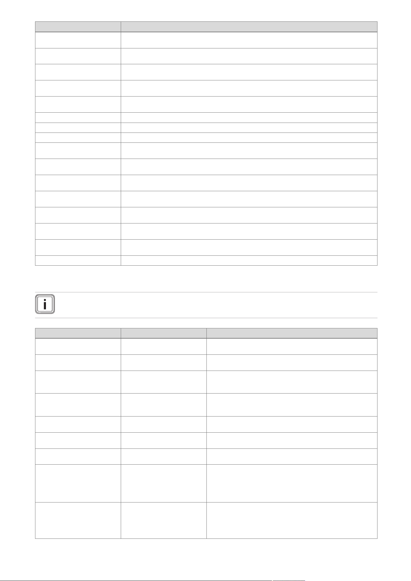
60 Installation and maintenance instructions 0020244997_07
Code Meaning
S.46 Comfort protection: Min-
imum load, loss of flame
Comfort protection mode for flame loss at minimum load is activated.
S.53 Waiting time: Water
shortage
The product is within the waiting period of the modulation block/operating block function as a result of
a water deficiency (flow/return spread too large).
S.54 Waiting time: Water
shortage
Product is in the waiting period of the operation blocking function as a result of low water pressure
(temperature gradient).
S.57 Waiting time: Measuring
program
The product is within the waiting period as a result of the measuring programme.
S.58 Burner modulation limit-
ation
The burner modulation limitation is activated.
S.61 Fault: Incorrect gas type The coding resistor on the PCB does not match the entered gas group (see also F.92).
S.62 Adjust CO2 Set the CO
2
content.
S.63 Fault: Check gas route A fault message is activated. Check the gas route.
S.76 Service message: Check
water pressure
A service message is activated. Check the water pressure.
S.88 Purging programme is
running
The purge programme is activated.
S.92 Water circulation volume
self-test
The self-test for the water circulation volume is activated.
S.93 Flue gas measurement
not possible
Flue gas analysis is not currently possible.
S.96 Self-test: Return temper-
ature sensor
The self-test for the return temperature sensor is activated.
S.97 Water pressure sensor
self-test
The self-test for the water pressure sensor is activated.
S.98 Self-test: Flow/return
temperature sensor
The self-test for the flow/return temperature sensor is activated.
S.99 Vaillant self-test The Vaillant self-test is activated.
E Overview of fault codes
Note
Since the code table is used for various products, some codes may not be visible for the product in question.
Code/meaning Possible cause Measure
F.00 Flow temperature sensor
interruption
Flow temperature sensor de-
fective or not connected
▶ Check: Flow temperature sensor, plug, cable harness, PCB.
F.01 Return temperature sensor
interruption
Return temperature sensor de-
fective or not connected
▶ Check: Return temperature sensor, plug, cable harness, PCB.
F.02 Interruption: DHW outlet
sensor
Shift-load cylinder temperature
sensor defective or not connec-
ted
▶ On the shift-load cylinder, check (only in conjunction with
F.91): Plug, cable harness, temperature sensor.
F.03 Cylinder temperature
sensor interruption
Shift-load cylinder temperature
sensor defective or not connec-
ted
▶ On the shift-load cylinder, check (only in conjunction with
F.91): Temperature sensor plug, PCB plug, cable harness.
F.10 Flow temperature sensor
short circuit
Flow temperature sensor de-
fective or has short-circuited
▶ Check: NTC plug, cable harness, cable/housing, PCB, NTC
sensor.
F.11 Return temperature sensor
short circuit
Return temperature sensor de-
fective or has short-circuited
▶ Check: NTC plug, cable harness, housing, PCB, NTC sensor.
F.12 DHW outlet sensor short
circuit
Cylinder charging sensor de-
fective or has short-circuited
▶ Check (only in conjunction with F.91): NTC plug, cable har-
ness, NTC sensor, PCB.
F.13 Cylinder temperature
sensor short circuit
Warm-start sensor/cylinder tem-
perature sensor defective or not
connected
1. Check: NTC plug, earth connection, cable harness, NTC
sensor, PCB.
2. Check the following on the shift-load cylinder (in conjunction
with F.91): NTC plug, earth connection, cable harness, NTC
sensor, connection to the PCB.
F.20 Safety switch-off: Temper-
ature limiter
Maximum temperature at the
flow/return temperature sensor
is too high when the safety cut-
out function is operating using
the NTC
▶ Check: Flow temperature sensor (correct thermal connection),
cable harness, sufficient purging.

0020244997_07 Installation and maintenance instructions 61
Code/meaning Possible cause Measure
F.22 Safety switch-off: Low wa-
ter pressure
No/insufficient water in the
product or the water pressure is
too low
1. Check: Plug, cable to heating pump or water pressure
sensor, water pressure sensor, heating pump.
2. Activate and purge check programme P.0.
F.23 Safety switch-off:
Temp.spread too large
Temperature spread too great.
Water circulation too low
▶ Check: Plug, cable to heating pump/water pressure sensor,
air/insufficient water in the heating circuit, flow and return tem-
perature sensor inverted, strainer in the hydraulic block, water
pressure sensor, heating pump (sufficient circulation, stage 2:
D.19, D.14, non-return valve). Activate check programme P.0.
F.24 Safety switch-off: Temp.
incr. too fast
Temperature increase too fast ▶ Check: Plug, cable to the heating pump, air/insufficient water
in the heating circuit, internal air vent (function), heating pump
(system pressure too low, temperature gradient too great on
heating flow, non-return valve). Activate check programme P.0.
F.25 Safety switch-off: Flue
temp. too high
flue gas temperature too high ▶ Check: Plug, safety cut-out plug, cable harness, cable to the
heating pump, internal air vent (function), flue gas route (block-
age, adverse wind conditions, flue pipework too long), insuf-
ficient water in heating circuit, heating pump, activate check
programme P.0.
F.26 Fault: Fuel valve not work-
ing
Gas valve assembly stepper
motor defective or not connec-
ted
▶ Check: Gas valve assembly stepper motor (plug, cable, pas-
sage for rinsing, voltage), multiple plug, cable harness.
F.27 Safety switch-off: Flame
simulation
Monitoring electrode reports an
incorrect flame
▶ Check: Gas pressure at upper test opening, monitoring elec-
trode, PCB, gas solenoid valve.
F.28 Start-up failure: Ignit. un-
successful
Failure during start-up or igni-
tion unsuccessful. Gas pressure
monitor or thermal cut-out has
been triggered.
▶ Check: Gas stopcock, gas flow pressure, gas valve assembly,
air intake pipe (blockage, loosened screw), condensate route
(blockage), multiple plug, cable harness, ignition transformer,
ignition cable, ignition plug, ignition electrode, monitoring elec-
trode, electronics, earthing, CO₂ setting.
F.29 Operating failure: Ignit.
unsuccessful
Gas supply interrupted intermit-
tently. Re-ignition failed.
▶ Check: Flue gas recirculation, condensate route (blockage),
earthing, cable to the gas valve assembly and electrode (loose
connection).
F.32 Fault: Fan Fan defective or not connected ▶ Check: Plug, cable harness, fan (blockage, function, correct
speed), Hall sensor, PCB, flue gas route (blockage).
F.42 Fault: Coding resistor Coding resistor or gas group
resistor causes a short circuit
▶ Check: Plug, earth connection, cable, output coding resistor (in
the cable harness).
F.49 Fault: eBUS Undervoltage on the eBUS ▶ Check: eBUS (overload, two power supplies with different po-
larities, short circuit).
F.52 Mass flow sensor not con-
nected
Mass flow sensor defective or
not connected
▶ Check: Plug, cable harness, mass flow sensor.
F.53 Gas valve assembly mass
flow unexpected
The mass flow through the gas
valve assembly is not as expec-
ted.
▶ Check: Gas flow pressure too low, sharp drop in pressure
during ignition or full load, filter below Venturi filter cap wet
or blocked, internal pressure measuring point in the Venturi
blocked (do not use any lubricants on the O-ring in the Ven-
turi), gas valve assembly does not regulate correctly.
F.54 Fault: Boiler start No gas inlet pressure or insuffi-
cient gas inlet pressure causes
faults when the product is star-
ted
▶ Check (in conjunction with F.28/F.29): Gas stopcock, gas valve
assembly, plug, cable harness.
F.55 Fault: CO sensor All-gas sensor defective or has
short-circuited
▶ Check: Plug, cable harness, all-gas sensor, PCB.
F.56 Safety switch-off: CO limit
exceeded
Safety shutdown after the CO
limit value is exceeded
▶ Check: Gas valve assembly, plug, cable harness. If the fault
occurs again after being cleared, the gas valve assembly is
defective.
F.57 Fault: Measuring program Regulation fault caused by cor-
roded ignition electrode
▶ Check: Ignition electrode, PCB (microcontrol).
F.61 Fault: Fuel valve actuation The gas valve assembly cannot
be actuated
▶ Check: Cable harness, plug, gas valve assembly (rinse), PCB.
F.62 Fault: Fuel valve switch-off
delay
Delayed switch-off sequence for
the gas valve after the flame is
extinguished
▶ Check: Gas valve, surface of the burner (dirt), plug, cable har-
ness, PCB.
F.63 Fault: EEPROM EEPROM faulty ▶ Replace: PCB.
F.64 Fault: Electronics/sensor Electronics, safety-relevant
sensor or cable defective
▶ Check: Flow sensor, cable to the sensor, flame recording
sensor (e.g. ionisation electrode) for an unstable signal,
electronics.
F.65 Fault: Electronics temp. Electronics defective or too hot
due to external influences
1. Check: PCB.
2. If required, reduce the environmental temperature.
F.67 Fault: Electronics/flame Implausible flame signal ▶ Check: Cable harness, flame monitor, PCB.

62 Installation and maintenance instructions 0020244997_07
Code/meaning Possible cause Measure
F.68 Fault: Flame signal un-
stable
Flame monitor reports an un-
stable flame signal
▶ Check: Air ratio, gas flow pressure, condensate route (block-
age), gas injector, ionisation flow (cable, electrode), flue gas
recirculation.
F.70 Fault: Invalid Device Spe-
cific Number
Incorrect/missing Device
Specific Number or
incorrect/missing coding resistor
▶ If the display and PCB have been replaced, change the Device
Specific Number under D.93.
F.71 Fault: Flow temperature
sensor
Flow temperature sensor re-
turns implausible values
▶ Check: Flow temperature sensor (correct thermal connection).
F.72 Fault: Flow/return temper-
ature sensor
Temperature difference
between flow and return
temperature sensor is too great
▶ Check: Flow temperature sensor/return temperature sensor
(function, correct thermal connection).
F.73 Fault: Water press. sensor
(signal too weak)
Water pressure sensor reports
that the water pressure is too
low
▶ Check: Water pressure, earth connection, cable, plug, water
pressure sensor (short circuit to GDN).
F.74 Fault: Water press. sensor
(signal too strong)
Water pressure too high 1. Drain water.
2. Check the water pressure sensor.
F.75 Fault: Pump/ water short-
age
Insufficient pressure jump de-
tected when starting the pump
1. Check: Water pressure sensor, heating pump (blockage),
heating circuit (air, sufficient water volume), adjustable by-
pass, external expansion vessel (must be connected at the
return). Activate check programme P.0.
2. If a low loss header or heating pipes with a diameter greater
than 1 1/2 inch are installed, replace the 3/4-inch seal in
the heating flow with a screen. If required, install the F.75
service set.
F.77 Fault: Flue non-ret.
valve/condens. pump
No flue non-return flap feed-
back; condensate pump over-
flow
▶ Check: Cable to VR40 accessory, flue non-return flap (wiring,
feedback switch), condensate pump, bridge from the surface-
mounted thermostat, 2 in 7 multi-functional module (bridge).
F.78 Interruption: DHW outlet
sensor at ext. control
UK link box is connected
without the domestic hot water
temperature sensor being
bridged
1. Check: Accessory (configuration/electrical connection).
2. The unit displays a fault, but the unit has not malfunctioned.
F.80 Fault: actoSTOR inlet
sensor
Inlet temperature sensor defect-
ive or not connected
▶ Check (only in conjunction with F.91): NTC sensor, plug, cable
harness, PCB.
F.81 Fault: cylinder charging
pump
Cylinder is not fully charged
after specified time
▶ Check (only in conjunction with F.91): Cylinder charging
sensor, cylinder sensor, impeller sensor/limiter, prioritising
diverter valve, pump, actoSTOR pump (air), cable harness,
secondary heat exchanger (blockage).
F.82 Fault: Ext. current anode External current anode defect-
ive or not connected
▶ Check: Cable harness, external current anode. If the external
current anode is not installed: Plug edge connector X43 with a
bridge into the PCB.
F.83 Fault: NTC temp. gradient Temperature difference
between flow and return
temperature sensor is too small
▶ Check: Flow/return temperature sensor (function, correct
thermal connection), sufficient water volume.
F.84 Fault: NTC temp. diff. im-
plausible
Temperature difference is im-
plausible
▶ Check: Flow/return temperature sensor (correct thermal con-
nection, sensors are inverted).
F.85 Fault: NTCs fitted incor-
rectly
Flow/return temperat-
ure sensors returning
incorrect/implausible values
▶
Check: Flow/return temperature sensor (correct thermal con-
nection).
F.90 Fault: Communication Communication with actoSTOR
interrupted
1. Check: Plug, check cable harness to the actoSTOR module
(PEBus).
2. If the product is to be operated without an actoSTOR:
Set D.092=0, if required, plug edge connector X31 into
the BMU, if required plug edge connector X1 into the
actoSTOR.
F.91 Fault: actoSTOR sensor Sensor on the actoSTOR is
defective
▶ Check: Plug, cable harness, sensor.
F.92 Fault: Incorrect gas type The coding resistor on the PCB
does not match the gas group
that is entered
1. Check: Coding resistor.
2. Carry out the gas family check again and enter the correct
gas group.
F.93 Fault: Check gas route Combustion quality outside the
permitted range
▶ Check: Gas injector (suitable for the gas group), flue gas re-
circulation, gas group, internal pressure measuring point in the
Venturi (blockage). Do not use any lubricants on the O-ring in
the Venturi.
F.94 Fault: Vortex and differen-
tial pressure
Sensors return implausible val-
ues.
▶ Check: Cable harness, plug, sensors.
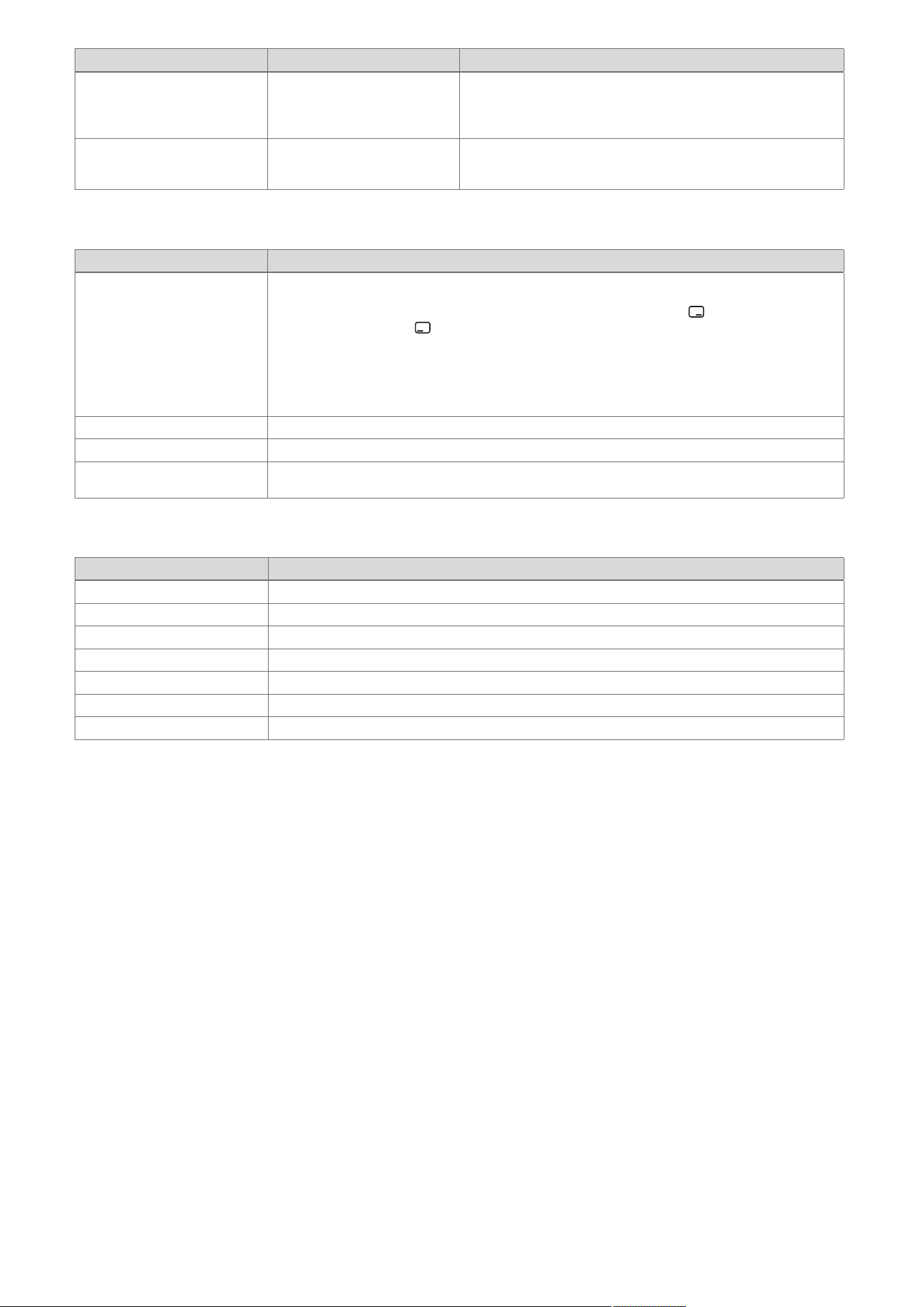
0020244997_07 Installation and maintenance instructions 63
Code/meaning Possible cause Measure
LED actoSTOR Modul
actoSTOR communication
status
actoSTOR communication
status: Not connected, Con-
nection error, Connection
active
1. LED on: Communication OK.
2. LED flashing: Communication not OK.
3. LED off: No power supply.
Communication fault Communication fault between
the display and the PCB in the
electronics box
▶ Check: Cable/plug between the display and the PCB.
F Check programmes – Overview
Check programme Meaning
P.00 Purging The internal pump is cyclically actuated. The heating circuit and the domestic hot water circuit are ad-
aptively purged by automatically switching the circuits using the automatic air vent (the automatic air
vent's cap must be loose). The active circuit is shown in the display. Press once to start purging
the heating circuit. Press once to end the purge programme. Note: The purge programme runs for
7.5 min per circuit and then terminates. Purging the heating circuit: Prioritising diverter valve in heat-
ing position, actuation of internal pump for 9 cycles: 30 sec. on, 20 sec. off. Display: Active heating
circuit. Purging the domestic hot water circuit: After the above-mentioned cycles have run or the right-
hand selection button has been pressed again: Prioritising diverter valve in the domestic hot water
position, actuation of the internal pump as above. Display: Active domestic hot water circuit.
P.01 Maximum load After successful ignition, the product is operated at maximum heat input.
P.02 Minimum load After successful ignition, the product is operated at minimum heat input.
P.06 Filling mode The prioritising diverter valve is moved to the mid-position. The burner and pump are switched off (to
fill or drain the product).
G Function menu – Overview
Function menu Meaning
T.01 Internal pump The internal pump is switched on and off.
T.02 3-way valve The prioritising diverter valve is moved to the heating or domestic hot water position.
T.03 Fan The fan is switched on and off. The fan runs at maximum rotational speed.
T.04 Cylinder charging pump The cylinder charging pump is switched on and off.
T.05 Circulation pump The circulation pump is switched on and off.
T.06 External pump The external pump is switched on and off.
T.08 Burner The product starts up and switches to minimum load. The flow temperature is shown in the display.
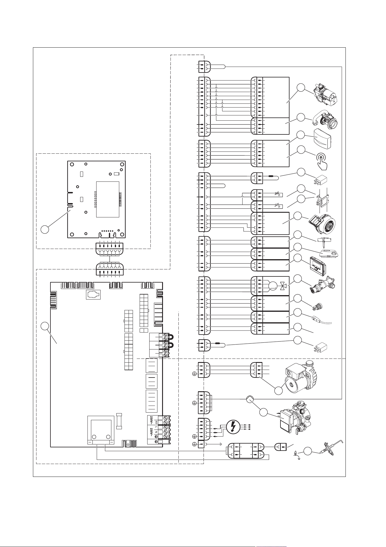
64 Installation and maintenance instructions 0020244997_07
H Wiring diagrams
H.1 Wiring diagram, product for heating mode only, 12 - 35 kW
X18
X51
X20
X1
24V
230V~
24V
230V~
X41
X25
6
5
4
3
2
1
X22
6
5
4
3
16
1
12
4
X2
13
11
14
3
1
4
L
N
L
RT
*
N
X16
L
N
1
2
3
8
17
7
18
6
4
3
1
M
C1
C2
16
4
3
17
5
7
8
5
4
2
1
Masse
PWM
Hallsignal
+24V
15
2
13
12
Burner Off BUSRT 24V
X100
12
6
9
4
2
10
1
11
3
5
1
2
7
8
2
4
X24
17
3
X30
X40 X51 X35
X31
X22
X90
2
1
T2
Fuse
X12
X25
X2
Opt
X16
Fan
X11
X18
CH Pump
X24
X20
–
+
24V=
RT BUS
Burner
off
X100
X1
X41
5
X51
2
1
10
20
19
3
4
17
18
14
15
13
12
11
8
16
6
7
9
21
1 Main PCB
2 Control panel PCB
3 Gas valve assembly
4 Mass flow sensor

0020244997_07 Installation and maintenance instructions 65
5 Outdoor temperature sensor, flow temperature
sensor (optional, external), DCF receiver
6 Circulation pump remote control
7 Power coding resistor
8 Return temperature sensor
9 Flow temperature sensor
10 Fan
11 Surface-mounted thermostat/burner off
12 24 V DC room thermostat
13 Bus connection (digital room thermostat/control)
14 Prioritising diverter valve
15 Water pressure sensor
16 Cylinder temperature sensor
17 Cylinder contact "C1/C2"
18 Gas group coding resistor
19 Additional relay (select via D.026)
20 Internal pump
21 Ignition electrode
* Depending on product type
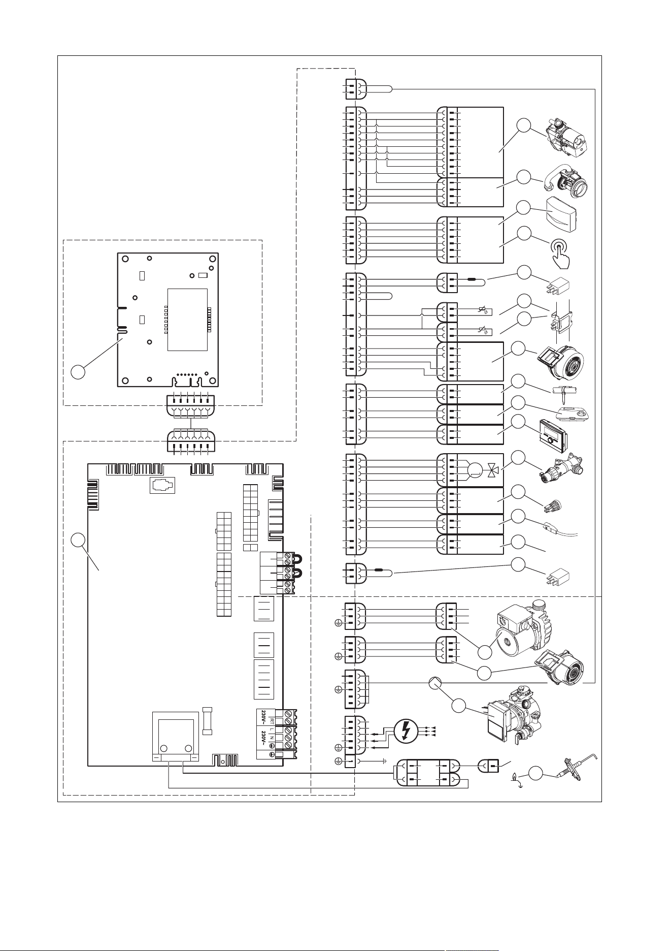
66 Installation and maintenance instructions 0020244997_07
H.2 Wiring diagram, product for heating mode only, ≥ 37 kW
X18
X51
X20
X1
X11
24V
230V~
24V
230V~
X41
X25
6
5
4
3
2
1
X22
6
5
4
3
16
1
12
4
X2
13
11
14
3
1
4
L
N
L
N
L
RT
*
N
X16
L
N
1
2
3
1
2
3
8
17
7
18
6
4
3
1
M
C1
C2
16
4
3
17
5
7
8
5
4
2
1
Masse
PWM
Hallsignal
+24V
15
2
13
12
Burner Off BUSRT 24V
X100
12
6
9
4
2
10
1
11
3
5
1
2
7
8
2
4
X24
17
3
X30
X40 X51 X35
X31
X22
X90
2
1
T2
Fuse
X12
X25
X2
Opt
X16
Fan
X11
X18
CH Pump
X24
X20
–
+
24V=
RT BUS
Burner
off
X100
X1
X41
5
X51
2
1
10
20
10
19
3
4
17
18
14
15
13
12
11
8
16
6
7
9
21
1 Main PCB
2 Control panel PCB
3 Gas valve assembly
4 Mass flow sensor
5 Outdoor temperature sensor, flow temperature
sensor (optional, external), DCF receiver
6 Circulation pump remote control
7 Power coding resistor
8 Return temperature sensor

0020244997_07 Installation and maintenance instructions 67
9 Flow temperature sensor
10 Fan
11 Surface-mounted thermostat/burner off
12 24 V DC room thermostat
13 Bus connection (digital room thermostat/control)
14 Prioritising diverter valve
15 Water pressure sensor
16 Cylinder temperature sensor
17 Cylinder contact "C1/C2"
18 Gas group coding resistor
19 Additional relay (select via D.026)
20 Internal pump
21 Ignition electrode
* Depending on product type
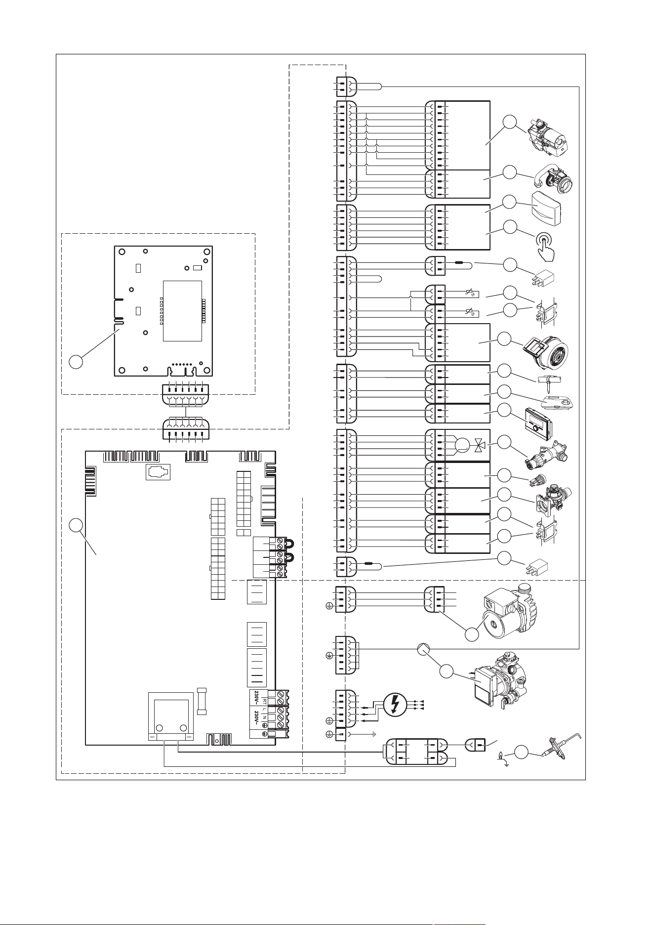
68 Installation and maintenance instructions 0020244997_07
H.3 Wiring diagram, product with integrated domestic hot water generation, 12–35 kW
X18
X51
X20
X1
24V
230V~
24V
230V~
X41
X25
6
5
4
3
2
1
X22
6
5
4
3
5
1
12
4
X2
13
11
14
2
6
3
3
1
4
2
1
3
L
N
X16
L
N
1
2
3
8
17
7
18
6
4
3
1
M
16
4
3
17
5
7
8
5
4
2
1
Masse
PWM
Hallsignal
+24V
15
2
13
12
Burner Off BUSRT 24V
X100
12
6
9
4
2
10
1
11
3
5
1
2
7
8
2
4
X24
17
3
X30
X40 X51 X35
X31
X22
X90
2
1
T2
Fuse
X12
X25
X2
Opt
X16
Fan
X11
X18
CH Pump
X24
X20
–
+
24V=
RT BUS
Burner
off
X100
X1
X41
5
X51
L
RT
*
N
2
1
10
21
20
3
4
18
19
14
15
16
13
12
11
8
17
6
7
9
22
1 Main PCB
2 Control panel PCB
3 Gas valve assembly
4 Mass flow sensor
5 Outdoor temperature sensor, flow temperature
sensor (optional, external), DCF receiver
6 Circulation pump remote control
7 Power coding resistor
8 Return temperature sensor

0020244997_07 Installation and maintenance instructions 69
9 Flow temperature sensor
10 Fan
11 Surface-mounted thermostat/burner off
12 24 V DC room thermostat
13 Bus connection (digital room thermostat/control)
14 Prioritising diverter valve
15 Water pressure sensor
16 Impeller sensor
17 Warm-start sensor
18 Domestic hot water sensor
19 Gas group coding resistor
20 Additional relay (select via D.026)
21 Internal pump
22 Ignition electrode
* Depending on product type
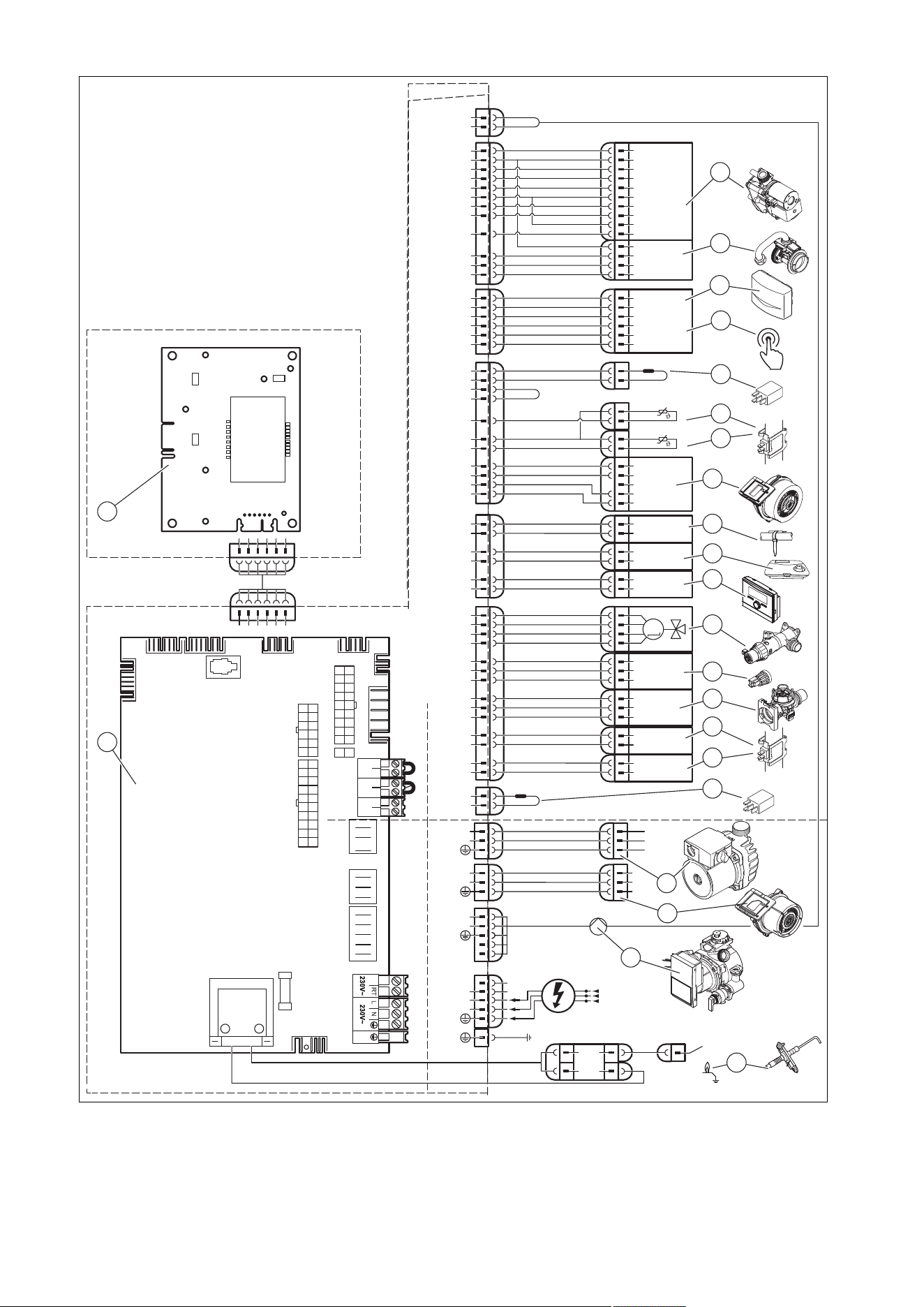
70 Installation and maintenance instructions 0020244997_07
H.4 Wiring diagram, product with integrated domestic hot water generation, ≥ 37 kW
X18
X51
X20
X1
24V
230V~
24V
230V~
X41
X25
6
5
4
3
2
1
X22
6
5
4
3
5
1
12
4
X2
13
11
14
2
6
3
3
1
4
2
1
3
L
N
X16
L
N
1
2
3
8
17
7
18
6
4
3
1
M
16
4
3
17
5
7
8
5
4
2
1
Masse
PWM
Hallsignal
+24V
15
2
13
12
Burner Off BUSRT 24V
X100
12
6
9
4
2
10
1
11
3
5
1
2
7
8
2
4
X24
17
3
X30
X40 X51 X35
X31
X22
X90
2
1
T2
Fuse
X12
X25
X2
Opt
X16
Fan
X11
X18
CH Pump
X24
X20
–
+
24V=
RT BUS
Burner
off
X100
X1
X41
5
X51
L
RT
*
N
X11
L
N
1
2
3
2
1
10
21
20
3
4
18
19
14
15
16
13
12
11
8
17
6
7
9
22
10
1 Main PCB
2 Control panel PCB
3 Gas valve assembly
4 Mass flow sensor
5 Outdoor temperature sensor, flow temperature
sensor (optional, external), DCF receiver
6 Circulation pump remote control
7 Power coding resistor
8 Return temperature sensor

0020244997_07 Installation and maintenance instructions 71
9 Flow temperature sensor
10 Fan
11 Surface-mounted thermostat/burner off
12 24 V DC room thermostat
13 Bus connection (digital room thermostat/control)
14 Prioritising diverter valve
15 Water pressure sensor
16 Impeller sensor
17 Warm start sensor
18 Domestic hot water sensor
19 Gas group coding resistor
20 Additional relay (select via D.026)
21 Internal pump
22 Ignition electrode
* Depending on product type
72 Installation and maintenance instructions 0020244997_07
I Commissioning Checklist
© Heating and Hotwater Industry Council (HHIC)
www.centralheating.co.uk
* All installations in England and Wales must be notied to Local Authority Building Control (LABC) either directly or through a
Competent Persons Scheme. A Building Regulations Compliance Certicate will then be issued to the customer.
www.hhic.co.uk
Benchmark Commissioning &
Warranty Validation Service Record
It is a requirement that the boiler is installed and commissioned to the manufacturers’
instructions and the data elds on the commissioning checklist completed in full.
To instigate the boiler warranty the boiler needs to be registered with the
manufacturer within one month of the installation. The warranty rests with the
end-user (consumer), and they should be made aware it is ultimately their
responsibility to register with the manufacturer, within the allotted time period.
It is essential that the boiler is serviced in line with the manufacturers’
recommendations, at least annually. This must be carried out by a competent Gas
Safe registered engineer. The service details should be recorded on the Benchmark
Service and Interim Boiler Work Record and left with the householder. Failure to
comply with the manufacturers’ servicing instructions and requirements will invalidate
the warranty.
This Commissioning Checklist is to be completed in full by the competent person who commissioned the boiler as a means of demonstrating
compliance with the appropriate Building Regulations and then handed to the customer to keep for future reference.
Failure to install and commission according to the manufacturers’ instructions and complete this Benchmark Commissioning Checklist will invalidate the
warranty. This does not affect the customer’s statutory rights.
0020244997_07 Installation and maintenance instructions 73
© Heating and Hotwater Industry Council (HHIC)
www.centralheating.co.uk
GAS BOILER SYSTEM COMMISSIONING CHECKLIST & WARRANTY VALIDATION RECORD
Address:
Boiler make and model:
Boiler serial number:
Commissioned by (PRINT NAME): Gas Safe registration number:
Company name: Telephone number:
Company email: Company address:
Commissioning date:
Heating and hot water system complies with the appropriate Building Regulations? Yes
Boiler Plus requirements (tick the appropriate box(s))
Boiler Plus option chosen for combination boiler in ENGLAND
Weather compensation Smart thermostat with automisation and optimisation
Load compensation Flue Gas Heat Recovery
Time and temperature control to hot water Cylinder thermostat and programmer/timer Combination boiler
Zone valves pre-existing Fitted Not required
Thermostatic radiator valves pre-existing Fitted Not required
Automatic bypass to system pre-existing Fitted Not required
pre-existing Fitted Not required
Water quality
instructions Yes
What system cleaner was used? Brand: Product:
What inhibitor was used? Brand: Product:
pre-existing Fitted Not required
CENTRAL HEATING MODE measure and record (as appropriate)
Gas rate (for combination boilers complete DHW mode gas rate) m
3/
hr or ft
3
/hr
Central heating output left at factory settings? Yes No
If no, what is the maximum central heating output selected? kW
Dynamic gas inlet pressure mbar
°C
Central heating return temperature °C
System correctly balanced/rebalanced? Yes
COMBINATION BOILERS ONLY
Is the installation in a hard water area (above 200ppm)? Yes No
Water scale reducer/softener pre-existing Fitted Not required
Brand: Product:
Yes No
If yes- DHW expansion vessel pre-existing Fitted Not required
Pressure reducing valve pre-existing Fitted Not required
DOMESTIC HOT WATER MODE Measure and record
Gas rate m
3/
hr or ft
3
/hr
Dynamic gas inlet pressure at maximum rate mbar
Cold water inlet temperature °C
Hot water has been checked at all outlets Yes Temperature °C
CONDENSATE DISPOSAL
The condensate drain has been installed in accordance with the manufacturers’ instructions and/or BS5546/BS6798 Yes
Point of termination Internal External (only where internal termination impractical)
Method of disposal Gravity Pumped
ALL INSTALLATIONS
Record the following
At max rate: CO ppm CO
2
%CO/CO
2
Ratio
At min rate (where possible) CO ppm CO
2
%CO/CO
2
Ratio
instructions, and readings are correct? Yes
The operation of the boiler and system controls have been demonstrated to and understood by the customer Yes
The manufacturers’ literature, including Benchmark Checklist and Service Record, has been explained and left with the customer Yes
Commissioning Engineer’s signature
Customer’s signature
Time, temperature control and boiler interlock provided for central heating and hot water Yes
74 Installation and maintenance instructions 0020244997_07
© Heating and Hotwater Industry Council (HHIC)
www.centralheating.co.uk
SERVICE & INTERIM BOILER WORK RECORD
It is recommended that your boiler and heating system are regularly serviced and maintained, in line with manufacturers’ instructions, and that the appropriate service /
interim work record is completed.
Service provider
When completing a service record (as below), please ensure you have carried out the service as described in the manufacturers’ instructions. Always use the
SERVICE/INTERIM WORK ON BOILER delete as appropriate
Date:
Engineer name: Company name:
Telephone N
o
: Gas Safe registration N
o
:
Max rate CO ppm CO
²
% CO/CO
²
Min rate CO ppm CO
²
% CO/CO
²
undertaken in accordance with manufacturers’
instructions, and readings are correct?”
yes
Gas rate: m
3
/h OR ft
3
/h
delete as appropriate Yes No
System inhibitor concentration has been checked and
appropriate action taken, in accordance with BS 7593
and boiler manufacturers’ instructions. *
yes n/a
Comments:
Signature:
instructions and BS 7593. It is only acceptable to not have undertaken this if the service engineers
attendance visit was in between annual services to attend a non-water facing component.
instructions and BS 7593. It is only acceptable to not have undertaken this if the service engineers
attendance visit was in between annual services to attend a non-water facing component.
instructions and BS 7593. It is only acceptable to not have undertaken this if the service engineers
attendance visit was in between annual services to attend a non-water facing component.
instructions and BS 7593. It is only acceptable to not have undertaken this if the service engineers
attendance visit was in between annual services to attend a non-water facing component.
instructions and BS 7593. It is only acceptable to not have undertaken this if the service engineers
attendance visit was in between annual services to attend a non-water facing component.
instructions and BS 7593. It is only acceptable to not have undertaken this if the service engineers
attendance visit was in between annual services to attend a non-water facing component.
SERVICE/INTERIM WORK ON BOILER delete as appropriate
Date:
Engineer name: Company name:
Telephone N
o
: Gas Safe registration N
o
:
Max rate CO ppm CO
²
% CO/CO
²
Min rate CO ppm CO
²
% CO/CO
²
undertaken in accordance with manufacturers’
instructions, and readings are correct?”
yes
Gas rate: m
3
/h OR ft
3
/h
delete as appropriate Yes No
System inhibitor concentration has been checked and
appropriate action taken, in accordance with BS 7593
and boiler manufacturers’ instructions. *
yes n/a
Comments:
Signature:
0020244997_07 Installation and maintenance instructions 75
© Heating and Hotwater Industry Council (HHIC)
www.centralheating.co.uk
SERVICE & INTERIM BOILER WORK RECORD
It is recommended that your boiler and heating system are regularly serviced and maintained, in line with manufacturers’ instructions, and that the appropriate service /
interim work record is completed.
Service provider
When completing a service record (as below), please ensure you have carried out the service as described in the manufacturers’ instructions. Always use the
SERVICE/INTERIM WORK ON BOILER delete as appropriate
Date:
Engineer name: Company name:
Telephone N
o
: Gas Safe registration N
o
:
Max rate CO ppm CO
²
% CO/CO
²
Min rate CO ppm CO
²
% CO/CO
²
undertaken in accordance with manufacturers’
instructions, and readings are correct?”
yes
Gas rate: m
3
/h OR ft
3
/h
delete as appropriate Yes No
System inhibitor concentration has been checked and
appropriate action taken, in accordance with BS 7593
and boiler manufacturers’ instructions. *
yes n/a
Comments:
Signature:
instructions and BS 7593. It is only acceptable to not have undertaken this if the service engineers
attendance visit was in between annual services to attend a non-water facing component.
instructions and BS 7593. It is only acceptable to not have undertaken this if the service engineers
attendance visit was in between annual services to attend a non-water facing component.
instructions and BS 7593. It is only acceptable to not have undertaken this if the service engineers
attendance visit was in between annual services to attend a non-water facing component.
instructions and BS 7593. It is only acceptable to not have undertaken this if the service engineers
attendance visit was in between annual services to attend a non-water facing component.
instructions and BS 7593. It is only acceptable to not have undertaken this if the service engineers
attendance visit was in between annual services to attend a non-water facing component.
instructions and BS 7593. It is only acceptable to not have undertaken this if the service engineers
attendance visit was in between annual services to attend a non-water facing component.
SERVICE/INTERIM WORK ON BOILER delete as appropriate
Date:
Engineer name: Company name:
Telephone N
o
: Gas Safe registration N
o
:
Max rate CO ppm CO
²
% CO/CO
²
Min rate CO ppm CO
²
% CO/CO
²
undertaken in accordance with manufacturers’
instructions, and readings are correct?”
yes
Gas rate: m
3
/h OR ft
3
/h
delete as appropriate Yes No
System inhibitor concentration has been checked and
appropriate action taken, in accordance with BS 7593
and boiler manufacturers’ instructions. *
yes n/a
Comments:
Signature:
SERVICE/INTERIM WORK ON BOILER delete as appropriate
Date:
Engineer name: Company name:
Telephone N
o
: Gas Safe registration N
o
:
Max rate CO ppm CO
²
% CO/CO
²
Min rate CO ppm CO
²
% CO/CO
²
undertaken in accordance with manufacturers’
instructions, and readings are correct?”
yes
Gas rate: m
3
/h OR ft
3
/h
delete as appropriate Yes No
System inhibitor concentration has been checked and
appropriate action taken, in accordance with BS 7593
and boiler manufacturers’ instructions. *
yes n/a
Comments:
Signature:
SERVICE/INTERIM WORK ON BOILER delete as appropriate
Date:
Engineer name: Company name:
Telephone N
o
: Gas Safe registration N
o
:
Max rate CO ppm CO
²
% CO/CO
²
Min rate CO ppm CO
²
% CO/CO
²
undertaken in accordance with manufacturers’
instructions, and readings are correct?”
yes
Gas rate: m
3
/h OR ft
3
/h
delete as appropriate Yes No
System inhibitor concentration has been checked and
appropriate action taken, in accordance with BS 7593
and boiler manufacturers’ instructions. *
yes n/a
Comments:
Signature:
SERVICE/INTERIM WORK ON BOILER delete as appropriate
Date:
Engineer name: Company name:
Telephone N
o
: Gas Safe registration N
o
:
Max rate CO ppm CO
²
% CO/CO
²
Min rate CO ppm CO
²
% CO/CO
²
undertaken in accordance with manufacturers’
instructions, and readings are correct?”
yes
Gas rate: m
3
/h OR ft
3
/h
delete as appropriate Yes No
System inhibitor concentration has been checked and
appropriate action taken, in accordance with BS 7593
and boiler manufacturers’ instructions. *
yes n/a
Comments:
Signature:
SERVICE/INTERIM WORK ON BOILER delete as appropriate
Date:
Engineer name: Company name:
Telephone N
o
: Gas Safe registration N
o
:
Max rate CO ppm CO
²
% CO/CO
²
Min rate CO ppm CO
²
% CO/CO
²
undertaken in accordance with manufacturers’
instructions, and readings are correct?”
yes
Gas rate: m
3
/h OR ft
3
/h
delete as appropriate Yes No
System inhibitor concentration has been checked and
appropriate action taken, in accordance with BS 7593
and boiler manufacturers’ instructions. *
yes n/a
Comments:
Signature:
76 Installation and maintenance instructions 0020244997_07
J Commissioning Flow Chart
PRIOR TO CO AND COMBUSTION RATIO CHECK
The boiler manufacturer’s installation instructions should have been followed, gas type verified and gas
supply pressure/rate checked as required prior to commissioning.
As part of the installation process, especially where a flue has been fitted by persons other than the
boiler installer, visually check the integrity of the whole flue system to confirm that all components are
correctly assembled, fixed and supported. Check that manufacturer’s max. flue lengths have not been
exceeded and all guidance has been followed (e.g. Gas Safe Technical Bulletin TB008).
The flue gas analyser should be of the correct type, as specified by BS 7967
Prior to its use, the flue gas analyser should have been maintained and calibrated as specified by the
manufacturer. The installer must have the relevant competence for use of the analyser.
Check and zero the analyser IN FRESH AIR as per analyser manufacturer’s instructions.
NOTE
THE AIR GAS RATIO VALVE IS FACTORY
SET AND MUST NOT BE ADJUSTED
DURING COMMISSIONING UNLESS THIS
ACTION IS RECOMMENDED FOLLOWING
CONTACT WITH THE MANUFACTURER.
If any such adjustment is recommended and
further checking of the boiler is required the
installer/service engineer must be competent
to carry out this work and to use the flue gas
analyser accordingly.
If the boiler requires conversion to operate with
a different gas family (e.g. conversion from
natural gas to LPG) separate guidance will be
provided by the boiler manufacturer
CARRY OUT FLUE INTEGRITY CHECK USING ANALYSER
Insert analyser probe into air inlet test point and allow readings to stabilise.
NOTE - where no air inlet test point is provided then a flue integrity check
with the analyser is not possible. The installer should verify that flue
integrity has been visually checked in accordance with the “Prior to
CO and combustion ratio check” box above before proceeding to the
“Check CO and combustion ratio at maximum rate” stage below.
SET BOILER TO MINIMUM RATE
In accordance with boiler instructions, set boiler to operate at minimum rate (to
minimum load condition). Allow sufficient time for combustion to stabilise.
NOTE - If manufacturer’s instructions do not specify how to set boiler to minimum
rate contact Technical Helpline for advice.
CHECK CO AND COMBUSTION RATIO AT MINIMUM RATE
With boiler still set at minimum rate, insert analyser probe into flue gas sampling
point. Allow readings to stabilise before recording.
NOTE - If no flue gas sampling point is present and the correct procedure is not
specified in the manual, consult boiler manufacturer for guidance.
CHECK CO AND COMBUSTION RATIO AT MAX. RATE
With boiler still set at maximum rate, insert analyser probe into flue gas
sampling point. Allow readings to stabilise before recording.
NOTE - If no flue gas sampling point is present and the correct procedure is
not specified in the manual, consult boiler manufacturer for guidance.
SET BOILER TO MAXIMUM RATE
In accordance with boiler instructions, set boiler to operate at max. rate
(full load condition). Allow sufficient time for combustion to stabilise.
NOTE - Do not insert analyser probe during this period to avoid
possible “flooding” of sensor.
Is
CO less than
350ppm and
CO/CO
2
ratio
less than 0.004
Is
O
2
20.6%
and
CO
2
< 0.2%
Is
CO less than
350ppm and
CO/CO
2
ratio
less than 0.004
BOILER IS OPERATING SATISFACTORILY
no further actions required.
Ensure test points are capped, boiler case is correctly replaced and
all other commissioning procedures are completed.
Complete Benchmark Checklist, recording CO and combustion ratio
readings as required.
TURN OFF APPLIANCE AND CALL
MANUFACTURER’S TECHNICAL HELPLINE
FOR ADVICE.
THE APPLIANCE MUST NOT BE
COMMISSIONED UNTIL PROBLEMS ARE
IDENTIFIED AND RESOLVED.
VERIFY FLUE INTEGRITY
Analyser readings indicate that combustion products
and inlet air must be mixing. Further investigation of
the flue is therefore required.
Check that flue components are assembled, fixed
and supported as per boiler/flue manufacturer’s
instructions.
Check that flue and flue terminal are not obstructed.
Is
CO
less than
335ppm
and
CO/CO
2
ratio less
than 0.004
Is
O
2
20.6%
and
CO
2
< 0.2%
Check all seals around the appliance burner,
internal flue seals, door and case seals.
Rectify where necessary.
TURN OFF APPLIANCE AND CALL
MANUFACTURER’S TECHNICAL HELPLINE
FOR ADVICE.
THE APPLIANCE MUST NOT BE
COMMISSIONED UNTIL PROBLEMS ARE
IDENTIFIED AND RESOLVED. IF
COMMISSIONING CANNOT BE FULLY
COMPLETED, THE APPLIANCE MUST BE
DISCONNECTED FROM THE GAS SUPPLY IN
ACCORDANCE WITH THE GSIUR.
NOTE: Check and record CO and combustion ratio
at both max. and min. rate before contacting the
manufacturer.
NO
NO
NO
NO
NO
YES
YES
YES
YES
YES

0020244997_07 Installation and maintenance instructions 77
Index
A
Air ratio setting .................................................................... 37
Air/flue pipe ......................................................................... 28
Air/flue pipe, horizontal wall duct......................................... 22
Air/flue pipe, type C13 ......................................................... 22
Air/flue pipe, type C33 ......................................................... 22
Air/flue pipe, vertical roof duct ............................................. 22
Article number ............................................................... 15–16
Automatic air vent................................................................ 35
Auxiliary relay ...................................................................... 32
B
Burner anti-cycling time....................................................... 39
Burner anti-cycling time, resetting ....................................... 39
Burner anti-cycling time, setting .......................................... 39
Burner, checking ................................................................. 43
Burner, replacing ................................................................. 46
Bypass valve, setting........................................................... 40
C
CE marking.......................................................................... 15
Check programmes ....................................................... 32–33
Checking, pre-charge pressure for the internal expansion
vessel .................................................................................. 44
Circulation pump ................................................................. 30
CO₂ content, checking......................................................... 37
CO₂ content, setting ............................................................ 37
Cold water connection......................................................... 25
Cold water inlet strainer, cleaning ....................................... 44
Comfort mode...................................................................... 32
Comfort protection mode..................................................... 45
Compact thermal module ...................................................... 6
Compact thermal module, installing .................................... 44
Compact thermal module, removing ................................... 42
Component test ................................................................... 42
Condensate discharge pipe................................................. 25
Condensate siphon ....................................................... 34, 44
Condensate trap............................................................ 34, 44
Connection dimensions ....................................................... 18
Contact details..................................................................... 32
Control, connecting ............................................................. 29
Corrugated gas pipe.............................................................. 6
D
Decommissioning................................................................ 50
Decommissioning, temporarily ............................................ 50
Diagnostics codes, calling up.............................................. 39
Disposal, packaging ............................................................ 50
Disposing of the packaging ................................................. 50
Documents .......................................................................... 15
Drain pipe, expansion relief valve ....................................... 25
E
Electronics box, closing....................................................... 28
Electronics self-test ............................................................. 42
F
Fan, replacing...................................................................... 46
Fault codes.......................................................................... 45
Fault memory, calling up ..................................................... 45
Fault memory, deleting........................................................ 45
Fault messages ................................................................... 45
Filling ................................................................................... 35
Filling mode ......................................................................... 32
Frost protection ................................................................... 17
Function menu............................................................... 42, 63
G
Gas conversion ................................................................... 36
Gas Council Number ........................................................... 15
Gas family check, performing.............................................. 33
Gas flow rate ....................................................................... 36
Gas group............................................................................ 24
Gas injector ......................................................................... 47
Gas setting .......................................................................... 36
Gas type .............................................................................. 24
Gas valve assembly ............................................................ 46
Gas valve assembly, replacing............................................ 47
Guarantee and Customer Service......................................... 7
H
Handing over to the end user.............................................. 41
Heat exchanger, cleaning.................................................... 43
Heat exchanger, replacing .................................................. 48
Heating flow......................................................................... 25
Heating partial load ............................................................. 32
Heating return...................................................................... 25
Hot water connection........................................................... 25
Hot water temperature......................................................... 32
I
Identification plate ............................................................... 15
Inspection work, carrying out............................................... 42
Inspection work, completing................................................ 45
Installation assistant, ending ............................................... 32
Installation assistants, restarting ......................................... 32
Installer level, calling up ...................................................... 31
Intended use.......................................................................... 4
Internal expansion vessel, replacing ................................... 49
Isolators............................................................................... 50
K
Kammerbelüftung................................................................ 19
L
Language ............................................................................ 32
Leak detection spray ............................................................. 6
Leak-tightness ......................................................... 38, 45, 50
Liquid gas ........................................................................ 6, 24
M
Maintenance interval, setting............................................... 39
Maintenance work, carrying out .......................................... 42
Maintenance work, completing............................................ 45
Manometer .......................................................................... 16
Mass flow sensor, replacing................................................ 47
Minimum clearance ............................................................. 19
Multi-functional module ....................................................... 32
O
Operating concept ............................................................... 31
Overheating protection ........................................................ 17
P
PCB and display, replacing ................................................. 49
PCB or display, replacing .................................................... 49
Power supply....................................................................... 29
Pre-charge pressure for the internal expansion vessel,
checking .............................................................................. 44
Preparing, maintenance work.............................................. 42
Preparing, repair work ......................................................... 45
Product dimensions............................................................. 18
Product, draining ................................................................. 44
Product, switching off .......................................................... 50
Pump output, setting ........................................................... 40
Pump, remaining feed head ................................................ 40
Purging ................................................................................ 35

78 Installation and maintenance instructions 0020244997_07
R
Regulations ........................................................................... 6
Remaining feed head, pump ............................................... 40
Repair work, completing...................................................... 50
Repair work, preparing .................................................. 42, 45
S
Safety devices ..................................................................... 17
Scale ................................................................................... 24
Scale deposition .................................................................. 24
Scope of delivery................................................................. 18
Self-test ......................................................................... 42, 63
Serial number ...................................................................... 16
Service message................................................................. 45
Side section, installing......................................................... 23
Side section, removing ........................................................ 23
Spare parts.......................................................................... 45
Status codes........................................................................ 31
Switching off ........................................................................ 32
Switching on ........................................................................ 32
T
Target feed temperature...................................................... 32
Technical data ....................................................................... 8
Telephone number, competent person ............................... 32
Test programmes .......................................................... 32, 63
Treating the heating water................................................... 33
U
Unit configuration ................................................................ 39
Unit connection piece for the air/flue pipe, removing .......... 28
Unit connection piece for the air/flue pipe, replacing .......... 28
Unit connection piece, 80/125 mm diameter, installing....... 28
V
Validity of the instructions.................................................... 15
Venturi ................................................................................. 46
Venturi, replacing ................................................................ 47
W
Weight ................................................................................. 22


Supplier
Vaillant Ltd.
Nottingham Road Belper Derbyshire DE56 1JT
Telephone 0330 100 3143
[email protected] www.vaillant.co.uk
Publisher/manufacturer
Vaillant GmbH
Berghauser Str. 40 D-42859 Remscheid
Tel. +49 2191 18 0 Fax +49 2191 18 2810
[email protected] www.vaillant.de
© These instructions, or parts thereof, are protected by copyright and may be reproduced or distributed only with
the manufacturer's written consent.
Subject to technical modifications.
0020244997_07