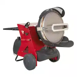
45.5KW INFRARED PARAFFIN/KEROSENE/DIESEL
HEATER
MODEL NO: IR55.V2
Thank you for purchasing a Sealey product. Manufactured to a high standard, this product will, if used according to these instructions,
and properly maintained, give you years of trouble free performance.
IMPORTANT: PLEASE READ THESE INSTRUCTIONS CAREFULLY. NOTE THE SAFE OPERATIONAL REQUIREMENTS, WARNINGS & CAUTIONS. USE
THE PRODUCT CORRECTLY AND WITH CARE FOR THE PURPOSE FOR WHICH IT IS INTENDED. FAILURE TO DO SO MAY CAUSE DAMAGE AND/OR
PERSONAL INJURY AND WILL INVALIDATE THE WARRANTY. KEEP THESE INSTRUCTIONS SAFE FOR FUTURE USE.
1. SAFETY
1.1. ELECTRICAL SAFETY
WARNING! It is the user’s responsibility to check the following:
Check all electrical equipment and appliances to ensure that they are safe before using. Inspect power supply leads, plugs and
all electrical connections for wear and damage. Sealey recommend that an RCD (Residual Current Device) is used with all electrical
products. You may obtain an RCD by contacting your local Sealey stockist.
If the product is used in the course of business duties, it must be maintained in a safe condition and routinely PAT (Portable
Appliance Test) tested.
Electrical safety information, it is important that the following information is read and understood.
Ensure that the insulation on all cables and on the appliance is safe before connecting it to the power supply.
Regularly inspect power supply cables and plugs for wear or damage and check all connections to ensure that they are secure.
Important: Ensure that the voltage rating on the appliance suits the power supply to be used and that the plug is tted with the
correct fuse - see fuse rating in these instructions.
8 DO NOT pull or carry the appliance by the power cable.
8 DO NOT pull the plug from the socket by the cable.
8 DO NOT use worn or damaged cables, plugs or connectors. Ensure that any faulty item is repaired or is
replaced immediately by a qualied electrician.
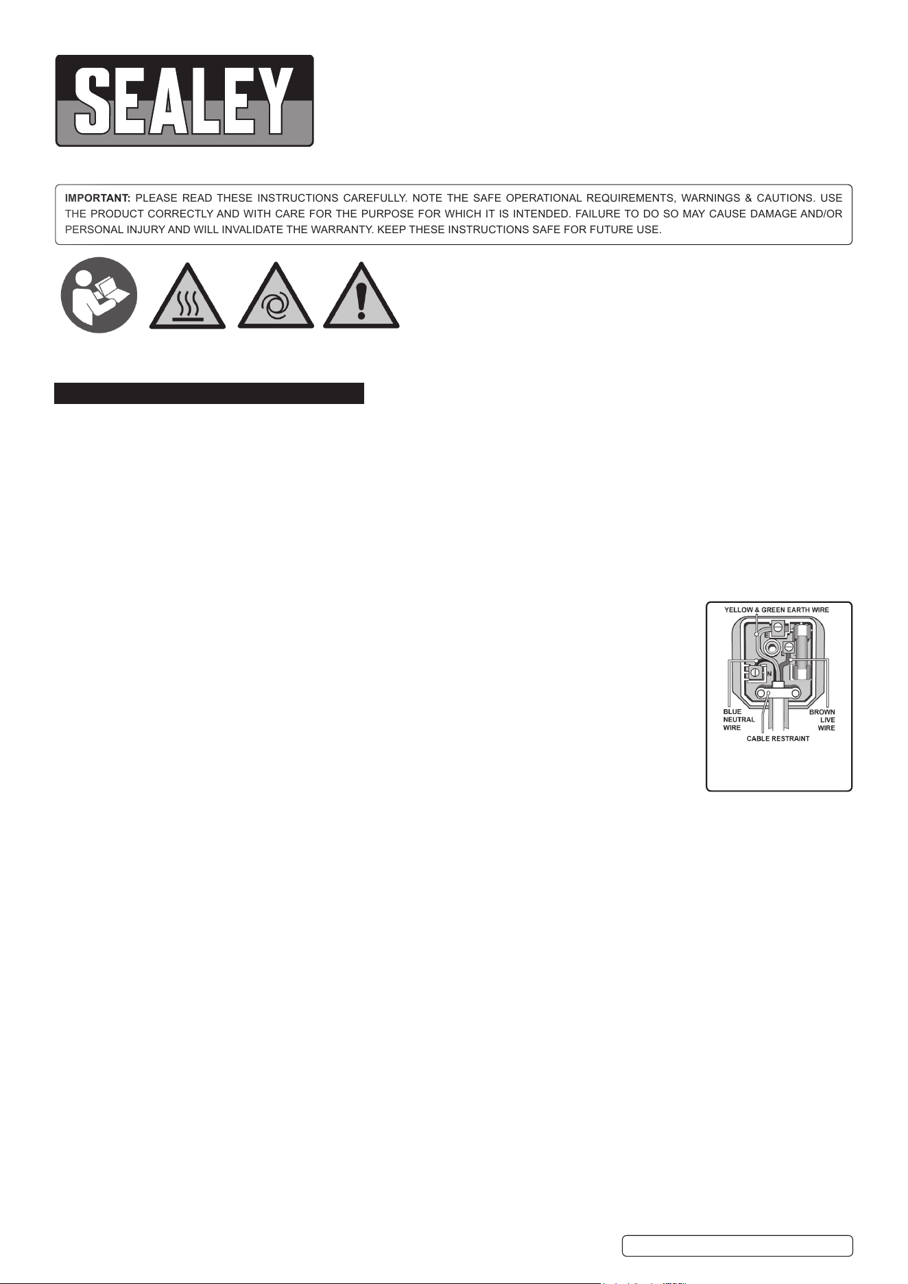
This product is tted with a BS1363/A 13 Amp 3 pin plug.
If the cable or plug is damaged during use, switch off the electricity supply and remove from use.
Ensure that repairs are carried out by a qualied electrician.
Replace a damaged plug with a BS1363/A 13 Amp 3 pin plug. If in doubt contact a qualied electrician.
a) Connect the GREEN/YELLOW earth wire to the earth terminal ‘E’.
b) Connect the BROWN live wire to the live terminal ‘L’.
c) Connect the BLUE neutral wire to the neutral terminal ‘N’.
Ensure that the cable outer sheath extends inside the cable restraint and that the restraint is tight.
Sealey recommend that repairs are carried out by a qualied electrician.
If an extension reel is used it should be fully unwound before connection. A reel with an RCD fitted is preferred since any appliance
plugged into it will be protected. The cable core section is important and should be at least 1.5mm², but to be absolutely sure that the
capacity of the reel is suitable for this product and for others which may be used in the other output sockets, we recommend the use
of 2.5mm² section cable.
1.2. GENERAL SAFETY
WARNING! THIS HEATER IS FOR PROFESSIONAL USE. IT HAS BEEN CAREFULLY DESIGNED FOR MOBILE AND
TEMPORARY PROFESSIONAL APPLICATIONS.
IT HAS NOT BEEN DESIGNED FOR DOMESTIC USE NOR FOR COMFORT HEATING AND SHOULD NEVER BE USED TO HEAT
CLOSED ROOMS WITHOUT ADEQUATE VENTILATION.
▲ DANGER! Risk of carbon monoxide poisoning. Failure to provide proper ventilation could result in serious illness or death.
9 Check that the heater is in sound condition and good working order. Take immediate action to repair or replace damaged parts.
9 Use recommended parts only. Unauthorised parts may be dangerous and will invalidate the warranty.
9 Only use parafn, diesel or kerosene to fuel this heater, in accordance with instructions contained in this manual.
9 Locate heater on a level and stable surface.
WARNING! Only use heater in well ventilated areas. Ensure continuous ventilation is provided to the heater operating area via
windows and doors etc. If people are not required to be present in the heated area, the volume of air to be heated (mtr³)/heat output
kW) ratio must be at least 10:1 and people must be advised not to remain in the heated area for prolonged periods. If people are
required to be present in the heated area, the volume of air to be heated (mtr³)/heat output (kW) ratio must be at least 30:1. Ventilation
must be to the outside of the premises in which the heater is to be operated. The total open area (mtr²) must be at least 0.003 times
the total heat output (kW). The volume concentration of
oxygen (O
²
) in the heated room, must always remain above 17%.
WARNING! DO NOT use the heater near flammable material, liquids, solids, gases or compressed gas cylinders etc.
8 DO NOT stand or place any object less than 3mtr from the heater output and keep the heater a minimum of 2mtr from any walls or
objects.
8 DO NOT use the heater in closed rooms, living areas, basements or below ground level.
8 DO NOT allow untrained persons to operate the heater and DO NOT operate the heater without the safety guard.
Original Language Version
© Jack Sealey Limited
Warning:
Automatic
start up
Warning:
Hot
surface
Refer to
instruction
manual
Warning:
Professional
use only
RECOMMENDED
FUSE RATING: 13AMP
IR55.V2 | Issue:1 08/04/20
Original Language Version
© Jack Sealey Limited
8 DO NOT move or handle the heater when hot, without wearing protective gloves. Never move the heater whilst it is operating.
8 DO NOT leave the heater unattended for prolonged periods of time when in use. Switch the heater off and unplug from the mains
before leaving work area.
8 DO NOT ll the fuel tank whilst the heater is running or still hot. DO NOT over-ll the fuel container. Wipe up any spilt fuel immediately.
8 DO NOT obstruct the air inlet (rear) and air outlet (front) of the heater and DO NOT use duct work in front or at the rear of the heater.
8 DO NOT allow children or animals near the heater when in use, or whilst still hot.
WARNING! RISK OF ELECTRIC SHOCK. DO NOT expose the heater to water spray, rain, dripping water or wind.
8 DO NOT operate the heater when you are tired or under the inuence of alcohol, drugs or intoxicating medication.
8 DO NOT touch the heater outlet or cone when in use, or for a period of time after it’s switched off, as these are VERY hot and will
take time to cool down.
8 DO NOT switch the heater off by disconnecting it from the mains. ALWAYS set the switch on the burner to the ‘OFF’ position and allow
the cooling cycle to nish, before disconnecting from the mains.
8 DO NOT use an external fuel tank. Only use the tank that is tted to the heater, and only ll it when the heater has cooled down.
9 Ensure that the heater is correctly turned off
9 When not in use for an extended period, store in a safe, dry area, out of reach of children.
Important: This appliance is not intended for persons (including children) with reduced physical, sensory or mental capabilities, or lack of
experience and knowledge, unless they have been given supervision or instruction concerning use of the appliance by a person
responsible for their safety. Children should be supervised to ensure that they do not play with the appliance.
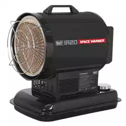
2. INTRODUCTION
Infrared heater suitable for well ventilated applications. Designed to increase heat efciency while eliminating the fragility and brittleness of
ceramic cones. Clean burning unit operates on parafn, kerosene or diesel. Produces an impressive output of 155,252 Btu/hr. 65L Tank allows
a maximum of 15hrs running time. Features electronic ame control with photo resistance sensor. Outer cover cooled by forced air over the
complete surface of the cone. Complies with rigorous standards and is tted with a safety cut-out.
3. SPECIFICATION
Model no ................................................................... IR55.V2
Fuel tank .......................................................................... 65L
Fuel .................................................Parafn/Kerosene/Diesel
Output ............................................... 45.5kW(155,252Btu/hr)
Supply .........................................................................230-5A
Transport wheels .............................................................. yes
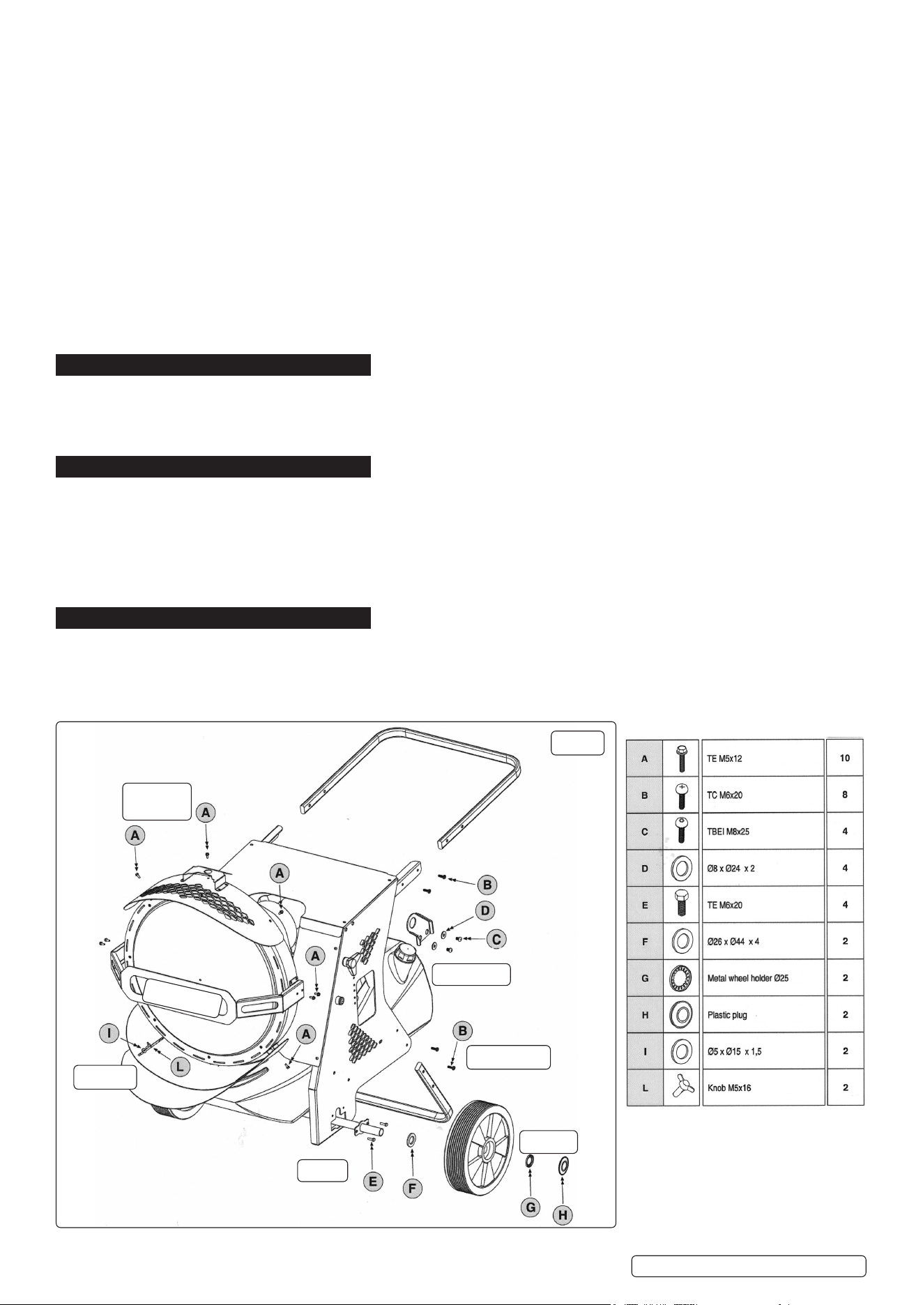
4. SUB ASSEMBLY
The heater will be supplied assembled to a stage with minimal assembly required by the user (fig.A).
4.1. Slide axle through frame and fix with item [E]. Slide on spacers [F] and wheels, retain the wheels with [G] and plug with [H].
4.2. Fix handle bar and heater rear stand with [B]. The heater is now free standing and transportable.
4.3. Fit upper and lower heat deflector shrouds including mid-height front shield with [A]. Fit the lower adjustable deflector with [I] and [L].
4.4. Fit lifting lugs with [C] and [D].
.
Deflector
Rear Stand
Axle
Shield
Lifting lugs
Wheels
Deflector
diffuser
g.A
Table of xings for sub assembly
IR55.V2 | Issue:1 08/04/20
Original Language Version
© Jack Sealey Limited
5. OPERATING CONDITIONS
5.1. FUEL AND AIR SYSTEM: This heater is equipped with an oil pump that operates from an electric motor. The pump forces oil from the
fuel tank, drawing fuel to the nozzle in the burner head. Air also passes through the nozzle via a fan and ducting where it mixes with the
fuel, sprayed into the combustion chamber as a fine mist where it is super-heated and forced out the front of the chamber.
5.2. QUICK-FIRE IGNITION: A transformer sends high voltage to a two pronged spark plug. The spark ignites the fuel/air mixture as it is
sprayed into the combustion chamber.
5.3. ELECTRICAL SYSTEM PROTECTION: The heater’s electrical system is protected by a circuit breaker that protects the system
components from damage. If the heater fails, check the fuse first, and replace if necessary.
5.4. FLAME SENSOR: The heater uses a photocell to see the flame in the combustion chamber. Should the flame extinguish, the sensor will
stop electrical current and the heater will shut off.
5.5. FUEL: The heater operates with paraffin, kerosene or diesel fuel. DO NOT use any other type of fuel.
5.6. When used in the construction or agricultural industries ensure that the safety regulations in force are adhered to with regard to distances
from animals, flammable materials and any other specified substances.
WARNING! Air contaminants taken into the heater may affect the heat output, damage the unit and may cause health problems.
Example: Bodyshop filler dust/paint overspray will damage the motor bearing, clog the filter and compressor and contaminate
the combustion chamber causing flame flutter and health hazards. Please note that any parts damaged by filler dust/paint over
spray will not be covered by warranty. Additionally, a cleaning charge will be made for any heaters damaged by filler dust/paint
over spray.
5.7. VENTILATION
WARNING! Only use the heater in well ventilated areas. Careful consideration must be given to the placing of the heater to provide safe
and comfortable heating. Ensure continuous ventilation is provided to the heater operating area. A ventilation opening must run to the
outside of the premises in which the heater is to be operated.
The heater requires a fresh air opening of at least 2800cm².
For Example:
- A two car garage door should be open at least 11cm.
- A single car garage door should be open at least 16cm.
- Two 76cm windows should be open at least 20cm.
6. OPERATION
p
6.1. STARTING THE HEATER
NOTE: Always place on a at, stable and level surface and check the electrical supply conforms to the data on the model plate. It is
preferable to start the heater outdoors for the rst time to allow any oils left over from the manufacturing process to be burnt off safely;
run it for 10 minutes on this rst burn. On rst starting or if the heater is started after the oil tank has been emptied; the ow of oil to
the burner may be impaired by air in the circuit. In this case the automatic digital control system will cut out (“safety lockout system”)
the heater and it might be necessary to renew the starting procedure by depressing the reset button on the control panel (g.2). This
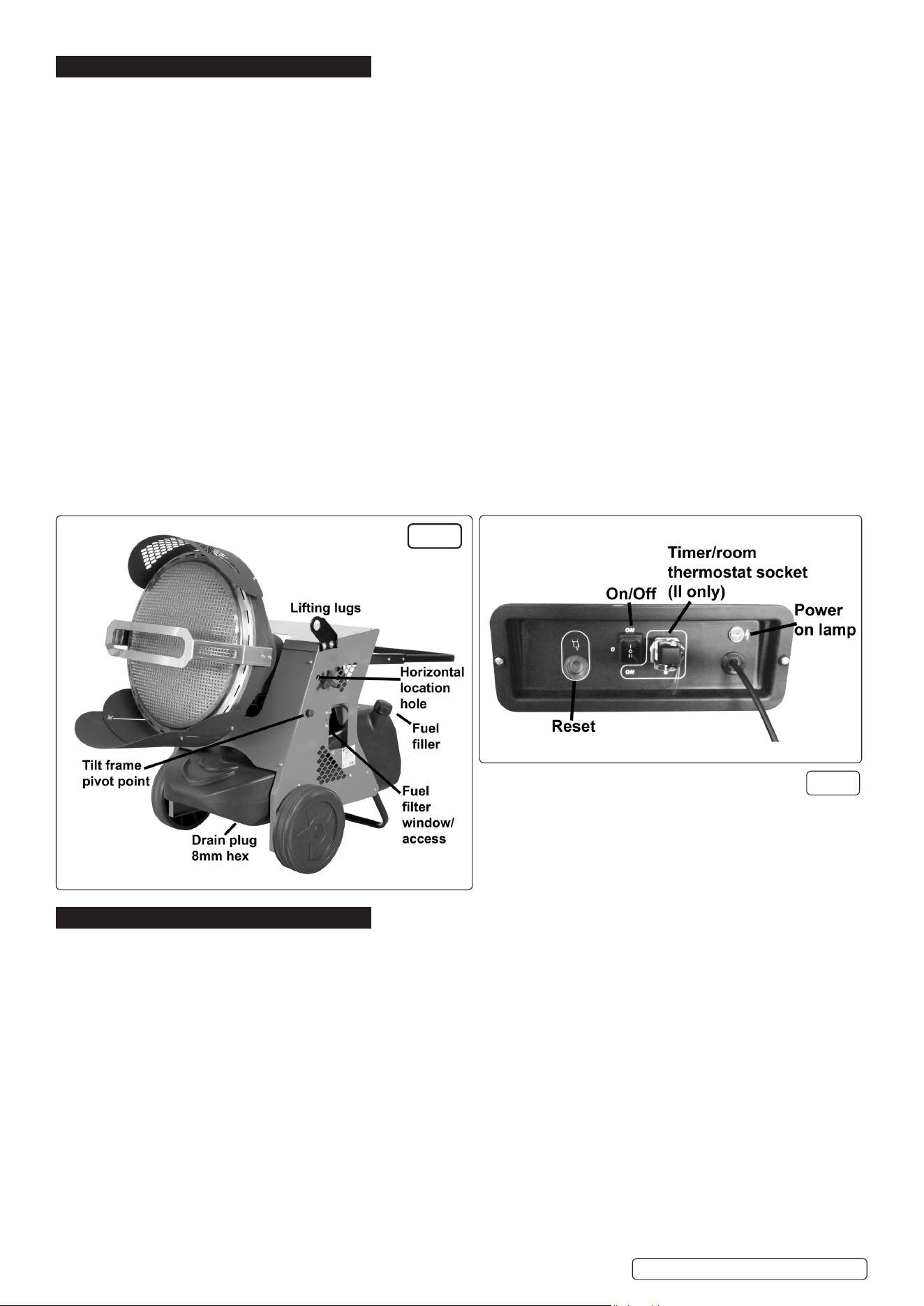
button will illuminate; wait two minutes before resetting. Repeat if necessary.
6.1.1. The drain plug is mid position beneath the tank and requires an 8mm hexagon key to operate. Ensure the plug is closed tight before
carefully lling the fuel tank with approved fuel through either ller neck. DO NOT ll or drain whilst the heater is operating.
6.1.2. Ensure both fuel caps are secure after lling.
6.1.3. Plug the power cord into a suitable power socket, indication of power will be shown by the power light illuminating in fig.2. If using an
extension lead see Section 1.1.
6.1.4. Set the selector switch to “I” (ON) and the heater will start. Select “O” to turn off; the heater ame will extinguish with the fan continuing
to run for approximately 90 seconds cooling the combustion chamber. Set the selector switch to “II” (ON) only when used in conjunction
with a timer or a room thermostat. If the heater ceases operating and goes into a misre sequence; set the selector switch to the “O”
position and immediately switch the selector switch to the desired function “I” or “II”.
NOTE: The automatic digital control system of this heater is protected by a fuse in the module. If the heater fails to re, check this fuse
rst, and replace if necessary. Also check the power source fuse and ensure that the correct voltage is being provided to the heater.
g.1
g.2
IR55.V2 | Issue:1 08/04/20
6.2. INCLINED FEATURE
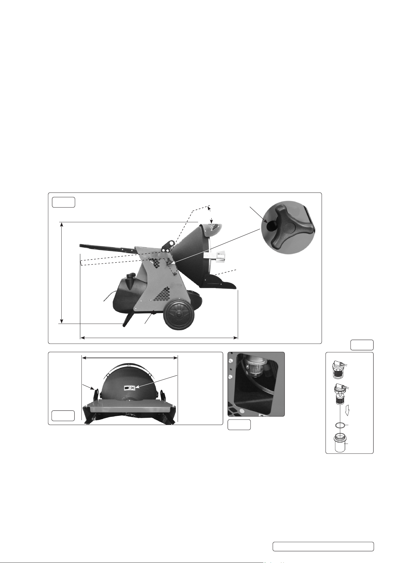
6.2.1. The ow of heat can be directed horizontally or inclined upward with an approximate 10° angle from the horizontal. Loosen the hand
screws (g.3) sufciently but not completely from the side panels of the heater, using the handle bar as a lever locate the shoulder of the
hand screws in the required hole position, and tighten the hand screws to secure. Utilise the lower adjustable deector as required, fully
extended when using horizontally to protect the oor for example.
6.3. TO STOP THE HEATER
6.3.1. Select “O” position on the control panel. Combustion will stop, and the ‘Cooling Cycle’ (approximately 90 seconds) will begin.
6.3.2. When the ‘Cooling Cycle’ is completed the fan stops running and it is safe to unplug the heater.
WARNING!Unpluggingtheheaterbeforethe‘CoolingCycle’hasnishedmaycauseoverheating,possibledamagetothe
heater and heat plate, and will void the warranty.
6.4. TO RESTART THE HEATER
6.4.1. Be sure to follow all starting procedure precautions.
6.4.2. Wait ten seconds after cooling cycle has completed.
6.4.3. Start heater by pressing “I” position on the selector switch, if required and linked to timer or thermostat choose “II” position. Select “O”
to stop.
6.5. TRANSPORTING
6.5.1. Before the heater is moved it must be stopped and unplugged from the mains.
6.5.2. The heater must be totally cooled off.
6.5.3. Ensure tank breather and ller caps are securely closed.
6.5.4. For transporting short distances on level surfaces the handlebar and wheels are adequate. For more arduous locations and distances,
lugs are tted for lifting with rope, slings or chains.
WARNING! During handling and transporting, oil may leak. The fuel and breather caps are not an absolute seal, enabling air
to enter and escape during operation. Never transport or service the heater while it is operating, while hot or plugged into the
mains. Severe burns or electric shock could occur.
Use only original equipment replacement parts. The use of alternate or third party components can cause unsafe operating conditions,
and will void the warranty. We suggest following a maintenance schedule as follows.
6.6. FUEL/FUEL TANK
6.6.1. Flush every 200 hours of operation or as needed. DO NOT use water to ush the tank. The drain plug position which is shown in
g.3 and g.5 requires an 8mm hexagon key to remove. It may be necessary to elevate the heater as ground clearance is small. After
draining into a suitable container for recycling replace plug and ush with a minimal amount of fresh kerosene/parafn/diesel only.
Drain again into the container for recycling. Clean drain plug, seal ring, seat and replace, tighten to seal.
6.7. FILTERS
The Fuel Filter and Oil Filter should be cleaned every 50 hours by rinsing them in clean kerosene/parafn/diesel. The fuel lter can be
viewed, accessed and removed through a cutout in the side panel (g.5).This procedure shown in g.6 should also be followed if the
fuel is found to be contaminated. Replace the lter if damaged or old.
Loosen the two hand screws
sufciently but not completely
Drain plug
10° Incline feature
Two holes joined
by smaller slot
Pivot
point
10°
1410mm
1055mm
g.3
g.5
g.6
g.4
Viewed from rear of burner
High temperature
warning label
Lifting lugs
715mm Over wheels
Rotate sight
glass to remove
Filter
"O" Ring
gasket
Sight glass
Strainer
IR55.V2 | Issue:1 08/04/20
Original Language Version
© Jack Sealey Limited
6.8. NOZZLE
6.8.1. The nozzle should be cleaned or replaced at least once per heating season. This procedure should also be followed if the fuel is found
to be contaminated.
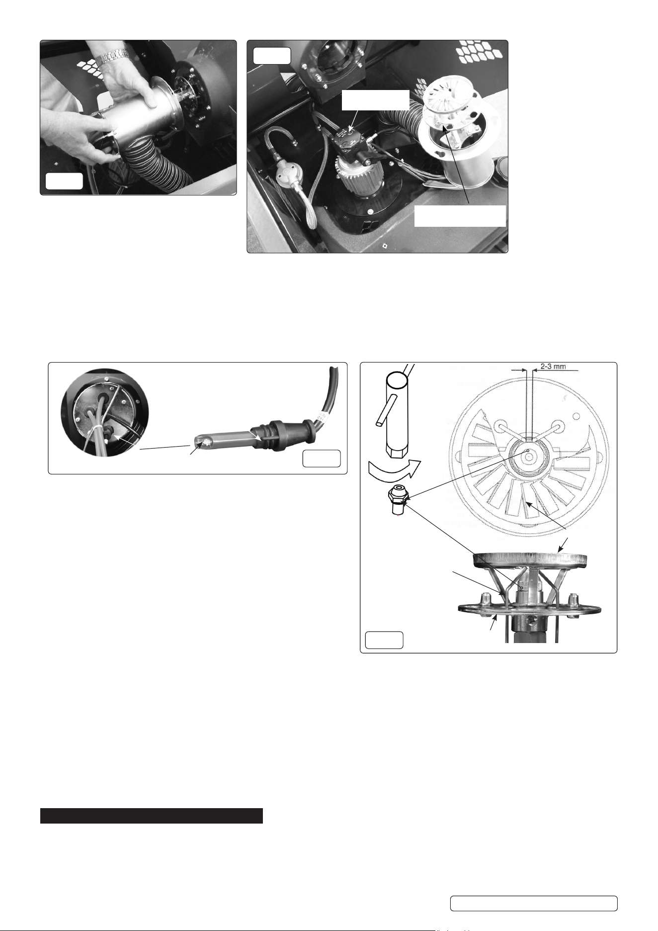
6.8.2. Remove the top cover and apron above fuel tank to access the blast tube area.
6.8.3. Remove the blast tube by unscrewing, not removing, the three hexagon headed machine screws through the ange. Unscrew
approximately 4mm from the keyhole slots.
6.8.4. Rotate the blast tube anticlockwise until the large hole in the slots aligns with the xings and remove/slide holding the tube
horizontally (g.7), nally resting the assembly as shown in g.8.
Note! Some internal parts are delicate and care is required in this process.
6.8.5. A 16mm A/F socket (g.10) will be required to remove the nozzle. It
will be necessary, with care to spring electrodes apart in removal.
8 DO NOT remove the top diffuser or damper disc.
6.8.6. To clean dirt from the nozzle, blow compressed air through nozzle
nose. It may be necessary to soak the nozzle in clean kerosene/
parafn/diesel to help loosen any particles (g.10).
6.8.7. Replacement of the nozzle and blast tube is the opposite of removal.
6.9. ELECTRODES
6.9.1. Clean and re-gap every 600 hours of operation (g.10), ensure
electrode gap is between 2-3mm and they do not touch other
components . To clean or replace the electrodes, the blast tube will
require partial removal as described in 6.8.2, 6.8.3 and 6.8.4.
6.9.2. Offer a long screwdriver through the damper disc hole and slot to
remove the cross head screw from the electrode tab.
6.9.3. “Unplug” locally the electrode from the high tension (HT) lead.
6.9.4. After removing the electrode, clean with a wire brush or replace.
6.10. PHOTOCELL
6.10.1. The Photocell should be cleaned at least once per heating season or more depending on conditions. It will be necessary to access the
blast tube by removing the apron above the fuel tank as in 6.8.2.
6.10.2. Remove by pulling straight against the small resistance offered.
6.10.3. Use a cotton swab dipped in water or alcohol to clean the lens of the Photocell (g.9).
6.10.4. Align tang with a slot in the insert bush and replace by pushing straight against the small resistance offered.
6.11. LONG TERM STORAGE
6.11.1. Unscrew the drain plug and drain fuel into a suitable container (g.1 and g.3) Using a small amount of kerosene/parafn/diesel, rinse
and swirl the fuel around the fuel tank. Empty the tank completely. (All as described in 6.6)
6.11.2. Neverstoreleftoverkerosene/parafn/dieseloverthesummer.Usingoldfuelcandamagetheheater.
6.11.3. Store heater in a dry, well ventilated area.
6.11.4. Be sure that the storage area is free of dust and corrosive vapours. Keep this User’s Manual in an easily accessible place.
7. FACTORY SETTING
7.1. DAMPER DISC (OR THROTTLE ADJUSTMENT)
The nozzle head sub assembly large disc is a close t inside the blast tube, hence directing and restricting (throttling) the air ow volume
from the fan through the slotted holes to the diffuser. The diffuser mixes the supplied air with the fuel to give the optimum burn
characteristics. This optimum setting for each burner is preset in the factory and this position is recorded and supplied with the heater
instructions. The entire sub assembly can be removed by loosening the cross head screw in the boss shown in g.10.
Factory set (P)Factory set (P)
DO NOTDO NOT adjust adjust
Factory set damperFactory set damper
discdisc DO NOT DO NOT adjust adjust
Loosen
Electrodes
Electrode gap
Damper throttle disc
Diffuser
Location tang
Lens
Blast tube rear
g.7
g.8
g.9
g.10
Original Language Version
© Jack Sealey Limited
IR55.V2 | Issue:1 08/04/20
Original Language Version
© Jack Sealey Limited
IR55.V2 | Issue:1 08/04/20
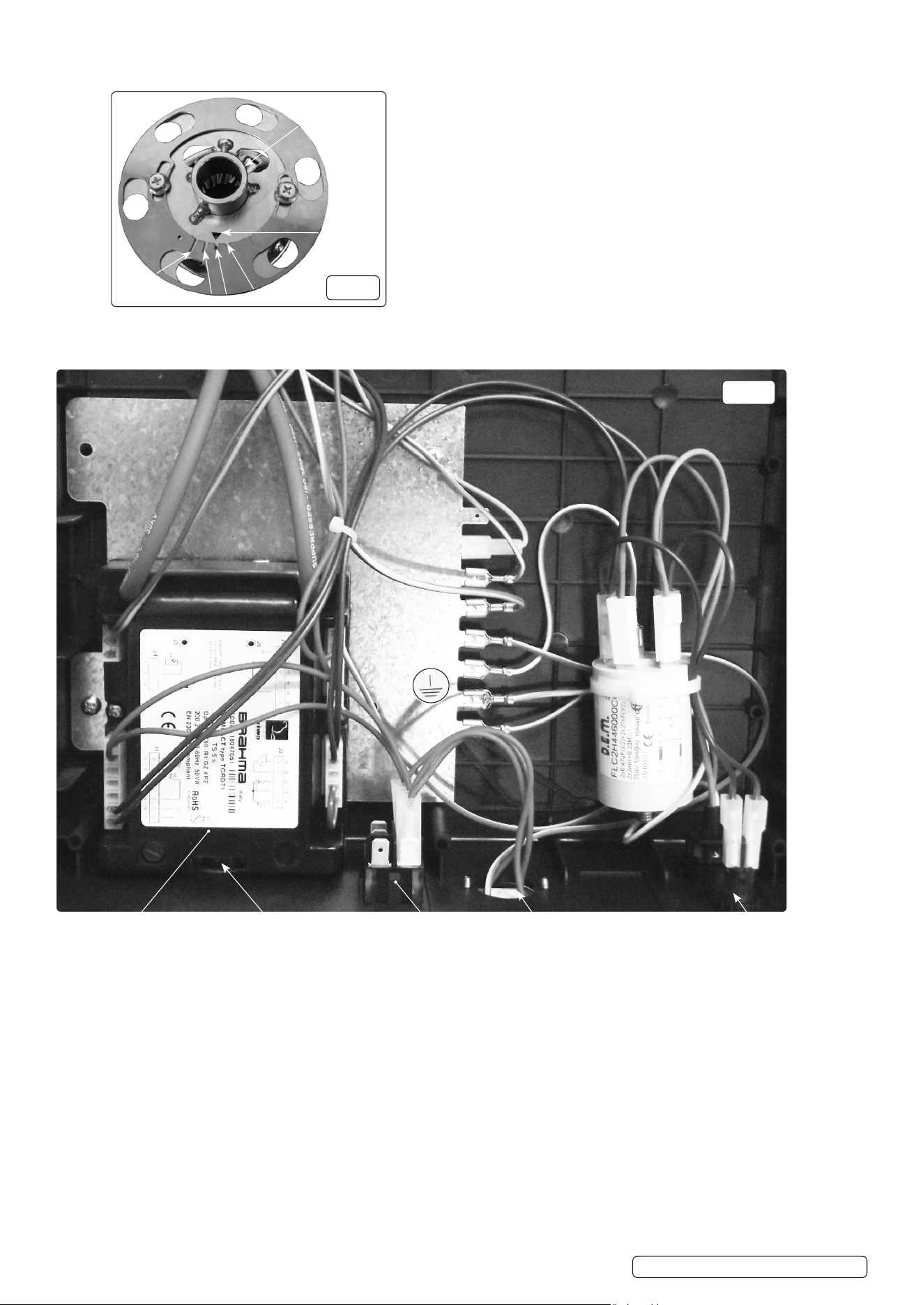
If removed for cleaning for example, make a note of the phasing notch (g.11) in the damper ring that aligns with the triangle apex
in the bossed ring. It must be reassembled with the same notch to triangle apex orientation.
EMC Filter
Automatic control
digital system.
Power on Lamp
Reset button
Room thermostat
or timer socket.
(Room thermostat or
timer not supplied)
"I"/"O"/"II"
Selector switch
4-Throttling damper disc phasing slots
[Setting 2]
Triangle
datum
Boss
1
2
4
3
g.11
g.12
Electrical hardware and wiring loom (see also g.4)
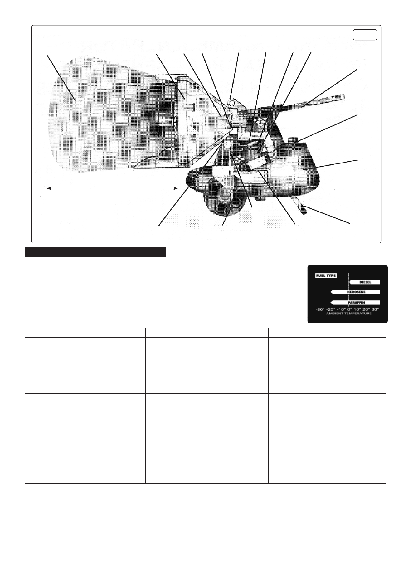
3000mm minimum clear of objects
Heat ow
Burner
Combustion
chamber
Nozzle
Lifting
eyes
Pump
Solenoid
valve
Motor
Handlebar
2 Filler/breather caps
Fuel tank
Stand
Fuel
lter
Wheels
Fuel
lines
Fan
Heater Sub Assemblies
g.13
8. TROUBLESHOOTING
Although this heater operates with diesel fuel, when the temperatures are below 0°C, diesel additives
are required to maintain the diesel’s viscosity. Typically diesel can cloud in freezing conditions and will
start to gel. You will need additives for your fuel in these conditions.
Kerosene/Parafn does not start to gel until the ambient temperature is around -40°C.
WARNING!
This heater is not suitable for use with Bio-Diesel; use of Bio-Diesel will damage the
lterandseals.DamagecausedbyuseofBio-Dieselwillnotbecoveredbywarranty. .
Problem Possible Cause Possible Solution
Motor does not start, no ignition. 1) No mains power.
2) Thermostat setting or other control setting
3) Thermostat or other control device
defective.
4) Electric motor defective.
5) Burned out condenser.
6) Improper electrical connection to the
automatic control digital system.
1) Check mains, check fuse.
2) Check settings and function of switches.
3) Replace.
4) Replace.
5) Replace condenser.
6) Check all wiring connections.
Motor starts, no ignition or the burner cuts out. 1) Electric igniter
2) Flame control from the automatic control
digital system.
3) Photocell defective.
4) Fuel delivery inadequate.
5) Moisture in fuel/fuel tank.
6) Nozzle blocked.
7) Solenoid valve defective.
1) Check HT leads, check electrode gap
and condition (g.12).
2) A non-serviceable item with expected
trouble free service of greater than
250,000 operations, contact your
Sealey stockist for spare part or testing.
3) Clean/replace (g.11)
4) Check motor pump coupling and fuel lter.
5) Rinse out fuel tank, and ll with clean fuel.
6) Clean or replace oil nozzle (g.12) see
section 6.3.
7) Check connections and thermostat
L/T.
Problem Possible Cause Possible Solution
Motor starts, heater emits smoke. 1) Lack of air to support combustion.
2) Too much air supporting combustion.
3) Fuel contaminated.
4) Air leaks in fuel lines.
5) Not enough fuel at burner.
6) Too much fuel at burner.
1) Ensure air inlets and outlets are free.
Check manufacturer's setting of
damper throttling disc. See 7.1 and
technical specications in section 2.
Clean burner discs and diffuser (g.12).
2) Check damper disc setting (g.13).
3) Drain fuel from tank, and ll with clean fuel.
Clean or replace oil lter
4) Check lter glass cup is sealed and all
pipe connections for integrity. See also
section 5.1 on initial starting.
5) Pump pressure is factory set and should
not be adjusted in normal circumstances.
Contact your Sealey stockist for advice.
Clean or replace nozzle.
6) Pump pressure is factory set and should
not be adjusted in normal circumstances.
Contact your Sealey stockist for advice.
Clean or replace nozzle.
Sealey Group, Kempson Way, Suffolk Business Park, Bury St Edmunds, Suffolk. IP32 7AR
01284 757500 01284 703534 sales@sealey.co.uk www.sealey.co.uk
ENVIRONMENT PROTECTION
Recycle unwanted materials instead of disposing of them as waste. All tools, accessories and packaging should be sorted, taken to
a recycling centre and disposed of in a manner which is compatible with the environment. When the product becomes completely
unserviceable and requires disposal, drain any fluids (if applicable) into approved containers and dispose of the product and fluids
according to local regulations.
WEEE REGULATIONS
Dispose of this product at the end of its working life in compliance with the EU Directive on Waste Electrical and Electronic Equipment
(WEEE). When the product is no longer required, it must be disposed of in an environmentally protective way. Contact your local solid
waste authority for recycling information.
Note: It is our policy to continually improve products and as such we reserve the right to alter data, specifications and component parts without prior
notice.
Important: No Liability is accepted for incorrect use of this product.
Warranty: Guarantee is 12 months from purchase date, proof of which is required for any claim.
Original Language Version
© Jack Sealey Limited
IR55.V2 | Issue:1 08/04/20