THIS INSTRUCTION BOOKLET CONTAINS IMPORTANT SAFETY INFORMATION. PLEASE READ AND KEEP FOR FUTURE REFERENCE.
EN
DE
FR
ES
IT
PL
With your inspiring rating, COSTWAY will be more consistent to offer you EASY
SHOPPING EXPERIENCE, GOOD PRODUCTS and EFFICIENT SERVICE!
Mit Ihrer inspirierenden Bewertung wird COSTWAY konsistenter sein, um Ihnen EIN
SCHÖNES EINKAUFSERLEBNIS, GUTE PRODUKTE und EFFIZIENTEN SERVICE zu
bieten!
Avec votre évaluation inspirante, COSTWAY continuera à fournir une EXPÉRIENCE
D’ACHAT PRATIQUE, des PRODUITS DE QUALITÉ et un SERVICE EFFICACE !
Con su calificación inspiradora, COSTWAY será más consistente para ofrecerle
EXPERIENCIA DE COMPRA FÁCIL, BUENOS PRODUCTOS y SERVICIO EFICIENTE.
Con la tua valutazione incoraggiante, COSTWAY sarà più coerente per offrirti
ESPERIENZA DI ACQUISTO FACILE, BUONI PRODOTTI e SERVIZIO EFFICIENTE!
Dzięki twojej opinii COSTWAY będzie mógł oferować jeszcze WYGODNIEJSZE
ZAKUPY, LEPSZE PRODUKTY i SPRAWNIEJSZĄ OBSŁUGĘ KLIENTA.
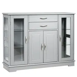
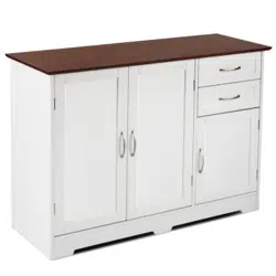
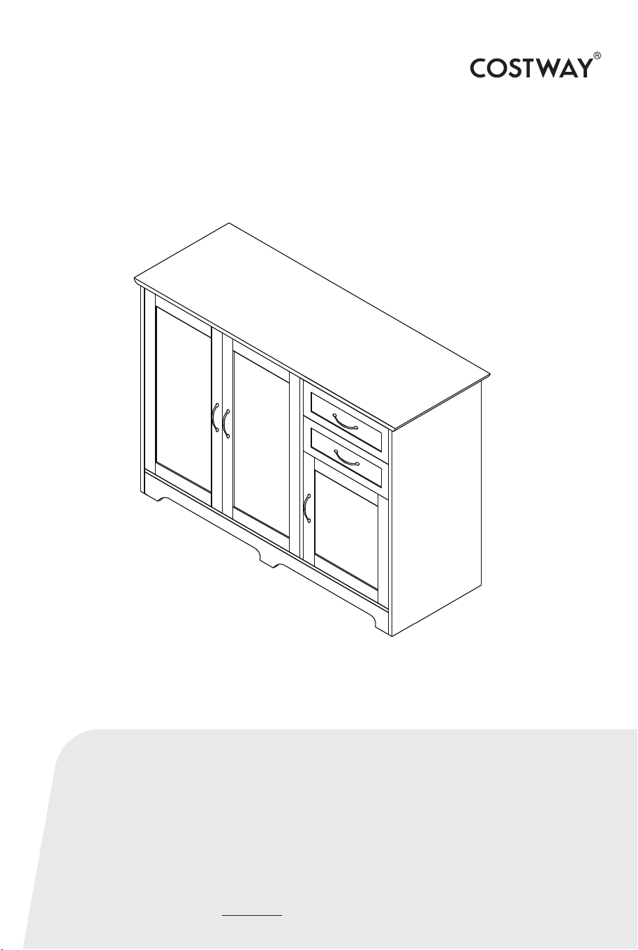
Storage Cabinet
USER’S MANUAL
US office: Fontana UK office: Ipswich AU office: Truganina
DE office: Hamburg
FR office: Saint Vigor d'Ymonville
PL office: Gdańsk
A
26 pcs
B
26 pcs
C
22 pcs
D
2 pcs
E
8 pcs
F
35 pcs
G
3 pcs
H
4 pcs
I
30 pcs
J
6 pcs
Hardware List
02 03
K
10 pcs
L
5 pcs
M
4 pcs
N
4 pcs
O
4 pcs
4*30mm
3*12mm
2.5*10mm
Cam-bolt
Cam-lock
Wood Dowel
Magnetic Catch
Screw
Screw
Magnetic Bar
3*14mmScrew
Screw
Hinge
P
2 pcs
4*14mmHandle Bolt
Handle
Plastic Glide
Stopper
Shelf Pin
4*40mmScrew
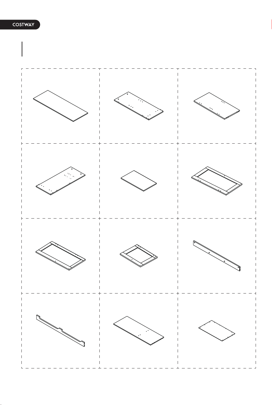
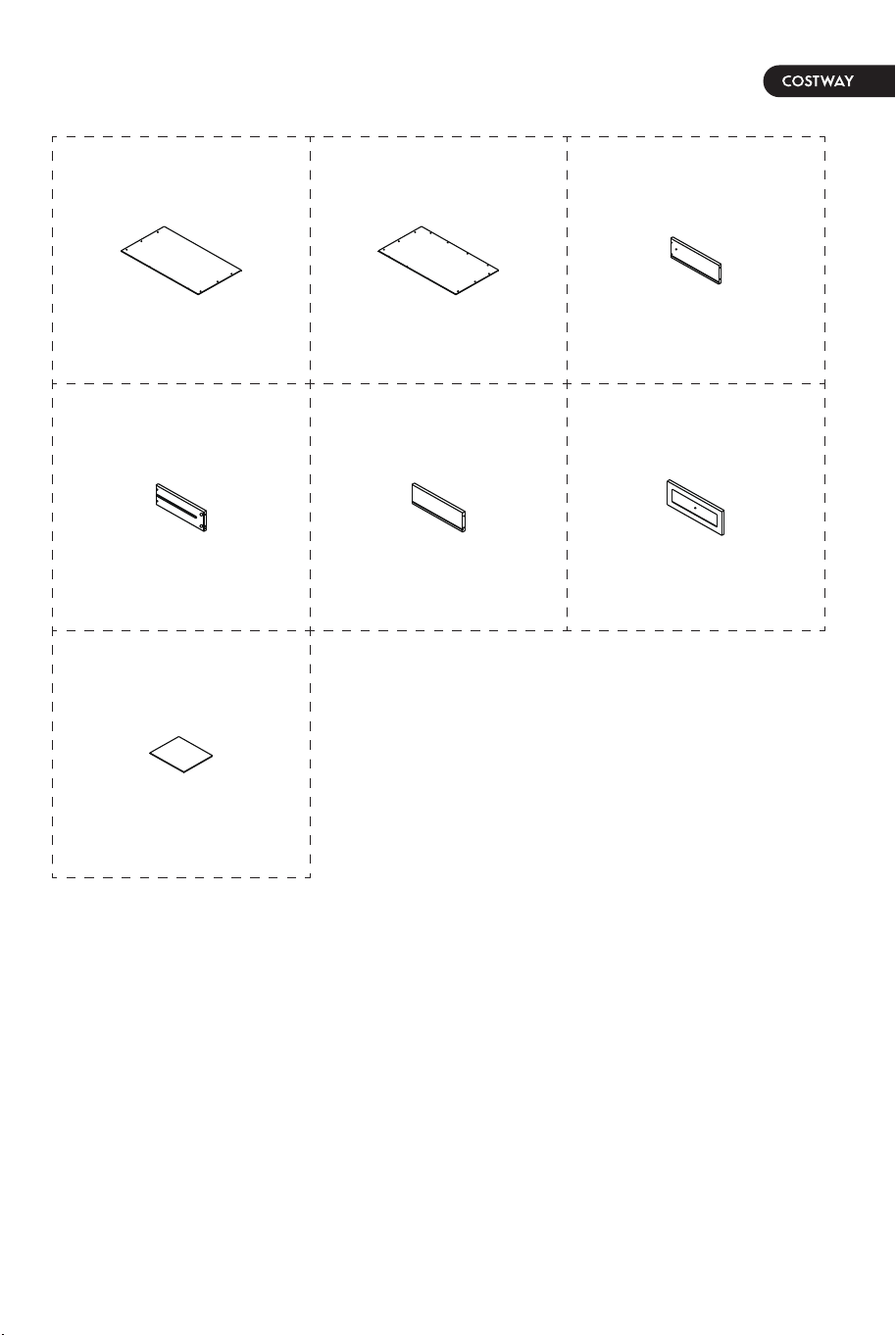
Parts List
04 05
1 pc
Top Panel Left Side Panel Divide Panel
1 1 pc2 1 pc3
1 pc4 1 pc5 1 pc6
1 pc7 1 pc8 1 pc9
1 pc13 1 pc14 2 pcs15
2 pcs16 2 pcs17 2 pcs18
2 pcs19
1 pc10 1 pc11 1 pc12
Right Side Panel Adjustable Shelf Left Door
Middle Door Right Door
Bottom Back
Connect+Bar
Bottom Front
Connect Bar Bottom Panel Left Back Panel
Middle Back Panel Right Back Panel Drawer Right Panel
Drawer Left Panel
Drawer Bottom Panel
Drawer Back Panel Drawer Front Panel
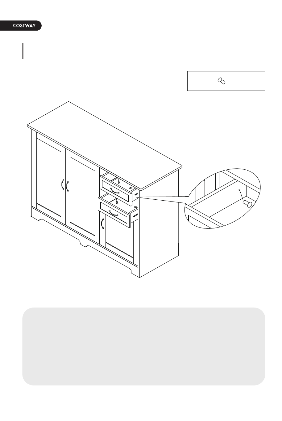
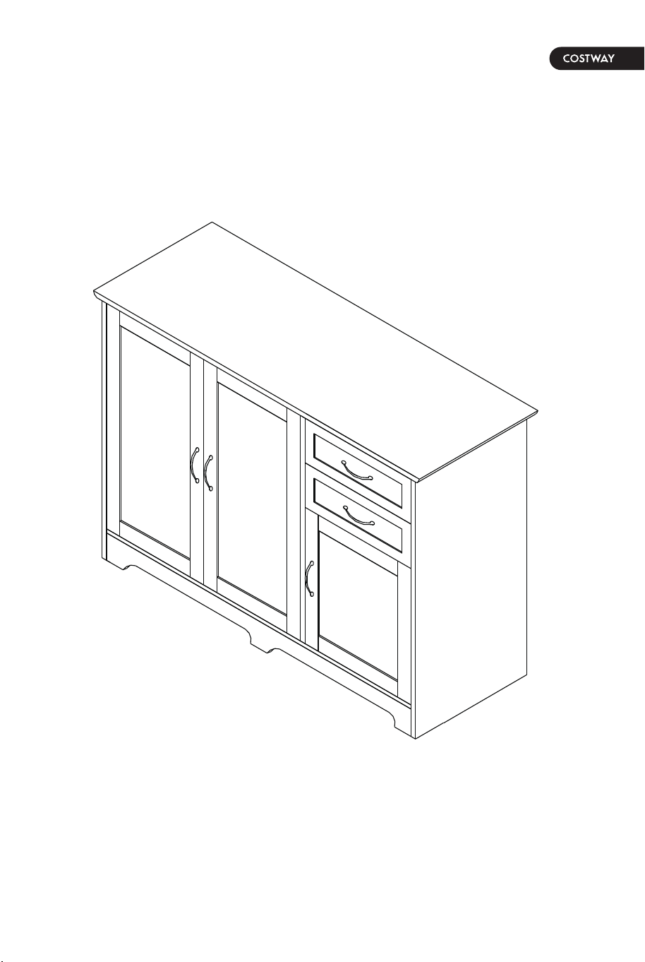
Part List Assembly Overview Step 1
06 07
1
2
3
4
5
6
7
8
9
10
12
11
13
14
15
16
17
18
15
16
17
18
19
19
x2
E
E
15
16
17
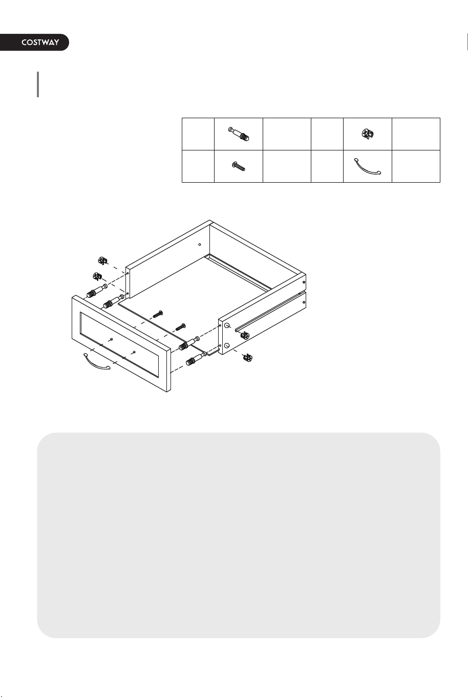
8 pcsE
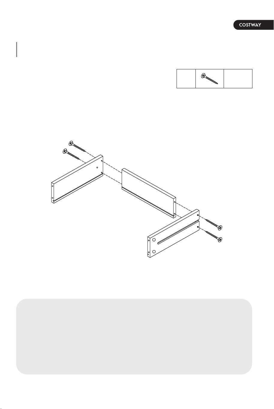
Attach Drawer Left & Right Panels (15 & 16) to Drawer Back Panel
(17) by using Screw (E) as shown. Do not Overtighten.
Note: the groove on each panel is at the bottom.
Part List Assembly Overview Step 1
06 07
1
2
3
4
5
6
7
8
9
10
12
11
13
14
15
16
17
18
15
16
17
18
19
19
x2
E
E
15
16
17
8 pcsE
Attach Drawer Left & Right Panels (15 & 16) to Drawer Back Panel
(17) by using Screw (E) as shown. Do not Overtighten.
Note: the groove on each panel is at the bottom.
Step 2 Step 3
08 09
8 pcsA 8 pcsB
2 pcsL4 pcsK
4 pcsA 4 pcsB
6 pcsC
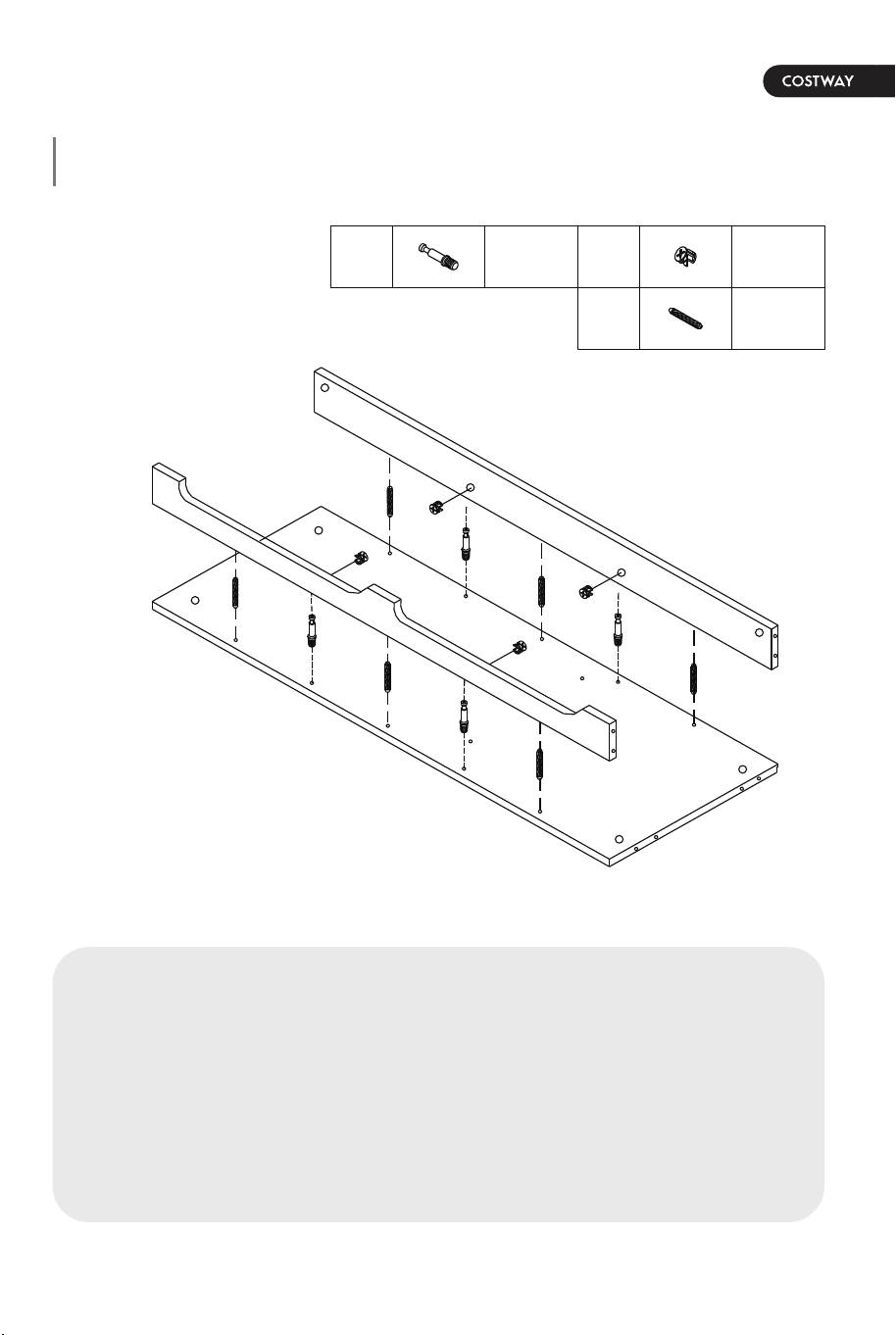
a) Screw In Cam-bolt (A) into designated holes on Drawer Front
Panel (18).
b) Fit Bottom Panel (19) to Drawer Panels (15, 16 & 17) via groove
on respective drawer panels.
c) Align Cam-bolts on (18) to the holes on Drawer Side Panels and
attach (18) firmly. Check that front edge of Bottom Panel (19) fit
into groove on the inside-face of respective Front Panel (18).
d) Insert Cam-Lock (B) to the designated holes on Drawer Side
Panels, then turn clockwise to lock onto Cam-bolt. Do not
overtighten.
e) Attach Handle (L) to (18) by using Handle Bolt (K).
a) Screw in Cam-bolt (A) into designated holes on Bottom Panel
(11).
b) Insert Wood Dowel (C) to the designated holes on Bottom Back
and Front Connect Bar (9 & 10).
c) Attach (9 & 10) to (11) via Cam-bolts and Wood Dowels.
d) Insert Cam-Lock (B) to the designated holes on (9 & 10), then
turn clockwise to lock onto Cam-bolt. Do not overtighten.
x2
L
19
18
A
B
K
A
B
C
9
10
11
Step 2 Step 3
08 09
8 pcsA 8 pcsB
2 pcsL4 pcsK
4 pcsA 4 pcsB
6 pcsC
a) Screw In Cam-bolt (A) into designated holes on Drawer Front
Panel (18).
b) Fit Bottom Panel (19) to Drawer Panels (15, 16 & 17) via groove
on respective drawer panels.
c) Align Cam-bolts on (18) to the holes on Drawer Side Panels and
attach (18) firmly. Check that front edge of Bottom Panel (19) fit
into groove on the inside-face of respective Front Panel (18).
d) Insert Cam-Lock (B) to the designated holes on Drawer Side
Panels, then turn clockwise to lock onto Cam-bolt. Do not
overtighten.
e) Attach Handle (L) to (18) by using Handle Bolt (K).
a) Screw in Cam-bolt (A) into designated holes on Bottom Panel
(11).
b) Insert Wood Dowel (C) to the designated holes on Bottom Back
and Front Connect Bar (9 & 10).
c) Attach (9 & 10) to (11) via Cam-bolts and Wood Dowels.
d) Insert Cam-Lock (B) to the designated holes on (9 & 10), then
turn clockwise to lock onto Cam-bolt. Do not overtighten.
x2
L
19
18
A
B
K
A
B
C
9
10
11
Step 4 Step 5
10 11
8 pcsF 4 pcsM
1 pcD2 pcsH
8 pcsA 8 pcsB
2 pcsP10 pcsC
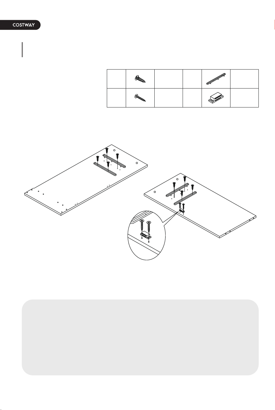
a) Attach Plastic Glide (M) to Divide Panel (3) and Right Side Panel
(4) by using Screw (F).
b) Attach Magnetic Catch (D) to Divide Panel (3) by using Screw (H).
a) Screw in Cam-bolt (A) to the designated holes on Side Panels (2
& 4).
b) Insert Wood Dowel (C) to the designated holes on (3, 9, 10 & 11)
as shown.
c) Attach Divide Panel (3) to Bottom Panel (11) via Wood Dowels,
then fix by using Screw (P). Do not overtighten.
d) Attach Side Panels (2 & 4) to (9, 10 & 11) via Cam-bolts and
Wood Dowels.
e) Insert Cam-Lock (B) to the designated holes on (9, 10 & 11),
then turn clockwise to lock onto Cam-bolt. Do not overtighten.
F
M
4
H
D
3
F
M
H
D
P
2
3
4
B
C
C
A
3*12mm
3*14mm
Step 4 Step 5
10 11
8 pcsF 4 pcsM
1 pcD2 pcsH
8 pcsA 8 pcsB
2 pcsP10 pcsC
a) Attach Plastic Glide (M) to Divide Panel (3) and Right Side Panel
(4) by using Screw (F).
b) Attach Magnetic Catch (D) to Divide Panel (3) by using Screw (H).
a) Screw in Cam-bolt (A) to the designated holes on Side Panels (2
& 4).
b) Insert Wood Dowel (C) to the designated holes on (3, 9, 10 & 11)
as shown.
c) Attach Divide Panel (3) to Bottom Panel (11) via Wood Dowels,
then fix by using Screw (P). Do not overtighten.
d) Attach Side Panels (2 & 4) to (9, 10 & 11) via Cam-bolts and
Wood Dowels.
e) Insert Cam-Lock (B) to the designated holes on (9, 10 & 11),
then turn clockwise to lock onto Cam-bolt. Do not overtighten.
F
M
4
H
D
3
F
M
H
D
P
2
3
4
B
C
C
A
3*12mm
3*14mm
Step 6 Step 7
12 13
6 pcsA 6 pcsB
2 pcsH1 pcD
6 pcsC 30 pcsI
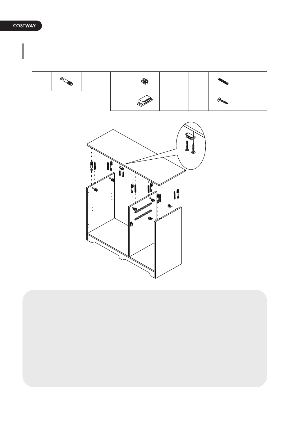
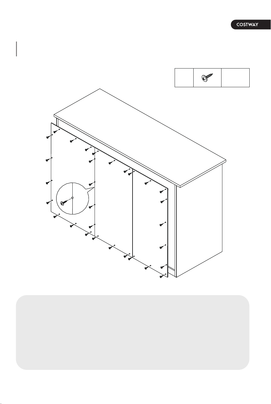
Attach Back Panel (12,13 & 14) by using Screw (I).
1
A
C
D
H
B
D
H
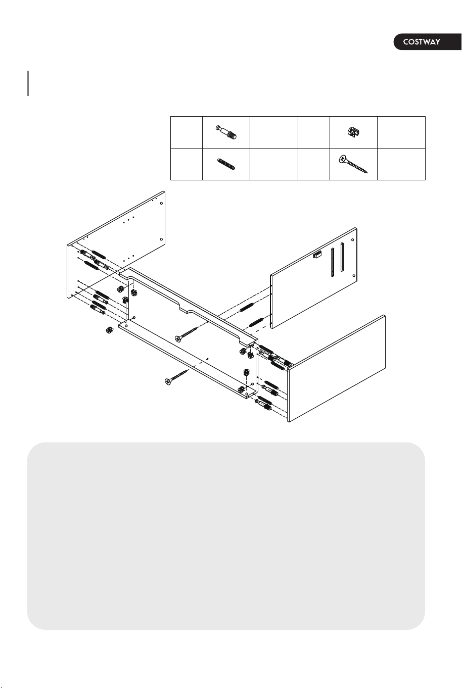
a) Screw in Cam-bolt (A) to the designated holes on Top Panel (1).
b) Attach Magnetic Catch (D) to Top Panel (1) by using Screw (H).
c) Insert Wood Dowel (C) to the designated holes on (2, 3 & 4) as
shown.
d) Attach Top Panel (1) to (2, 3 & 4) via Cam-bolts and Wood
Dowels.
e) Insert Cam-Lock (B) to the designated holes on (2, 3 & 4), then
turn clockwise to lock onto Cam-bolt. Do not overtighten.
I
14
13
12
14
13
I
3*14mm
Step 6 Step 7
12 13
6 pcsA 6 pcsB
2 pcsH1 pcD
6 pcsC 30 pcsI
Attach Back Panel (12,13 & 14) by using Screw (I).
1
A
C
D
H
B
D
H
a) Screw in Cam-bolt (A) to the designated holes on Top Panel (1).
b) Attach Magnetic Catch (D) to Top Panel (1) by using Screw (H).
c) Insert Wood Dowel (C) to the designated holes on (2, 3 & 4) as
shown.
d) Attach Top Panel (1) to (2, 3 & 4) via Cam-bolts and Wood
Dowels.
e) Insert Cam-Lock (B) to the designated holes on (2, 3 & 4), then
turn clockwise to lock onto Cam-bolt. Do not overtighten.
I
14
13
12
14
13
I
3*14mm
Step 8 Step 9
14 15
27 pcsF 3 pcsG
3 pcsL6 pcsK
6 pcsJ 4 pcsO
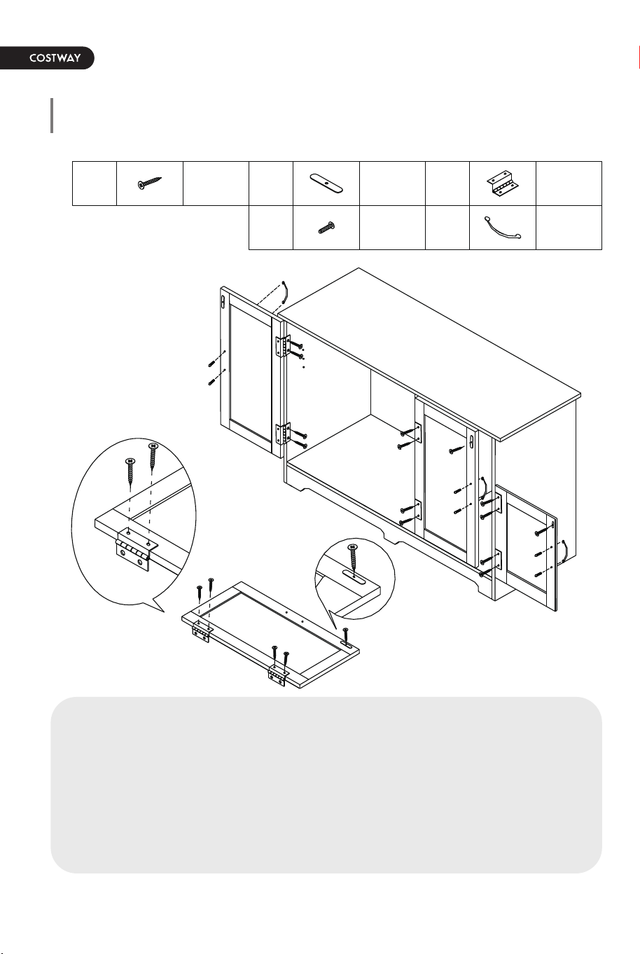
Insert Shelf Pin (O) and place Adjustable Shelf (5) on it.a) Attach Hinge (J) and Magnetic Bar (G) to Door (6, 7 & 8) by using
Screw (F) as shown.
b) Attach Door (6, 7 & 8) to cabinet by using Screw (F) as shown.
c) Attach Handle (L) to Doors (6, 7 & 8) by using Handle Bolt (K).
J
6
7
8
K
L
F
5
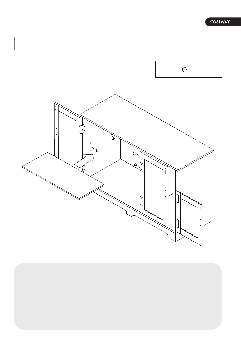
O
6
6
6
F
G
J
F
F
J
3*12mm
Step 8 Step 9
14 15
27 pcsF 3 pcsG
3 pcsL6 pcsK
6 pcsJ 4 pcsO
Insert Shelf Pin (O) and place Adjustable Shelf (5) on it.a) Attach Hinge (J) and Magnetic Bar (G) to Door (6, 7 & 8) by using
Screw (F) as shown.
b) Attach Door (6, 7 & 8) to cabinet by using Screw (F) as shown.
c) Attach Handle (L) to Doors (6, 7 & 8) by using Handle Bolt (K).
J
6
7
8
K
L
F
5
O
6
6
6
F
G
J
F
F
J
3*12mm
16 17
4 pcsN
Step 10
Insert drawers and Put Stopper (N) into the designated hole on
Drawer Side Panels.
The assembly of the Storage Cabinet unit is complete.
Important: Before inserting Stopper (N), check that the hole
does not pass the front end of Plastic Glide (M).
N
15
N
16 17
4 pcsN
Step 10
Insert drawers and Put Stopper (N) into the designated hole on
Drawer Side Panels.
The assembly of the Storage Cabinet unit is complete.
Important: Before inserting Stopper (N), check that the hole
does not pass the front end of Plastic Glide (M).
N
15
N

THIS INSTRUCTION BOOKLET CONTAINS IMPORTANT SAFETY INFORMATION. PLEASE READ AND KEEP FOR FUTURE REFERENCE.
EN
DE
FR
ES
IT
PL
With your inspiring rating, COSTWAY will be more consistent to offer you EASY
SHOPPING EXPERIENCE, GOOD PRODUCTS and EFFICIENT SERVICE!
Mit Ihrer inspirierenden Bewertung wird COSTWAY konsistenter sein, um Ihnen EIN
SCHÖNES EINKAUFSERLEBNIS, GUTE PRODUKTE und EFFIZIENTEN SERVICE zu
bieten!
Avec votre évaluation inspirante, COSTWAY continuera à fournir une EXPÉRIENCE
D’ACHAT PRATIQUE, des PRODUITS DE QUALITÉ et un SERVICE EFFICACE !
Con su calificación inspiradora, COSTWAY será más consistente para ofrecerle
EXPERIENCIA DE COMPRA FÁCIL, BUENOS PRODUCTOS y SERVICIO EFICIENTE.
Con la tua valutazione incoraggiante, COSTWAY sarà più coerente per offrirti
ESPERIENZA DI ACQUISTO FACILE, BUONI PRODOTTI e SERVIZIO EFFICIENTE!
Dzięki twojej opinii COSTWAY będzie mógł oferować jeszcze WYGODNIEJSZE
ZAKUPY, LEPSZE PRODUKTY i SPRAWNIEJSZĄ OBSŁUGĘ KLIENTA.
Storage Cabinet
USER’S MANUAL
US office: Fontana UK office: Ipswich AU office: Truganina
DE office: Hamburg
FR office: Saint Vigor d'Ymonville
PL office: Gdańsk