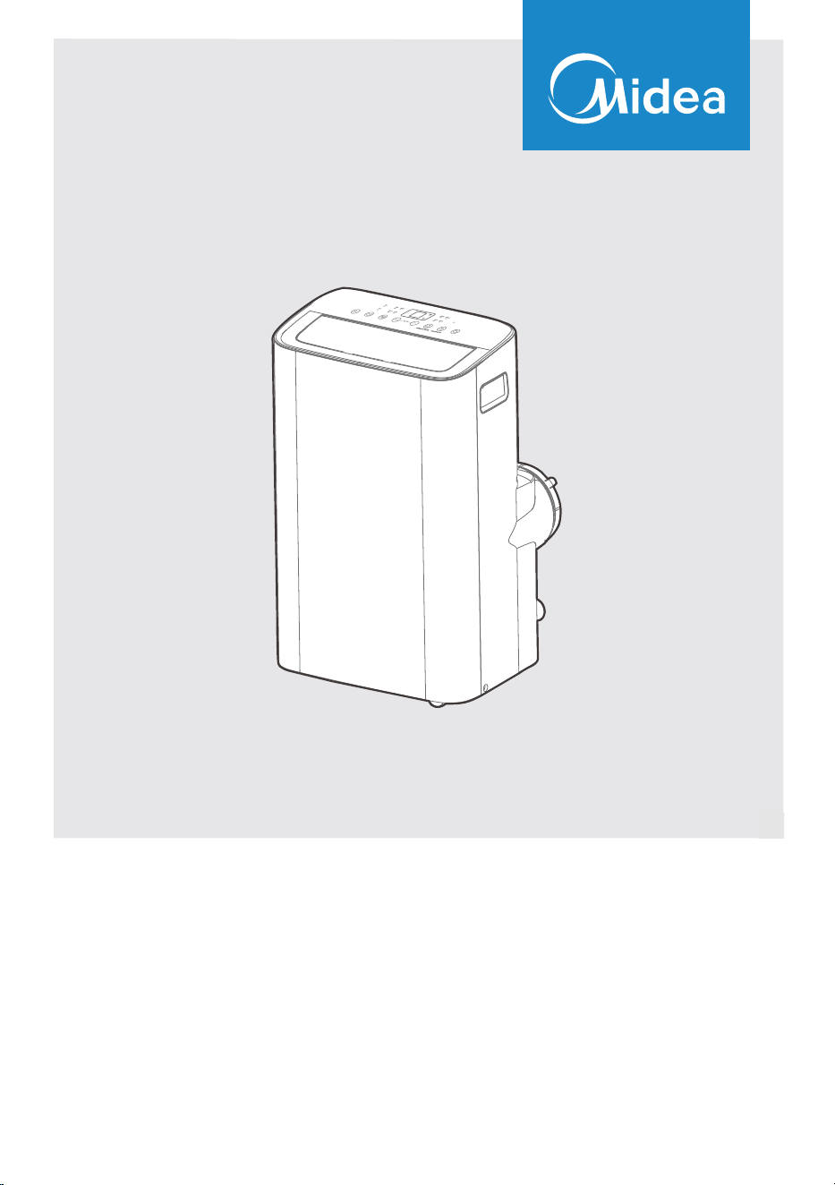
MAP08S1JWT-B
MAP10V1JWT-B
USER MANUAL
Before using this product, please read this manual carefully and keep it for future reference.
The design and specifications are subject to change without prior notice for product improvement. Consult
with your dealer or the manufacturer for details.
PORTABLE AIR CONDITIONER
2
CONTENTS
Read This Manual
Inside you’ll find many helpful hints on how to use and maintain your air conditioner
properly. Just a little preventative care on your part can save you a great deal of time
and money over the life of your air conditioner. You’ll find many answers to common
problems in the troubleshooting tips - you should be able to fix most of them quickly
before calling service. These instructions may not cover every possible condition
of
use, so common sense and attention to safety is required when installing, operating
and maintaining this product.
• For support, please call the Service Center at 1-866-646-4332.
• This appliance is not intended for use by people (including children) with reduced
physical, sensory or mental capabilities or lack of experience and knowledge, unless
they have been given supervision or instruction conce
rning use of the appliance by
a person responsible for their safety.
• Children should be supervised to ensure that they do not play with the air conditioner.
• The appliance shall be installed in accordance with national wiring regulations.
• Do not operate your air conditioner in a humid room such as a bathroom or laundry
room.
CAUTION
THANK YOU LETTER
Thank you for choosing Midea! Before using your new Midea product, please
read this manual thoroughly to ensure that you know how to operate the
THANK YOU LETTER.................................................................................................................2
SAFETY PRECAUTIONS...........................................................................................................3
BEFORE YOU GET STARTED.................................................................................................8
INSTALLATION INSTRUCTIONS..........................................................................................10
OPERATING INSTRUCTIONS.................................................................................................18
CLEANING & MAINTENANCE ...............................................................................................21
TROUBLESHOOTING TIPS......................................................................................................23
REMOTE CONTROL AND APP INSTRUCTIONS.............................................................24
3
WARNING
CAUTION
This symbol indicates a hazardous situation, which, if not avoided, could result
in minor or moderate injury.
This symbol indicates a hazardous situation which, if not avoided, could result
in death or serious injury.
This symbol addresses practices not related to physical injury.
SAFETY PRECAUTIONS
Must Read the Warning Message
Read Safety Precautions Before Operation and Installation.
To prevent property damage, injury or death to user or other people, the instructions in
this manual must be followed. Incorrect operation due to ignoring of instructions may
cause damage, harm, or death.
The level of risk is shown by the following indications.
NOTICE
• Installation must be performed according to the installation instructions. Improper
installation can cause water leakage, electrical shock, or fire.
• Use only the included accessories and parts, and specified tools for the installation.
Using nonstandard parts can cause water leakage, electrical shock, fire, and injury or
property damage.
• Make sure that the outlet you are using is grounded and has the appropriate voltage.
The power cord is equipped with a three-prong grounding plug to protect against
shock. Voltage information can be found on the nameplate of the unit.
• Your unit must be used in a properly grounded wall receptacle. If the wall receptacle
you intend to use is not adequately grounded or protected by a time delay fuse or
circuit breaker, have a qualified electrician install the proper receptacle (the fuse or
circuit breaker needed is determined by the maximum current of the unit. The
maximum current is indicated on the nameplate located on unit).
• Do not touch the unit with wet or damp hands or when barefoot.
• If the air conditioner is knocked over during use, turn off the unit and unplug it from
the main power supply immediately. Visually inspect the unit to ensure there is no
damage. If you suspect the unit has been damaged, contact a technician or customer
service for assistance.
• In a thunderstorm, the power must be cut off to avoid damage to the machine due to
lightning.
• Your air conditioner should be used in such a way that it is protected from moisture.
e.g. condensation, splashed water, etc. Do not place or store your air conditioner
where it can fall or be pulled into water or any other liquid. Unplug immediately if it
occurs.
• Install the unit on a flat, sturdy surface. Failure to do so could result in damage or
excessive noise and vibration.
WARNING

4
• The unit must be kept free from obstruction to ensure proper function and to
mitigate safety hazards.
• Do not modify the length of the power cord or use an extension cord to power the unit.
• Do not share a single outlet with other electrical appliances. Improper power supply
can cause fire or electrical shock.
• Do not install your air conditioner in a wet room such as a bathroom or laundry room.
Too much exposure to water can cause electrical components to short circuit.
• Do not install the unit in a location that may be exposed to combustible gas, as this
could cause fire.
• The unit has wheels to facilitate moving. Make sure not to use the wheels on thick
carpet or to roll over objects, as this could cause the unit to tip over.
• Do not operate a unit that has been dropped or damaged.
• Ensure the unit remains at least 3ft (1m) away from any combustible materials such as
bedding, curtains, and furniture.
• All wiring must be performed strictly in accordance with the wiring diagram located
inside of the unit.
• The unit’s circuit board (PCB) is designed with a fuse to provide overcurrent
protection. The specifications of the fuse are printed on the circuit board, such as:
T 3.15A/250V, etc.
• When the water drainage function is not in use, keep the upper and lower drain plug
firmly attached. When the drain plug is not in use, keep it out of reach of children to
avoid a choking hazard.
• This appliance is not intended for use by persons (including children) with reduced
physical, sensory or mental capabilities or lack of experience and knowledge, unless
they have been given supervision or instruction concerning use of the appliance by a
person responsible for their safety.
• Children should be supervised to ensure that they do not play with the appliance.
Children must be supervised around the unit at all times.
• If the supply cord is damaged, it must be replaced by the manufacturer, its service
agent or similarly qualified persons in order to avoid a hazard.
• Do not use this product for functions other than those described in this instruction
manual.
• Before cleaning, turn off the power and unplug the unit.
• Disconnect the power if strange sounds, smell, or smoke comes from it.
• Do not press the buttons on the control panel with anything other than your fingers.
• Do not remove any fixed covers. Never use this appliance if it is not working properly,
or if it has been dropped or damaged.
WARNING
CAUTION

5
• Do not operate or stop the unit by inserting or pulling out the power cord plug.
• Do not use hazardous chemicals to clean or come into contact with the unit. Do not
use the unit in the presence of inflammable substances or vapour such as alcohol,
insecticides, petrol, etc.
• Prior to cleaning or other maintenance, the appliance must be disconnected from the
supply mains.
• Do not remove any fixed covers. Never use this appliance if it is not working properly,
or if it has been dropped or damaged.
• Do not run cord under carpeting. Do not cover cord with throw rugs, runners, or
similar coverings. Do not route cord under furniture or appliances. Arrange cord away
from traffic area and where it will not be tripped over.
• Do not operate unit with a damaged cord, plug, power fuse or circuit breaker. Discard
unit or return to an authorized service facility for examination and/or repair.
• To reduce the risk of fire or electric shock, do not use this fan with any solid-state
speed control device.
• The appliance shall be installed in accordance with national wiring regulations.
• Contact the authorized service technician for repair or maintenance of this unit.
• Contact the authorized installer for installation of this unit.
• Do not cover or obstruct the inlet or outlet grilles.
• Always transport your air conditioner in a vertical position and stand on a stable, level
surface during use.
• Always contact a qualified person to carry out repairs. If the damaged power supply
cord must be replaced, use a new power supply cord obtained from the product
manufacturer. Do not repair the damaged cord.
• Hold the plug by the head of the power plug when taking it out.
• Turn off the product when not in use.
CAUTION
6
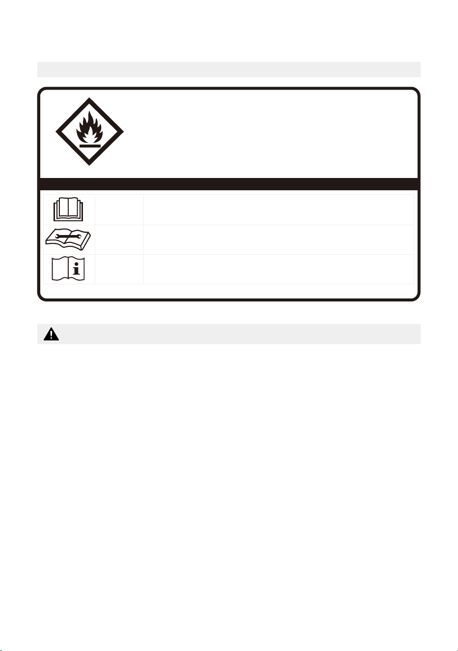
FOR R32 REFRIGERANT MODEL
CAUTION:
Risk of fire
flammable materials
IMPORTANT NOTE: Read this manual
carefully before installing or operating
your new appliance. Make sure to save
this manual for future reference.
Explanation of symbols displayed on the unit
CAUTION
This symbol shows that the operation manual should be read carefully.
CAUTION
This symbol shows that a service personnel should be handling this equipment with
reference to the installation manual.
CAUTION
This symbol shows that information is available such as the operating manual or
installation manual.
A2L
• Servicing shall only be performed as recommended by the equipment manufacturer.
Maintenance and repair requiring the assistance of other skilled personnel shall be
carried out under the supervision of a person competent in the use of flammable
refrigerants.
• DO NOT modify the length of the power cord or use an extension cord to power the
unit.
• DO NOT share a single outlet with other electrical appliances. Improper power
supply can cause fire or electrical shock.
• Please follow the instruction carefully to handle, install, clean, and service the
appliance to avoid any damage or hazard.
• When maintaining or disposing of the appliance, the refrigerant (R32) shall be
recovered properly and shall not discharge to air directly.
• Compliance with national gas regulations shall be observed.
• Keep ventilation openings clear of obstruction.
• The appliance shall be stored so as to prevent mechanical damage from occurring.
• A warning that the appliance shall be stored in a well-ventilated area where the
room size corresponds to the room area as specified for operation.
Flammable
Refrigerant R32 is used within appliance.
WARNING

7
• Any person who is involved with working on or breaking into a refrigerant circuit
should hold a current valid certificate from an industry-accredited assessment
authority, which authorizes their competence to handle refrigerants safely in
accordance with an industry recognized assessment specification.
Examples for such working procedures are:
• Breaking into the refrigerating circuit;
• Opening of sealed components;
• Opening of ventilated enclosures.
• No open fire or device like switch which may generate spark/arcing shall be around
the appliance to avoid causing ignition of the flammable refrigerant used. Please
follow the instruction carefully to store or maintain the appliance to prevent
mechanical damage from occurring.
• Do not use means to accelerate the defrosting process or to clean, other than those
recommended by the manufacturer.
• The appliance shall be stored in a room without continuously operating ignition
sources (for example: open flames, an operating gas appliance) and ignition
sources or (for example: an operating electric heater) close to the appliance.
• Do not pierce or burn.
• Be aware that the refrigerants may not contain an odor.
WARNING

8
BEFORE YOU GET STARTED
Energy Rating Information
The energy rating and noise information for this unit is based on the standard installation
using an un-extended exhaust duct without window slider adaptor (as shown in the
Installation section of this manual). With the unit operating on COOL MODE and HIGH
FAN SPEED.
The installation
must be carried
out in strict
accordance with
the instructions
in this manual.
We recommend
doing this with
a helper.
Installing
your AC
should take
about
30 minutes.
We’re here if
you need us,
please contact
1-866-646-4332
Preparations Before Installation
Manual
Temperature RangeMode
16~35°C (60~95°F)Cool
13~35°C (55~95°F)Dry
Ambient Temperature Range For Unit Operating:
Know your Portable Air Conditioner
How to Stay Cool with a New Portable Air Conditioner (For the models comply with the
requirements of Department Of Energy in US)
Because of a new federal test procedure for Portable Air Conditioners, you may notice
that the cooling capacity claims on portable air conditioner packaging are significantly
lower than that of models produced prior to 2017. This is due to changes in the test
procedure, not to the portable air conditioners themselves.

9
What Should I Look For First When Purchasing A Portable Air Conditioner?
The right air conditioner helps you cool a room efficiently. An undersized unit won’t cool
adequately while one that’s too large will not remove enough humidity, leaving the air
feeling damp. To find the proper air conditioner, determine the square footage of the
room you want to cool by multiplying the room length by its width. You also need to
know the air conditioner’s BTU (British Thermal Unit) rating, which indicates the amount
of heat it can remove from a room. A higher number means more cooling power for a
larger room. (Be sure you are comparing only newer models to each other. Older models
may appear to have a higher capacity, but are actually the same). Be sure to “size up” if
your portable air conditioner will be placed in a very sunny room, in a kitchen, or in a room
with high ceilings. After you’ve found the right cooling capacity for your room, you can
look at other features.
Why Newer Products Have Lower Cooling Capacity Than Older Models
Federal regulations require manufacturers to calculate cooling capacity based on a specific
test procedure, which was changed just this year. Models manufactured before 2017 were
tested under a different procedure and cooling capacity was measured differently in prior
year’s models. So, while the BTUs may be lower now, the actual cooling capacity of the air
conditioners has not changed.
What is SACC?
SACC is the representative value of Seasonally Adjusted Cooling Capacity, in Btu/h, as
determined in accordance with the DOE test procedure at title 10 Code of Federal
Regulations (CFR) 430, subpart B, appendix CC and applicable sampling plans.
10
INSTALLATION INSTRUCTIONS
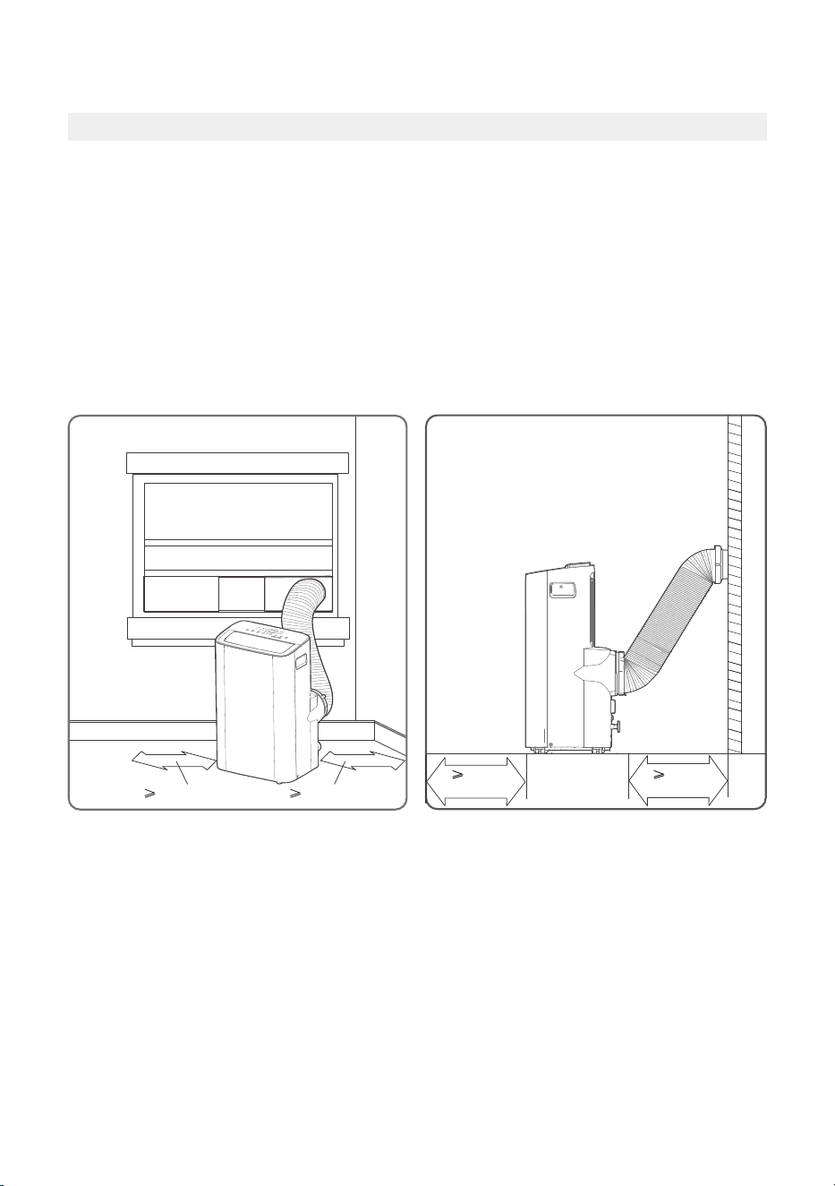
Product Installation Location
Your Installation Location Should Meet The Following Requirements:
• Make sure that you install your unit on an even surface to minimize noise and vibration.
• The unit must be installed near a grounded plug, and the Collection Tray Drain (found
on the back of the unit) must be accessible.
• The unit should be located at least 30cm (12”) from the nearest wall to ensure proper
air conditioning. The air outlet of the unit should be at least 50cm (19.7”) away from
obstacles.
• DO NOT cover the Intakes, Outlets or Remote Signal Receptor of the unit, as this could
cause damage to the unit.
Unit Installation Location Restricted Space Requirements
≥30cm (12”)
(19.7”)
≥
50cm
(19.7”)
≥30cm (12”)
≥
50cm
11
Product Overview
DESIGN NOTICE
In order to ensure the optimal performance of our products, the design specifications
of the unit and remote control are subject to change without prior notice.
NOTICE
All the illustrations in the manual are for explanation purpose only. Your machine may
be slightly different. The actual shape shall will remain the same.
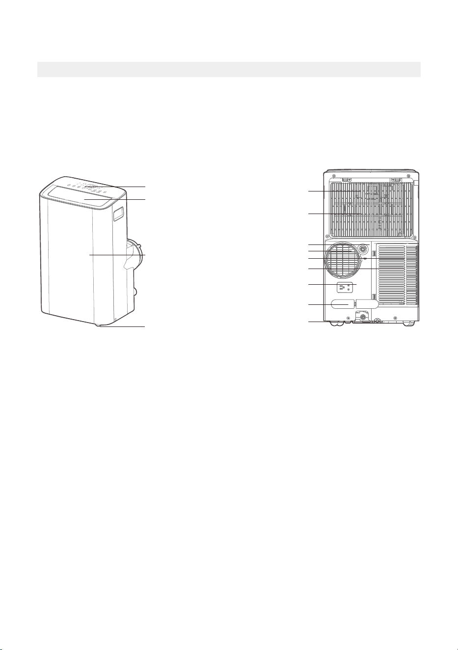
The unit can be controlled by the unit control panel alone or with the remote control.
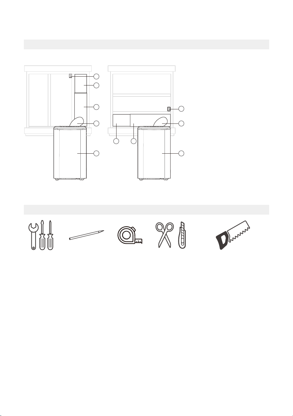
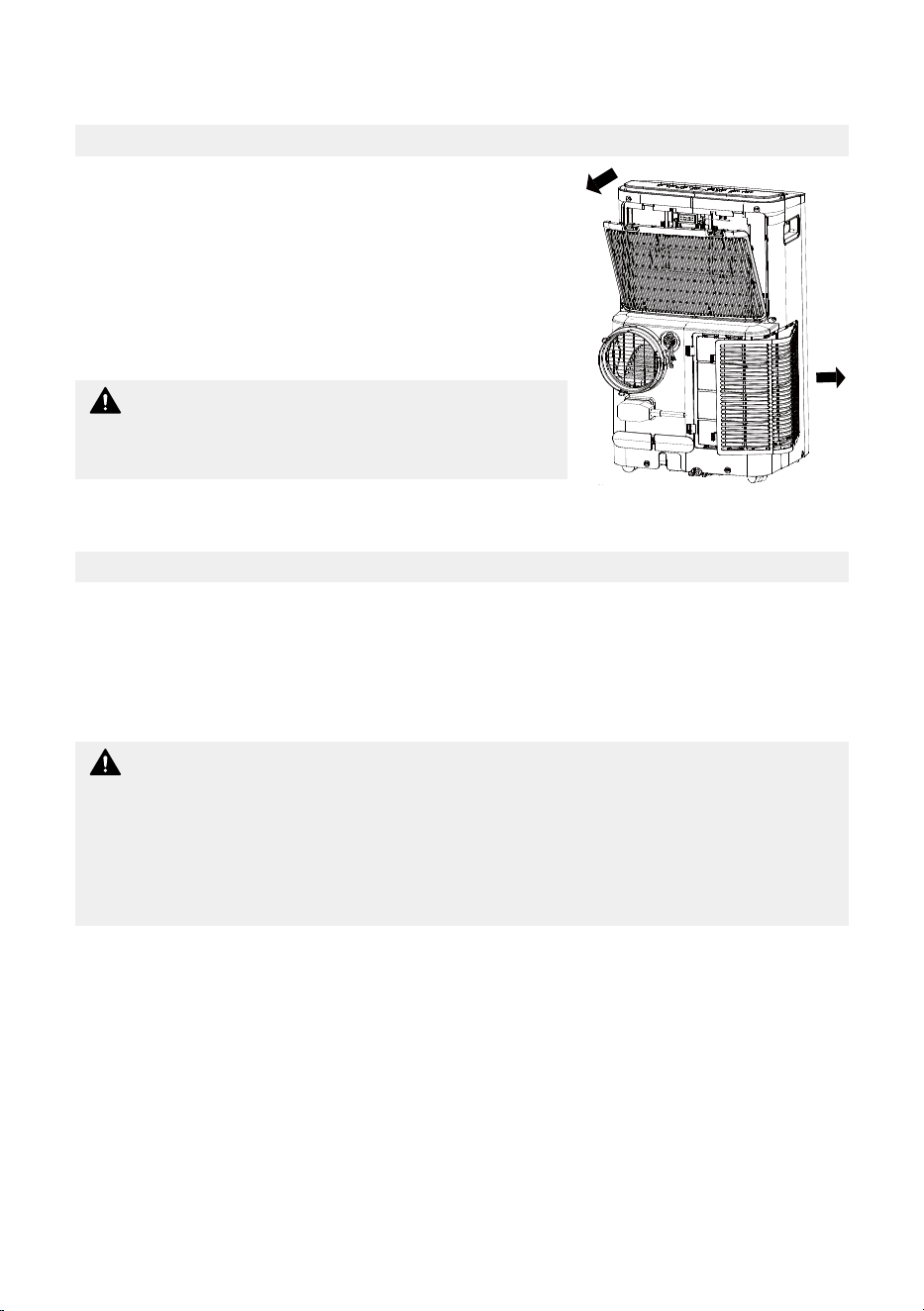
Front View Rear View
Drain outlet
Caster
Horizontal louver blade
(swing automatically)
Control panel
Front panel
Power plug socket
Power cord buckle
Bottom tray
drain outlet
Upper air filter
(behind the grille)
Upper air intake
Lower air filter
Lower air intake
Air outlet
12
Installation Overview
NOTICE
Illustrations in this manual
are for explanatory purposes.
The actual shape of your
indoor unit may be slightly
different. The actual shape
shall prevail.
Sliding Window Installation Hung Window Installation
1
4
1
2
2
1 1
4
3
3
1. Window Slider
2. Extended Exhaust Hose
3. Portable Air Conditioner
4. Security Bracket and
2 Screws
Installation Completion Display
Tools Needed
Screwdriver
& wrench
A tape
measure
Scissors
or Knife
Pencil Saw (On some models,
to shorten window adaptor
for narrow windows)
13
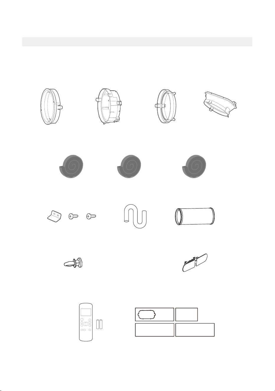
Installation Accessories
NOTICE
Items with (*) are on some models. Slight variations in design may occur.
Your Window Installation Kit fits windows 19.4”-62.2”(49.3-158.1cm) and can be shortened
for smaller windows.
Remote Controller
and Battery
(1 set*)
Bolt (3 pc)
Security Bracket
and 2 Screws (1 set)
(1 pc)
Exhaust Hose
Drain Hose
(1 pc)
Window Slider
Adaptor (*)
( 1 pc)
Foam Seal A
(Adhesive) 4 pc(*)
Foam Seal B
(Adhesive) 2 pc
Foam Seal C
(Non-adhesive) 2 pc(*)
Exhaust Hose
Adaptor
(1 pc*)
Power Cord
Buckle ( 1 pc)
Air exhaust
passage (1 pc*)
(1pc)
Unit Adaptor
Window Sliders
1 set(*)
14
For Optimal Performance In Operation
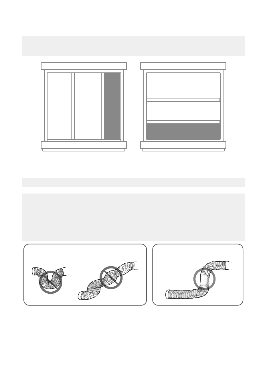
Confirm Your Window Type (Window Type And Opening Size Of
Different Types)
Sliding Window Installation Hung Window Installation
NOTICE
To ensure proper function, DO NOT overextend or bend the hose. Make sure that there
is no obstacle around the air outlet of the exhaust hose (in the range of 500mm) in
order to ensure the exhaust system works properly. All the illustrations in this manual
are for explanation purpose only. Your air conditioner may be slightly different. The
actual shape shall prevail.
CORRECTINCORRECT
15
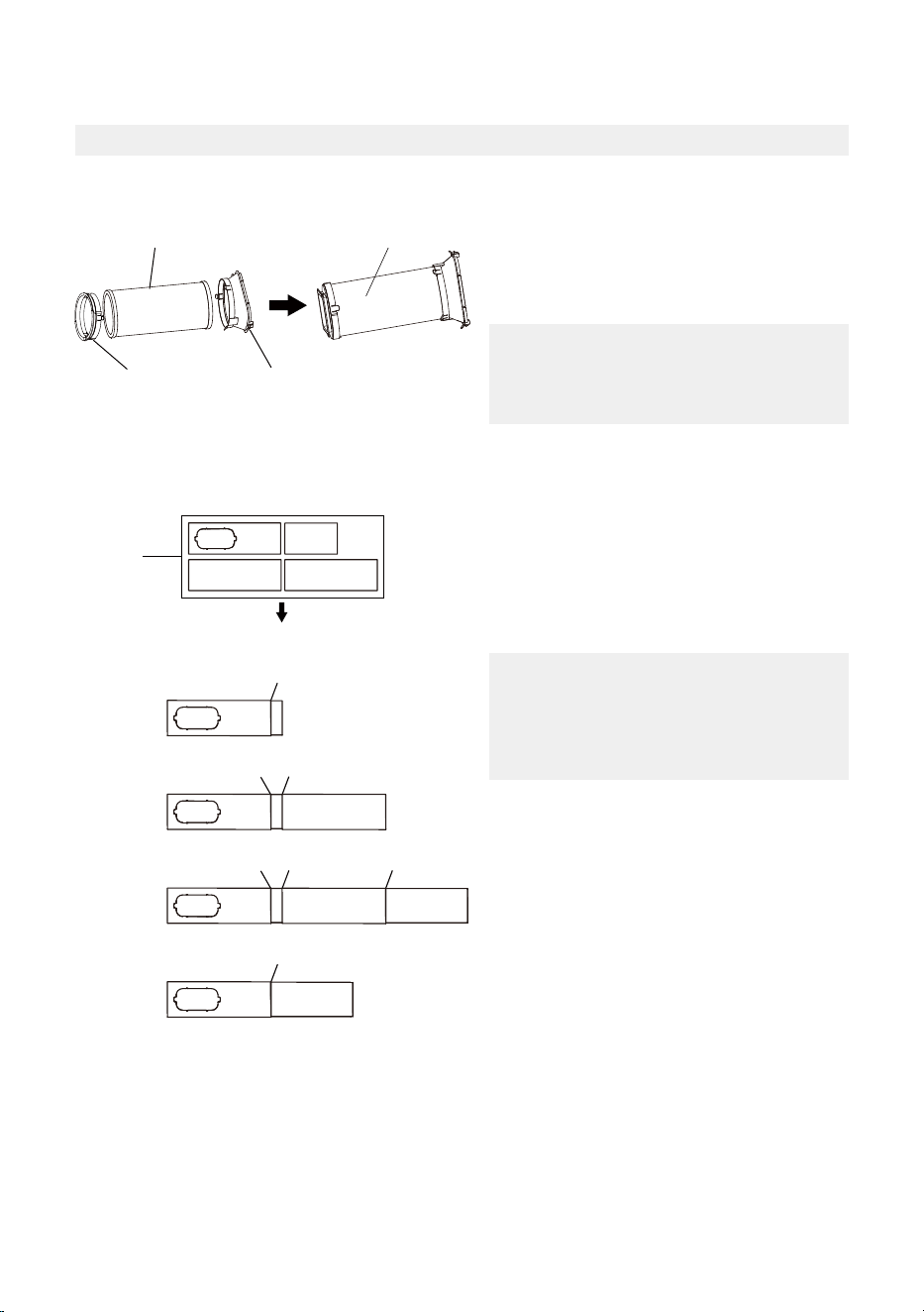
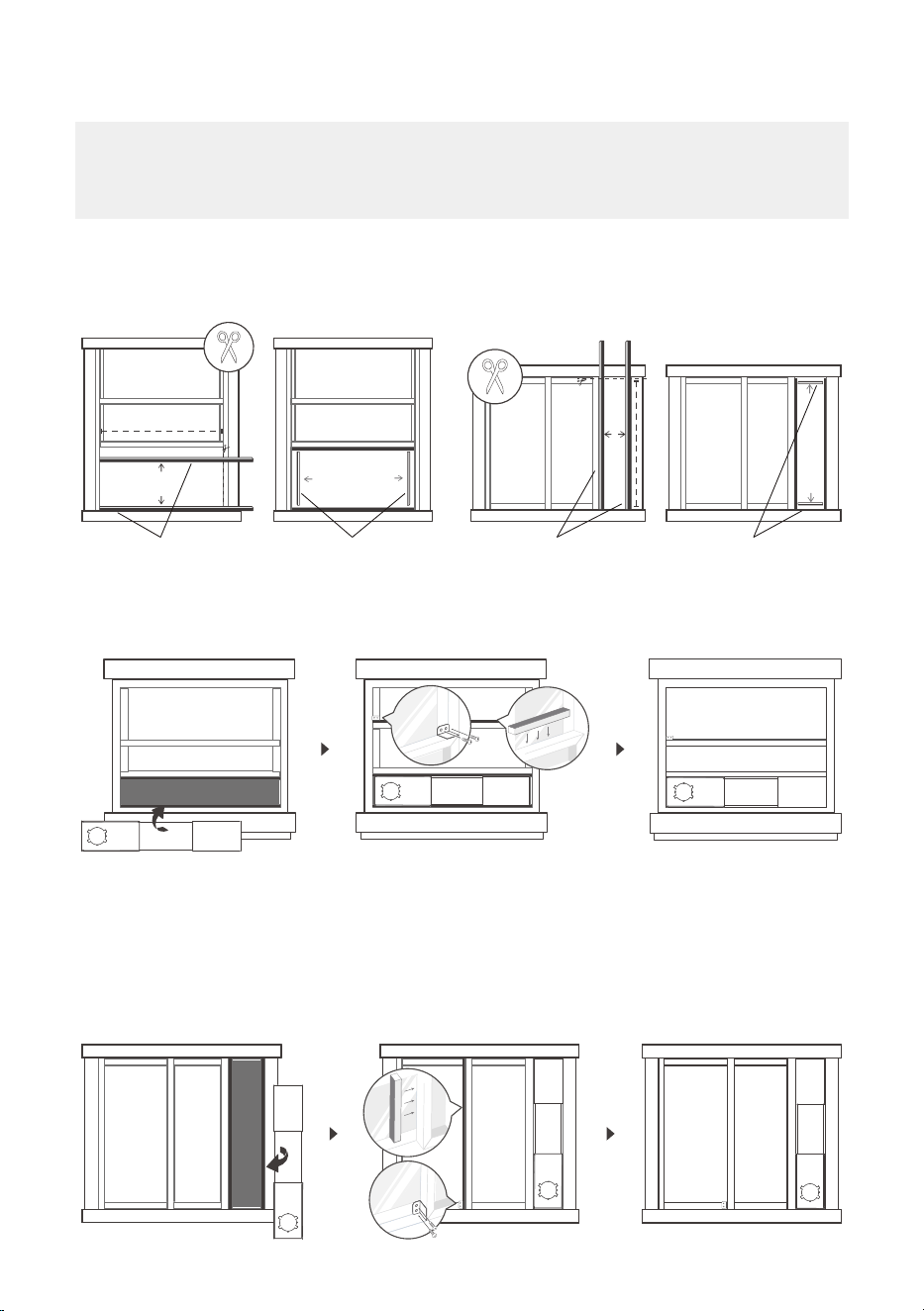
Exhaust Hose And Adaptors Installation
1 - The Exhaust Hose Assembly Installation (Window Type):
2 - Preparing the Adjustable Window Slider:
Exhaust hose
assembly
Exhaust hose
Unit adaptor
Air exhaust
passage
Press the exhaust hose (or extended
exhaust hose) into the window slider
adaptor and unit adaptor. The pieces
will clip together using the tabs on the
adaptors.
NOTICE
Please install the exhaust hose assembly
according to the fittings in your kit.
Choose the window sliders according to
the size of your window. Some of the sliders
may need to be cut to fit the exact window
size, make sure to cut the sliders carefully if
this is required.
Use bolts to fasten the window sliders once
they are adjusted to the proper length.
NOTICE
Please base your window slider
installation on the accessories in your
kit and the size of your window.
1+2 :
Bolt
1+2+3 :
Bolt
Bolt
1+2+3+4 :
Bolt
BoltBolt
1+4 :
Bolt
Window
Sliders
After assembly
Before assembly
Foam seal B
(Adhesive type-shorter)
Foam seal A
(Adhesive type)
Foam seal B
(Adhesive type-shorter)
Foam seal A
(Adhesive type)
noitallatsnI wodniW gnidilSnoitallatsnI wodniW gnuH
3 - Complete Sealing of Window:
Cut the adhesive foam seal A and B strips to the proper lengths, and attach them to the
window sash and frame as shown.
4 - Hung Window Installation:
5 - Sliding Window Installation:
Step 1: Insert the window slider assembly into the window opening.
Step 2: Cut the non-adhesive foam seal C strip to match the width of the window. Insert
the seal between the glass and the window frame to prevent air and insects from
getting into the room.
Step 3: If desired, install the security bracket with 2 screws as shown.
16
NOTICE
Once the exhaust hose assembly and adjustable window slider are prepared, choose one of the
two installation methods based on your window type.
17
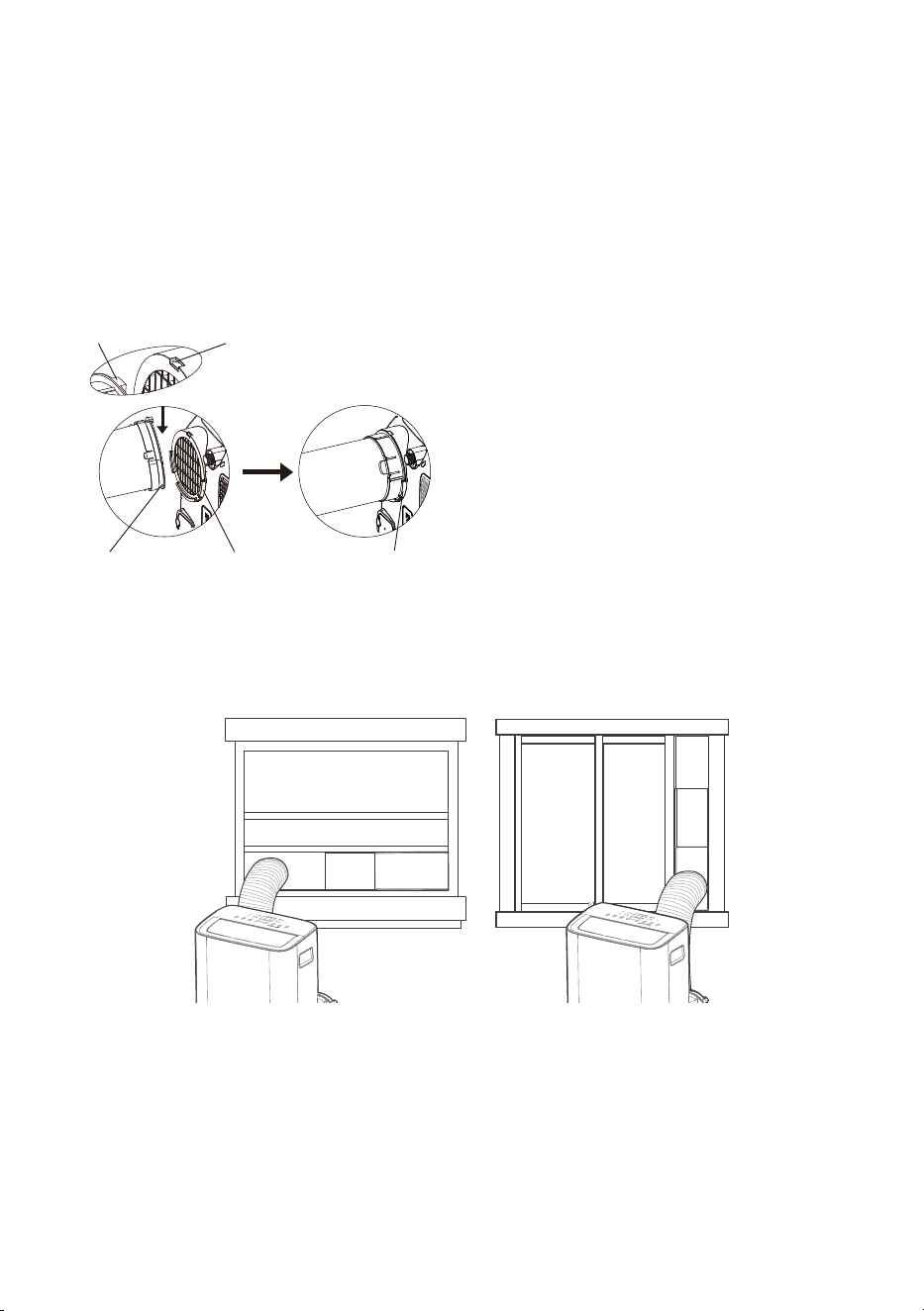
6 - Install The Exhaust Hose Assembly To The Unit:
7 - Connect The Adaptor To The Unit And The Window:
Insert the window slider adapter into the hole of the window slider.
Step 1: Insert the window slider assembly into the window opening.
Step 2: Cut the non-adhesive foam seal C strip to match the height of the window. Insert
the seal between the glass and the window frame to prevent air and insects from
getting into the room.
Step 3: If desired, install the security bracket with 2 screws as shown.
Push the exhaust hose into the air outlet
opening of the unit along the arrow direction.
Hung Window Installation Sliding Window Installation
Hook Hook Seat
Lower
groove
Adapter Make sure the
adaptor is inserted
into the lower groove
of the air outlet.
18
OPERATING INSTRUCTIONS
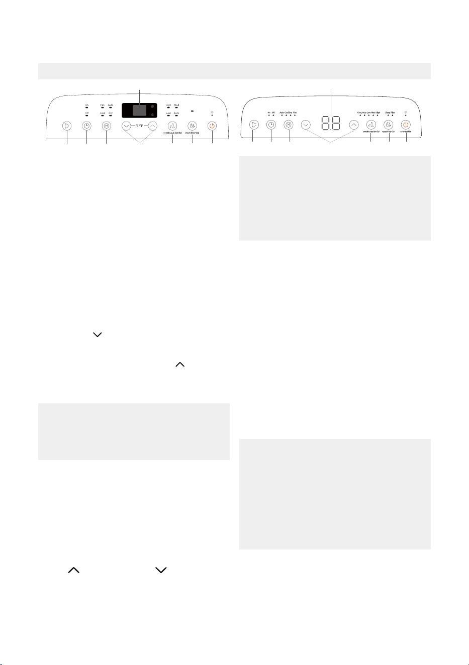
Electronic Control Operating Instructions
1. POWER Button
Used to initiate the Wireless function. For
the first time using the Wireless function,
press and hold the POWER button for 3
seconds to initiate the Wireless connection
mode. The LED DISPLAY shows ‘AP’ to
indicate you can set Wireless connection. If
connection (router) is successful within 8
minutes, the unit will exit Wireless
connection mode automatically and the
Wireless indicator light illuminates.
Power switch on/off .
If connection fails within 8 minutes, the unit
exits Wireless connection mode
automatically. After Wireless connection is
successful, you can press and hold POWER
and DOWN ( /-) buttons at the same time
for 3 seconds to turn off wireless function
and the LED display shows ‘OF’ for 3
seconds, press POWER and UP ( /+) buttons
at the same time to turn on Wireless function
and the LED DISPLAY shows ‘On’ for 3
seconds.
The control is capable of displaying
temperature in degrees Fahrenheit or
degrees Celsius. To convert from one
to the other, press and hold the Up and
Down buttons at the same time for 3
seconds.
NOTICE
When you restart the Wireless function, it
may take a period of time to connect to the
network automatically.
NOTICE
When one of the above malfunctions
occurs, turn off the unit, and check for any
obstructions on any of the air inlet or outlet
vents. Restart the unit, if the malfunction is
still present, turn off the unit and unplug the
power cord.
Contact the manufacturer, its service agents
or a similar qualified person for service.
NOTICE
5. TIMER Button
Used to initiate the AUTO ON start time and
AUTO OFF stop time program in conjuction
with the UP & DOWN buttons. The timer
on/off indicator light illuminates under the
timer on/off settings.
4. DISPLAY
Shows the set temperature in °C or °F and the
Auto-timer settings. While on DRY and FAN
modes, it shows the room temperature.
Shows Error codes and protection code:
EH60-Room temperature sensor error.
EH61-Evaporator temperature sensor error.
EC52-Condenser temperature sensor error
(on some models).
EH0b-Display panel communication error.
ELOC-Refrigerant leakage detection
malfunction (on some models).
P1 - Bottom tray is full - Connect the drain
hose and drain the collected water away. If
protection repeats, call for service.
2. MODE Function
Selects the appropriate operating mode.
Each time you press the button, a mode is
selected in a sequence that goes from AUTO,
COOL, DRY, FAN, and HEAT (heat function
only on some models). The mode indicator
light illuminates under the different mode
settings. See page 19 for more information
on each mode.
3. UP ( /+) and DOWN ( /-) Buttons
Used to adjust (increasing/decreasing)
temperature settings in 1°C/2°F (or 1°F)
increments in a range of 16°C-30°C/60°F-
86°F(or 88°F).
TIMER setting in a range of 0~24hrs.
18
7
2
56
3
4
4
1
87
2 3
56

19
6. SWING Mode
Used to initiate the Auto swing feature. When
the operation is ON, press the SWING button
to stop the louver at the desired angle.
Keep windows and doors closed for the
best dehumidifying effect.
NOTICE
9. DRY Mode
To turn on Dry mode, press the “MODE”
button until the “Dry” indicator light comes
on. In this mode, the fan speed or the
temperature cannot be adjusted.
The fan motor operates at LOW speed.
Under AUTO mode, both the AUTO mode
and the actual operation mode indicator
lights illuminate for some models.
NOTICE
10. AUTO Mode
When you set the air conditioner to AUTO
mode, it will automatically select cooling,
heating (heat function only on some models),
or fan only operation depending on what
temperature you have selected and the room
temperature. To turn on Auto mode, press
the “MODE” button until the “Auto” indicator
light comes on.
The air conditioner will control room
temperature automatically around the
temperature point set by you. Under AUTO
mode, you can not select the fan speed.
12. FAN Mode
To turn on Fan mode, press the “MODE”
button until the “Fan” indicator light comes on.
To control the fan speed, press the Continuous
Fan button in four steps - LOW, MED, HIGH
and AUTO.
The fan speed indicator light will illuminate
under different fan settings.
7. CONTINUOUS FAN Function
In Cool or Dry mode, press and hold the
Continuous Fan button for 3 seconds to turn
the continuous fan function on or off . When
the function is turned on, the continuous fan
light will illuminate. When the function is
turned off , the continuous fan light will turn
off .
13. ComfortSense
To activate the ComfortSense feature, point
the remote control towards the unit and press
the ComfortSense button. The remote’s
display will show actual temperature at its
location and must be within 26 feet of the air
conditioner to work. The remote control will
send this signal to the air conditioner every
3 minutes until the ComfortSense button is
pressed again. If the unit does not receive the
ComfortSense signal during any 7 minute
interval, the unit will beep to indicate the
ComfortSense mode has ended.
This feature is unavailable under FAN or
DRY mode.
NOTICE
8. SLEEP Mode
Press the sleep button to initiate sleep mode.
While in this mode, the selected temperature
will increase or decrease by 2°F (or 1°C) after
30 minutes.
The temperature will then increase or
decrease by another 2°F (or 1°C) after an
additional 30 minutes.
This new temperature will be maintained for 7
hours before it returns to the originally
selected temperature. After the 7 hour period,
sleep mode is automatically turned off and
the unit will continue to operate as originally
programmed.
11. COOL Mode
To turn on Cool mode, press the “MODE”
button until the “Cool” indicator light comes
on.
Press the ADJUST buttons UP ( /+) or
DOWN ( /-) to select your desired room
temperature.
The temperature can be set within a range
of 16°C-30°C/60°F-86°F(or 88°F).
Press the “FAN SPEED” button to choose
the fan speed.
20
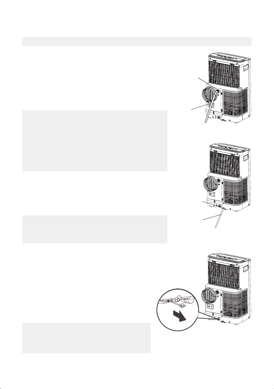
Drainage Guide
Make sure the hose is secure so there are no leaks. Direct
the hose toward the drain, making sure that there are no
kinks that will stop the water flowing. Place the end of
the hose into the drain and make sure the end of the
hose is down to let the water flow smoothly. When the
continuous drain hose is not used, ensure that the
corresponding drain plug and knob are installed firmly to
prevent leakage.
NOTICE
Make sure the drain hose is lower than the bottom tray
drain outlet.
NOTICE
Be sure to reinstall the bottom drain plug firmly
to prevent leakage before using the unit.
NOTICE
During dehumidifying mode, remove the upper drain plug
from the back of the unit, install the drain connector (5/8”
universal female mender) with 3/4” hose (not inlcuded).
For the models without drain connector, just attach the
drain hose to the hole. Place the open end of the hose
directly over the drain area in your basement floor. During
heat pump mode(only on some models), remove the lower
drain plug from the back of the unit, install the drain
connector.
During heat pump mode(only on some models), remove
the lower drain plug from the back of the unit, install the
drain connector (5/8” universal female mender) with 3/4”
hose (not inlcuded).
Carefully move the unit to a drain location, and let the
water drain away.
Continuous
drain hose
Remove the
upper drain
plug
Continuous
drain hose
Remove the
lower drain
plug
When the water level of the bottom tray reaches a
predetermined level, the unit beeps 8 times, the digital
display area shows “P1”. At this time the air conditioning/
dehumidification process will immediately stop. However,
the fan motor will continue to operate (this is normal).
Carefully move the unit to a drain location, remove
the bottom drain plug and let the water drain away.
Reinstall the bottom drain plug and restart the
machine until the “P1” symbol disappears. If the
error repeats, call for service.
21
CLEANING & MAINTENANCE
Air Filter & Cabinet Cleaning
Maintenance Tips
Clean the unit using a damp, lint-free cloth and mild
detergent.
Dry the unit with a dry, lint-free cloth.
• Take the filter out along the arrow direction.
• Wash the air filter by immersing it gently in warm water
(about 40°C/104°F) with a neutral detergent.
• Rinse the filter and dry it in a shady place.
• Install the air filter after cleaning.
• Be sure to clean the air filter every 2 weeks for optimal performance.
• The water collection tray should be drained immediately after P1 error occurs, and before
storage to prevent mold.
• In households with animals, you will have to periodically wipe down the grill to prevent
blocked airflow due to animal hair.
DO NOT operate the unit without filter because dirt and
lint will clog it and reduce performance.
CAUTION
Remove the air filter
• Always unplug the unit before cleaning or servicing.
• DO NOT use flammable liquids or chemicals to clean the unit.
• DO NOT wash the unit under running water. Doing so causes electrical danger.
• DO NOT operate the machine if the power supply was damaged during cleaning. A
damaged power cord must be replaced with a new cord from the manufacturer.
CAUTION
22
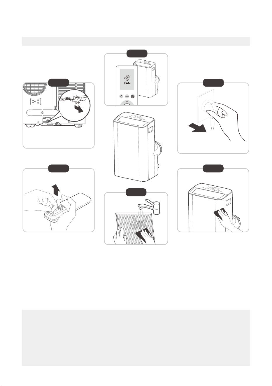
Store The Unit When Not In Use
Step 1: Drain the unit’s water collection tray according to the instructions on page 20.
Step 2: Run the appliance on FAN mode for 12 hours in a warm room to dry it and prevent
mold.
Step 3: Turn off the appliance and unplug it.
Step 4: Clean the machine.
Step 5: Clean the air filter according to the instructions in the previous section. Reinstall the
clean, dry filter before storing.
Step 6: Remove the batteries from the remote control.
NOTICE
• Be sure to store the unit in a cool, dark place. Exposure to direct sunshine or extreme
heat can shorten the lifespan of the unit.
• The cabinet and front may be dusted with an oil-free cloth or washed with a cloth
dampened in a solution of warm water and mild liquid dishwashing detergent. Rinse
thoroughly and wipe dry. Never use harsh cleansers, wax or polish on the cabinet front.
Be sure to wring excess water from the cloth before wiping around the controls. Excess
water in or around the controls may cause damage to the unit.
12hours
Step6
Step 3
Step4
Step 1
Step 2
Step 5
*Drain the unit‘s water collection
tray then reinstall the bottom
drain plug back in.
*Please refer to the
actual plug, and the
legend is for reference only.

23
Decrease the set temperature.
Call a service technician to inspect
the unit and top off refrigerant.
The water collection tray is full.
Turn off the unit, drain the water from
the Water Collection Tray and restart
the unit.
Common Issues
The following problems are not a malfunction and in most situations will not require repairs.
Proble Solution
Unit does not
turn on when
pressing
ON/OFF button
P1 Protection Code.
In COOL mode: room temperature
is lower than the set temperature.
Check the set temperature.
Unit does not
cool well
The air filter is blocked with dust
or animal hair.
Turn off the unit and clean the filter
according to instructions.
Exhaust hose is not connected or
is blocked.
Turn off the unit, disconnect the hose,
check for blockage and reconnect the
hose.
The unit is low on refrigerant.
Temperature setting is too high.
The windows and doors in the
room are open.
Make sure all windows and doors are
closed.
The room area is too large.
There are heat sources inside the
room.
Remove the heat sources if possible.
The unit is noisy
and vibrates too
much
The ground is not level Place the unit on a flat, level surface.
The air filter is blocked with dust
or animal hair.
Turn off the unit and clean the filter
according to instructions.
The unit makes a
gurgling sound
This sound is caused by the
refrigerant flow inside the unit.
This is normal.
Double-check the cooling area.
TROUBLESHOOTING TIPS
24
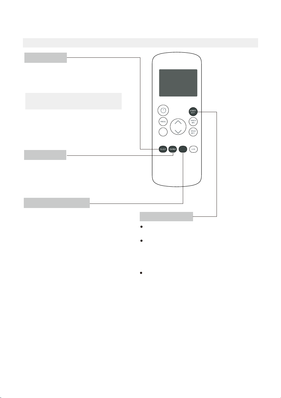
REMOTE CONTROL AND APP INSTRUCTIONS
Remote Control Specifications
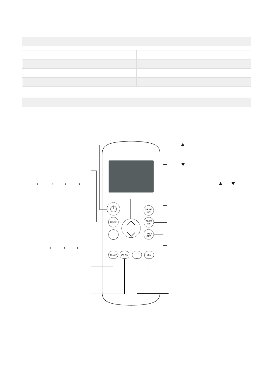
Function Buttons
Before you begin using your new air conditioner, make sure to familiarize yourself with its
remote control. The following is a brief introduction to the remote control itself. For
instructions on how to operate your air conditioner, refer to the Operating Instructions
section of this manual.
COMFORTSENSE
Turns the ComfortSense feature on and off.
SHORT CUT
Sets and activates your favorite pre-settings.
Turns the unit on or off.
TEMP
Increases temperature in 1° increments.
Max. temperature is 86°F (30°C).
TIMER ON
Sets timer to turn unit on.
TIMER OFF
LED
Turns the AC’s LED display on and off.
SWING
Starts and stops
louver movement.
SLEEP
Saves energy during
sleeping hours.
TEMP
Decreases temperature in 1° increments.
Min. temperature is 60°F (16°C).
NOTE: Pressing and holding and buttons
together for 3 seconds will alternate the
temperature display between the °F & °C scale.
Selects fan speeds in the
following order:
AUTO LOW MED HIGH
MODE
Scrolls through operation modes
as follows:
AUTO COOL DRY HEAT FAN
NOTE:
Please do not select HEAT mode
if the machine you purchased is
cool-only type. Heat mode is not
supported by cool-only models.
ON/OFF
FAN SPEED
C-SENSE
FAN
Sets timer to turn unit off.
Model
Rated voltage
Signal receiving range
Environment
RG57H4(B2)/BGCEU1
3.0V (Dry batteries R03/LR03x2)
26 ft. (approx. 8 m)
23°F ~ 140°F (-5°C ~ 60°C)
25
Handling the Remote Control
NOT SURE WHAT A FUNCTION DOES?
Refer to the Operating Instructions section of this manual for a detailed description of the
functions available using the remote.
NOTICE
Button designs on your unit may differ slightly from the example shown.
If the unit does not have a specific function, using that function’s button on the remote
control will have no effect.
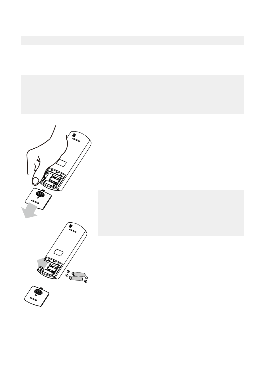
INSERTING AND REPLACING BATTERIES
Your air conditioning unit comes with two AAA batteries.
Insert the batteries in the remote control before use.
1. Slide the back cover of the remote control downward,
exposing the battery compartment.
2. Insert the batteries, paying attention to align the (+) and
(-) ends of the batteries with the symbols inside the
battery compartment.
3. Slide the battery cover back into place.
BATTERY DISPOSAL
Ensure used batteries are disposed of properly.
TIPS FOR USING REMOTE CONTROL
• The remote control must be used within 26 feet / 8 meters
of the unit.
• The unit will beep when it receives a signal from the remote.
Curtains, other materials and direct sunlight can interfere
with the IR signal receiver.
• In order to properly transmit a command, the ON/OFF
indicator must be illuminated on the remote’s display. (See
the Remote LED Screen Indicators section for more
information.)
BATTERY NOTES
For optimum product performance:
• Do not mix old and new batteries, or batteries of
different types.
• Do not leave batteries in the remote control if you don’t
plan on using the device for more than 2 months.
26
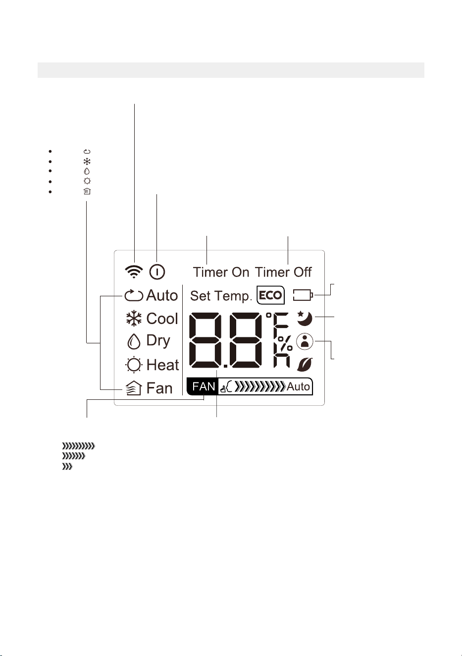
AUTO
COOL
DRY
HEAT
FAN
Transmission Indicator
Lights up when remote sends signal to unit
MODE display
Displays the current
mode, including:
TIMER ON display
Displays when
TIMER ON is set
TIMER OFF display
Displays when
TIMER OFF is set
Battery display
Low battery detection
SLEEP display
Displays when SLEEP
function is activated
FAN SPEED display
Displays selected FAN SPEED:
HIGH
MED
LOW
This display is blank when
set to AUTO speed.
Temperature/Timer display
Displays the set temperature by default, or timer setting
when using TIMER ON/OFF functions:
- Temperature range: 60°F-86°F (16°C-30°C)
- Timer setting range: 0-24 hours
This display is blank when operating in FAN mode.
ON/OFF display
Appears when the remote is enabled and can send a signal to the unit.
If you would like to turn the remote off without affecting the unit, point
the remote away from the unit and press the ON/OFF button.
To turn the remote on, point the remote away from the unit and press
the ON/OFF button.
The unit will not receive commands from the remote if this indicator is
not illuminated.
COMFORTSENSE display
Indicates that the
COMFORTSENSE function
is on
Remote LED Screen Indicators
27
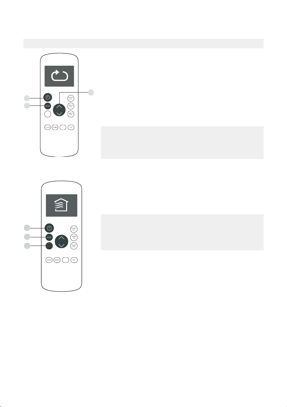
Basic Functions
SETTING THE DESIRED TEMPERATURE
The operating temperature range for this unit is 60°F-86°F
(16°C-30°C).
You can increase or decrease the set temperature in 1°F or 1°C
increments.
Changing the Mode
1. To change the operating mode, press the MODE button until
the desired mode appears on the remote’s display.
2. Set the desired temperature.
NOTICE
If the unit does not change when the button is pressed, check
that the ON/OFF indicator is illuminated. If it is not, point the
remote at the unit and press the ON/OFF button.
NOTICE
If the unit does not change when the button is pressed,
check that the ON/OFF indicator is illuminated. If it is not,
point the remote at the unit and press the ON/OFF button.
Changing the Fan Speed
To change the fan speed, press the FAN button until the
desired fan speed appears on the remote’s display.
1
3
2
FOLLOW
ME
C-SENSE
FAN
1
2
3
FOLLOW
ME
C-SENSE
FAN
28
Timer Functions
NOTICE
This number indicates the amount of time after the current
time after which you want the unit to turn on.
For example, if you set TIMER ON for 2 hours, “2.0h“ will
appear on the screen, and the unit will turn on after 2 hours.
Your air conditioning unit has two timer-related functions:
TIMER ON - sets the amount of time after which the unit will
automatically turn on.
TIMER OFF - sets the amount of time after which the unit will
automatically turn off.
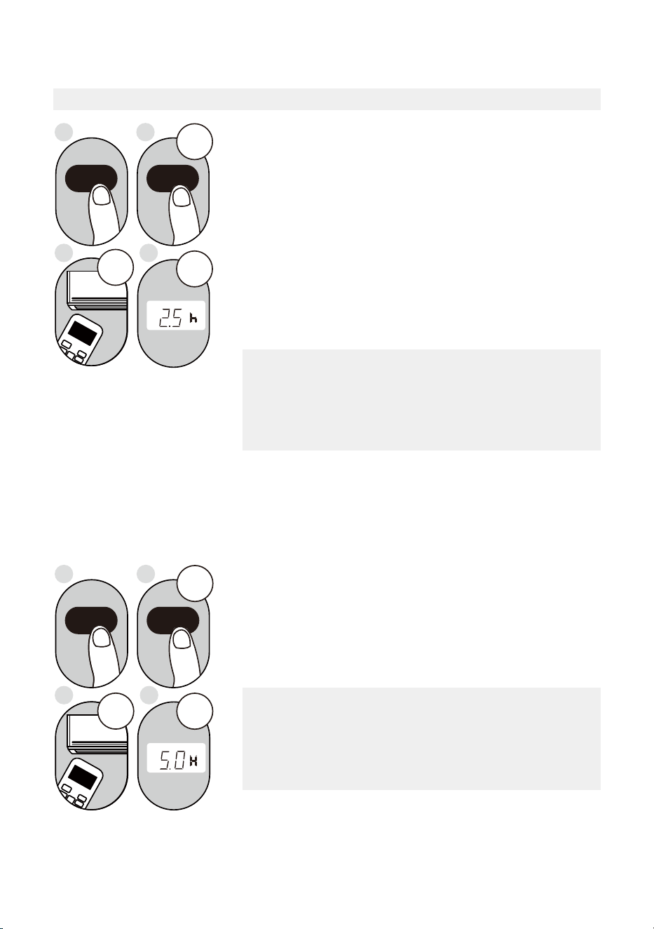
TIMER ON Function
The TIMER ON function allows you to set a period of time
after which the unit will automatically turn on, such as when
you come home from work.
1. Press the TIMER ON button. By default, the last time
period that you set and an “h” (indicating hours) will
appear on the display.
2sec
ON/OFF
MODE
FAN
SHORT
CUT
TIMER ON
TIMER OF
F
TEMP
S
L
E
EP
1sec
x5
1
3
2
4
TIMER ON TIMER ON
Example: Setting unit to turn
on after 2.5 hours.
2. Press the TIMER ON button repeatedly to set the time
that you want the unit to turn on.
3. Wait 2 seconds, then the TIMER ON function will be
activated. The digital display on your remote control will
then return to the temperature display.
2sec
x10
ON/OFF
MODE
F
AN
SHORT
CUT
TIMER ON
TIMER OF
F
TEMP
S
LEEP
1 sec
1
3
2
4
TIMER OFF
TIMER OFF
Example: Setting unit to turn
off after 5 hours.
TIMER OFF Function
The TIMER OFF function allows you to set a period of time
after which the unit will automatically turn off, such as when
you wake up.
1. Press the TIMER OFF button. By default, the last time
period that you set and an “h” (indicating hours) will
appear on the display.
2. Press the TIMER OFF button repeatedly to set the time
that you want the unit to turn off.
This number indicates the amount of time after the current
time after which you want the unit to turn off.
For example, if you set TIMER OFF for 2 hours, “2.0h“ will
appear on the screen, and the unit will turn off after 2 hours.
NOTICE
29
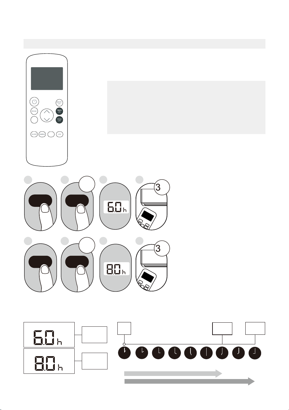
Timer Functions (cont.)
3. Wait 2 seconds, then the TIMER OFF function will be
activated. The digital display on your remote control will
then return to the temperature display.
NOTICE
When setting the TIMER ON or TIMER OFF functions, up
to 10 hours, the time will increase in 30 minute increments
with each press. After 10 hours and up to 24, it will increase
in 1 hour increments. The timer will revert to zero after 24
hours.
You can turn off either function by setting the timer to “0.0h“.
ON/OFF
MODE
SHORT
CUT
TIMER ON
TEMP
sec
4
ON/OFF
MODE
SHORT
CUT
TIMER ON
TEMP
sec
8
1
TIMER ON
X12
2
TIMER ON
5
TIMER OFF
X16
6
TIMER OFF
3
7
Setting Both TIMER ON And
TIMER OFF At The Same Time
Keep in mind that the time periods
you set for both functions refer to
hours after the current time. For
example, say that the current time
is 1:00 PM, and you want the unit
to turn on automatically at 7:00 PM
and want it to operate for 2 hours,
then automatically turn off at
9:00 PM.
Do the following (side figure):
Example: Setting the unit to turn on after 6 hours, operate for 2 hours, then turn off (see the
figure below).
Timer On
Timer Off
Timer is set
To turn ON
6 hours from
current time
Timer is set
To turn OFF
8 hours from
current time
Current
Time 1PM
2PM 3PM
4PM 5PM
6PM 7PM 8PM 9PM
Unit turns
ON
Unit turns
OFF
6 hours later
8 hours later
Timer
Starts
Your remote display
T i m e r o n
Continue
to press
TIMER ON
or
TIMER OFF
until desired
time is
reached.
FOLLOW
ME
C-SENSE
FAN
30
How to Use the Advanced Functions
SHORTCUT Function
SWING Function
COMFORTSENSE Function
SLEEP Function
The SLEEP function is used to decrease
energy use while you sleep (and don’t need
the same temperature settings to stay
comfortable).
Used t
The COMFORTSENSE function enables the
remote control to measure the temperature
at its current location.
When using AUTO, COOL, or HEAT functions,
measuring ambient temperature from the
remote control (instead of from the indoor
unit itself) will enable the air conditioner to
optimize the temperature around you and
ensure maximum comfort.
1. Press COMFORTSENSE button to activate
function.
The remote control will send temperature
signal to the unit every three minutes.
2. Press COMFORTSENSE button again to
turn off this function.
o stop or start louver movement and set the
desired up/down air flow direction. The louver
angle changes in 6 degree increments with each
press (not all models). By pressing for more than 2
seconds, the louver auto swing feature is activated.
Used to restore the current settings or resume
previous settings.
Push this button when remote controller is on,
the system will automatically revert back to the
previous settings including operating mode,
set temperature, fan speed level and sleep
feature (if activated).
By pressing for more than 2 seconds, the
system will automatically store the current
operation settings including operating mode,
set temperature, fan speed level and sleep
feature (if activated).
Note:
The SLEEP function is not
available in FAN or DRY mode.
C-SENSE
FAN

31
This device complies with part 15 of the FCC Rules. Operation is subject to the following
two conditions: (1) This device may not cause harmful interference, and (2) this device
must accept any interference received, including interference that may cause undesired
operation.
Note: This equipment has been tested and found to comply with the limits for a Class B
digital device, pursuant to part 15 of the FCC Rules. These limits are designed to provide
reasonable protection against harmful interference in a residential installation. This
equipment generates, uses and can radiate radio frequency energy and, if not installed
and used in accordance with the instructions, may cause harmful interference to radio
communications. However, there is no guarantee that interference will not occur in a
particular installation.
If this equipment does cause harmful interference to radio or television reception, which
can be determined by turning the equipment off and on, the user is encouraged to try to
correct the interference by one or more of the following measures:
• Reorient or relocate the receiving antenna.
• Increase the separation between the equipment and receiver.
• Connect the equipment into an outlet on a circuit different from that to which the
receiver is connected.
• Consult the dealer or an experienced radio/TV technician for help.
NOTICE

32
Declaration of Conformity
CONTAINS FCC ID: 2ADQOMDNA21
CONTAINS IC : 12575A-MDNA21
This device complies with Part 15 of the FCC Rules and it contains license-exempt
transmitter(s)/receiver(s) that comply with Innovation, Science and Economic
Development Canada’s license exempt RSS(s). Operation is subject to the following
two conditions:
(1) This device may not cause interference; and
(2) This device must accept any interference,including interference that may cause
undesired operation of the device.
Only operate the device in accordance with the instructions supplied. Changes or modifi
cations to this unit not expressly approved by the party responsible for compliance could
void the user’s authority to operate the equipment. This device complies with FCC radiation
exposure limits set forth for an uncontrolled environment. In order to avoid the possibility
of exceeding the FCC radio frequency exposure limits, human proximity to the antenna
shall not be less than 20cm (8 inches) during normal operation.
Note: This equipment has been tested and found to comply with the limits for a Class B
digital device, pursuant to part 15 of the FCC Rules. These limits are designed to provide
reasonable protection against harmful interference in a residential installation. This
equipment generates, uses and can radiate radio frequency energy and, if not installed
and used in accordance with the instructions, may cause harmful interference to radio
communications. However, there is no guarantee that interference will not occur in a
particular installation. If this equipment does cause harmful interference to radio or
television reception, which can be determined by turning the equipment off and on, the
user is encouraged to try to correct the interference by one or more of the following
measures:
• Reorient or relocate the receiving antenna.
• Increase the separation between the equipment and receiver.
• Connect the equipment into an outlet on a circuit different from that to which the
receiver is connected.
• Consult the dealer or an experienced radio/TV technician for help.
Company will not be liable for any issues and problems caused by Internet, Wi-Fi/ Wireless
Router and Smart Devices. Please contact the original provider to get further help.
NOTICE

33
Supplier’s Declaration of Conformity
47 CFR § 2.1077 Compliance Information
Unique Identifier: RG57H4(B2)/BGCEFU1
Responsible Party U.S. Contact Information
Midea America Corporation
300 Kimball Dr
Parsippany NJ
07054
Telephone number or internet contact information: Midea.com/us
FCC Compliance Statement (products subject to Part 15)
This device complies with Part 15 of the FCC Rules. Operation is subject to the following
two conditions: (1) This device may not cause harmful interference, and (2) this device
must accept any interference received, including interference that may cause undesired
operation.
34
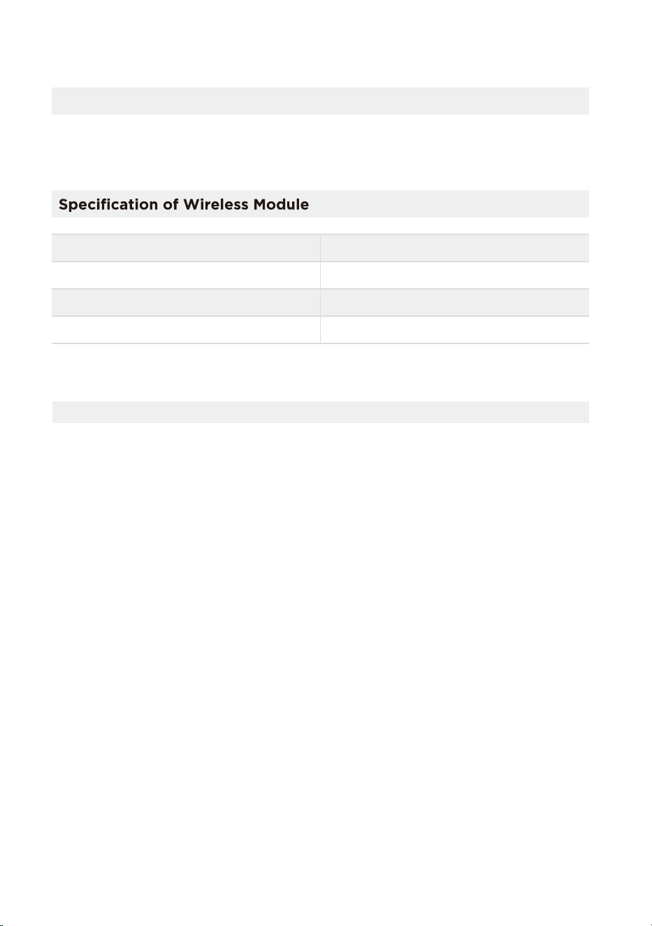
Declaration of Conformity
We hereby declare that this AC is in compliance with the essential requirements and
other relevant provisions of Directive 1999/5/EC.
Model: US-SK105 Dimensions: 41 x 24 x 5 (mm)
Operation Temperature: 0°C ~ 45°C / 32°F ~ 113°F
Antenna Type: Printed PCB Antenna
Operation Humidity: 10% ~ 85%
Frequency: WLAN 2400-2483.5 MHz
Power Input: DC 5V/500 mA
Maximum Transmitted Power: <20 dBm Max
1. Supports operating systems: Please refer to page 35
2.
In the event of a OS update, there may be a delay between the update of the OS
and a related software update during which your OS may or may not be supported
until a new version is released. Your specific mobile phone or problems in your
network may prevent the system from working and Midea will not be responsible
for any problems that could be caused by incompatibility or network issues.
3.
This Smart AC only supports WPA-PSK/WPA2-PSK (recommended) encryption.
4.
To ensure proper scanning of the QR code, your smart phone must have at least a
5-megapixel camera.
5.
Due to unstable network connectivity, requests may time out. If this happens, rerun
the network configuration.
6. Due to unstable network connectivity, commands may time out. If this happens,
the smartphone app and the actual product may display conflicting information.
The information displayed on the actual product is always the most accurate
available. Refresh the app to re-sync.
PRECAUTIONS

Midea will not be responsible for any problems that could be caused by
incompatibility or network issues, your wireless router and mobile phone.
NOTICE
NOTE:
The functions shown in the Alexa, Google Home or Apple Home apps may change with updates to
their products or apps.
Setup processes and features may vary between ecosystems.
Periodically, we will update the device’s software to improve the experience.
Device software updates can be accomplished through the SmartHome app.
9094439556
Google Play services min version: 22.36.15
Google Home app (GHA) min version: 2.58.24.1-dogfood
Google Hub firmware min version: 1.56.324896
(appears on hub as Chromecast firmware version)
2.2.536317
16.5
Device Version
iOS 16.5iPhone
Apple Home
Pod
Alexa Echo
Device
Android
Google
Home Hub
Alexa App
35
1
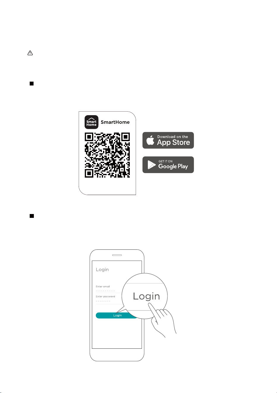
How to use SmartHome App (smart models only)
Ensure that your mobile phone is connected to the wireless network. Bluetooth must be turned on.
The device must also be powered up.
Scan the QR code below to download the SmartHome app from app store or search for it directly
on the Google Play Store or Apple's App Store.
Step 1: Download the SmartHome app
Open the SmartHome app. Log in directly if you have an existing SmartHome account or create a
new account. Alternatively, you can also use a 3rd party login platform.
Step 2: Log in
Download the app
& activate product
36
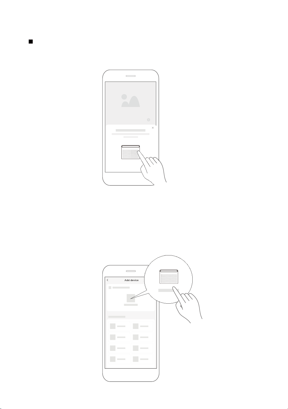
1) When you log in, you may see the message "Smart devices discovered nearby".
Tap to add your device.
2) If no such message appears, proceed as follows: Tap on "+" and select your device in the list of
nearby available devices.
If your device is not listed, please add your device manually, first selecting the device category e.g.
Window AC.
Step 3: Connecting the device
37
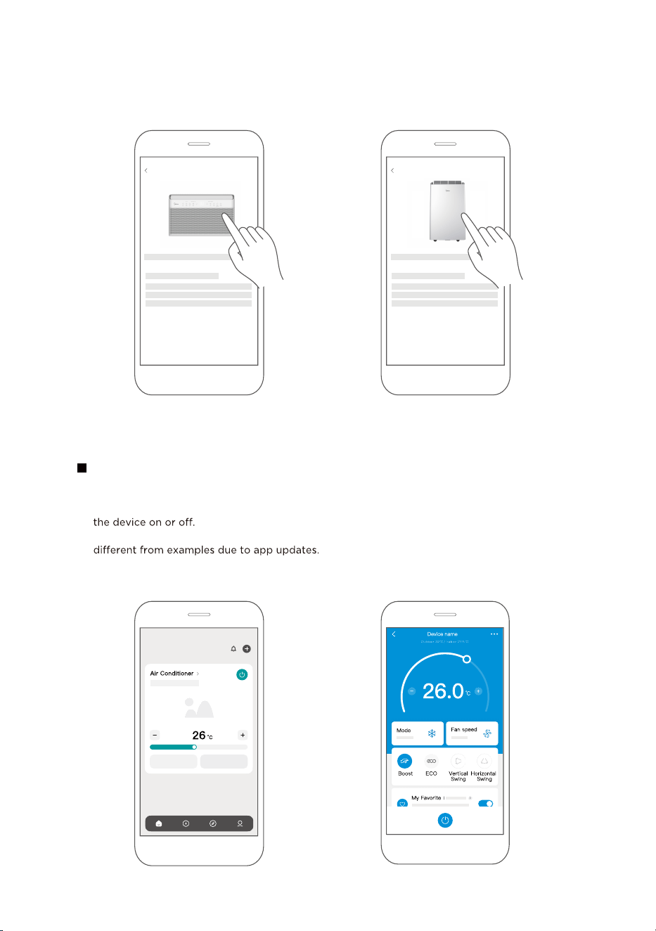
After pairing successfully, a card will be created for the device in the SmartHome app.
Shortcuts for basic functions will appear on the card such as changing the temperature or switching
Tapping on the card, will reveal additional features and settings. The actual UI design may look
Step 4: Controlling the device
SmartHome
3) Follow the steps in the app to connect your device to the wireless network. If your device fails to
connect, follow the additional instructions in the app.
Add device
For Window AC For Portable
AC
Add device
38

WARNING: Chemical Burn Hazard. Keep batteries away from children.
This product contains a lithium button/coin cell battery. If a new or used lithium button/coin cell battery
is swallowed or enters the body, it can cause severe internal burns and can lead to death in as little as 2
hours. Always completely secure the battery compartment. If the battery compartment does not close
securely, stop using the product, remove the batteries, and keep it away from children. If you think
batteries might have been swallowed or placed inside any part of the body, seek immediate medical
attention.

CWS002IU-TYN8(GF)
20231125