Loading ...
Loading ...
Loading ...
AXISC8110NetworkAudioBridge
Specifications
microSD,microSDHC,andmicroSDXCLogosaretrademarksofSD-3CLLC.microSD,microSDHC,microSDXCare
trademarksorregisteredtrademarksofSD-3C,LLCintheUnitedStates,othercountriesorboth.
Buttons
Controlbutton
Thecontrolbuttonisusedfor:
•Calibratingthespeakertest.Pressandreleasethecontrolbuttonandatesttoneisplayed.
•Resettingtheproducttofactorydefaultsettings.SeeResettofactorydefaultsettingsonpage30.
Connectors
Networkconnector
RJ45EthernetconnectorwithPoweroverEthernet(PoE).
NO NO
NO
TICE TICE
TICE
Theproductshallbeconnectedusingashieldednetworkcable(STP).Allcablesconnectingtheproducttothenetworkshall
beintendedfortheirspecicuse.Makesurethatthenetworkdevicesareinstalledinaccordancewiththemanufacturer’s
instructions.Forinformationaboutregulatoryrequirements,seetheInstallationGuideatwww.axis.com.
I/Oconnector
UsetheI/Oconnectorwithexternaldevicesincombinationwith,forexample,motiondetection,eventtriggering,andalarm
notications.Inadditiontothe0VDCreferencepointandpower(DCoutput),theI/Oconnectorprovidestheinterfaceto:
Digitalinput-Forconnectingdevicesthatcantogglebetweenanopenandclosedcircuit,forexamplePIRsensors,door/window
contacts,andglassbreakdetectors.
Digitaloutput-ForconnectingexternaldevicessuchasrelaysandLEDs.ConnecteddevicescanbeactivatedbytheVAPIX®
ApplicationProgrammingInterface,troughaneventorfromtheproduct’swebpage.
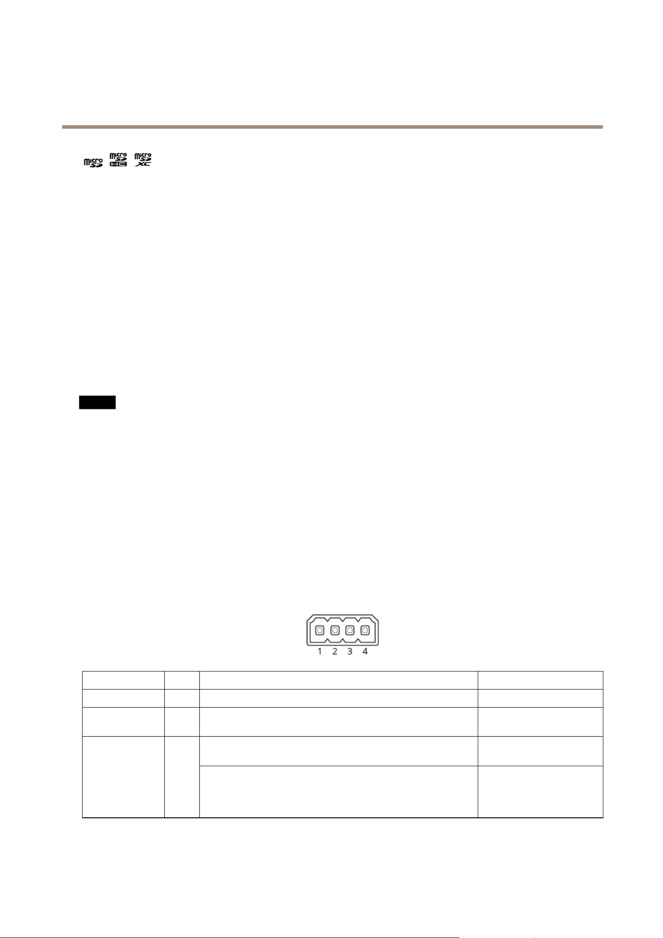
4-pinterminalblock
FunctionPinNotes
Specications
DCground
1
0VDC
DCoutput
2
Canbeusedtopowerauxiliaryequipment.
Note:Thispincanonlybeusedaspowerout.
12VDC
Maxload=50mA
Digitalinput–Connecttopin1toactivate,orleaveoating
(unconnected)todeactivate.
0tomax30VDC Congurable
(InputorOutput)
3–4
Digitaloutput–Internallyconnectedtopin1(DCground)when
active,andoating(unconnected)wheninactive.Ifusedwithan
inductiveload,e.g.,arelay,connectadiodeinparallelwiththeload,
toprotectagainstvoltagetransients.
0tomax30VDC,opendrain,
100mA
Example
34
Loading ...
Loading ...
Loading ...