Electric Continuous Flow Water Heater
Operation & Installation Manual
MODELS
ECF29I50 ECF19I50
ECF29I60 ECF19I60
Rinnai 2 ELECTRIC CFWH_OIM - Issue 1
Congratulations on the purchase of your Rinnai Electric Continuous Flow Water Heater. We trust you will have
many years of comfort and satisfaction from your appliance.
IMPORTANT
BEFORE USING THIS APPLIANCE
Before proceeding with the operation or installation read this manual thoroughly and gain a full
understanding of the appliance, to ensure safe and correct use.
This appliance must be installed in accordance with:
• Manufacturer’s Installation Instructions
• Current AS/NZS 3000 & AS/NZS 3500
• Plumbing Code of Australia (PCA) or New Zealand
Building Code
• Local Regulations and Municipal Building Codes
including local OH&S requirements
This appliance must be installed, maintained and
removed by an Authorised Person.
For continued safety of this appliance it must be installed
and maintained in accordance with the manufacturer’s
instructions.
This Appliance complies
with current AS 3498
LIC. WM-032245
Lead Free

Rinnai 3 ELECTRIC CFWH_OIM - Issue 1
OPERATION TABLE OF CONTENTS
Warnings & Important Information 4
Before Using This Appliance ���������������������������������������������������������������������������������������������������������������������������������������������� 4
Regulatory Information ������������������������������������������������������������������������������������������������������������������������������������������������������� 4
Notice to Victorian Consumers ������������������������������������������������������������������������������������������������������������������������������������������ 4
Mandatory Inspection Prior to Installation or Use ������������������������������������������������������������������������������������������������������������ 4
Scald Hazards ���������������������������������������������������������������������������������������������������������������������������������������������������������������������� 5
Operational Safety Information ����������������������������������������������������������������������������������������������������������������������������������������� 6
About Your Heater 8
Maximum Delivery Temperature ����������������������������������������������������������������������������������������������������������������������������������������� 8
Temperature Control ��������������������������������������������������������������������������������������������������������������������������������������������������������� 8
Features & Benets ������������������������������������������������������������������������������������������������������������������������������������������������������������� 8
Operation 9
Control Panel Console Operation �������������������������������������������������������������������������������������������������������������������������������������� 9
Maintenance 11
Turning Water Heater ‘O’ ��������������������������������������������������������������������������������������������������������������������������������������������������11
Turning Water Heater ‘On’ ��������������������������������������������������������������������������������������������������������������������������������������������������11
Cleaning and Inspection ���������������������������������������������������������������������������������������������������������������������������������������������������11
Draining �������������������������������������������������������������������������������������������������������������������������������������������������������������������������������11
Trouble Shooting 12
Error Codes ������������������������������������������������������������������������������������������������������������������������������������������������������������������������ 12
Save a Service Call ������������������������������������������������������������������������������������������������������������������������������������������������������������ 12
Service �������������������������������������������������������������������������������������������������������������������������������������������������������������������������������� 13
Installation Table of Contents 14
Contacts 28

Rinnai 4 ELECTRIC CFWH_OIM - Issue 1
WARNING
BEFORE USING THIS APPLIANCE
Before proceeding with the operation or installation read this manual thoroughly and gain a full
understanding of the appliance, to ensure safe and correct use.
Always comply with the following precautions to avoid dangerous situations and to ensure
optimum performance.
Failure to carefully read and follow all instructions in this manual can result in equipment
malfunction, property damage, personal injury and/or death.
DANGER: Indicates an imminently hazardous situation which, if not avoided, will result in
personal injury or death.
WARNINGS: Indicates a potentially hazardous situation which, if not avoided, could result in
personal injury or death.
CAUTIONS: Indicates a potentially hazardous situation which, if not avoided, could result in
minor or moderate injury or damage to the appliance. It may also be used to alert against unsafe
practices.
WARNING
REGULATORY INFORMATION
This appliance MUST be installed in accordance with these instructions and all regulatory
requirements which exist in your area including those in relation to manual lifting, working at
heights and on roofs. Applicable publications and regulations will include:
• AS/NZS 3500 National Plumbing and Drainage
• AS/NZS 3000 Wiring rules
• Plumbing Code of Australia (PCA)
• Building Codes of Australia (BCA) or New Zealand Building Code
• Local Occupational Health and Safety (OH&S) regulations
• Local Regulations and Municipal Building Codes
This appliance MUST be installed, commissioned and serviced correctly by an appropriately
licensed tradesperson. The installation of water and electricity must conform to local regulations.
For continued safety of this appliance it MUST be installed, operated and maintained in
accordance with the manufacturer’s instructions.
Please keep this instruction booklet in a safe place for future reference.
All dimensions referred to in these instructions are in millimetres, unless otherwise specied.
Notice to Victorian Consumers
This appliance MUST be installed by a person licensed with the Victorian Building Authority.
Only a licensed person will have insurance protecting their workmanship. So make sure you use
a licensed person to install this appliance and ask for your Compliance Certicate.
For further information contact the Victorian Building Authority on 1300 815 127.
WARNING
MANDATORY INSPECTION PRIOR TO INSTALLATION OR USE
Immediately report any damage or discrepancies to the Supplier of the appliance. This appliance
was inspected and tested at the time of manufacture and packaging, and released for transportation
without known damage. Upon receipt, inspect the exterior for evidence of rough handling in
shipment. Ensure that the appliance is labelled correctly for the electrical supply, and/or other
services it is intended to be connected to. For safety and warranty purposes, appliances that
may be damaged or incorrect MUST NOT be installed or operated under any circumstances.
Installation of damaged or incorrect appliances may contravene local government regulations.
Rinnai disclaims any liability or responsibility whatsoever in relation to the installation or
operation of damaged or incorrect appliances.
WARNINGS & IMPORTANT INFORMATION
Rinnai 5 ELECTRIC CFWH_OIM - Issue 1
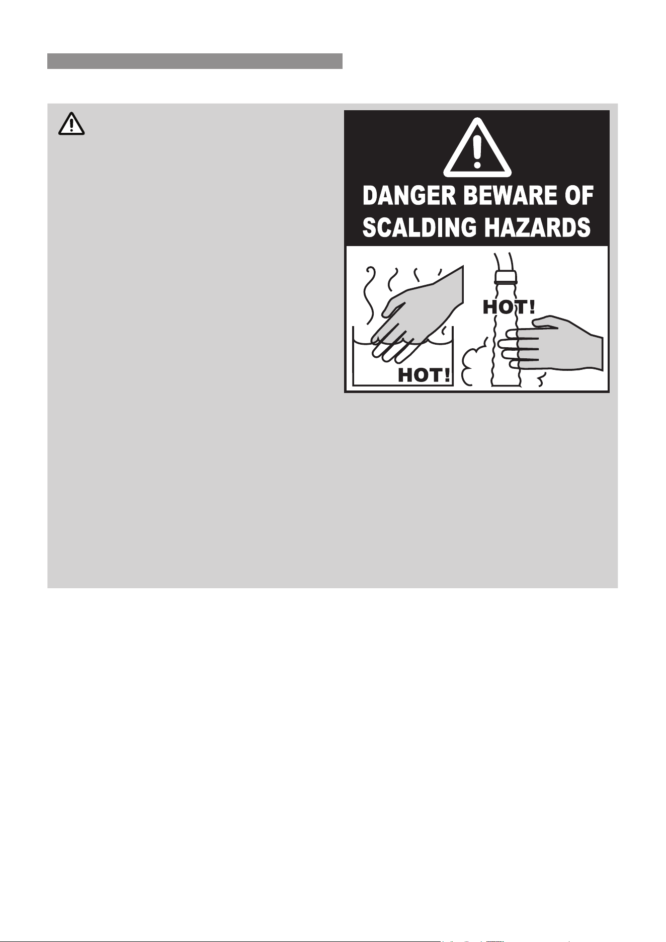
SCALD HAZARDS
WARNING
Hot water can cause scalding.
Those most at risk are children and
disabled, elderly and inrm persons.
Feel water temperature before bathing or
showering.
Scalds can occur when children are
exposed directly to hot water when they are
placed into a bath which is too hot.
Rinnai have water heater models which
limit the delivery temperature to 50°C which
signicantly reduces the scald hazard.
Always......
Test the water temperature with your elbow
before placing your child in the bath, also
carefully feel water temperature before
bathing or showering yourself.
Supervise children whenever they are in
the bathroom or near other sources of hot
water.
Ensure any hot water taps are closed rmly after use.
Consider......
Installing child proof tap covers or child resistant taps (both approaches will prevent a small
hand being able to turn on the tap).
Installing tempering valves or thermostatic mixing valves which reduce the hot water temperature
delivered to the taps. Your local plumbing authority may already require that these be tted.
Contact your installer or local plumbing authority if in doubt.
Never…..
Leave a toddler in the care of another child. They may not understand the need to have the water
temperature set at a safe level.
WARNINGS & IMPORTANT INFORMATION
Rinnai 6 ELECTRIC CFWH_OIM - Issue 1
Operational Safety Information
IMPORTANT
This appliance is NOT intended for use by persons (including children) with reduced physical,
sensory or mental capabilities, or lack of experience and knowledge, unless they have been given
supervision or instruction concerning use of the appliance by a person responsible for their
safety. Children MUST be supervised to ensure that they DO NOT play with the appliance.
DO NOT operate this system before reading the manufacturer's instructions.
Take care when opening or unpacking this appliance. Failure to do so may result in serious injury
or product failure.
DO NOT modify the electrical wiring of this appliance. If the control power wiring is damaged
or deteriorated then it must be replaced by an authorised person. Failure to do so may result in
electric shock, re, serious injury or product failure.
Removal of the access covers of the water heater will expose 415V 3 phase electrical supply.
Access covers MUST ONLY be removed by an authorised person.
Care should be taken not to touch the pipe work as it may be HOT!
This appliance is NOT suitable for use as a domestic spa pool or swimming pool heater.
S
O
L
V
E
N
T
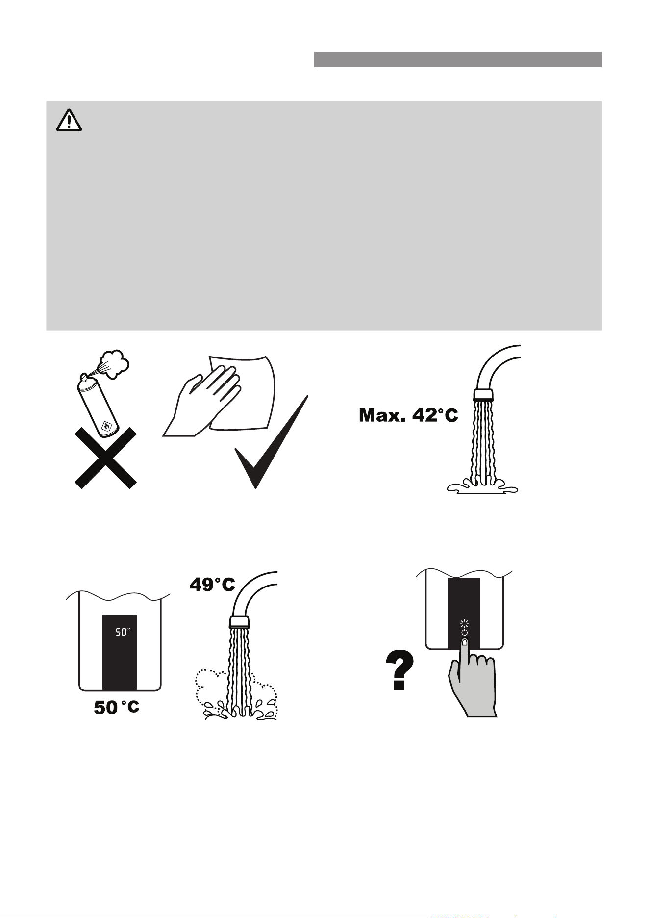
To clean your appliance use a soft damp cloth with a
mild detergent.
DO NOT use solvents!
While hot water outlets are open the set temperature
may be lowered. However, they cannot then be raised
above 42°C.
Depending on the weather conditions and the length
of the pipe between the hot water unit and the
outlet in use, there may be a variation between the
temperatures displayed at the water controller(s) and
the temperature of the water at the outlet.
There is no need to turn the appliance o after use.
The appliance will be on standby mode automatically.
WARNINGS & IMPORTANT INFORMATION
Rinnai 7 ELECTRIC CFWH_OIM - Issue 1
DO NOT push the On/O button on the appliance
when the water heater is on as this will turn o the
water heater.
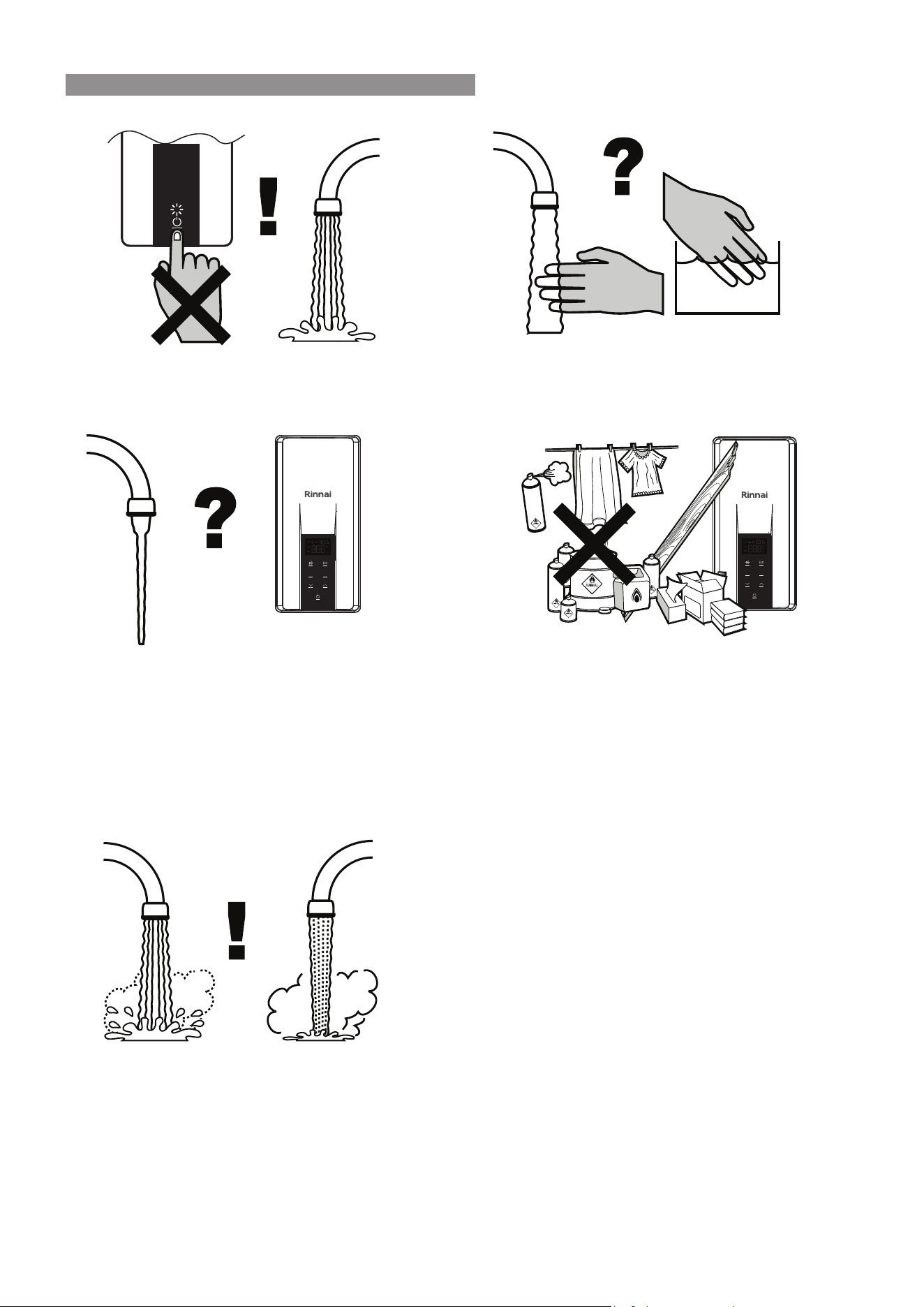
Always check water temperature carefully before use.
Refer to the "SCALD HAZARDS" ON PAGE 5
for important safety information.
OFF!
At low water ows, the hot water unit may extinguish
without warning. Opening the tap further will restart
the heating appliance.
DO NOT Spray aerosols in the vicinity of this appliance
while it is in operation.
DO NOT use or store ammable materials in or near
this appliance.
DO NOT place articles on or against this appliance.
DO NOT modify this appliance.
DO NOT store pool chemicals near this appliance.
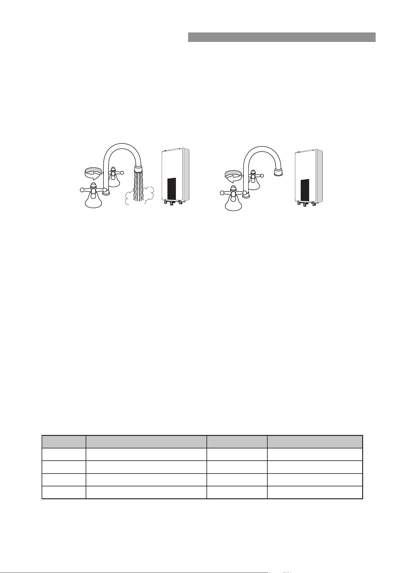
43°C 55°C
The delivered water temperature is controlled
automatically. The water ow will vary depending on
the delivery temperature selected and the ambient
water temperature.
WARNINGS & IMPORTANT INFORMATION
Rinnai 8 ELECTRIC CFWH_OIM - Issue 1
Congratulations on purchasing the latest technology temperature controlled Rinnai electric continuous ow water
heater.
Rinnai electric continuous ow water heater products operate automatically. The opening of any hot water tap
will automatically start the appliance. Once water is owing through the appliance, the heating elements become
energised to heat the water immediately.
The owing water will be supplied up to the maximum temperature that the unit is capable or set to supply. As with
all water heaters, cold water may need to be added to reduce the temperature to the desired level. When the hot
water tap is closed and water ceases to ow through the appliance, the heating elements stop heating automatically.
MAXIMUM DELIVERY TEMPERATURE
Rinnai electric continuous ow water heaters are factory pre-set to various maximum delivery temperatures (50°C
or 60°C) depending on model and their intended application
Temperature Control
This water heater allows precise temperature control by the user. When used correctly, the hot water unit will adjust
to supply at the selected temperature, even when the water ow is varied, or more than one tap is in use.
The temperature control range is 30 - 50 (50°C appliance*), and 30 - 60°C (60°C appliance).
* These appliances deliver water not exceeding 50°C in accordance with AS3498.
FEATURES & BENEFITS
•
The Rinnai electric continuous ow water heater products NEVER RUN OUT of hot water. While suitable
electricity and water supplies are connected, hot water is available whenever hot water taps are open.
•
Built into the main micro-processor is the facility to LIMIT THE MAXIMUM TEMPERATURE of the hot
water supplied. The water temperature may be limited to various values. This is particularly useful when the
hot water unit is installed where young children or the inrm may be using the hot water.
•
The Rinnai electric continuous ow water heater products are COMPACT, saving both oor and wall space.
•
The delivery temperature of hot water is CONSTANTLY MONITORED by BUILT-IN SENSORS.
•
The control panel console lights up automatically when the hot water tap is opened and goes out after 60
seconds when the tap is closed, and is then in standby mode.
Model Description Max Temperature Rated Power*
ECF19I50 Rinnai Electric CFWH 19.4kW 50°C 50°C 19.4kW@415V AC 3 Phase
ECF19I60 Rinnai Electric CFWH 19.4kW 60°C 60°C 19.4kW@415V AC 3 Phase
ECF29I50 Rinnai Electric CFWH 28.5kW 50°C 50°C 28.5kW@415V AC 3 Phase
ECF29I60 Rinnai Electric CFWH 28.5kW 60°C 60°C 28.5kW@415V AC 3 Phase
*See Table 1, page 26 for rated power in New Zealand at 400 V.
HOHOTT
COCOLLDD
ON!ON!
HOHOTT
OFFOFF!!
COCOLLDD
OFF!
ON!
ABOUT YOUR HEATER
Rinnai 9 ELECTRIC CFWH_OIM - Issue 1
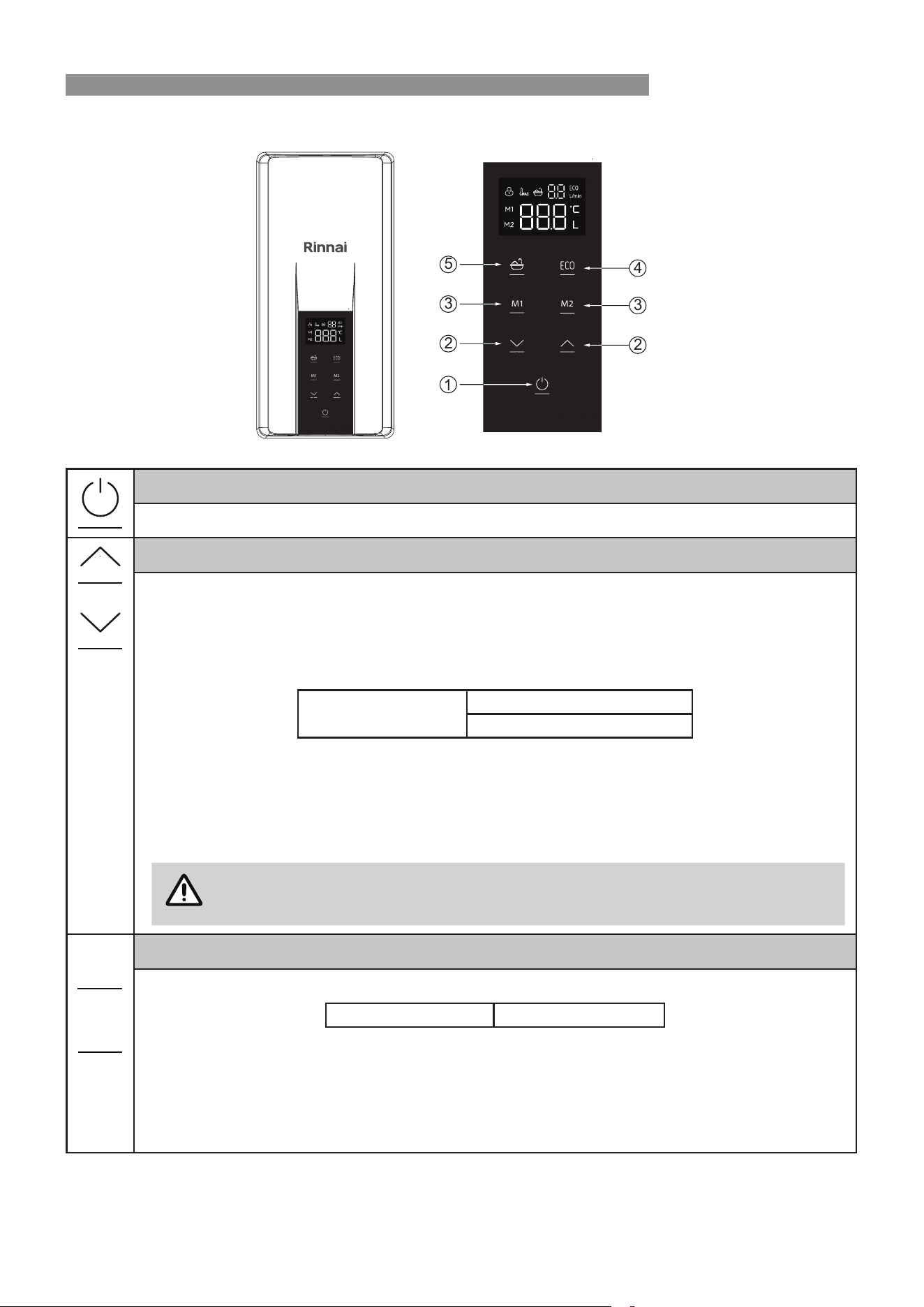
CONTROL PANEL CONSOLE OPERATION
y ON / OFF button
Press the 'ON/OFF' button on the Control Panel to turn the appliance on or o.
x Temperature adjustment buttons
Press the ‘UP’ or ‘Down’ button to adjust the water temperature.
Select the desired temperature using the temperature adjustment ‘UP’ or ‘Down’ button until the
required temperature is displayed on the screen.
To operate the hot water unit, open any hot water tap. It will automatically start the appliance and
provide hot water. The display screen shows the water temperature (°C) and ow rate (L/min)
Temperature range
30~60°C for 60°C appliance
30~50°C for 50°C appliance
For hygiene in sanitary areas such as bathrooms, the suggested temperature should be 37°C ~ 43°C.
The above is a recommendation only, as you may nd higher or lower temperatures more comfortable.
However, maintaining lower temperatures also helps to save energy.
For safety reasons, the set temperature cannot be raised above 43°C until all hot water taps are
closed.
NOTE
While hot water outlets are open, for safety, the temperature CANNOT be raised
above 43°C until all hot water taps are closed.
c M1 / M2 buttons
M1 and M2 are factory preset at temperatures for quick change of set points.
M1 is preset at 38°C M2 is preset at 42°C
Press M1 or M2 to set the appliance to preset mode. To exit the preset mode, press M1 or M2 button
again.
It allows user to adjust / save your M1 or M2 preset temperature. Press and hold M1 or M2 button for 3
seconds, the temperature display on the display panel will ash. Then adjust the temperature set point
by pressing ‘UP’ or ‘Down’ button. Press M1 or M2 button to exit the mode, the selected temperature
will now be set and saved.
1
2
3
5
2
3
4
OPERATION
Rinnai 10 ELECTRIC CFWH_OIM - Issue 1
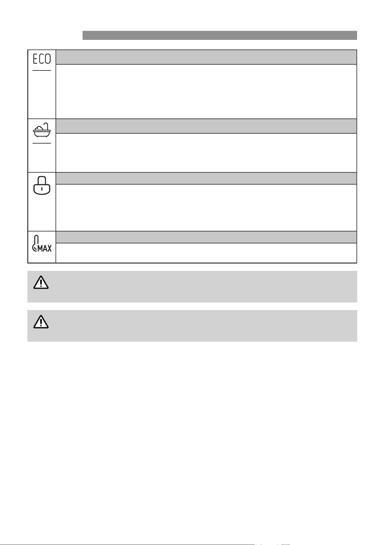
v ECO button
Press the 'ECO' button to set maximum water ow.
In 'ECO' mode the water ow rate will be controlled by the ow control device to the following xed
rates: 6L/min, 7L/min, 8 L/min or 9L/min
Press ECO button to exit 'ECO' mode, the appliance operates automatic water ow control. The water
ow varies automatically depending on the delivery temperature selected and the ambient water
temperature.
b Bath button
This selection allows user to see the accumulated water consumed.
Press 'Bath button' to set appliance to bath mode. The preset temperature and water ow can be set
by pressing the ‘UP’ or ‘Down’ button and 'ECO' button.
To exit the 'Bath mode', press the 'Bath button' again.
Lock
The Lock function is designed to prevent accidental operation and small children from altering the
heater settings.
Press and hold ‘UP’ and ‘Down’ button simultaneously until the padlock symbol is displayed. All control
functions are now locked and none of the buttons on the control will work.
To deactivate the lock, repeat locking step above to return the normal operation.
TMax
This Tmax display is for 50°C compliant models maximum delivery temperature adjustment from the
‘Factory Set’ value. See "50°C Compliant Models" on page 23 for more detailed information.
NOTE
During operation, when using any of the soft-touch buttons, the display reaches maximum
brightness. When there is no operation after 10 seconds the display will dim, and the display will
cease illuminating after 60 seconds. To wake the screen, press any button on the Control panel.
IMPORTANT
When the water heater re-starts from a power outage or is switched o, it will remain at the
previous saved setting.
OPERATION
Rinnai 11 ELECTRIC CFWH_OIM - Issue 1
TURNING WATER HEATER ‘OFF’
If the water heater is not going to be used for only a few days, we suggest you leave it switched on. For longer
periods of inactivity, turn o both the water supply and power to the unit. This will ensure no risk of water freezing
in the unit in very cold conditions. If it is necessary to switch o the water heater, the switch is usually marked and
located in the electricity meter box of the building. Then close the cold water isolation valve at the inlet to the water
heater. Opening the hot outlets may cause the heater to drain.
TURNING WATER HEATER ‘ON’
WARNING
DO NOT switch on the electric power supply until the water heater is lled completely with water.
Always check that hot water is running freely from the hot water outlets before switching the
heater on.
Switch on the electric supply to the water heater. The switch is usually marked and located in the electricity meter
box of the building. Water heating will now occur as required.
CLEANING AND INSPECTION
It is recommended that you clean or inspect your appliance every six months or more regularly as required.
Switch o the electrical supply prior to carrying out cleaning and inspection. Use a non-abrasive damp cloth and
mild detergent for cleaning appliance enclosure. DO NOT use alcohol, solvents or abrasive cleaning substances.
Inspect around the enclosure for insects, insect nests and spider webs which should be removed and cleaned out
before powering and operating the unit. We recommend periodic pest control treatment to address this risk.
WARNING
There are no consumer serviceable parts inside the appliance, access covers MUST only be
removed by an authorised person.
Visually inspect power and water connections for damage.
DRAINING
WARNING
Draining MUST be carried out by a qualied person.
Water may be HOT during draining.
Drain the water heater as follows:
1. Isolate or turn ‘OFF’ the water heater at the electricity supply.
2. Close the cold water isolation valve at the inlet to the water heater.
3. Open a hot tap. When water stops owing, close the hot tap.
4. Loosen Brass Tee ttings of the inlet and outlet connections. Collect water from the water heater by using a
suitable container.
MAINTENANCE

Rinnai 12 ELECTRIC CFWH_OIM - Issue 1
ERROR CODES
Your Rinnai electric continuous ow water heater has a self diagnostic capability. If a fault occurs, an Error Code
will ash on the display of touch screen on the console of the water heater. This assists with diagnosing the fault.
Please quote the code displayed when requesting service and warranty support.
Code Description Remedy
E1
Sensor failure Service Call.
E2
Outlet temperature exceeds 75°C Service Call.
E3
Outlet temperature exceeds 85°C Service Call.
EC
Communication error between PCB boards Service Call.
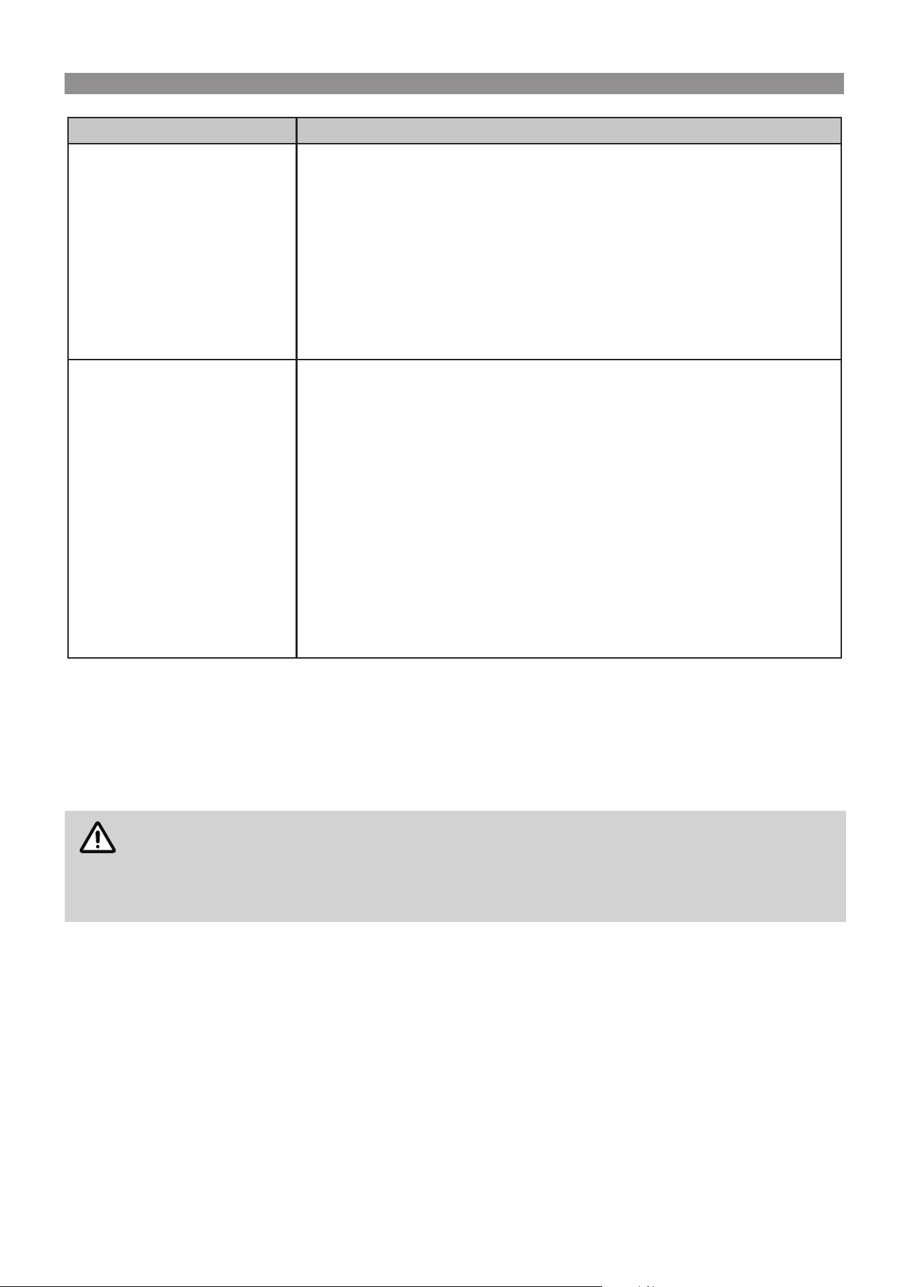
SAVE A SERVICE CALL
Check the items below before requesting a service call. Service and parts charges may be incurred where it is
found that there is no fault with the water heater and the issue is related to the plumbing installation or is due to the
failure of water or electric supplies.
Description Possible Remedy
No display on the water heater
• Check the water heater switched on at the power supply. The switch is
usually marked and located in the electricity meter box of the building.
• Check power available.
• Check the water heater is turned on at the console.
• Press any button on the control panel console or turn on a hot water tap.
No water from the hot tap
• Check the cold water supply to the water heater. Ensure cold water isolation
valve is fully open.
• Check lter for blockages by an authorised person. If not resolved, book a
Service call.
Cold water from the hot tap
• Check that power is available.
• Check that the water heater is switched on at the power supply.
• Check the water heater is turned on.
• Check the temperature setting on Control panel console. if not set properly,
adjust temperature by pressing ‘Up’ or ‘Down’ buttons.
• Close the hot tap, wait 10 seconds then open the hot tap again.
• Check that the hot tap is open enough.
• The water heater will not turn on if the ow rate is less than 2.5 l/min.
Water is too hot or not hot
enough
• Check the temperature setting on the Control panel console. If not set
correctly, adjust the temperature by pressing ‘Up’ or ‘Down’ buttons.
• A 50°C water heater can have the delivery temperature adjusted by a
plumber to account for temperature losses in the hot pipes or to limit the
maximum delivery temperature. Service call.
• You may not have the correct size water heater for your requirements.
Service call.
TROUBLE SHOOTING
Rinnai 13 ELECTRIC CFWH_OIM - Issue 1
Description Possible Remedy
Not enough water ow
• Is more water being used than the water heater can heat adequately?
• The water ow varies automatically depending on the delivery temperature
selected and the ambient water temperature. If more water taps are open
or the ambient temperature is colder, the water heater will reduce the water
ow automatically to maintain water temperature.
• Is the water pressure adequate to deliver the desired ow rate? The
specications table on page 26 indicates the minimum and maximum
water supply pressures and the minimum operating water ow rate in L/min.
• The water heater is tted with a lter to prevent the system from blockages
due to debris. Have a plumber inspect the lter.
Temperature uctuates
• Too many taps are in use at the same time. This may cause either a
reduction in ow rate per tap or temperature uctuations from the taps.
• Are there several hot taps open, or are appliances such as a dishwasher or
washing machine in use at the same time?
• Check the ow of hot water from each tap to see if one or more outlets are
using more water than you think.
• The supply of consistent hot water temperature is dependent on the size of
the water heater, the geographic location and the season. Have a plumber
install a ow control valve to each shower outlet, basin and sink to reduce
water usage.
• The specications table on page 26 indicates the ow rate required, and
the maximum ow rate capable, from each model water heater at various
cold water inlet temperatures to provide hot water at 40⁰C to a 9L/min limited
shower rose.
SERVICE
This Water Heater does not contain user serviceable parts and MUST only be serviced and repaired by an
authorised person.
Rinnai has a Service and Spare Parts network with personnel who are fully trained and equipped to give the best
service on your Rinnai appliance. If your appliance requires service, please call our National Help Line or the Hot
Water Service Line (contact numbers for which are on the back cover of this manual).
NOTE
When making a service enquiry, having both the model and serial numbers available, will help our
sta quickly identify your appliance and better attend to your needs.
This information should have been copied to the "Installation Record" on page 25 by your
installer. However if this is not the case, the information can also be found on the data plate
located on the left hand side of the appliance.
For safe and ecient operation and prevention of premature deterioration, Rinnai advises and recommends that
this appliance be serviced every 12 months by an authorised service technician.

Rinnai 14 ELECTRIC CFWH_OIM - Issue 1
Operation Table of Contents 3
Installation 15
Regulations ������������������������������������������������������������������������������������������������������������������������������������������������������������������������ 15
Water Supply ���������������������������������������������������������������������������������������������������������������������������������������������������������������������� 15
Water Quality ................................................................................................................................................................... 15
Appliance Location and Minimum Clearances ��������������������������������������������������������������������������������������������������������������� 16
Mounting of Appliance ������������������������������������������������������������������������������������������������������������������������������������������������������ 17
Service Connection Points ���������������������������������������������������������������������������������������������������������������������������������������������� 18
Installation Conguration ������������������������������������������������������������������������������������������������������������������������������������������������� 18
Plumbing Connections to the Water Heater �������������������������������������������������������������������������������������������������������������������� 19
Plumbing Connections from the Bottom of the Appliance �������������������������������������������������������������������������������������������� 20
Electrical Supply 21
Electrical Connection �������������������������������������������������������������������������������������������������������������������������������������������������������� 21
Wiring 22
Appliance Wiring Diagram ������������������������������������������������������������������������������������������������������������������������������������������������ 22
Commissioning 23
To ll & turn ‘ON’ the Water Heater ���������������������������������������������������������������������������������������������������������������������������������� 23
To turn ‘OFF’ the Water Heater ����������������������������������������������������������������������������������������������������������������������������������������� 23
Delivery Temperature �������������������������������������������������������������������������������������������������������������������������������������������������������� 23
50°C Compliant Models .................................................................................................................................................. 23
For all Other Models ....................................................................................................................................................... 24
Installation Record ������������������������������������������������������������������������������������������������������������������������������������������������������������ 25
Specications 26
Table 1. Technical Specications ������������������������������������������������������������������������������������������������������������������������������������� 26
Contacts 28
INSTALLATION TABLE OF CONTENTS

Rinnai 15 ELECTRIC CFWH_OIM - Issue 1
WARNING
INSTALLATION, SERVICE AND REMOVAL MUST BE BY AN APPROPRIATELY LICENSED
TRADESPERSON ONLY (THIS NEEDS AN ELECTRICIAN AND A PLUMBER).
This appliance must be permanently connected to xed wiring.
If the electrical conduit to the water heater is damaged, it MUST be replaced by a qualied person
in order to avoid a hazard.
Removal of the access covers of the water heater will expose 415V 3 phase electrical supply.
Access covers MUST ONLY be removed by an authorised person.
The resistivity of the water supply must not be less than 800 Ω.cm.
This appliance MUST be earthed in accordance with the Wiring Rules.
This appliance is NOT suitable for use as a spa or swimming pool heater.
This appliance is NOT to be used for a portable water supply.
DO NOT operate this system before reading the manufacturer's instructions.
DO NOT modify the electrical wiring of this appliance. If the control power wiring is damaged
or deteriorated then it must be replaced by an Authorised Person. Failure to do so may result in
electric shock, re, serious injury or product failure.
REGULATIONS
This appliance MUST be installed in accordance with:
•
Manufacturer's installation instructions
•
Current AS/NZS 3000 Wiring Rules
•
Plumbing Code of Australia (PCA) or New Zealand Building Code
•
All local regulations and municipal building codes including local OH&S requirements
WATER SUPPLY
The appliance is intended to be permanently connected to a reticulated public water supply.
The maximum water supply pressure for the water heater is 850kPa. An approved Pressure Limiting Valve (PLV)
may be required.
The minimum water supply pressure for the water heater is 100kPa. The water heater will operate at lower
pressures but will not achieve the rated ow.
Minimum ow rate to initiate heating is 2.5L/min.
Water Quality
Water chemistry and impurity limits are detailed as below. Most metropolitan water supplies fall within the
requirements. Water quality from bore wells is generally unsuitable. If you are unsure about your local water quality,
contact your water authority. If sludge or foreign matter is present in the water supply, a suitable lter or strainer is
required in the water supply to the water heater to prevent unwarranted damage and loss of performance.
Scaling water is dened as having a total hardness in excess of 200 mg/litre (expressed as calcium carbonate) or
a Saturation Index in excess of +0.4. Areas that have a scaling water supply include South Australia and Western
Australia. In a scaling water supply, calcium carbonate and possibly other compounds are deposited out of the
water onto any hot metallic surfaces and form a scale.
Check with your local regulatory authorities as they may require an Expansion Control Valve (ECV) to be tted. If
required, in areas of poor quality or scaling water supply, an ECV should be tted in the cold water line between
the non return valve and the connection to the water heater to protect the water heater. The ECV is to be supplied
and tted by the installer.
INSTALLATION
Rinnai 16 ELECTRIC CFWH_OIM - Issue 1
IMPORTANT
Where the site water chemistry may not meet these limits, site sample water laboratory testing
is required to demonstrate suitability. Where the actual chemistry or impurities are outside these
specied limits, suitable water treatment MUST be implemented and maintained to protect the
water heater and not void its warranties.
Electric Continuous Flow Heater Water chemistry and impurity level limits
Chlorides –
mg/L
pH Saturation
Index
Total Dissolved
Solids Range -
mg/L
Water Resistivity
Range - Ω.cm @
20°C
Water Conductivity
Range - µS/cm @
20°C
≤ 200 5.5 to 9.5
-1.0 to +0.4
@65°C
≤875 ≥800 ≤1250
Water hardness and pH
In a high chloride water supply, calcium carbonate and possibly other compounds deposited out of the water, may
corrode the heating element and other components and cause them to fail.
IMPORTANT
Rinnai warranty DOES NOT apply to the water heater where the water supply chloride level
exceeds 200 mg/L.
pH is a measure of whether the water is alkaline or acid. In an acidic or very alkaline water supply, the water can
attack the heating element and other components and other parts and cause them to fail.
IMPORTANT
Rinnai warranty DOES NOT apply to the water heater where the water supply pH is less than 5.5
or greater than 9.5.
Saturation Index
The saturation index is used as a measure of the water’s corrosive or scaling properties. In a corrosive water
supply, the water can attack copper parts and cause them to fail.
IMPORTANT
Rinnai warranty DOES NOT apply to the water heater where water supply saturation index
exceeds +0.40 or less than -1.0 @65°C.
Total Dissolved Solids (TDS), Resistivity and Conductivity
The resistivity of the water must be greater than 800 Ω.cm for the water heater to operate correctly.
Resistivity lower than this may cause residual current devices (RCD) to trip.
IMPORTANT
Rinnai warranty DOES NOT apply to the water heater where water supply TDS more than 875mg/L,
or Water Resistivity Ω.cm less than 800 Ω.cm, or Water Conductivity more than 1250 µS/cm.
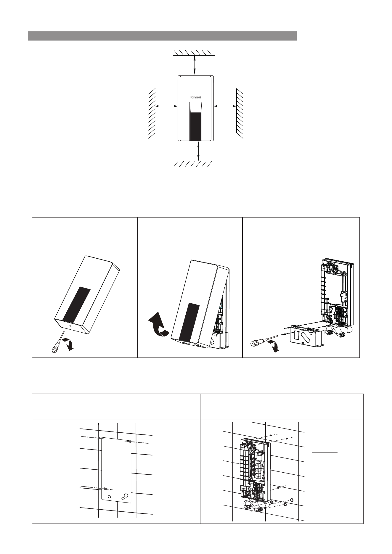
APPLIANCE LOCATION AND MINIMUM CLEARANCES
This appliance is designed for ‘Indoor’ installation only.
The water heater should be placed as close as practicable to the most frequently used outlet point or points. This
will usually be the kitchen tap.
IMPORTANT
• Ensure the appliance is NOT installed in locations where freezing can occur.
• Ensure the appliance is located away from heat or steam.
• Ensure the appliance is located so it can be accessed for service and replacement.
• Select a location where the appliance can be securely mounted.
• The minimum clearance shown below MUST be maintained.
INSTALLATION
Rinnai 17 ELECTRIC CFWH_OIM - Issue 1
The wall or structure on which the units are to be mounted MUST be capable of supporting these weights and the
associated pipe-work when lled. Refer to "Specications" on page 26 for specic model weights.
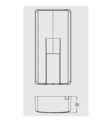
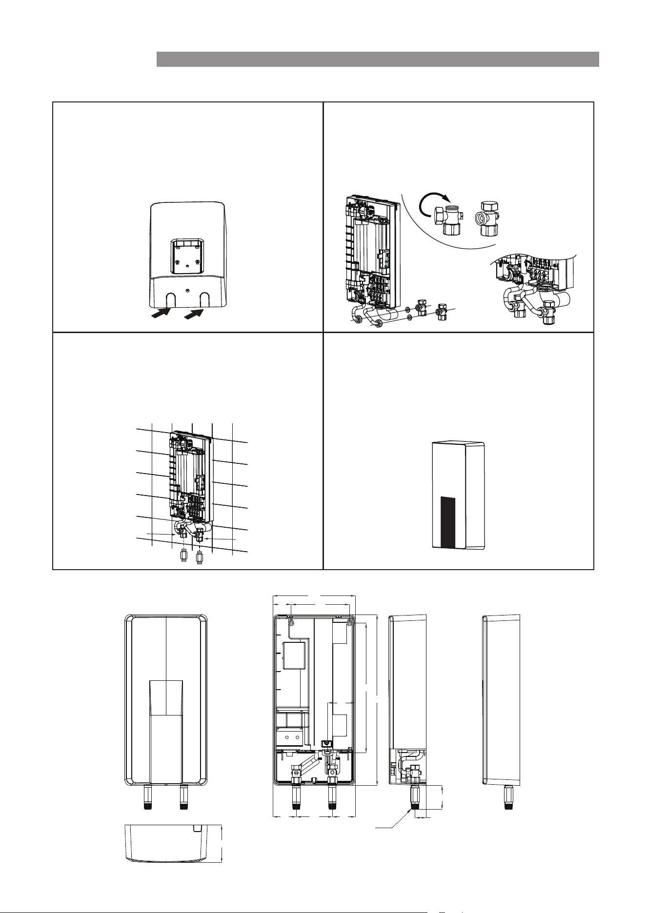
MOUNTING OF APPLIANCE
•
Remove the front cover.
Remove the screw located
underneath the appliance.
Carefully disconnect the display
board cable and remove the front
cover. NOTE: Factory default,
the cable is disconnected.
Remove two screws and unclip
the grey cover at the bottom of the
heater.
•
Prepare the power cable from the walls.
•
Determine electrical connection and plumbing connection method and location.(Refer to "Plumbing
Connections to the Water Heater" on page 19 and "Electrical Connection" on page 21).
Use the supplied installation mounting template
to mark the 3 mounting hole positions (below), and
location of plumbings and electrical connections.
Fix the water heater onto the wall using appropriate
xing screws suitable for the mounted surface
material and able to support this unit.
NOTE:
Use pan
head
screws
(M4) with
washers
>100mm>100mm
>90mm
>200mm
INSTALLATION
Rinnai 18 ELECTRIC CFWH_OIM - Issue 1
SERVICE CONNECTION POINTS
Refer to "Specications" on page 26 for model specic connection / tting dimension details.
An Approved full ow isolation valve and disconnection union MUST be tted to the cold water. A non return valve
is not required on the water inlet unless required by local regulations.
Isolation Valves MUST NOT be tted directly to the appliance.
If may be necessary to t a temperature limiting device for delivery to areas used primarily for the purposes of
personal hygiene.
Clear all pipe work before connection and purge cold water supply lines to remove air and swarf before nal
connection of the appliance. Swarf in the water supplies may cause damage.
WARNING
If olive compression ttings are used for connections the olives MUST be metallic such as brass
or copper. Only approved thread sealing tape or sealant should be used.
Sealant MUST NOT be allowed in the waterways of pipework or ttings. Excess sealant may be
carried into the water heater. It will damage components and block the internal lter.
IMPORTANT
Water pipe sizing and layout MUST be performed in accordance with AS/NZS 3500. All hot water
pipe-work MUST be insulated to optimise performance and energy eciency.
This appliance is intended to be permanently connected to the water mains and not connected
by a hose-set.
Ensure all pipe connections be correctly aligned.
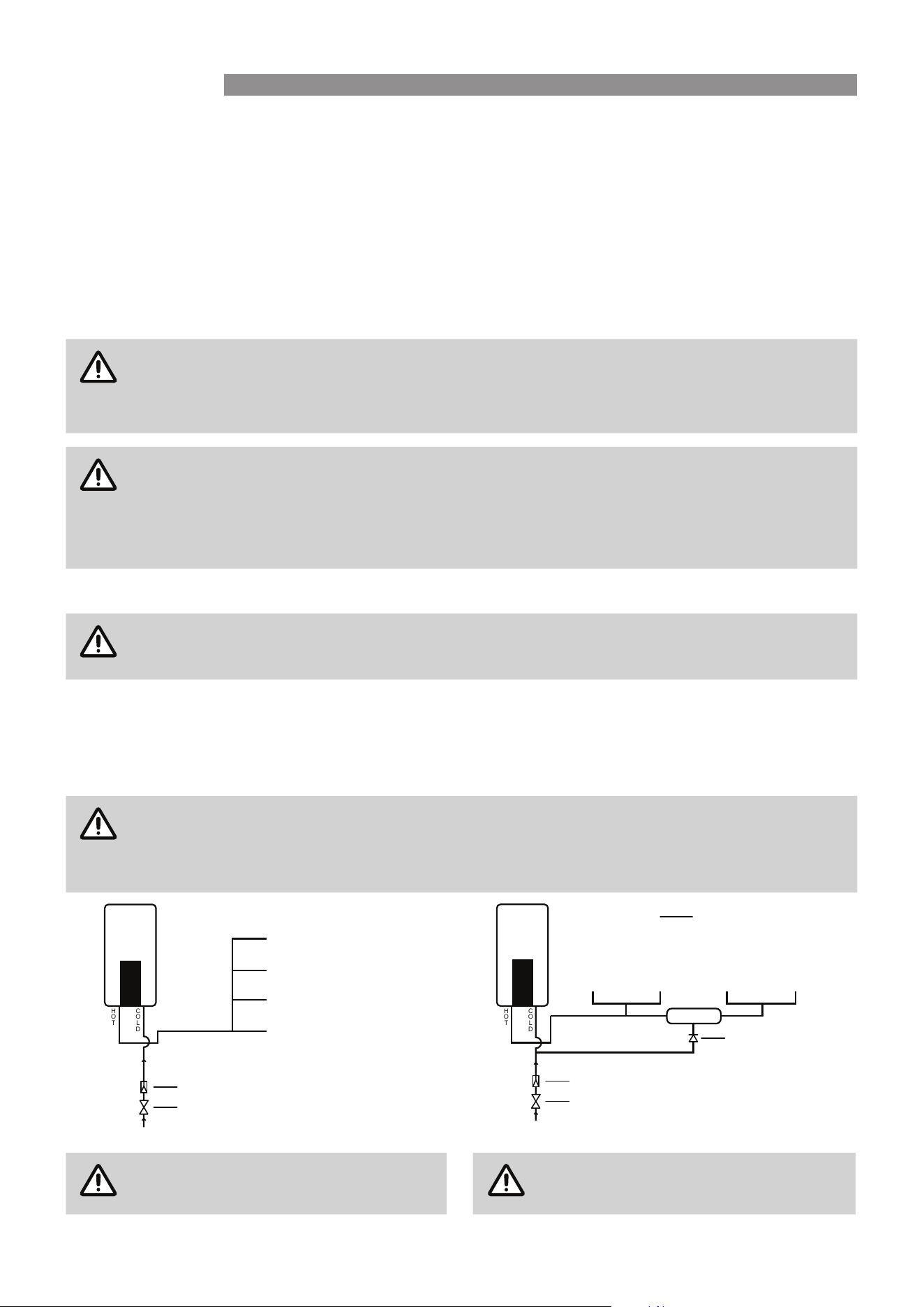
INSTALLATION CONFIGURATION
WARNING
This appliance may deliver water at high temperature. Refer to the Plumbing Code of Australia
(PCA), local requirements and installation instructions to determine if additional delivery
temperature control is required.
If the appliance is marked to state that it delivers water not exceeding 50°C, local regulations may permit installation
without a Temperature Limiting Device. Installations without a Temperature Limiting Device are shown in Diagram
1 below. If you are unsure about your local regulations contact your regulatory authority. If the appliance is NOT
marked to state that it delivers water not exceeding 50°C, or your local regulations require installation with a
Temperature Limiting Device then install the appliance in accordance with Diagram 2 below.
IMPORTANT
If the appliance is to deliver water primarily for the purposes of personal hygiene in an early
childhood centre, primary or secondary school, nursing home or a similar facility for the care of
young, aged, sick or disabled persons as dened in AS/NZ 3500 a Temperature Limiting Device
(TLD), such as a Tempering Valve may be required even if the appliance is set to 50º C or less.
50º C
KITCHEN
LAUNDRY
BATHROOM
ENSUITE
H
OT
C
O
LD
Diagram 1 : 50°C Appliance
COLD SUPPLY
Isolating Valve
PLV (if required)
KITCHEN LAUNDRY BATHROOM ENSUITE
TLD
H
OT
C
O
LD
Diagram 2 : NOT a 50°C Appliance
COLD SUPPLY
Isolating Valve
PLV (if required)
Non-return Valve
NOTE
Minimum length of pipe from hot outlet
to nearest hot water tap 1 metre.
NOTE
TLD = Temperature Limiting Device.
INSTALLATION
Rinnai 19 ELECTRIC CFWH_OIM - Issue 1
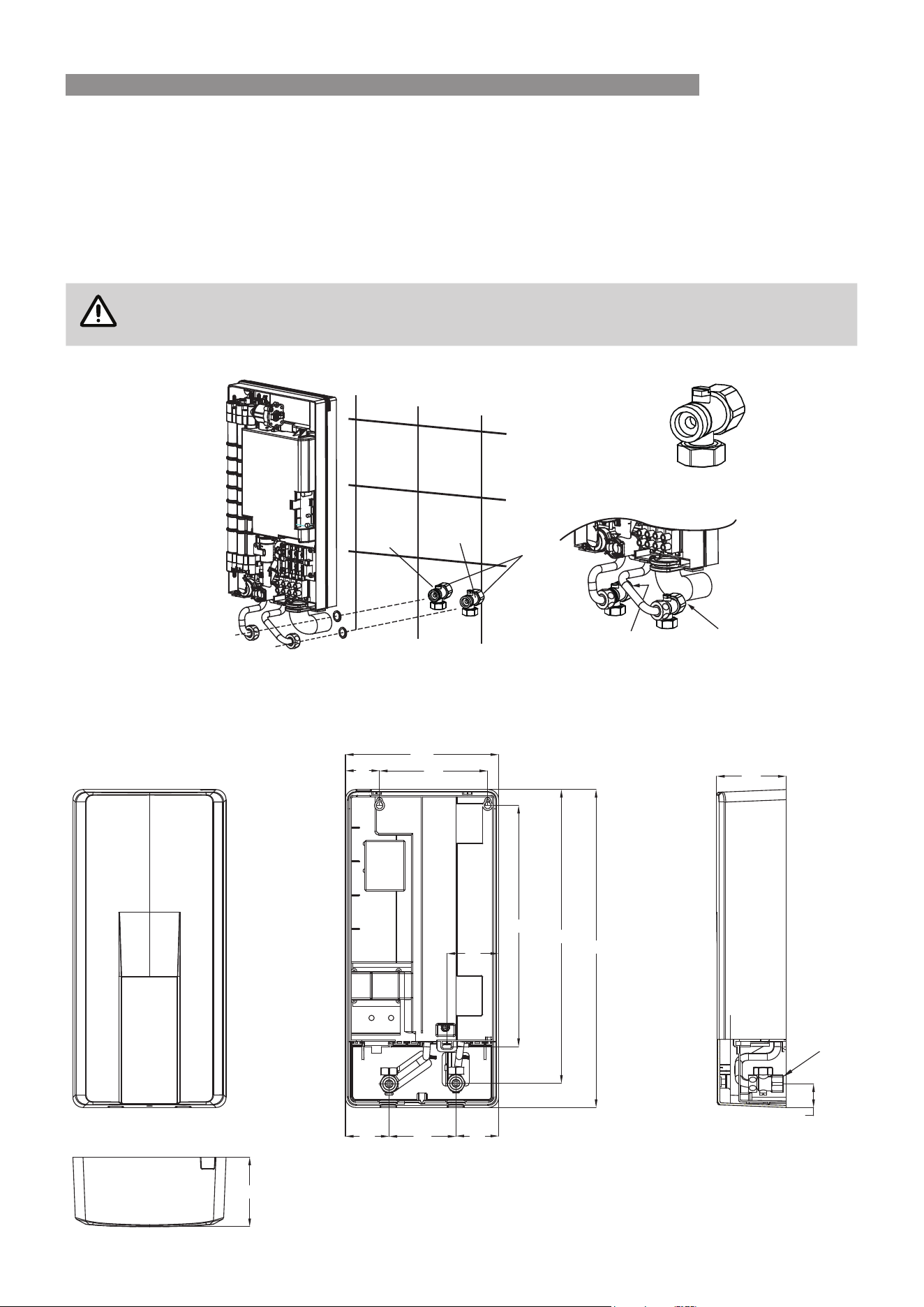
PLUMBING CONNECTIONS TO THE WATER HEATER
Connections through the walls or back of the appliance
•
The appliance is supplied with Brass Tee ttings.
•
Fit a rubber washer in the cold and hot Brass Tee ttings.
•
Connect to the cold and hot water supplies as shown below.
•
Do not over-tighten connections.
IMPORTANT
Ensure the cold inlet Brass Tee tting fully opens the auxiliary shut o feature. An approved
isolating valve is still required.
G1/2’
Inlet
Outlet
Hot outlet Cold inlet
Cold inlet
Brass Tee
fitting
Dimensional Drawing
471
227
160
357
51
76
100
65
63
103
435
35
103
G1/2’
All measurements are in mm unless otherwise specified
INSTALLATION
Rinnai 20 ELECTRIC CFWH_OIM - Issue 1
PLUMBING CONNECTIONS FROM THE BOTTOM OF THE APPLIANCE
•
For this installation, it will be required to remove
the pipe knock-out from the bottom of the cover.
•
Using suitable tools, gently cut or break out the
knock-out.
•
Clean up any burrs if required.
•
Fit and tighten the cap onto the unused outlet as
shown below. Make sure the rubber washers have
been tted.
•
Let the opening facing down.
•
Use the straight adapters provided for inlet and
outlets as shown.
•
Connect to the cold and hot water supplies to the
R ½’ male straight adapters with rubber washers.
•
Do not over-tighten connections.
•
Re-position the rubber conduit in the slot.
•
Re-position the grey cover and t it with 2 screws.
•
Re-connect the communication cable to the main
PCB.
•
Cover and secure with screw.
Hot outlet
Cold inlet
Dimensional Drawing
All measurements are in mm unless otherwise specified
471
227
100
65 63
160
357
51
76
30
66
103
R1/2
INSTALLATION
Rinnai 21 ELECTRIC CFWH_OIM - Issue 1
WARNING
This appliance MUST be installed, maintained and removed by Authorised Persons in accordance
with AS/NZS 3000 (Wiring Rules) and all other relevant local regulations and municipal building
codes including OH&S requirements.
Ensure the circuit is to be RCD protected.
Ensure electric wiring is installed properly. Improper installation may cause malfunction, re, or
electric shock.
The appliance MUST be earthed in accordance with local electrical requirements.
This appliance MUST connect to an independent, fused, AC 380-415V~ 3 phase 50HZ power supply with an
isolating switch installed at the switch board. It MUST eectively isolate all active supply conductors from the
circuit, and means for disconnection MUST be incorporated in the xed wiring in accordance with the Wiring Rules.
WARNING
The water heater MUST be lled with water prior to connection to the power supply.
Ensure the premises wiring to the system is capable of withstanding the system electrical load.
Electrical Specications
Model ECF19I50 ECF19I60 ECF29I50 ECF29I60
Rated Voltage (VAC) 380 400 415 380 400 415 380 400 415 380 400 415
Rated Power Rate (kW) 16.2 18 19.4 16.2 18 19.4 24.4 27 28.5 24.4 27 28.5
Rated Current (A) 24.5 26 26.9 24.5 26 26.9 37 39.1 39.6 37 39.1 39.6
Phases/Frequency 3 phase 50Hz
Water Resistivity (Ω.cm) ≥ 800
Conductivity (μS/cm) ≤ 1250
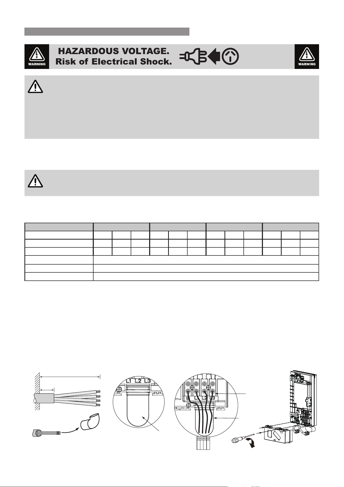
ELECTRICAL CONNECTION
1. Prepare the power cable.
2. Open the appliance. Refer to more detailed instructions on page 17
3. Inset 3 phase power cable through rubber conduit.
4. Connect power cable to the main terminal at earth, L1, L2 and L3 as shown.
5. Ensure the rubber conduit is in the slot.
6. Re-position the grey cover and t it with 2 screws.
7. Re-connect the communication cable to Main PCB.
8. Cover and secure with screw.
Step 1 Step 2
(Refer to page 17)
Step 3
Step 4 & 5
Step 6
Power cable
entry conduit
Power cable
connector
Power cable
entry hose
EARTH
L1
L2
L3
150 mm
≥30mm
Isolate all
sources of supply
prior to servicing
ELECTRICAL SUPPLY
Rinnai 22 ELECTRIC CFWH_OIM - Issue 1
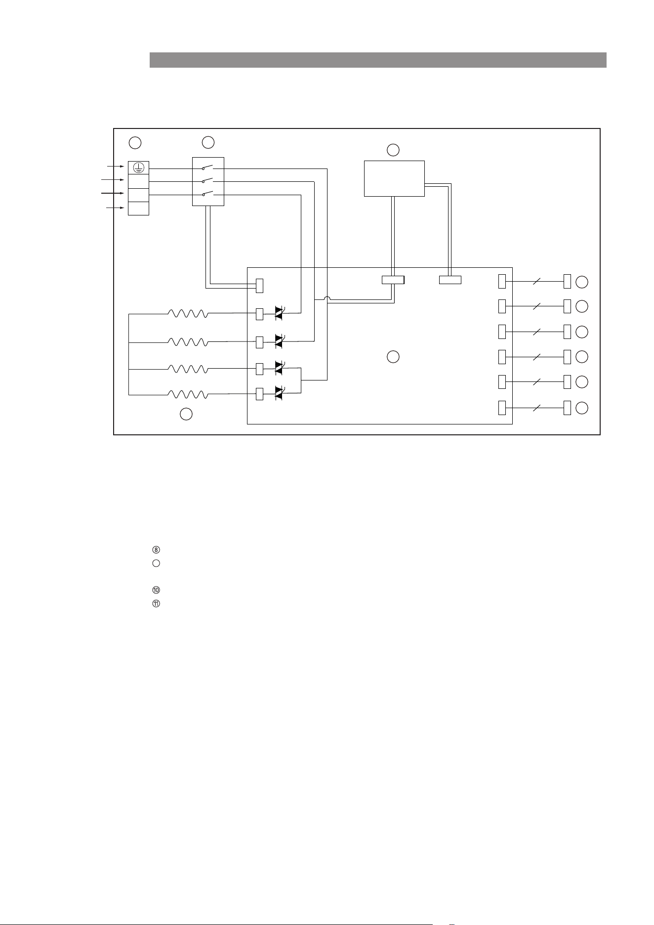
APPLIANCE WIRING DIAGRAM
1
2
3
4
5
6
8
9
10
7
L1
L2
L3
4
2
2
3
4
8
Terminal Block
Safety Contactor
Heating Element
Main PCB
Control Board
Over-Pressure Switch
Thermal Cut-Out
Water Flow Sensor
Cold Water Inlet Temp Sensor /
Hot Water Outlet Temp Sensor
Water Flow Control Device
Transformer
11
9
Earth
L
L
L
AC415V~ 3 phase 50HZ Power Supply
WIRING
Rinnai 23 ELECTRIC CFWH_OIM - Issue 1
WARNING
Commissioning MUST be carried out by an authorised person.
DO NOT switch on the electric power supply until the water heater is lled completely with water.
TO FILL & TURN ‘ON’ THE WATER HEATER
Before nal connection of the water heater purge all hot water and cold water supply lines. Debris or swarf in water
supplies may cause damage.
1. Open all hot water taps in the building, including the shower.
2. Open the cold water isolation valve to water heater. Air will now be forced out of the taps.
3. Close each tap when water runs freely without air bubbles.
4. Check all plumbing connections and pipe work for water leaks.
5. Turn on the water heater at the electric power supply.
6. Open hot water tap(s), and water heater will operate automatically
7. Conrm the hot water delivery temperature(s) using a thermometer. Refer to the section 'Delivery Temperature'
below for more details.
8. If required, adjust temperature as per operation instruction.
IMPORTANT
The appliance can adjust water ow automatically to achieve preset temperature, you may notice
the water heater reduce water ow rate. If required, adjust the preset outlet temperature setting
of the water heater.
TO TURN ‘OFF’ THE WATER HEATER
It may be necessary to turn o a water heater after installation and commissioning, for example during building
activities or if the premises are vacant.
1. Turn 'OFF' the water heater using the Control Panel Console and switch o the power at the electricity supply.
2. Close the cold water isolation valve at the inlet to the water heater.
Finally, explain to the householder the functions and operation of the water heater. Ensure the "Installation Record"
on page 25 is completed and that this manual is returned to the customer.
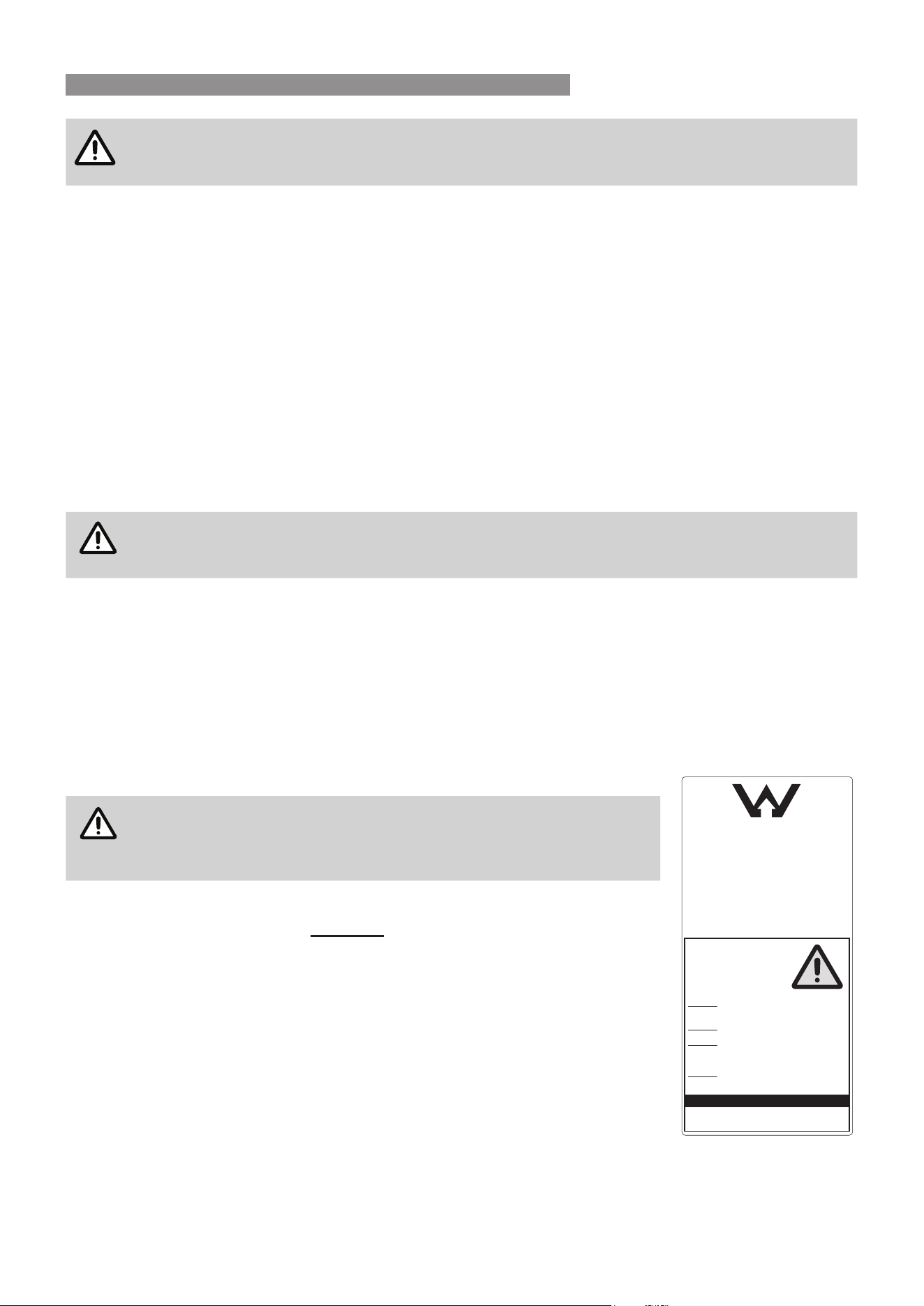
DELIVERY TEMPERATURE
NOTE
'50°C compliant' appliances have labelling applied to the left hand side
panel (as shown), if this label is not evident, then the appliance is NOT
'50°C compliant'. '50°C compliant' labelling on to the front cover alone
does NOT make the appliance '50°C compliant'.
50°C Compliant Models
"50°C Compliant" appliances are factory set to deliver a maximum temperature not
exceeding 50°C. For ne tuning they have an incremental adjustment mechanism
that allows the installer to increase the appliance delivery temperature incrementally
from the 'Factory Set’ value to temperatures slightly exceeding 50°C. This is intended
to enable compensation for temperature losses in the pipe-work between the water
heater and any outlets and achieve the required temperature at the outlet.
1. Carry out installation of the appliance in accordance with the Operation/Installation
manual supplied with the appliance.
2. Measure the maximum hot water temperature from the sanitary xture used
primarily for the purposes of personal hygiene that is closest to the water heater
(for example, a shower outlet in the bathroom closest to the water heater) as
follows:
(i) Set the maximum temperature (this should be 50°C).
(ii) Open the hot tap to the outlet to achieve maximum ow rate (ensure the cold tap to this outlet remains
shut).
Lead Free
This Appliance complies
with current AS 3498
LIC. WM-032245
THIS APPLIANCE DELIVERS WATER NOT
EXCEEDING 50⁰C IN ACCORDANCE WITH AS3498.
REFER TO AS/NZS 3500.4 LOCAL REQUIREMENTS
AND INSTALLATION INSTRUCTIONS TO
DETERMINE IF ADDITIONAL DELIVERY
TEMPERATURE CONTROL IS REQUIRED.
Minimum length of pipe from outlet of water heater to
nearest hot water tap must be 1 metre.
CUSTOMER SERVICE ON THIS APPLIANCE
AUSTRALIA 1300 555 545
SUITABLE ONLY FOR INDOOR INSTALLATION
BEFORE READING THE
WARNING
For continued safety of this
appliance it MUST be installed,
operated and maintained in
accordance with the
manufacturers' instructions.
DO NOT OPERATE THIS APPLIANCE
INSTRUCTION BOOKLET.
DO NOT PLACE ARTICLES ON OR AGAINST
THIS APPLIANCE.
DO NOT STORE CHEMICALS OR
FLAMMABLE MATERIALS, OR
SPRAY AEROSOLS NEAR THIS
APPLIANCE.
DO NOT OPERATE WITH PANELS, COVERS
OR GUARDS REMOVED FROM
THIS APPLIANCE.
COMMISSIONING
Rinnai 24 ELECTRIC CFWH_OIM - Issue 1
(iii) Let the water run for a short period to allow ow rate and temperature to stabilise.
(iv) Measure the stabilised hot water temperature.
3. If the temperature in step (2) is less than 50°C, perform delivery temperature adjustment to increase the
delivery temperature in accordance with the "50°C Compliant Appliances Guidance Notes" below. If the
temperature in step (2) equals 50°C no adjustment is necessary.
50°C Compliant Appliances Guidance Notes
(a) The greater the temperature loss from pipework between the water heater and outlets, the lower the
delivery temperature of water owing through outlets.
(b) The temperature loss from pipework between the water heater and outlets is aected by pipe length,
ow rate and seasonal variations in ambient air and water temperatures.
(c) Temperature loss is typically lower at shorter pipe lengths and higher ow rates. This is taken into
consideration in the operating and measurement parameters specied in procedure Step 2 above.
(d) For a given installation, temperature loss is typically greatest in winter when ambient air and water
temperatures are lowest. Conversely, temperature loss is typically lowest in summer when these ambient
temperatures are highest. It follows that the delivery temperature of water owing through outlets is
typically higher in summer than it is in winter. The installer is to take into consideration the eects of
these seasonal variations in ambient temperatures when carrying out temperature adjustments.
4. After carrying out delivery temperature adjustment re-conrm the maximum hot water temperature from ALL
outlets primarily used for the purposes of personal hygiene (for example, all bathroom shower and basin
taps). In accordance with Step 2 above.
Procedure
•
Turn 'OFF' the water heater on the Control Panel Console and switch o the power at the electricity supply.
•
Open the front cover by removing the screw from the bottom.
•
Hold the front cover while the display board cable is connected.
•
Adjust the Dipswitch as required (refer to Dipswitch settings below).
•
Replace cover
•
Turn on Appliance
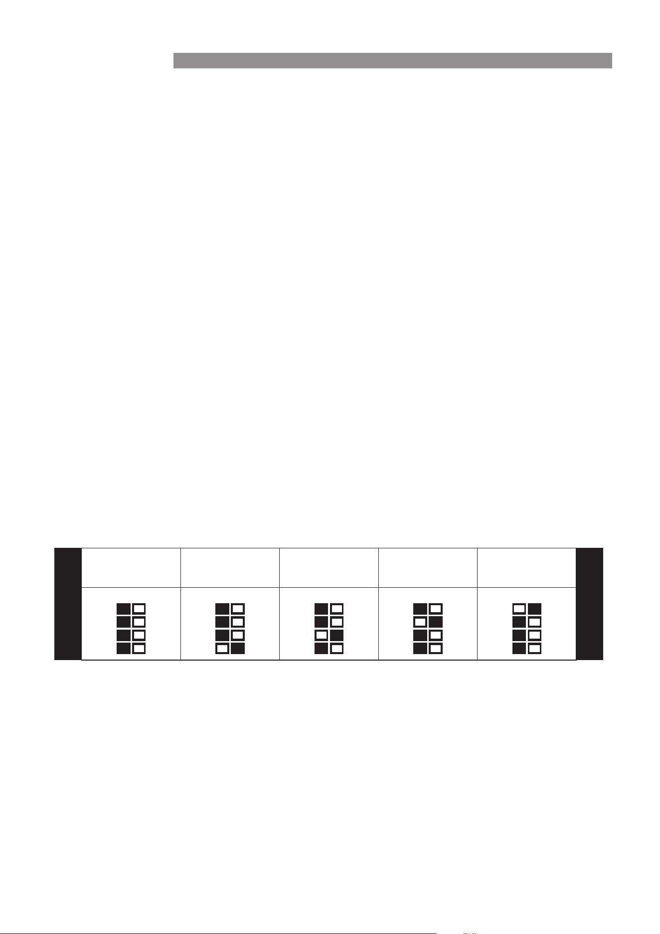
Delivery Temperature Dipswitch Settings
For all Other Models
The water heaters are factory pre-set to various maximum delivery temperatures depending on model and their
intended application. For the majority of applications, the factory pre-set temperature is appropriate. The customer
can follow the Operation Instruction to select the desired temperature by touch screen.
A maximum delivery of 60°C is hot enough for most domestic applications and is suitable for use with thermostatic
mixing valves and tempering valves. Local regulations and or the requirements of AS/NZS 3500.4 MUST be
considered regarding the temperature limitations of hot water supplied to areas used primarily for personal hygiene.
The temperature of the water to these areas may be limited to 50°C or less.
FACTORY DEFAULT
DELIVERY
TEMPERATURE
ON OFF
SW1
1 2 3 4
TEMPERATURE
INCREASE
STEP 1
ON OFF
SW1
1 2 3 4
TEMPERATURE
INCREASE
STEP 2
ON OFF
SW1
1 2 3 4
TEMPERATURE
INCREASE
STEP 3
ON OFF
SW1
1 2 3 4
TEMPERATURE
INCREASE
STEP 4
ON OFF
SW1
1 2 3 4
LOWEST
TEMPERATURE INCREASE
HIGHEST
TEMPERATURE INCREASE
COMMISSIONING

Rinnai 25 ELECTRIC CFWH_OIM - Issue 1
INSTALLATION RECORD
The Installation Record is a reference for the end user, help line sta and service technicians. Ensuring that this
information is available here will be helpful in the event that a service enquiry is required.
Installer Details for Regulatory Compliance and Support
Installation Company Name:
Address:
Telephone / Mobile Phone: /
Email:
Certicate of Compliance / Certication No.:
Authorised Persons - Licence No.:
Installers Name:
Installers Signature:
Installation Date:
System Details Required for Service Bookings and Support
Water Heater - Model Number *:
Water Heater - Serial Number *:
* This information will need to be copied from the data plate, located on the left hand side of appliance.
Installation Address:
Rinnai 26 ELECTRIC CFWH_OIM - Issue 1
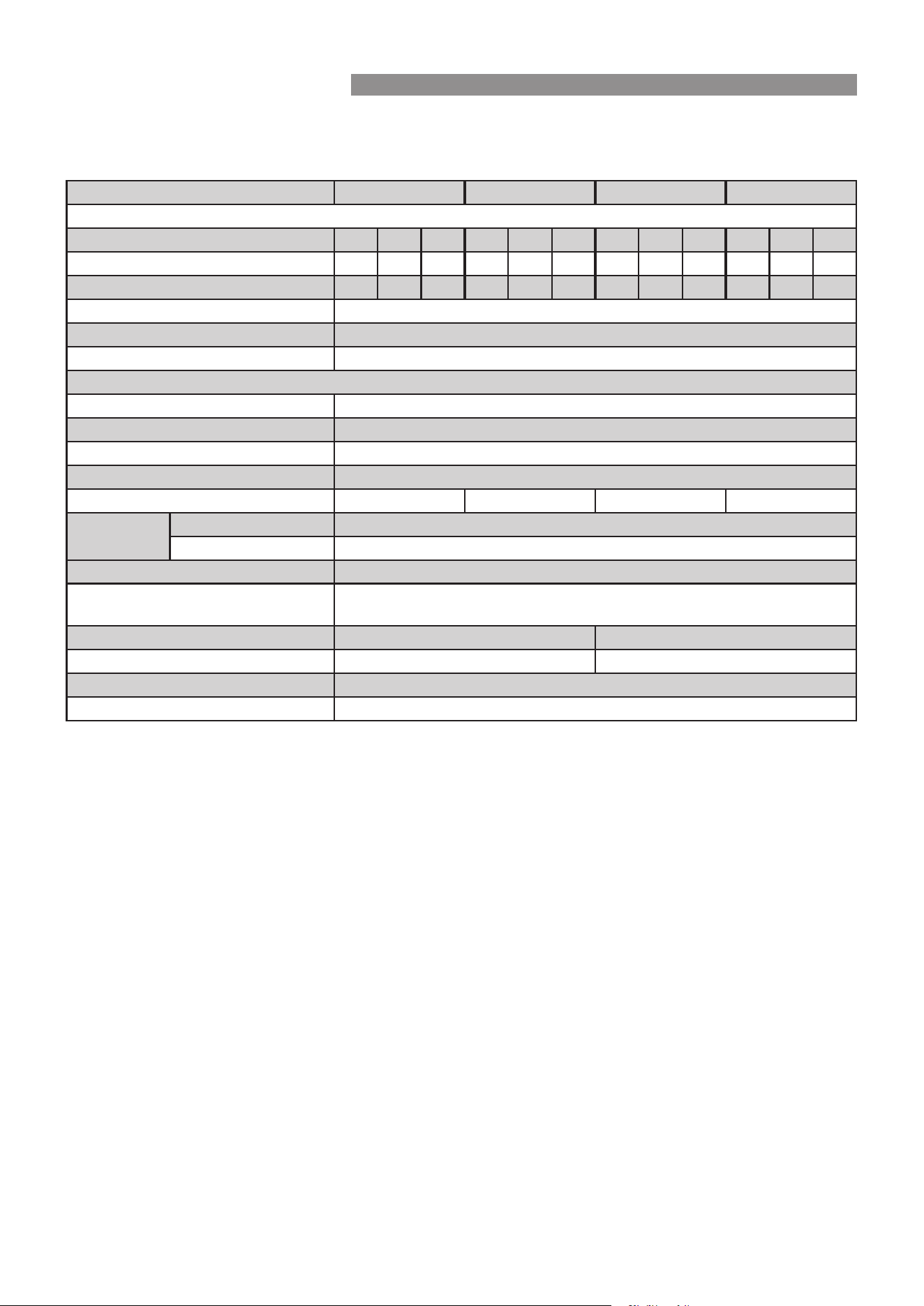
TABLE 1. TECHNICAL SPECIFICATIONS
All dimensions referred to in these instructions are in millimetres, unless otherwise specied.
Model ECF19I50 ECF19I60 ECF29I50 ECF29I60
Electrical data
Rated voltage (VAC) 380 400 415 380 400 415 380 400 415 380 400 415
Rated power rate (kW) 16.2 18 19.4 16.2 18 19.4 24.4 27 28.5 24.4 27 28.5
Rated current (A) 24.5 26 26.9 24.5 26 26.9 37 39.1 39.6 37 39.1 39.6
Phases/Frequency 3 phase 50Hz
Water resistivity (Ω.cm) ≥ 800
Conductivity (μS/cm) ≤ 1250
Plumbing connection / installation
Installation Indoor installation
Dimensions (mm) H x W x D 483 x 228 x 95
Weight (kg) 4.3
Water connection G ½’ Female or R ½’ Male
Temperature range (°C) 30 - 50 30 - 60 30 - 50 30 - 60
Water supply
pressure
Min (kPa) 100
Max (kPa) 850
Minimum operating ow rate (L/min) 2.5
Ambient operating temperature
range (°C)
5 - 45
Flow rate @ 28k (L/min) 9.9 @ 415V 14.5 @ 415V
Flow rate @ 50k (L/min) 5.5 @415V 8.0 @ 415V
IP Rating IP25
Colour Euro White
SPECIFICATIONS

Rinnai 27 ELECTRIC CFWH_OIM - Issue 1
NOTES

28 HW_ELECTRIC CFWH_OIM Issue 1 – March 2024
Rinnai Australia Pty Ltd
ABN 74 005 138 769 | AU45204
100 Atlantic Drive, Keysborough, Victoria 3173
P.O. Box 460, Braeside, Victoria 3195
Tel: (03) 9271 6625
National Help Line
Tel: 1300 555 545*
Monday to Friday, 8.00 am to 5.00 pm EST.
After Hours Hot Water Service Line
Tel: 1800 000 340*
*Cost of a local call may be higher from a mobile phone.
(National calls from public phones in Australia are free.)
For further information visit www.rinnai.com.au
or email [email protected]
Rinnai New Zealand Ltd
105 Pavilion Drive, Mangere, Auckland
PO Box 53177, Auckland Airport, Auckland 2150
Tel: (09) 257-3800
Toll Free: 0800 764-624
For further information visit:
www.rinnai.co.nz
youtube.com/rinnainz
facebook.com/rinnainz
or email info@rinnai.co.nz
Rinnai has a Service and Spare Parts network with
personnel who are fully trained and equipped to give
the best service on your Rinnai appliance. If your
appliance requires service, please call our National
Help Line. Rinnai recommends that this appliance be
serviced every 12 months.
With our policy of continuous improvement, we
reserve the right to change, or discontinue at any time,
specifications or designs without notice.