Loading ...
Loading ...
Loading ...
www.PyleUSA.com www.PyleUSA.com
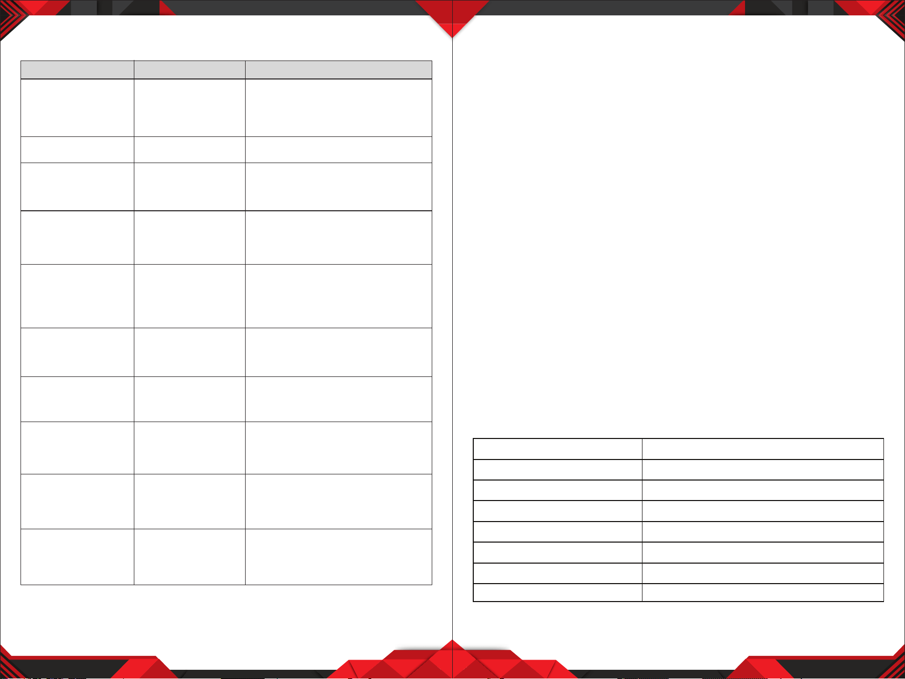
TROUBLESHOOTING
9 10
SYSTEM SPECIFICATIONS
• RF Carrier Frequency Range:
Approximately 523 to 597.8 MHZ (Available frequencies depend on
applicable regulations in country where system is used).
• Operating Range: 50m (approximately 164ft) under typical conditions
• Audio Frequency Response: 100 to 18,000Hz, ±3dB
• THD: <1%
• Mobile state Range: > 100dB
Operating Temperature Range
-20.2°F to 165.2°F (-29°C to 74°C)
NOTE: Battery characteristics may limit this range.
OPTIONAL ACCESSORIES
1/4" to 1/4" Cable (The Guitarist -UHF only)
1/4" to Miniature Connector
1.8 Meter (6ft.) Receiver-Mixer Cable
RECEIVER SPECIFICATION
PROBLEM INDICATOR STATUS SOLUTION
No Sound
No Sound
No Sound
No Sound
No Sound
Sound level diers from
the level of a cabled
Instrument.
Sound level diers from
the level of dierent
guitars
Distortion level increases
gradually
Bursts of noise or other
audible radio signals
present
Momentary loss of
sound as transmitter is
moved around
performing area.
Receiver signal indicators
A/B lights glowing
Receiver signal indicators
A/E lights glowing
Signal indicators A/B
lights ON
Receiver signal
indicator A/B lights OFF
when sound is lost
Red transmitter
indicator is not
ashing
Red receiver POWER
light o
Receiver signal
indicators A/B lights
o. Transmitter and
receiver POWER lights
glowing
Receiver signal
indicators A/B lights
glowing
Red transmitter
indicator is ashing
Slide transmitter POWER ON/OFF switch
to ON position. Make sure battery is
inserted properly, observing battery (+/-).
If the battery is inserted properly, replace
with fresh battery.
Slide transmitter MUTE/ON switch to ON
position
Make sure AC adapter is securely
plugged into electrical outlet and into DC
input connector. Make sure AC electrical
outlet works and supplies proper voltage
Trun up receiver volume control. Conrm
that the output connections from the
receiver to the external equipment are
secure
Conrm transmitter and receiver~
frequency match. Move transmitter
closer to receiver.
Adjust transmitter gain level to
compensate.
Adjust receiver volume as necessary
Readjust transmittergain level to
compensate dierences in guitar outputs
Replace transmitter battery
Identify potential sources of interference
(other RF sources) and turn OFF, remove
or use a wireless system operating on a
dierent frequency
Reposition receiver and perform
walk-through again. If audio dropouts
persist, mark “dead” spot-and avoid them
during performance.
Receiver signal indicators
A/B lights and
transmitter LOW
BATTERY light glowing
Power Requirements
120
V
or
230
V
A
C
adaptor
with
2.
1
mm
femal
e
plug
Power Requirements
Signal/Noise
Ratio
MORE THAN
85dB
Border Upon Channel
Rejection
MORE
THAN
70dB
Image
& Spurious Rejection
MORE
THAN
70dB
Audio Output
Level
()
.±300mV
Receiving Sensitivity
-105dBm
Dimensions
12-15V DC nominal, 1000mA
394MM X 205MM X 52MM
Loading ...