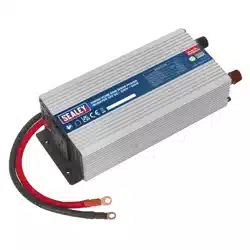
12V DC PURE SINE WAVE POWER INVERTERS
- 230V 50Hz
MODEL NO: PSI300.V3, PSI600.V3, PSI1000.V2
Thank you for purchasing a Sealey product. Manufactured to a high standard, this product will, if used according to these
instructions, and properly maintained, give you years of trouble free performance.
1. SAFETY
▲ DANGER! - Beware, lead-acid batteries generate explosive gases during normal battery operation.
8 DO NOT smoke or allow a spark or flame in the vicinity of the battery or engine.
9 If the battery terminals are corroded or dirty, clean them before attaching the leads.
WARNING! To prevent the risk of sparking, short circuit and possible explosion DO NOT drop metal tools in the battery area, or allow
them to touch the battery terminals.
9 Before attaching to battery, remove personal metallic items such as rings, bracelets, necklaces and watches. A lead acid battery can
produce a short-circuit current which is high enough to weld such items to the vehicle and cause severe burns.
9 Keep children and unauthorised persons away from the working area.
WARNING! DO NOT use on any vehicles other than those with 12Volt DC systems.
WARNING! For delicate items such as laptops, an anti-surge device is recommended.
8 DO NOT connect to any AC power source.
8 DO NOT disassemble. The inverter must be checked by qualified service personnel only.
8 DO NOT get inverter wet or use in damp or wet locations or areas where there is condensation.
8 DO NOT use the inverter for any purpose other than for which it is designed.
8 DO NOT pull the cables or clips from the battery terminals.
8 DO NOT operate the inverter if damaged.
8 DO NOT connect to a positive earthed system. Ensure you have the polarity correct before connecting, red clip to positive (+) battery
terminal and black clip to negative (-) battery terminal.
9 Before connecting ensure nothing is plugged into the inverter, and the inverter is switched OFF.
WARNING! Inverters become hot during use.
9 When not in use store inverter in a safe, dry, childproof location.
WARNING! The warnings, cautions and instructions in this manual cannot cover all possible conditions and situations that
may occur. It must be understood by the operator that common sense and caution are factors which cannot be built into this
product, but must be applied by the operator.
NOTE: This appliance is not intended for use by persons (including children) with reduced physical, sensory or mental capabilities or
lack of experience and knowledge, unless they have been given supervision or instruction concerning the use of the appliance by a
person responsible for their safety. Children should be supervised to ensure that they do not play with the appliance.
2. INTRODUCTION
Pure sine wave inverters have been designed to produce the same AV frequency produced on the grid, making them more reliable
than traditional inverters, without any uctuation in power or performance. Operates from a 12V DC power supply found in cars,
caravans, boats and HGVs. High performance outlet eliminates electrical interference, reducing noise levels during use. Suitable for
powering small TVs, laptops, power tools and various electrical equipment within the wattage rating of the inverter. Includes USB outlet
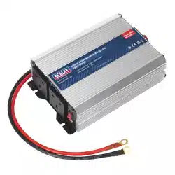
for charging and operating small electric devices. Aluminium case provides durability and maximum heat dissipation. Safety features
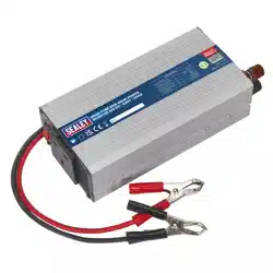
include automatic overload shutdown and short circuit protection. Supplied with a vehicle accessory plug and/or battery clips/terminals
depending on model.
3. SPECIFICATION
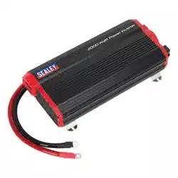
MODEL NO: PSI300 PSI600 PSI1000
Continuous Output: 300W 600W 1000W
Dimension (W x D x H): 205 x 115 x 60mm 260 x 115 x 60mm 315 x 140 x 80mm
Input Voltage: 12V/24V 12V/24V 12/DC
Nett Weight: 0.88kg 1.16kg 2.69kg
Output Frequency: 50Hz 50Hz 50Hz
Output Voltage: 230V 230V 230V AC/USB 5V 500Ma
Supply Connection: Battery Terminal Leads, Car
Socket Plug, Battery Clips
Battery Terminal Leads Battery Terminal Leads
USB Output: 5V/1A 5V/1A N/A
PSI300.V3, PSI600.V3, PSI1000.V2 Issue 3 (3) 22/03/24
Original Language Version
© Jack Sealey Limited
Refer to
instructions
Electrical shock
hazard
Warning!
Battery Charging
Warning!
IMPORTANT: PLEASE READ THESE INSTRUCTIONS CAREFULLY. NOTE THE SAFE OPERATIONAL REQUIREMENTS, WARNINGS & CAUTIONS. USE
THE PRODUCT CORRECTLY AND WITH CARE FOR THE PURPOSE FOR WHICH IT IS INTENDED. FAILURE TO DO SO MAY CAUSE DAMAGE AND/OR
PERSONAL INJURY AND WILL INVALIDATE THE WARRANTY. KEEP THESE INSTRUCTIONS SAFE FOR FUTURE USE.
4. OPERATION
4.1. POWER SOURCE REQUIREMENTS
4.1.1. The inverter must be connected to a 12V DC negative earth system. DO NOT use with a positive earth system.
4.1.2. The power source must be capable of providing between 10.5V and 15.0V and able to supply the necessary current to operate the load.
4.2. CONNECTING BATTERY LEADS TO INVERTER
9 Check the battery is 12VDC. DO NOT use with a 6V or 24V battery.
9 Ensure that the inverter is switched OFF and no flammable fumes are present before connecting to the battery.
4.3. PSI300
4.3.1. Select either vehicle accessory plug lead or battery terminal clips.
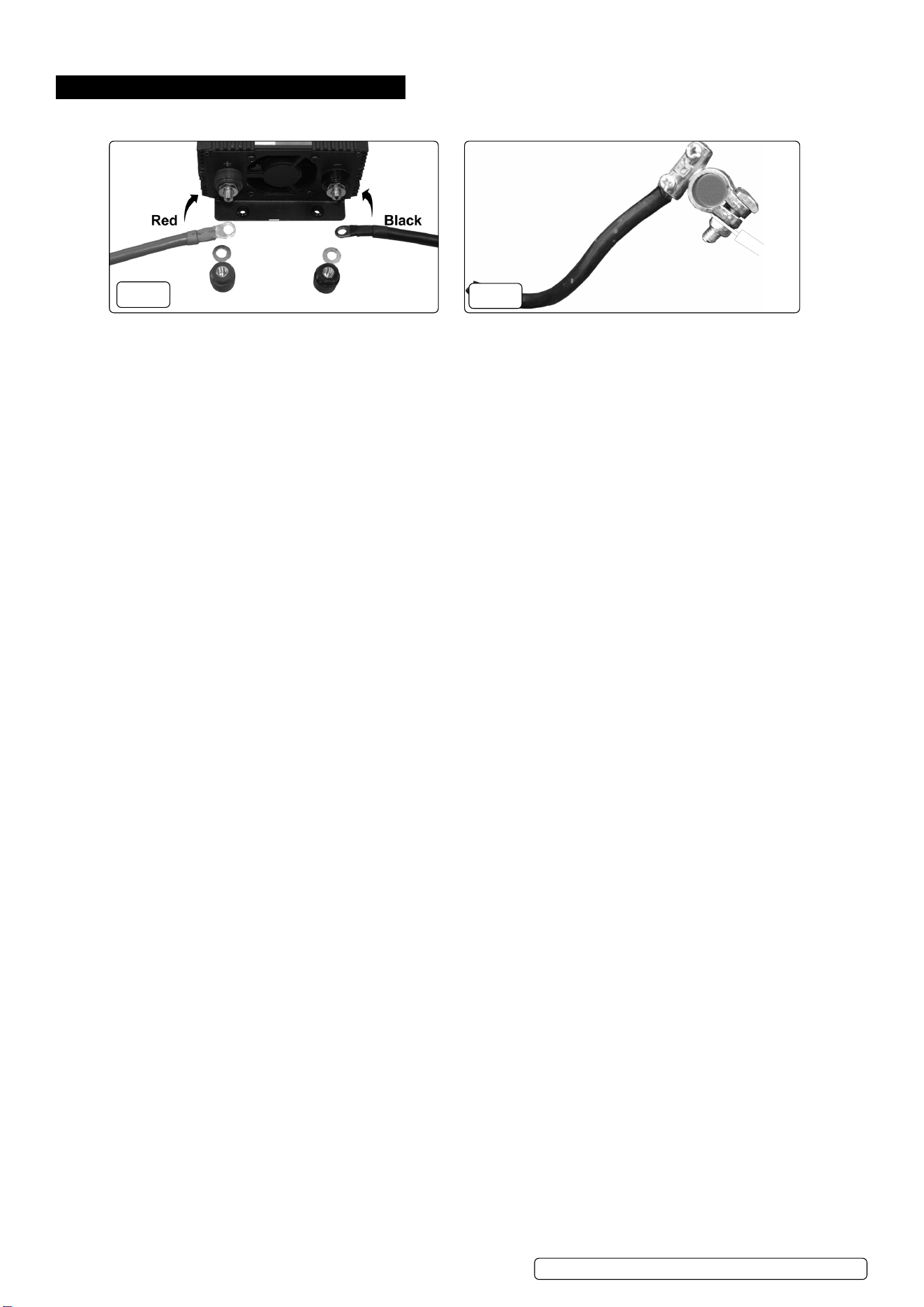
4.3.2. To attach the battery leads remove the terminal caps from the rear of the inverter (fig.1).
4.3.3. Place the black lead eyelet connector over the black (-) terminal post on the inverter, replace and tighten the terminal cap.
4.3.4. Place the red lead eyelet connector over the red (+) terminal post on the inverter, replace and tighten the terminal cap.
4.3.5. If using the vehicle accessory plug lead, plug into the vehicle accessory socket. Some vehicle accessory sockets are not permanently
live; if the inverter does not operate immediately, try turning the ignition key to the first position.
4.3.6. If using battery terminal clips, ensure the battery terminals are clean; if necessary clean away any corrosion.
4.3.7. Connect the red (+) clip then black (-) clip to red (+) and black (-) terminals of the battery.
4.4. PSI600
4.4.1. Attach leads to the inverter as in 4.3.2. and 4.3.3. above.
4.4.2. Ensure the battery terminals are clean; if necessary clean away any corrosion. Connect the red (+) clip then black (-) clip to red (+) and
black (-) terminals of the battery.
4.5. PSI1000
4.5.1. Attach leads to the inverter as in 4.3.2. and 4.3.3. above.
4.5.2. Undo the securing bolt for the red (+) battery terminal and secure the red battery lead to the red (+) terminal post on the battery (fig.2).
4.5.3. Undo the securing bolt for the black (-) battery terminal and secure the black battery lead to the black (-) terminal post on the battery (fig.3).
4.5.4. Check all connections are secure (fig.1 and fig.2).
4.6. CONNECTION TO LOAD
Most electrical appliances, tools etc, have a rating plate indicating the power consumption in Amps or Watts. Use these ratings
to ensure they remain under the inverters continuous capacity. If the rating is shown in amps, multiply the value by the voltage
(230V) to determine the wattage.
4.6.1. Ensure that the inverter is switched OFF. Plug the equipment you wish to use into the inverter’s 3 pin socket or into the USB port as required.
4.6.2. Make sure the load does not exceed the wattage rating of the inverter.
4.6.3. Switch the inverter on, check that everything is working and the green LED is lit (fig.3).
WARNING! DO NOT connect the inverter to any AC distribution wiring or any AC load circuit in which the neutral conductor is connected
to ground (earth) or to the negative of the DC (battery) source.
4.7. PLACEMENT OF INVERTER
4.7.1. For best and safest operation the inverter should be placed on a flat and stable surface.
4.7.2. Use only in a dry location. DO NOT allow the inverter to get wet.
4.7.3. Use in cool ambient temperatures of between 0°C and 40°C. DO NOT place on or near a heating vent.
4.7.4. Allow sufficient space around the inverter for cooling. If the inverter overheats it will shut down and will not restart until it has cooled down.
8 DO NOT use near flammable materials or anywhere that flammable gasses could accumulate.
WARNING! The inverter may become uncomfortably hot during extended periods of full power use.
WARNING! DO NOT place on or near materials that may be affected by heat.
4.8. WATTAGE LOADING
4.8.1. Inductive loads, such as TV’s and stereos, require more current to operate than do resistive loads of the same wattage rating. Induction
motors, as well as some televisions, may require 2 to 6 times their wattage rating to start up. The most demanding in this category are
those that start under load, such as compressors and pumps. Testing is the only denitive way to determine whether a specic load
can be started and how long it can run. The unit will simply shut down if it is overloaded. To restart the unit after a shutdown due to
overloading, remove the overload. NOTE: The inverter will not operate high wattage appliances or equipment that produce heat, such
as hair dryers, microwave ovens and toasters.
4.9. BATTERY OPERATING TIME
4.9.1. The battery operating time will vary depending on battery capacity and the current draw from the inverter. It is recommended that the
operator start the engine every 15 minutes to recharge the battery. This will prevent any unexpected shutdown of the equipment and
will ensure that there is always sucient battery capacity to start the vehicle. The inverter may be used either with the engine running
or turned o. However, the inverter must be switched OFF when starting the vehicle.
PSI300.V3, PSI600.V3, PSI1000.V2 Issue 3 (3) 22/03/24
Original Language Version
© Jack Sealey Limited
Indicative 12 Volt battery terminals
Red (+) post Black (-) post
Inverter connection
Red (+) Black (-)
FIG.2
FIG.1
4.9.2. The inverter draws less than 1.0 Ampere from the battery when it is not supplying power to a load (see section 2 for exact gure).
In most cases, the inverter may be left connected to the battery when it is not in use. If the vehicle will not be used for several days,
disconnect the unit from the battery.
4.10. THE INVERTER MONITORS THE FOLLOWING POTENTIALLY HAZARDOUS CONDITIONS:
4.10.1. Low Battery Voltage
This condition is not harmful to the inverter but could damage the power source. The inverter automatically shuts down when input
voltage drops to 10.5V. When the condition is corrected, the unit may be restarted.
4.10.2. Short Circuit
Reverse polarity or short circuit of the load will usually result in the opening of the short circuit protection and blowing the fuse(s). As
the fuses are internal we recommend contacting your local repair agent or Sealeys technical help line directly on 01284 757505 for
guidance.
4.10.3. High Temperature
When the temperature of the internal heat sink reaches 65°C, the solid state temperature sensor will automatically shut the unit down.
Once it is allowed to cool, the unit may be restarted.
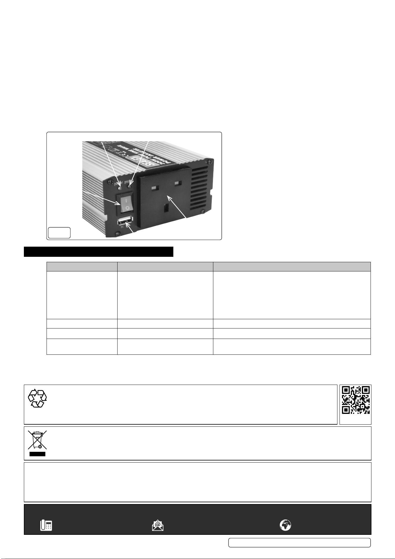
FIG.4
13A Socket
USB Port
On/O switch
Power LED Fault LED
5. TROUBLESHOOTING
PROBLEM POSSIBLE CAUSE SUGGESTED REMEDY
Unit will not operate 1. Poor DC contact
2. Battery voltage below 10.5V.
3. Load draws too much power.
4. Inverter in thermal shutdown.
5. Vehicle battery in poor condition.
6. Fuses blown due to short circuit.
1. Check all DC contacts.
2. Recharge or replace battery
3. Reduce load.
4. Allow inverter to cool.
5. Check / replace battery.
6. Contact repair agent or Sealey technical help line for guidance.
Low output voltage. Check with voltmeter. Use true RMS voltmeter.
Overload LED illuminates. Unit overloaded. Switch off and reduce load.
Television Interference Inverter too close to the television. Locate the inverter as far as possible from the TV, antenna and
other cables.
PSI300.V3, PSI600.V3, PSI1000.V2 Issue 3 (3) 22/03/24
Original Language Version
© Jack Sealey Limited
Sealey Group, Kempson Way, Suffolk Business Park, Bury St Edmunds, Suffolk. IP32 7AR
01284 757500 sales@sealey.co.uk www.sealey.co.uk
WEEE REGULATIONS
Dispose of this product at the end of its working life in compliance with the EU Directive on Waste Electrical and Electronic Equipment
(WEEE). When the product is no longer required, it must be disposed of in an environmentally protective way. Contact your local solid
waste authority for recycling information.
Note: It is our policy to continually improve products and as such we reserve the right to alter data, specications and component parts
without prior notice. Please note that other versions of this product are available. If you require documentation for alternative versions, please
email or call our technical team on technical@sealey.co.uk or 01284 757505.
Important: No Liability is accepted for incorrect use of this product.
Warranty: Guarantee is 12 months from purchase date, proof of which is required for any claim.
ENVIRONMENT PROTECTION
Recycle unwanted materials instead of disposing of them as waste. All tools, accessories and packaging should be
sorted, taken to a recycling centre and disposed of in a manner which is compatible with the environment. When
the product becomes completely unserviceable and requires disposal, drain any uids (if applicable) into approved
containers and dispose of the product and uids according to local regulations.
REGISTER YOUR
PURCHASE HERE