5-Port Gigabit Ethernet Switch
Quick Start Guide
Power-On Check
See the following table and check whether your devices are correctly
connected. After proper connection, you can use your switch without
doing any settings.
Indicator Status
Description
PWR
Solid on
Unlit
Solid on
Unlit
Flashing
The switch is powered on normally.
No power supply connected or power supply is
abnormal.
LINK/ACT
The port is connected.
The port is transmitting data.
The port is disconnected or connection is
abnormal.
Please use the power adapter or power cord attached in the package to
supply power to the switch.
The switch supports auto MDI/MDIX of ports, you can use straight-
through cables or crossover cables to connect the switch and opposite
Ethernet devices.
UD32588B
6
7
8
©2023 Hangzhou Hikvision Digital Technology Co.,Ltd. All rights reserved.
About this Manual
• The Manual includes instructions for using and managing the Product. Pictures, charts,
images and all other information hereinafter are for description and explanation only.
The information contained in the Manual is subject to change, without notice, due to
firmware updates or other reasons. Please find the latest version of this Manual at the
Hikvision website (https://www.hikvision.com/).
• Please use this Manual with the guidance and assistance of professionals trained in
supporting the Product.
Trademarks
• and other Hikvision’s trademarks and logos are the properties of Hikvision in
various jurisdictions.
• Other trademarks and logos mentioned arethe properties of their respective owners.
Disclaimer
• TO THE MAXIMUM EXTENT PERMITTED BYAPPLICABLE LAW, THIS MANUAL AND THE
PRODUCT DESCRIBED,WITH ITS HARDWARE, SOFTWARE AND FIRMWARE, ARE PROVIDED“AS
IS” AND “WITH ALL FAULTS AND ERRORS”. HIKVISION MAKES NO WARRANTIES, EXPRESS OR
IMPLIED, INCLUDING WITHOUT LIMITATION, MERCHANTABILITY, SATISFACTORY QUALITY, OR
FITNESS FOR A PARTICULAR PURPOSE.THE USE OF THE PRODUCT BY YOU IS ATYOUR OWN
RISK. IN NO EVENT WILL HIKVISIONBE LIABLE TO YOU FOR ANY SPECIAL, CONSEQUENTIAL,
INCIDENTAL, OR INDIRECT DAMAGES, INCLUDING,AMONG OTHERS, DAMAGES FOR LOSS OF
BUSINESS PROFITS, BUSINESS INTERRUPTION, OR LOSSOF DATA, CORRUPTION OF SYSTEMS,
OR LOSS OF DOCUMENTATION,WHETHER BASED ON BREACH OF CONTRACT,TORT
(INCLUDING NEGLIGENCE), PRODUCT LIABILITY, OR OTHERWISE, INCONNECTION WITH THE
USE OF THE PRODUCT, EVEN IF HIKVISION HAS BEEN ADVISED OF THE POSSIBILITY OF SUCH
DAMAGES OR LOSS.
• YOU ACKNOWLEDGE THAT THE NATURE OF THE INTERNET PROVIDES FOR INHERENT
SECURITY RISKS, AND HIKVISION SHALL NOT TAKE ANY RESPONSIBILITIES FOR ABNORMAL
OPERATION, PRIVACY LEAKAGE OR OTHER DAMAGES RESULTING FROM CYBER-ATTACK,
HACKER ATTACK, VIRUS INFECTION, OR OTHER INTERNET SECURITY RISKS; HOWEVER,
HIKVISION WILL PROVIDE TIMELY TECHNICAL SUPPORT IF REQUIRED.
• YOU AGREE TO USE THIS PRODUCT IN COMPLIANCE WITH ALL APPLICABLE LAWS, AND YOU
ARE SOLELY RESPONSIBLE FOR ENSURING THAT YOUR USE CONFORMS TO THE APPLICABLE
LAW. ESPECIALLY, YOU ARE RESPONSIBLE, FOR USING THIS PRODUCT IN A MANNER THAT
DOES NOT INFRINGE ON THE RIGHTS OF THIRD PARTIES, INCLUDING WITHOUT LIMITATION,
RIGHTS OF PUBLICITY, INTELLECTUAL PROPERTY RIGHTS, OR DATA PROTECTION AND OTHER
PRIVACY RIGHTS. YOU SHALL NOT USE THIS PRODUCT FOR ANY PROHIBITED END-USES,
INCLUDING THE DEVELOPMENT OR PRODUCTION OF WEAPONS OF MASS DESTRUCTION,
THE DEVELOPMENT OR PRODUCTION OF CHEMICAL OR BIOLOGICAL WEAPONS, ANY
ACTIVITIES IN THE CONTEXT RELATED TO ANY NUCLEAR EXPLOSIVE OR UNSAFE NUCLEAR
FUEL-CYCLE, OR IN SUPPORT OF HUMAN RIGHTS ABUSES.
• IN THE EVENT OFANY CONFLICTS BETWEEN THIS MANUAL AND THE APPLICABLELAW,THE
LATTER PREVAILS.
Regulatory Information
FCC Information
Please take attention that changes or modification not expressly approved by the party
responsible for compliance could void theuser’s authority to operate the equipment.
FCC Compliance
This equipment has been tested and foundto comply with the limits for a Class Adigital
device, pursuant to part 15 of the FCC Rules.These limits are designed to provide
reasonable protection against harmful interference when theequipment is operated in a
commercial environment.This equipment generates, uses, and can radiate radio frequency
energy and, if not installed and used in accordance with the instruction manual, may cause
harmful interference to radio communications. Operation ofthis
equipment in aresidential areais likely tocause harmful interferencein which casethe user
will be required to correct theinterference at his own expense.
FCC Conditions
This device complieswith part 15of the FCC Rules. Operation issubject to thefollowing two
conditions:
1. This device may not causeharmful interference.
2. This devicemust accept anyinterference received, including interference that maycause
undesired operation.
EU Conformity Statement
This product and -if applicable - thesupplied accessoriestoo are marked with"CE"
and comply therefore with the applicable harmonized European standards listed
under the EMC Directive 2014/30/EU, theLVD Directive 2014/35/EU,
the RoHS Directive 2011/65/EU.
2012/19/EU (WEEE directive): Products marked with this symbol cannot be
disposed of as unsorted municipal waste in the European Union. For proper
recycling, return this product to your local supplier upon the purchase of
equivalent new equipment, or dispose ofit at designated collection points.
For more information see: www.recyclethis.info
2006/66/EC (battery directive): This product contains a battery that cannot be
disposed of as unsorted municipal waste in the European Union. See the product
documentation for specific battery information. The battery is marked with this
symbol, which may include lettering toindicate cadmium (Cd), lead (Pb),
or mercury (Hg).For proper recycling,return the batteryto your supplieror to a
designated collection point. For more informationsee: www.recyclethis.info
Industry Canada ICES-003 Compliance
This device meets the CAN ICES-3(A)/NMB-3(A) standards requirements.

2
3
Applicable Models
This manual is applicable to 5-PortGigabit Ethernet Switch.
Symbol Conventions
The symbols that may be foundin this document are defined asfollows.
• During the installation and utilization of the device, please strictly conform to electrical
safety rules in different nations andregions.
• This is a class A product andmay cause radio interference in which case theuser may be
required to take adequate measures.
• Ensure to usethe attached poweradaptor only andnot to changethe adaptor randomly.
Please refer to specification table forspecific requirements of power adaptor.
• If the product does not workproperly, please contact your dealer orthe nearest service
center.
• Never attempt to disassemble the device yourself. (We shall not assumeany
responsibility for problems caused by unauthorizedrepair or maintenance.)
• The device must be installed in machine room only, and only maintenance staff or
qualified person should access to thedevice.
• Do not touch the upper coverarea of the device that maybe overheated.
• Power must be shut down during cable connection, device installation and
dismantlement.
• You shall acknowledge that the use of the device with Internet access might be under
network security risks, please strengthen protection for your personal information and
data security. If you find thedevice might be undernetwork securityrisks, please contact
with us.
• Proper configuration of all passwords and other security settings is the responsibility of
the installer, and you shall keepuser name and passwords properly.
• Please keep all original packing materials properly. If the product does not work
properly, pack the switch in its original packing materials for shipping. We shall not
assume any responsibility for damages caused by improper packing materials during
shipping.
4
5
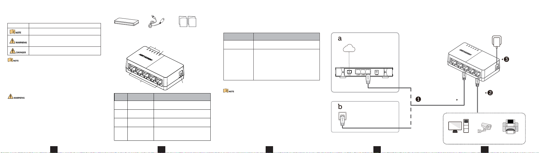
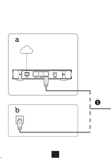
Device Connection
Connect your devices according to your actual networking requirements.
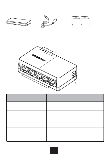
Appearance
Packing List
1
Switch × 1
Power Adapter × 1
•Prepare screws yourself.
•Ensure that the distance between the two screws equals to the distance
between the two hanging holes.
•Set aside at least 4 mm of the screw bodies outside the wall.
Device Installation
Please select the appropriate installation method according to the actual
needs.
Installation Method
Steps
Desktop Installation
Wall-Mounted
Installation
Place the device on the desk.
1. Check the distance between the two hanging
holes on the rear cover of the device.
2. Insert two M4 screws into the wall.
3. Align the hanging holes with the screws, and
hang the device on the screws.
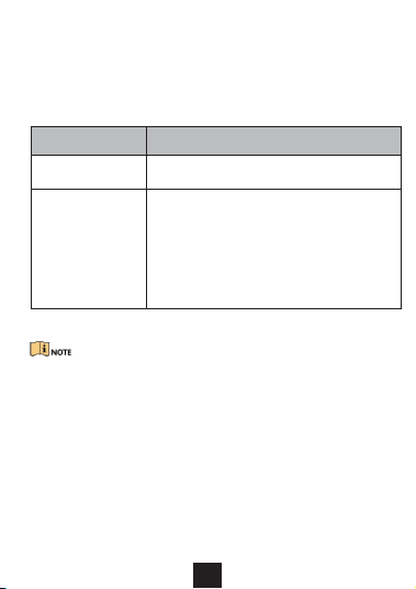
Description
Provides additional information to emphasize or supplement
important points of the main text.
Indicates a potentially hazardous situation, which if not avoided,
could result in equipment damage, data loss, performance
degradation, or unexpected results.
Indicates a hazard with a high level of risk, which if not avoided,
will result in deathor serious injury.
Symbol
Home/Company
Connect to routers
or network ports.
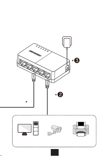
Connect to
terminals.
Connect to
socket.
School dormitory
Network Port
Network Cable
LAN
Network Camera Printer
Network Cable
or
Router
Internet
Computer
•Quick Start Guide × 1
•Multilingual Information
of Network Switch × 1
①
③
④
②
Indicator/Port
No.
Description
①
②
③
Gigabit RJ45 Port
LINK/ACT Indicator
PWR Indicator
Power Supply
Used for connection to another device
via a network cable.
Use the attached power adapter or power
cord to connect the switch to a socket.
Indicates the statuses of Gigabit RJ45
ports 1 to 5.
Indicates the power status of the switch.
④
2
3
Applicable Models
This manual is applicable to 5-PortGigabit Ethernet Switch.
Symbol Conventions
The symbols that may be foundin this document are defined asfollows.
• During the installation and utilization of the device, please strictly conform to electrical
safety rules in different nations andregions.
• This is a class A product andmay cause radio interference in which case theuser may be
required to take adequate measures.
• Ensure to usethe attached poweradaptor only andnot to changethe adaptor randomly.
Please refer to specification table forspecific requirements of power adaptor.
• If the product does not workproperly, please contact your dealer orthe nearest service
center.
• Never attempt to disassemble the device yourself. (We shall not assumeany
responsibility for problems caused by unauthorizedrepair or maintenance.)
• The device must be installed in machine room only, and only maintenance staff or
qualified person should access to thedevice.
• Do not touch the upper coverarea of the device that maybe overheated.
• Power must be shut down during cable connection, device installation and
dismantlement.
• You shall acknowledge that the use of the device with Internet access might be under
network security risks, please strengthen protection for your personal information and
data security. If you find thedevice might be undernetwork securityrisks, please contact
with us.
• Proper configuration of all passwords and other security settings is the responsibility of
the installer, and you shall keepuser name and passwords properly.
• Please keep all original packing materials properly. If the product does not work
properly, pack the switch in its original packing materials for shipping. We shall not
assume any responsibility for damages caused by improper packing materials during
shipping.
4
5
Device Connection
Connect your devices according to your actual networking requirements.
Appearance
Packing List
1
Switch × 1
Power Adapter × 1
•Prepare screws yourself.
•Ensure that the distance between the two screws equals to the distance
between the two hanging holes.
•Set aside at least 4 mm of the screw bodies outside the wall.
Device Installation
Please select the appropriate installation method according to the actual
needs.
Installation Method
Steps
Desktop Installation
Wall-Mounted
Installation
Place the device on the desk.
1. Check the distance between the two hanging
holes on the rear cover of the device.
2. Insert two M4 screws into the wall.
3. Align the hanging holes with the screws, and
hang the device on the screws.
Description
Provides additional information to emphasize or supplement
important points of the main text.
Indicates a potentially hazardous situation, which if not avoided,
could result in equipment damage, data loss, performance
degradation, or unexpected results.
Indicates a hazard with a high level of risk, which if not avoided,
will result in deathor serious injury.
Symbol
Home/Company
Connect to routers
or network ports.
Connect to
terminals.
Connect to
socket.
School dormitory
Network Port
Network Cable
LAN
Network Camera Printer
Network Cable
or
Router
Internet
Computer
•Quick Start Guide × 1
•Multilingual Information
of Network Switch × 1
①
③
④
②
Indicator/Port
No.
Description
①
②
③
Gigabit RJ45 Port
LINK/ACT Indicator
PWR Indicator
Power Supply
Used for connection to another device
via a network cable.
Use the attached power adapter or power
cord to connect the switch to a socket.
Indicates the statuses of Gigabit RJ45
ports 1 to 5.
Indicates the power status of the switch.
④
5-Port Gigabit Ethernet Switch
Quick Start Guide
Power-On Check
See the following table and check whether your devices are correctly
connected. After proper connection, you can use your switch without
doing any settings.
Indicator Status
Description
PWR
Solid on
Unlit
Solid on
Unlit
Flashing
The switch is powered on normally.
No power supply connected or power supply is
abnormal.
LINK/ACT
The port is connected.
The port is transmitting data.
The port is disconnected or connection is
abnormal.
Please use the power adapter or power cord attached in the package to
supply power to the switch.
The switch supports auto MDI/MDIX of ports, you can use straight-
through cables or crossover cables to connect the switch and opposite
Ethernet devices.
UD32588B
6
7
8
©2023 Hangzhou Hikvision Digital Technology Co.,Ltd. All rights reserved.
About this Manual
• The Manual includes instructions for using and managing the Product. Pictures, charts,
images and all other information hereinafter are for description and explanation only.
The information contained in the Manual is subject to change, without notice, due to
firmware updates or other reasons. Please find the latest version of this Manual at the
Hikvision website (https://www.hikvision.com/).
• Please use this Manual with the guidance and assistance of professionals trained in
supporting the Product.
Trademarks
• and other Hikvision’s trademarks and logos are the properties of Hikvision in
various jurisdictions.
• Other trademarks and logos mentioned arethe properties of their respective owners.
Disclaimer
• TO THE MAXIMUM EXTENT PERMITTED BYAPPLICABLE LAW, THIS MANUAL AND THE
PRODUCT DESCRIBED,WITH ITS HARDWARE, SOFTWARE AND FIRMWARE, ARE PROVIDED“AS
IS” AND “WITH ALL FAULTS AND ERRORS”. HIKVISION MAKES NO WARRANTIES, EXPRESS OR
IMPLIED, INCLUDING WITHOUT LIMITATION, MERCHANTABILITY, SATISFACTORY QUALITY, OR
FITNESS FOR A PARTICULAR PURPOSE.THE USE OF THE PRODUCT BY YOU IS ATYOUR OWN
RISK. IN NO EVENT WILL HIKVISIONBE LIABLE TO YOU FOR ANY SPECIAL, CONSEQUENTIAL,
INCIDENTAL, OR INDIRECT DAMAGES, INCLUDING,AMONG OTHERS, DAMAGES FOR LOSS OF
BUSINESS PROFITS, BUSINESS INTERRUPTION, OR LOSSOF DATA, CORRUPTION OF SYSTEMS,
OR LOSS OF DOCUMENTATION,WHETHER BASED ON BREACH OF CONTRACT,TORT
(INCLUDING NEGLIGENCE), PRODUCT LIABILITY, OR OTHERWISE, INCONNECTION WITH THE
USE OF THE PRODUCT, EVEN IF HIKVISION HAS BEEN ADVISED OF THE POSSIBILITY OF SUCH
DAMAGES OR LOSS.
• YOU ACKNOWLEDGE THAT THE NATURE OF THE INTERNET PROVIDES FOR INHERENT
SECURITY RISKS, AND HIKVISION SHALL NOT TAKE ANY RESPONSIBILITIES FOR ABNORMAL
OPERATION, PRIVACY LEAKAGE OR OTHER DAMAGES RESULTING FROM CYBER-ATTACK,
HACKER ATTACK, VIRUS INFECTION, OR OTHER INTERNET SECURITY RISKS; HOWEVER,
HIKVISION WILL PROVIDE TIMELY TECHNICAL SUPPORT IF REQUIRED.
• YOU AGREE TO USE THIS PRODUCT IN COMPLIANCE WITH ALL APPLICABLE LAWS, AND YOU
ARE SOLELY RESPONSIBLE FOR ENSURING THAT YOUR USE CONFORMS TO THE APPLICABLE
LAW. ESPECIALLY, YOU ARE RESPONSIBLE, FOR USING THIS PRODUCT IN A MANNER THAT
DOES NOT INFRINGE ON THE RIGHTS OF THIRD PARTIES, INCLUDING WITHOUT LIMITATION,
RIGHTS OF PUBLICITY, INTELLECTUAL PROPERTY RIGHTS, OR DATA PROTECTION AND OTHER
PRIVACY RIGHTS. YOU SHALL NOT USE THIS PRODUCT FOR ANY PROHIBITED END-USES,
INCLUDING THE DEVELOPMENT OR PRODUCTION OF WEAPONS OF MASS DESTRUCTION,
THE DEVELOPMENT OR PRODUCTION OF CHEMICAL OR BIOLOGICAL WEAPONS, ANY
ACTIVITIES IN THE CONTEXT RELATED TO ANY NUCLEAR EXPLOSIVE OR UNSAFE NUCLEAR
FUEL-CYCLE, OR IN SUPPORT OF HUMAN RIGHTS ABUSES.
• IN THE EVENT OFANY CONFLICTS BETWEEN THIS MANUAL AND THE APPLICABLELAW,THE
LATTER PREVAILS.
Regulatory Information
FCC Information
Please take attention that changes or modification not expressly approved by the party
responsible for compliance could void theuser’s authority to operate the equipment.
FCC Compliance
This equipment has been tested and foundto comply with the limits for a Class Adigital
device, pursuant to part 15 of the FCC Rules.These limits are designed to provide
reasonable protection against harmful interference when theequipment is operated in a
commercial environment.This equipment generates, uses, and can radiate radio frequency
energy and, if not installed and used in accordance with the instruction manual, may cause
harmful interference to radio communications. Operation ofthis
equipment in aresidential areais likely tocause harmful interferencein which casethe user
will be required to correct theinterference at his own expense.
FCC Conditions
This device complieswith part 15of the FCC Rules. Operation issubject to thefollowing two
conditions:
1. This device may not causeharmful interference.
2. This devicemust accept anyinterference received, including interference that maycause
undesired operation.
EU Conformity Statement
This product and -if applicable - thesupplied accessoriestoo are marked with"CE"
and comply therefore with the applicable harmonized European standards listed
under the EMC Directive 2014/30/EU, theLVD Directive 2014/35/EU,
the RoHS Directive 2011/65/EU.
2012/19/EU (WEEE directive): Products marked with this symbol cannot be
disposed of as unsorted municipal waste in the European Union. For proper
recycling, return this product to your local supplier upon the purchase of
equivalent new equipment, or dispose ofit at designated collection points.
For more information see: www.recyclethis.info
2006/66/EC (battery directive): This product contains a battery that cannot be
disposed of as unsorted municipal waste in the European Union. See the product
documentation for specific battery information. The battery is marked with this
symbol, which may include lettering toindicate cadmium (Cd), lead (Pb),
or mercury (Hg).For proper recycling,return the batteryto your supplieror to a
designated collection point. For more informationsee: www.recyclethis.info
Industry Canada ICES-003 Compliance
This device meets the CAN ICES-3(A)/NMB-3(A) standards requirements.