
200A MMA INVERTER WELDER & BATTERY
CHARGER/STARTER
MODEL NO: MW160BC
Thank you for purchasing a Sealey product. Manufactured to a high standard, this product will, if used according to these instructions,
and properly maintained, give you years of trouble free performance.
IMPORTANT: PLEASE READ THESE INSTRUCTIONS CAREFULLY. NOTE THE SAFE OPERATIONAL REQUIREMENTS, WARNINGS &
CAUTIONS. USE THE PRODUCT CORRECTLY AND WITH CARE FOR THE PURPOSE FOR WHICH IT IS INTENDED. FAILURE TO DO
SO MAY CAUSE DAMAGE AND/OR PERSONAL INJURY AND WILL INVALIDATE THE WARRANTY. KEEP THESE INSTRUCTIONS SAFE
FOR FUTURE USE.
1. SAFETY
1.1. ELECTRICAL SAFETY
WARNING! It is the user’s responsibility to check the following:
9 Check all electrical equipment and appliances to ensure that they are safe before using. Inspect power supply leads, plugs
and all electrical connections for wear and damage. Sealey recommend that an RCD (Residual Current Device) is used with
all electrical products.
Electrical safety information. It is important that the following information is read and understood:
9 Ensure that the insulation on all cables and on the appliance is safe before connecting it to the power supply.
9 Regularly inspect power supply cables and plugs for wear or damage and check all connections to ensure that they are secure.
Important: Ensure that the voltage rating on the appliance suits the power supply to be used and that the plug is tted with the correct fuse.
8 DO NOT pull or carry the appliance by the power cable.
8 DO NOT pull the plug from the socket by the cable.
8 DO NOT use worn or damaged cables, plugs or connectors. Ensure that any faulty item is repaired or is replaced immediately
by a qualied electrician.
If the cable or plug is damaged during use, switch o the electricity supply and remove from use.
Ensure that repairs are carried out by a qualied electrician.
9 Always turn o the power supply and disconnect the welder before performing maintenance or repairs.
9 Use a properly grounded power source to prevent electrical shocks.
8 DO NOT overload the welder beyond its rated capacity. Overloading can cause overheating and damage to the machine.
9 If the supply cord is damaged, it must be replaced by the manufacturer, its service agent or similarly qualied persons in order to avoid
a hazard.
9 The battery charger must only be plugged into an earthed socket-outlet
1.2. PERSONAL SAFETY & PERSONAL PROTECTIVE EQUIPMENT (PPE)
9 Always wear a welding helmet with an appropriate shade level to protect your eyes from harmful arc rays.
9 Wear welding gloves made of ame-retardant material to protect your hands from heat, sparks, and molten metal.
9 Wear long-sleeved shirts and trousers made of ame-resistant material to protect your skin from burns.
9 Operators must receive adequate training before using the inverter.
8 DO NOT operate the inverter while under the influence of drugs, alcohol or intoxicating medication, or if tired.
9 Stand correctly keeping a good footing and balance, ensure that the floor is not slippery and wear non-slip shoes.
9 Keep unauthorised persons away from the work area. Any persons working within the area must wear the same protective items.
9 Avoid oily greasy clothing. A spark may ignite them.
8 DO NOT touch the work piece close to the weld as it will be very hot. Allow to cool.
8 DO NOT touch the electrode holder immediately after use. Allow the electrode holder to cool.
1.3. VENTILATION
9 Welding fumes and gases can be hazardous to your health. Ensure adequate ventilation in the work area to prevent the build-up of
fumes and gases.
9 If working in an enclosed space, use a fume extractor to remove welding fumes and gases.
8 DO NOT weld the following metals: galvanized, seed crystal, stainless steel, copper, zinc, readings, beryllium calcium.
8 DO NOT inhale welding mist and gas.
8 DO NOT weld near degreasing or spraying operations, avoid toxic gas phosgene or other simulated gases.
WARNING! If you feel that your eyes and nose are abnormal, stop welding immediately and improve the aerator.
8 DO NOT weld where solvent vapours can be drawn into the welding or cutting atmosphere or where the radiant energy can penetrate to
atmospheres containing even minute amounts of trichloroethylene or perchloroethylene.
9 Prevent dangerous conditions arising by providing adequate ventilation. NEVER ventilate with oxygen.
▲ DANGER! Lead-, cadmium-, zinc-, mercury- and beryllium-, bearing materials, when welded (or cut) may produce harmful concentrations
of toxic fumes. Adequate local exhaust ventilation must be used, or each person in the area as well as the operator must wear an air-
supplied respirator. For beryllium, both must be used. Metals coated with or containing materials that emit toxic fumes should not be
heated unless coating is removed from the work surface, the area is well ventilated, or the operator wears an air-supplied respirator.
8 DO NOT work in an unventilated conned space. If necessary, wear an air-supplied respirator.
Refer to
instructions
Wear a welding
mask
MW160BC Issue 2 (2,3) 13/11/23Original Language Version
© Jack Sealey Limited
Wear protective
gloves
WARNING!
Arc rays
WARNING!
Electricity
WARNING!
Magnetic eld
WARNING!
Fire hazard
Fumes / gases
Use in ventilated
area

1.4. EQUIPMENT INSPECTION
9 Before each use, inspect the welder, cables, electrode holder, and work clamp for any signs of damage, such as frayed wires, cracks,
or loose connections.
8 DO NOT operate the welder if any damage is found. Replace damaged components before proceeding. Use an authorised service
centre to carry out any repairs.
1.5. WORK AREA PRECAUTIONS
9 Keep the work area free of ammable materials to prevent re hazards.
9 Ground the workpiece securely to prevent electrical shocks.
9 Avoid welding in wet or damp environments to minimize the risk of electrical hazards.
9 Fire-proof partitions and door curtains should be used to protect other workers from electric rays and sparks.
9 Fire-ghting equipment should be provided near the welding work area.
9 Locate the inverter in a suitable work area.
9 Keep the work area clean and tidy and free from unrelated materials. Also ensure that the work area has adequate lighting.
8 DO NOT get inverter wet or use in damp or wet locations or areas where there is condensation.
9 First aid facilities and a qualified first aid person should be available during welding operations.
9 For production welding, a separate room or enclosed bay should be provided. In open areas, surround the operation with low reflective,
non-combustible screens or panels. Allow for free air circulation, particularly at floor level. Provide face shields for all persons who will be
looking directly at the weld. Before starting to weld, make sure that screen or bay doors are closed.
9 Always ensure that there is full free air circulating around the outer casing of the machine, and that the louvres are unobstructed.
1.6. ARC RAY AND SPARK PROTECTION
9 Protect yourself and others from arc rays and sparks by using protective screens or barriers.
9 Warn others not to look directly at the welding arc.
9 Use a chipping hammer and wire brush to remove slag and spatter from the weld area to prevent burns and injuries.
1.7. GENERAL SAFETY FOR WELDING
9 Make sure that all workpieces have been cleaned up before welding.
9 Ensure that the workpiece and the electrical connections are good.
9 Keep dry including clothes, work area, wires, welding torch, welding torch and power supply.
9 Wear dry and sealed gloves before welding.
9 Turn o the power before taking o the gloves.
8 DO NOT use the welder in damp conditions.
WARNING! DO NOT use a welding power source for pipe thawing.
8 DO NOT weld containers or pipes which have held flammable materials - gases, liquids or solids.
▲ DANGER! Avoid welding on materials cleaned with chlorinated solvents or near such solvents. Vapours from chlorinated solvents (such as
de-greasers) can be decomposed by the heat of the arc to form PHOSGENE, a highly toxic gas, and other lung and eye irritating products.
The ultraviolet (radiant) energy of the arc can also decompose trichloroethylene and perchloroethylene vapours to form phosgene.
1.8. ELECTROMAGNETIC FIELD
9 Electromagnetic elds can interfere with normal operation of pacemakers. Workers with pacemakers must consult a doctor before use.
1.9. FIRE HAZARD
WARNING! Be aware that ying sparks or falling slag can pass through cracks, along pipes, through windows or doors, and through
wall or oor openings, out of sight of the operator. Sparks and slag can y 10m.
8 DO NOT weld within 10 metres of combustible materials (including building construction materials).
8 DO NOT weld adjacent to openings (concealed or visible) in floors or walls within 10m that can expose combustibles to sparks.
8 DO NOT weld near to walls, ceilings, roofs or metal partitions where there are combustibles that can be ignited by radiant or conducted heat.
9 Have suitable re extinguishing equipment available and someone to use it during welding operations and for some time after welding
ceases. After work is done, check that area is free of sparks, glowing embers, and ames.
1.10. CHARGING FUNCTION
9 Before charging check the electrolyte level and if possible rell it with distilled water to the level specied in the battery documentation.
9 When raising electrolyte levels, follow the instructions in the battery documentation closely.
9 When charging, the battery must be located in a well ventilated area.
9 Keep the battery at room temperature.
9 This equipment is specially designed for indoor use.
8 DO NOT expose the product to rain or humid conditions.
9 The battery charger must only be plugged into an earthed socket-outlet.
9 The battery terminal not connected to the chassis has to be connected rst. The other connection is to be made to the chassis, remote
from the battery and fuel line. The battery charger is then to be connected to the supply mains.
9 After Charging, disconnect the battery charger from the supply mains. Then remove the chassis connection and then the battery connection.
WARNING! DO NOT recharge non-rechargeable batteries.
9 If you want to charge the battery in the car, rst connect the charger clip to the battery terminal correctly (the red clip is clamped at the
positive ‘+’ of the battery); The black clip is clamped on the battery negative pole ‘-’), then select the correct charging voltage (12V or
24V), nally insert the charger plug into the power socket and press the ‘accept’ button to start charging.
9 After charging, rst disconnect the device plug from the power socket, and then remove the clip clamped on the battery.
9 Before starting charging, please read and follow the charging instructions provided by the battery manufacturer. Correctly select
charging current and voltage.
9 Always place the battery and equipment on a at and hard surface without tilting the battery.
9 Before connecting the power cord, make sure that the power parameters match the rated parameters of the equipment.
8 DO NOT over-tighten the cable.
8 DO NOT place the charger on or directly above the battery. It may corrode components in the equipment and cause damage to the battery.
8 DO NOT use re near the battery.
9 If the device is connected to a power supply, do not touch the output.
9 Before each use, check the condition of the equipment, including the status of power cord and charging cable. If you nd any defects,
please do not use. Damaged cables and wires must be replaced with new cables and wires in professional facilities.
9 Keep the equipment away from bystanders, especially children.
9 Before use, ensure that the battery terminals are clean and free of corrosion.
9 Ensure the best possible electrical contact between the battery terminal and the device charging clip.
MW160BC Issue 2 (2,3) 13/11/23Original Language Version
© Jack Sealey Limited
8 DO NOT charge a frozen battery. Before starting, move the battery to a position to completely thaw the electrolyte.
8 DO NOT heat the battery to accelerate thawing.
9 Liquid leakage from the battery is not allowed. Leakage of electrolyte can lead to short circuit, which endangers health and life.
9 Children from age 8 years and above, persons with reduced physical, sensory, or mental capabilities those with lack of experience and
knowledge can use the appliance, if they have been given supervision or instruction concerning use of the appliance in a safe way to
understand the hazards involved.
8 DO NOT let children play with the appliance.
9 Cleaning and user maintenance on the appliance shall not be made by children without supervision.
9 The appliance shall be disconnected from its power source during service and when replacing parts and, if that the removal of the plug
is foreseen, it shall be clearly indicated that the removal of the plug has to be such that an operator can check from any of the points to
which he has access that the plug remains removed.
1.11. CABLE CONNECTIONS
9 Keep the inverter and cables in good working order and condition. Take immediate action to repair or replace damaged parts.
9 Ensure that there is no obstruction to the flow of clean, cool air and ensure that there are no conductive dusts, corrosive vapours or
humidity which could enter the inverter and cause serious damage.
1.12. PRODUCT CARE & MAINTENANCE
8 DO NOT attempt to fit any unapproved electrode holder, components, or parts to the inverter unit.
9 Keep the inverter clean for best and safest performance.
WARNING! If the case is opened for maintenance or repair, wait 10-15 seconds after the unit is switched o for the capacitor to discharge.
2. INTRODUCTION
3-in-1 IGBT Inverter that allows the user to MMA weld, charge batteries and jump start vehicles with flat batteries. Three functions include
a 160A MMA welder, 30A battery charger and a 200A start function. Unit can MMA weld a variety of rods including rutile, basic and
stainless from Ø1.6mm up to Ø4mm. Features LED display, with thermal cut-out protection, anti-stick, arc force and hot start functions.
Ultra-compact and lightweight unit weighing just 5kg approx. Suitable for charging VRLA (Lead Acid), GEL, AGM/EFB and Leisure
Batteries on 12 and 24V systems. Supplied with 1.6m 16mm² cable with electrode holder and a 1.4m 16mm² earth clamp and cable, 1m
200A charging clamps and 1.8m Power cable.
3. SPECIFICATION
Model No: ......................................................MW160BC
Plug Type: ....................................................... Bare Wire
MMA Ouput: .......................................................20-160A
Duty Cycle:....25% @ 160A, 60% @ 124A, 100% @ 80A
Start Peak: ..............................................................200A
Charge Peak: ............................................................ 30A
Cable & Clamp length: ............................................... 1m
Max Size Battery (Ah) Full Charge in 12hrs ..........400Ah
Supply: ....................................................... 230V ~ 50Hz
Battery Type: ................................................ VRLA (SLA)
..................... GEL, AGM/EFB, Leisure (Deep Discharge)
IP Rating: .................................................................IP21
EMC Classication: .......................................................F
System: ................................................................ 12/24V
Insulation Class: ........................................................... H
4. OPERATION
IMPORTANT: Ensure you have read and understood the safety instructions and familiarised yourself with the gures below before
operating the device.
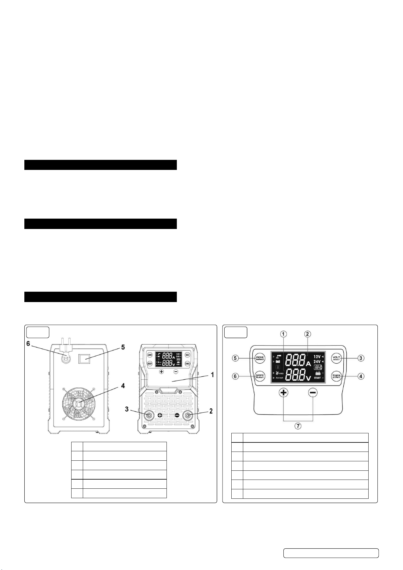
FIG.2
1 Voltage value display
2 Current value display
3 12V/24V battery selection button
4 Charge/start selection button
5 Welder/battery charger function selection button
6 Function conrmation and VRD switch button
7 Parameter adjustment button
1 Operation panel
2 Negative interface
3 Positive interface
4 Fan
5 Power switch
6 Power cable - reference only
FIG.1
MW160BC Issue 2 (2,3) 13/11/23Original Language Version
© Jack Sealey Limited
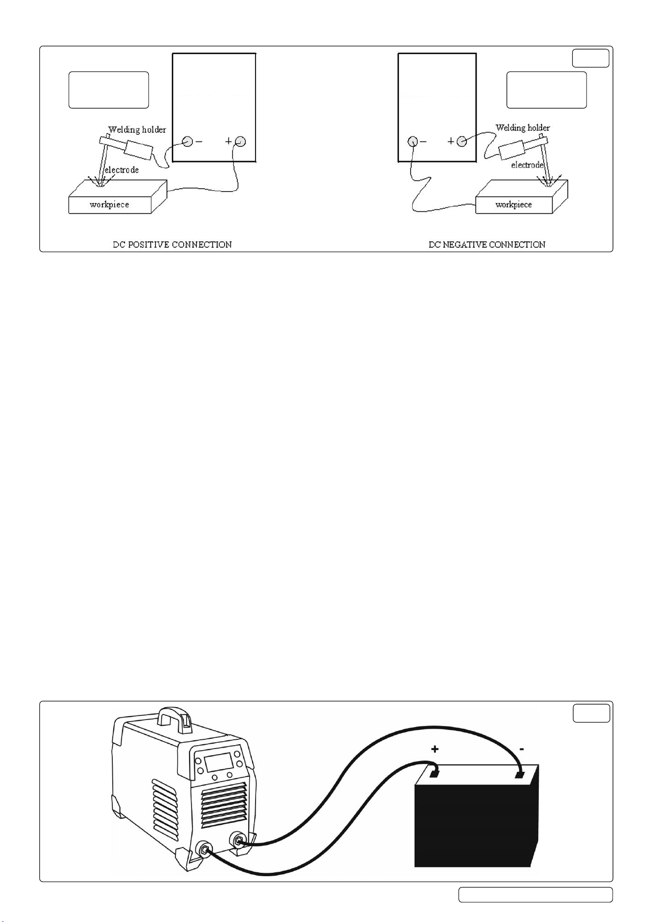
FIG.3
ALKALINE
ELECTRODE
CONNECTION
ACID
ELECTRODE
CONNECTION
4.1. MMA WELDING
4.1.1. Connect the electrode holder and earth clamp correctly (g.3).
4.1.2. Plug in the power supply and turn on the switch.
4.1.3. Select to MMA function.
4.1.4. Turn ON/OFF the VRD function accordingly.
NOTE: Turning on the VRD function can prevent accidental electric shock caused by touching the positive and negative output
terminals simultaneously. It is recommended to turn on this function.
4.1.5. Set the current according to the thickness and electrode diameter.
4.1.6. Start welding.
4.2. MMA WELDING - ALKALINE & ACID ELECTRODES (FIG.3)
MMA (Manual Metal Arc) welding, also known as stick welding, can be performed using both alkaline and acid electrodes. The choice
between them depends on the specic welding application and the type of material you are working with.
4.2.1. Alkaline Electrode Connection
Alkaline electrodes are typically used with basic or alkaline-coated welding rods. These rods have a basic or high-cellulose coating,
which stabilizes the welding arc and produces a smoother weld bead. Alkaline electrodes are often preferred for welding thicker metals
and in situations where a strong, stable welding arc is required. They are suitable for applications where the appearance and quality
of the weld are important. Alkaline electrodes are usually connected to the positive terminal (DC+ or reverse polarity) for better arc
stability.
4.2.2. Acid Electrode Connection
Acid electrodes are used with rutile-coated or acid-coated welding rods. These electrodes oer good penetration and are versatile
for various welding tasks. Applications: Acid electrodes are suitable for general-purpose welding and can be used on a wide range of
materials. They are often chosen for their ease of use and versatility. Acid electrodes are typically connected to the negative terminal
(DC- or straight polarity) for optimal performance.
The choice between alkaline and acid electrodes and their corresponding electrode connections should be made based on the
specic welding requirements and the materials being joined. It’s essential to follow the manufacturer’s recommendations for electrode
selection and polarity to achieve the best welding results. Additionally, proper welding techniques and safety precautions are critical for
a successful welding operation.
4.3. BATTERY CHARGING
4.3.1. Plug in the power supply and turn on the switch.
4.3.2. Select the charger function, then select the charging function (g.2).
4.3.3. According to the nominal voltage, select the correct output voltage (12V or 24V).
4.3.4. Connect the red charging clip to the red output port (positive), and the black charging clip to the black output terminal (negative).
Connect the red charging clip to the positive pole (+) and the black charging clip to the negative pole (-).
4.3.5. Press the “accept” button to start charging
NOTE: The battery terminal not connected to the chassis has to be connected rst. The other connection is to be made to the chassis,
remote from the battery and fuel line. The battery charger is then to be connected to the supply mains.
4.3.6. After Charging, disconnect the battery charger from the supply mains. Then remove the chassis connection and then the battery
connection.
FIG.4
MW160BC Issue 2 (2,3) 13/11/23Original Language Version
© Jack Sealey Limited

Sealey Group, Kempson Way, Suffolk Business Park, Bury St Edmunds, Suffolk. IP32 7AR
01284 757500 sales@sealey.co.uk www.sealey.co.uk
Note: It is our policy to continually improve products and as such we reserve the right to alter data, specications and component parts without prior notice.
Important: No Liability is accepted for incorrect use of this product.
Warranty: Guarantee is 12 months from purchase date, proof of which is required for any claim.
ENVIRONMENT PROTECTION
Recycle unwanted materials instead of disposing of them as waste. All tools, accessories and packaging should be
sorted, taken to a recycling centre and disposed of in a manner which is compatible with the environment. When
the product becomes completely unserviceable and requires disposal, drain any uids (if applicable) into approved
containers and dispose of the product and uids according to local regulations.
REGISTER YOUR
PURCHASE HERE
4.4. START CAR
4.4.1. Plug in and turn on the power switch (g.1).
4.4.2. Select the charger function, and then select the start function.
4.4.3. According to the battery’s nominal voltage, choose the correct output voltage (12V or 24V).
4.4.4. Connect the red charging clip to the red output terminal (positive) of the machine, and the black charging clip to the black output
terminal (negative) of the machine.
4.4.5. Connect the red charging clip to the positive pole (+) of the battery and the black charging clip to the negative pole (-) of the battery.
4.4.6. Preset starting current.
4.4.7. Press the “accept” button to start the car (g.2).
5. MAINTENANCE
WARNING! Incorrect equipment maintenance can cause personal injury or death.
9 Always use an authorised service centre for repairs/maintenance.
9 Turn o the power supply and unplug the device before carrying out any maintenance.
9 Ensure that cables, ground wires, connectors, main leads, and power cords are working properly.
9 Keep the equipment safe and intact.
8 DO NOT abuse the device. Only use the device for tasks it is designed for.
8 DO NOT replace any spare parts - use an authorised serviced centre.
MW160BC Issue 2 (2,3) 13/11/23Original Language Version
© Jack Sealey Limited