1

2
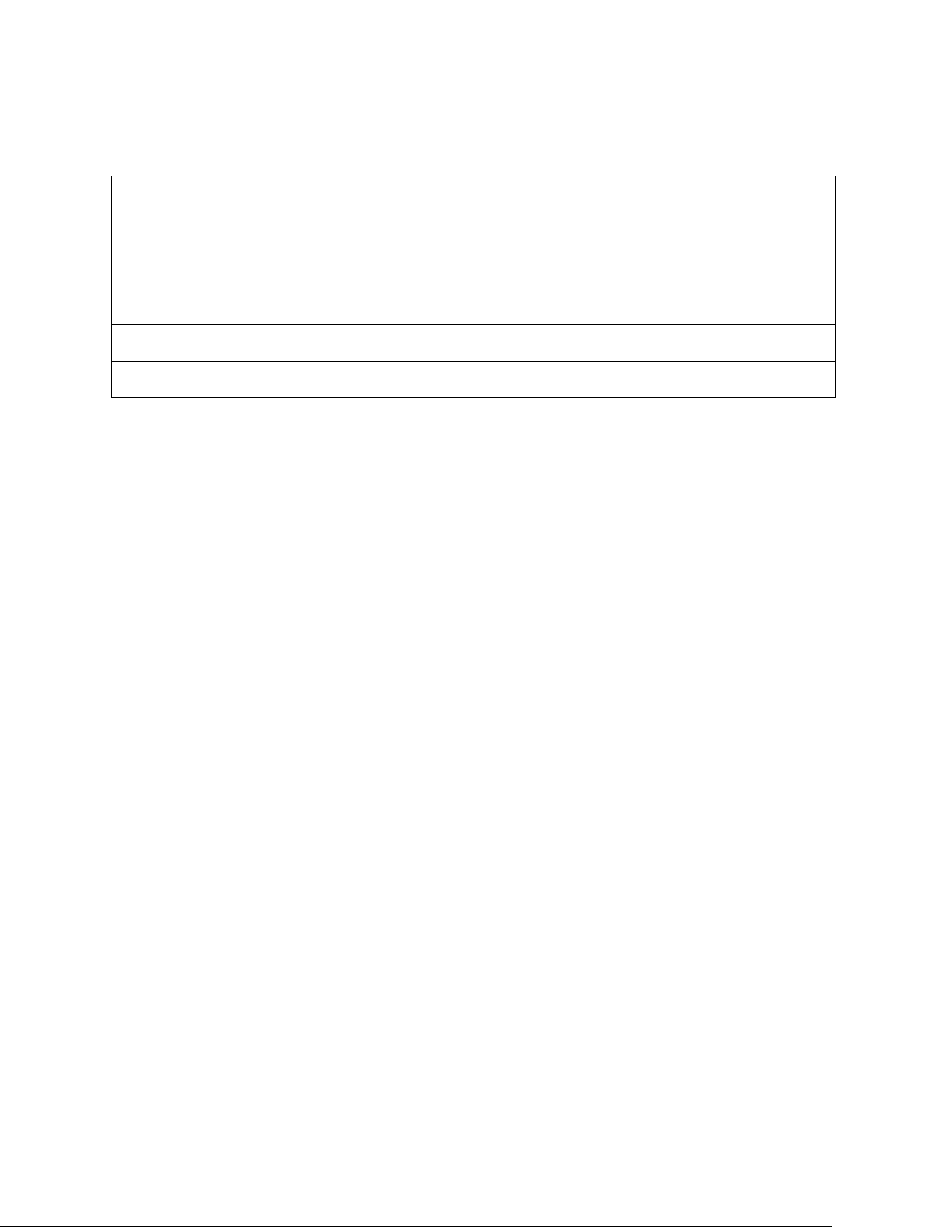
Table of Contents
INTRODUCTION .......................................................................................................................... 3
Contents ................................................................................................................................... 3
Installation Kit Contents ......................................................................................................... 6
Product Specifications ........................................................................................................... 7
Safeguards ............................................................................................................................... 9
Instructions ............................................................................................................................ 10
INSTALLATION .......................................................................................................................... 11
Step-By-Step Set Up ............................................................................................................. 11
Installation on AM-50/C-80 Ice Makers ................................................................................ 23
OPERATION ............................................................................................................................... 28
MAINTENANCE ......................................................................................................................... 30
Empty Drain Pan .................................................................................................................... 30
CO
2
Tank Replacement ......................................................................................................... 31
Cleaning and Sanitation ....................................................................................................... 31
Electrical System ................................................................................................................... 39
Transporting and Relocating ............................................................................................... 40
TECHNICAL SUPPORT ............................................................................................................. 41
Troubleshooting .................................................................................................................... 41
Leak Detector Troubleshooting ........................................................................................... 43
Support ................................................................................................................................... 43
Recycling Program ................................................................................................................ 43
WARRANTY CONDITIONS ....................................................................................................... 44
3
INTRODUCTION
Contents
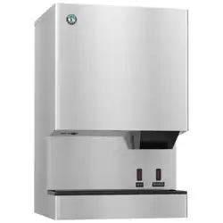
MODwater
TM
Dispenser Model DWM-20A
• DURING INSTALLATION, KEEP THE PLUGS (STEMS) INSIDE BOTH COLD AND HOT DRAINS
Cold and hot water drains should ONLY be unplugged before transporting your MODwater dispenser.
• DO NOT FLUSH FILTERS THROUGH THE DWM-20A DISPENSER
Flush or wash the filters with a separate line. Flushing the filters through the dispenser may cause the internal valves to
be compromised and fail. Your warranty will be invalidated.

4
Congratulations on your purchase!
Thank you for choosing HOSHIZAKI MODwater
TM
model DWM-20A.
The DWM-20A has the following main characteristics and features:
Multiple Options: From the left to the right: chilled sparkling water, chilled still water, hot water and cold alkaline water.
Fast: It fills bottles in seconds.
Child Safe: Avoids accidental dispensing of hot water (by enabling the Child Safety Switch).
Energy Saving: It enters stand-by mode – with button lights off, if not frequently used.
Thermal Energy Saving Switch: Turn the hot water power off if not used daily.
Alkaline Chamber: Mineral chamber included inside the dispenser.
IN ORDER TO INSTALL DWM-20A DISPENSER, YOU NEED:
1. Installation Kit: (included) a set of items for proper installation of this dispenser (see page 6).
2. Carbon Dioxide Tank (Not included): external to this dispenser (see page 8).
NOTICE
• Read the instructions in this Manual and retain for future reference.
• Product failure due to improper installation is NOT covered by the Warranty.
• The DWM-20A is for indoor use only. Do not install it outdoors.
• Due to rigorous testing performed by the Manufacturer on each of its products, the DWM-20A may
contain reasonable traces of liquid sanitizing solution inside.
• SLEEP MODE. After one hour of inactivity, DWM-20A enters SLEEP MODE to reduce energy
consumption, and all 4 touch buttons are off. To wake it up, just touch and release your finger on any of
the four buttons.
• SAFETY MODE. The green and red LED indicators are both blinking while all touch buttons are off. To
prevent accidental dispensing the DWM-20A automatically stops if more than 0.4 gallon (i.e. 1.5L) of
water is dispensed continuously, or if a button is touched for more than 30 seconds without pausing. It
also stops if there is little or no water in the pipeline flowing to the DWM-20A, or there is an internal leak.
To restart it, switch main power off and, after just 3 seconds, turn it on again.
• ENERGY SAVING. DON’T NEED HOT WATER OFTEN? Turn Hot Water Switch (RED) off and enable
Child Safety Switch (turn it to the “YES” position). Otherwise, if you don’t dispense hot water at least once
per month, the DWM-20A automatically switches hot water power off, to save energy. To get hot water
again, just touch and hold the red touch button for 15 seconds.
5
WARNING
• Connect DWM-20A to city potable water only.
• Check and comply with all local plumbing codes when performing installation.
• Check the water inlet pressure. While the dispenser id designed to withstands 80 psi maximum
inlet water pressure, the recommended inlet water pressure is 60-65 psi. Always use a water
pressure regulator (included in the installation kit) to reduce the water pressure down to 60-65 psi.
• For you sparkling water, only use carbon dioxide UN 1013 Food Grade.
• Fill water into the Hot Water Tank before switching the heater. Do not keep the heater on (i.e. by
turning the red hot water switch to on) if you do not dispense hot water at least once per month.
Save energy.
• Once the water dispenser has been installed, DO NOT MOVE IT and DO NOT TILT IT.
• If you need to move the water dispenser to another location, please check specific instructions
found on page 40.
WARNING
Only qualified service technicians should install and service the water dispenser. To obtain the name
and phone of your local Hoshizaki Certified Service Representative, visit www.hoshizakiamerica.com
.
No installation or service should be undertaken until the technician has thoroughly read this Instruction
Manual. Likewise, the owner/manager should not proceed to operate the water dispenser
until the
installer has instructed them on its proper operation. Failure to install, operate, and maintain the water
dispenser in accordance with this Manual will adversely affect safety, performance, component life, and
warranty coverage and may result in costly water damage. Proper installation is the responsibility of the
installer. Product failure or property damage due to improper installation is not covered under warranty.
Hoshizaki provides this Manual primarily to assist qualified service technicians in the installation,
maintenance, and service of the water dispenser.
6
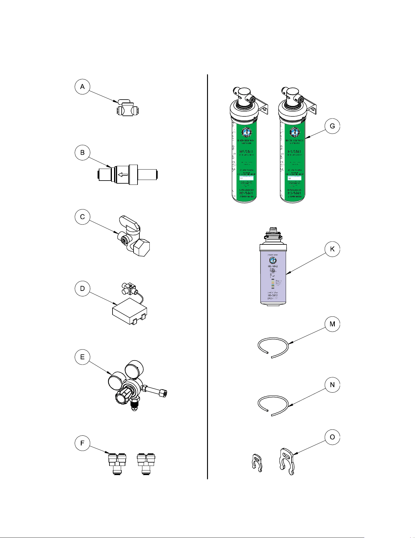
Installation Kit Contents
All-in-One Filters (2 pcs) HS-5441
3/8” Shut Off Valve
Water Pressure Regulator
Alkaline Chamber HS-5442
3/8” Angle Stop Valve
Leak Detector
3/8” Tube (20 ft.) for Water Inlet
CO
2
Regulator
1/4” Tube (15 ft.) for CO
2
Inlet
3/8” Tube 2-Way Divider (2 pcs)
Red Collet Locking Clip 1/4” and 3/8”
x5 PCS
x20 PCS
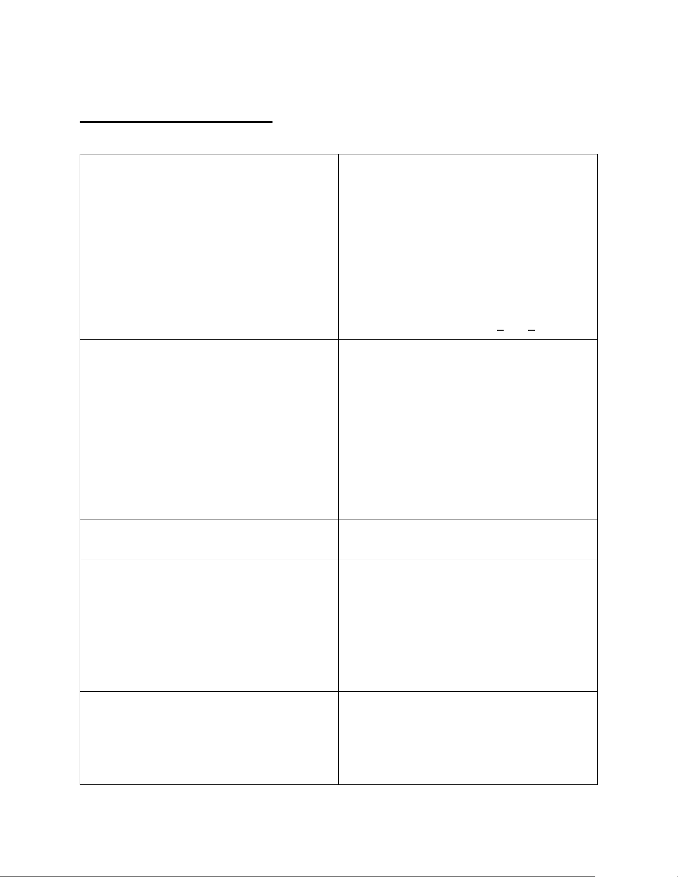
NOTICE: the performance of DWM-20A varies based on several variables including, in
particular, the temperature of the incoming water and the ambient (i.e. room) temperature. Find
above three different temperature settings characterizing Normal, Hot and Cold ambient
conditions. The performance of water dispensers also depends upon the size of the cup or the
bottle used and the sequence of dispensing (i.e. the interval of time between multiple
dispensing). This dispenser has been submitted to tests based on the standards published on
www.waterdispenserstandard.com.
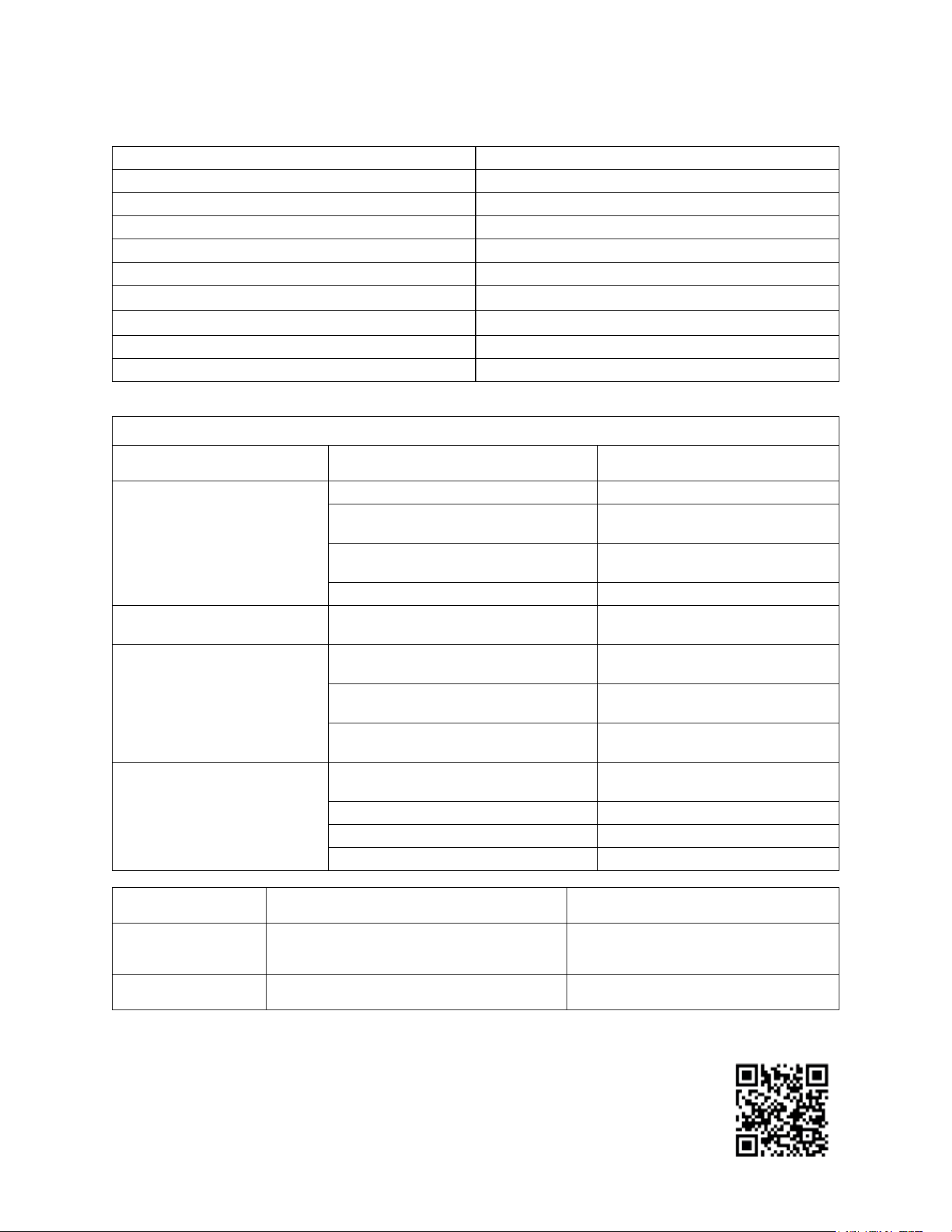
Product Specifications
Dimensions 14
7
/
8
" W x 21
1
/
2
" D x 16
5
/
8
" H
Dry / Wet Weight 72 lb. / 93 lb.
Electrical Rate 120 V / 60 Hz (Single Phase)
Maximum Current 9 A
Ambient Working Temperature 41 – 90 °F
Inlet Water Temperature 41 – 85 °F
Recommended Inlet Water Pressure 45 PSI (min) - 65 PSI (max)
Recommended Inlet CO
2
gas Pressure
※
50 PSI (min) to 65 PSI (max)
※
Water Filters Capacity 6000 Gal
Mineral Alkaline Chamber Capacity 1000 Gal
※For fine tuning of carbonation level in sparkling water, see table at page 29.
PERFORMANCE CHARACTERISTICS OF MODEL DWM-20A
SECTION PARAMETER VALUE
REFRIGERATION SYSTEM
Max Draw Capacity up to 0.9 Gal/minute (chilled water)
Max Cooling Capacity (∆T = 10°F)
20 Gal/h - Normal Ambient
Conditions
Max Volume of Chilled Water (< 40°F)
6.8 Gal/h - Normal Ambient
Conditions
Max Volume of Chilled Water (< 40°F) 5.0 Gal/h - Hot Ambient Conditions
CARBONATION MECHANISM
Max Carbonation (inlet water at 65 psi)
3.6 vol. - avg. 7.2 g/L – Normal
Ambient Conditions
HOT WATER SYSTEM
Max Dispensing Vol. at > 170°F (up to
195°F)
1.8 Gal/h Normal Ambient
Conditions
Max Dispensing Vol. at > 170°F (up to
195°F)
1.3 Gal/h Cold Ambient Conditions
Time Interval for constant hot water
temp 1 mug (8oz.)
2:30 minutes Normal Ambient
Conditions
ALKALINE CHAMBER
Max quantity of minerals dissolved in
water
40 ppm
Maximum pH (after 72 hours of rest)
10.1 pH
Average Alkaline pH 8pH to 9pH
Type of Minerals/Electrolytes K, Ca, Mg, Fe, Mn, P, Na, Zn
Normal Ambient Incoming water at a temperature of 75ºF Room temperature of 75ºF
Hot Ambient Incoming water at a temperature of 85ºF
Room temperature of 90ºF + 65%
humidity
Cold Ambient Incoming water at a temperature of 41ºF Room temperature of 41ºF
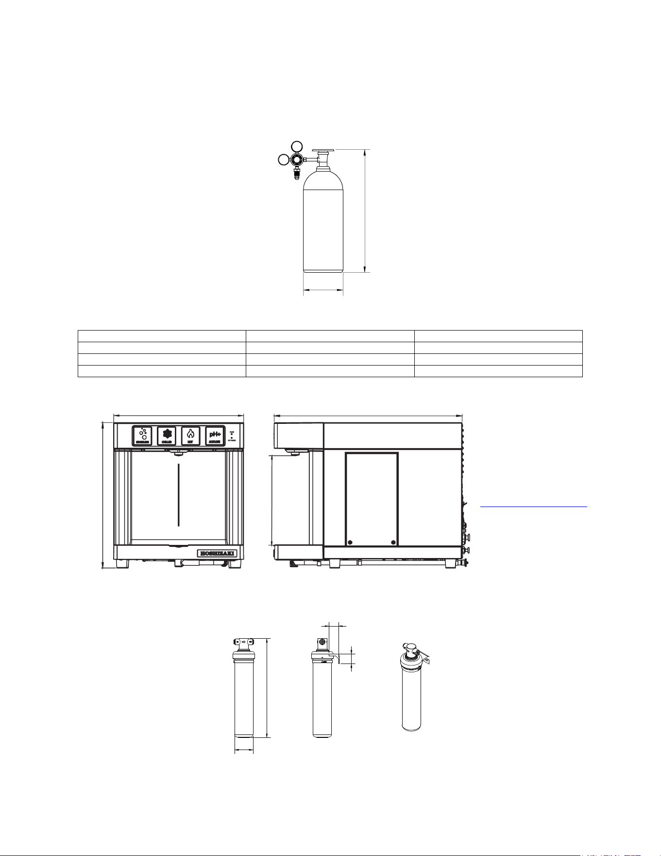
8
Dimensions of the 3 largest components to be installed:
1. CO
2
Gas Tank – UN1013 Food Grade – (Not included)
To be positioned under the counter, or at any location no more than 30 ft from the DWM-20A dispenser.
SIZE
DIAMETER
HEIGHT
20 lb. Tank
9 in.
28 in.
10 lb. Tank
7 in.
22 in.
5 lb. Tank
7 in.
17 in.
2. Model DWM-20A
To be positioned on any countertop, or on top of an AM-50 / C-80 HOSHIZAKI ice maker.
3. All-in-One filters (2 pcs.) – HS-5441 – (Included)
To be positioned under the sink, or at any location near to the main water line, no more than 10 ft. from DWM-20A.
14
7
/
8
"
21
1
/
2
"
10
1
/
4
"
16
5
/
8
"
NOTICE
for proper ventilation allow at
least 4” of space at the rear
and sides of DWM-20A. If not
possible, refer to:
www.hoshizakiamerica.com
website for alternative
installation solutions.
Height
Diameter
CO
2
Regulator
1.3"
1.6"
16.1"
3"

9
Safeguards
WARNING: TO REDUCE THE RISK OF ELECTRIC SHOCK, FIRE AND/OR PERSONAL INJURY, PLEASE READ
THIS INSTALLATION MANUAL CAREFULLY.
1. Connect and operate the DWM-20A only in accordance with the specifications shown on the label located at the
back of the DWM-20A model and in this Installation Manual.
2. Do not immerse the electric power cord, the plug, or the DWM-20A in water. Do not plug the DWM-20A into a
household extension cord. It must be plugged directly into an electrical wall outlet (110/120 VAC, 60Hz, 20 Amps).
3. Do not operate the DWM-20A with a damaged electric power cord or a damaged plug. In the event the DWM-20A
malfunctions, or is dropped or damaged in any manner, unplug it immediately and return it to the manufacturer for
repair.
4. Do not place the DWM-20A, its electric cord, or plug on or near stoves or other hot surfaces.
5. Always unplug the electric power cord when the DWM-20A is not in use for an extended period, when it is relocated,
or before cleaning it.
6. Leave at least a 4-inch gap on all lateral sides between the DWM-20A and the wall to assure sufficient air circulation
for proper ventilation and efficient cooling of the water dispenser’s refrigeration system. Do not install the DWM-
20A inside a cabinet because without proper air-circulation the water dispenser’s refrigeration system will fail.
Alternative installation solutions are possible: refer to www.hoshizakiamerica.com
to find out more.
7. Children and people with mental disabilities must be supervised by a person who is responsible for their safety
when using the DWM-20A, because it can dispense water at a very high temperature. ADULT SUPERVISION
REQUIRED.
8. To avoid potential hazards and personal injury, never attempt to open/disassemble the DWM-20A by unscrewing
panels/covers: there are no user-serviceable parts inside! In case of malfunction, call the Manufacturer using the
toll-free customer service line. Repairs of DWM-20A must only be performed by the Manufacturer or its qualified
service personnel to avoid potential hazard and electric shocks. The Manufacturer warranty will be automatically
invalidated if non-authorized personnel service the DWM-20A. Call toll-free at 1 (800) 233-1940.
9. Any use of non-original parts (i.e. parts not provided by the Manufacturer), including third-party parts, could lead
to a permanent malfunction or a failure of the DWM-20A, property damage and/or personal injury, including death.
10. Using third-party filters or other filtration systems for the DWM-20A water dispenser other than original filters may
result in a permanent malfunction of the dispenser and may also cause personal injury. Furthermore, it will
invalidate the manufacturing warranty on the DWM-20A.
11. If any component of the DWM-20A is misused or used incorrectly, the water dispenser may fail and cause property
damage and personal injury, including death from electric shock. Misuse of the DWM-20A may cause deterioration
of the quality or contamination of the materials used in the DWM-20A. Connecting the water dispenser to a supply
of contaminated water may result in serious personal injury. Only connect the DWM-20A, through its own external
filtration system, to a potable water supply.
12. Water pipe connections and fixtures directly connected to a potable water supply shall be seized, installed, and
maintained in accordance with federal, state, and local codes.

10
Instructions
1. Make certain that installation of the DWM-20A model complies with all federal, state and local laws and regulations
as well as with your building codes, office/apartment or condo provisions, rules or regulations.
2. In the installation of DWM-20A you must only use HS-5441 filtration system. The Manufacturer is not responsible
for any misuse or modification of HS-5441 filtration system and accepts NO liabilities if the DWM-20A is used with
different filtration systems. In addition, the use of non original filters invalidates the Manufacturer
3. on the DWM-20A water dispenser.
4. Do not connect the DWM-20A dispenser and its filtration system to a water supply that is microbiologically unsafe
or of unknown quality without adequate pre-treatment and disinfection. Connect HS-5441 filtration system to the
city potable water only.
5. If the DWM-20A is left unused for more than 3 days, dispense at least one bottle of water from each water type. If
left unattended for more than 30 days, replacement of its filtration system and of its alkaline chamber is
recommended before starting to use the DWM-20A again.
6. The DWM-20A dispenser must be connected to a cold water supply with a pressure of at least 45 psi measured
on a 3/8” section tube. A very low external water pressure (at or below 40 psi) or a very low water flow rate (below
1 gallon/minute) will significantly reduce or hamper the performance of the DWM-20A and its ability to properly
carbonated sparkling water. If the water pressure is low, please use the booster pump as indicated in the Parts
Manual (order separately).
7. The DWM-20A is designed to operate up to the maximum allowed water pressure for a residence or a commercial
building, which is 80 psi (552 kPa). However, the recommended maximum water pressure is 60-65 psi. To reduce
the water pressure, use the water pressure regulator provided in the installation kit.
8. Do not use the DWM-20A outdoors. The recommended room temperature, for indoor use, is comprised between
41°F and 90°F.
9. When the filtration system indicator (green light – top right) starts blinking (on/off) it means that the HS-5441 filters
and the HS-5442 alkaline chamber have reached the end of their lifespan, and MUST be changed in order to
prevent quality deterioration of your drinking water and/or clogging of the system. It is recommended to replace
the HS-5441 filters and the HS-5442 alkaline chamber as soon as possible when the green light indicator starts
blinking or every 6 months, whichever comes first.
DUE TO THE FACT THAT THE MANUFACTURER MAY NOT KNOW THE QUALITY AND THE
PERFORMANCE CHARACTERISITCS OF ANY POSSIBLE ALTERNATIVE FILTRATION SYSTEMS IN THE
MARKET, PLEASE NOTE THAT THE MANUFACTURING WARRANTY OF THIS DISPENSER BECOMES
NULL AND VOID SHOULD YOU USE FILTER(S) OTHER THAN THE HS-5441.
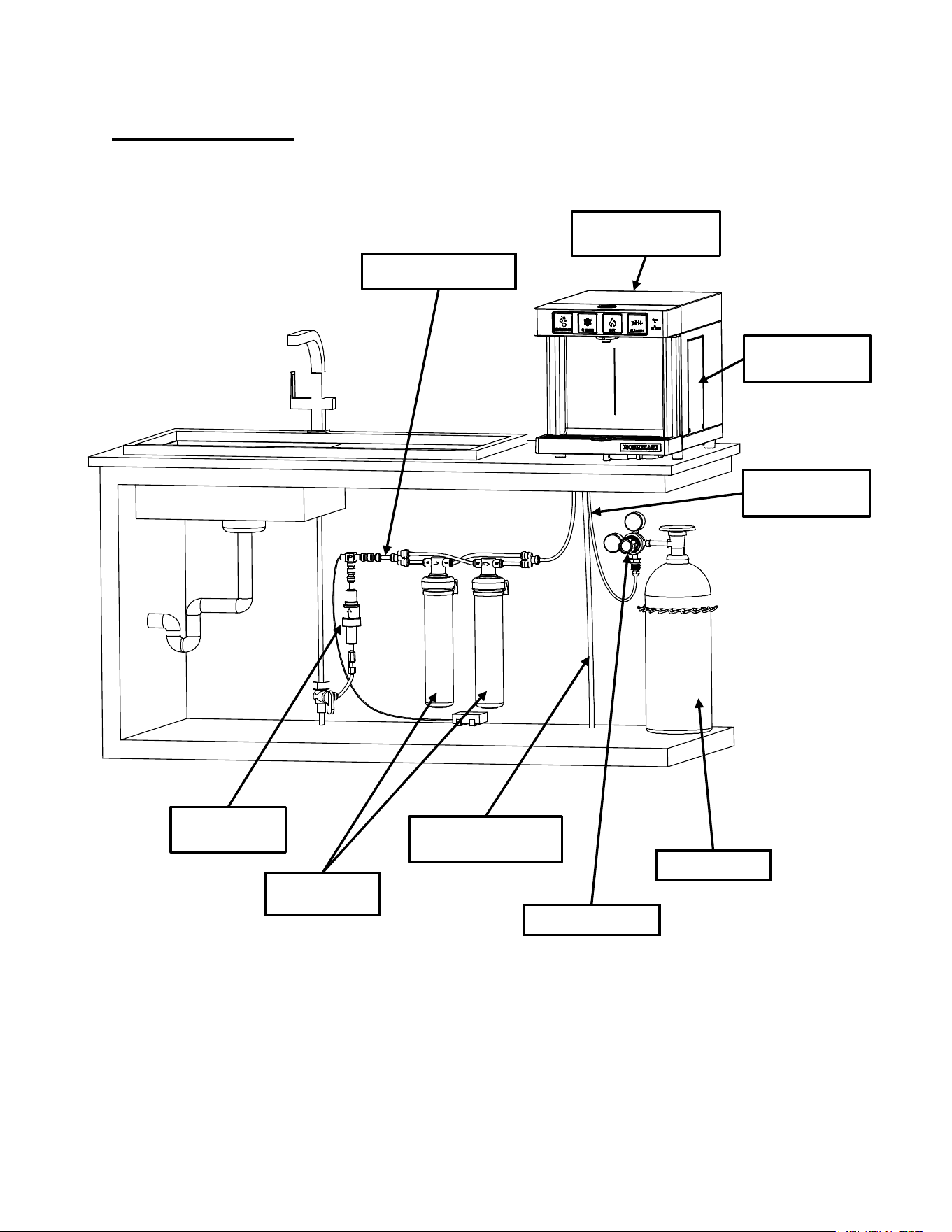
11
INSTALLATION
Step-By-Step Set Up
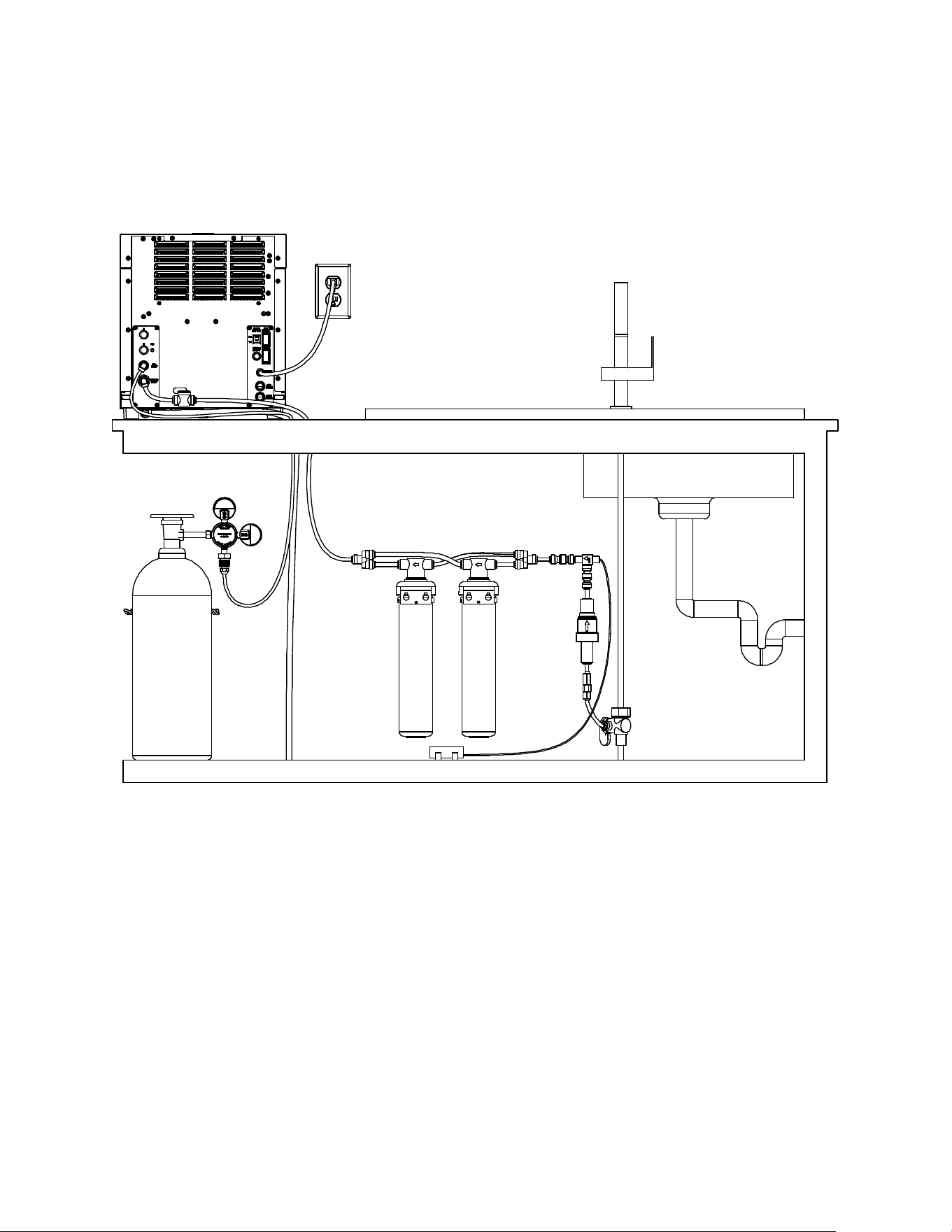
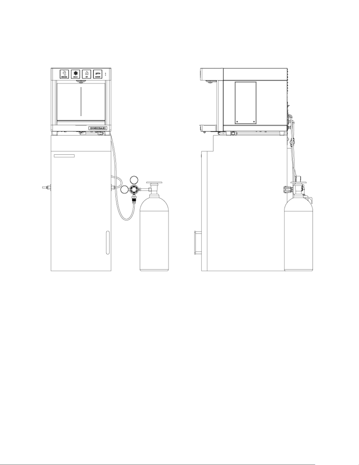
COMPLETED INSTALLATION ON A COUNTERTOP
CO
2
Gas Regulator
DWM-20A
DISPENSER
3/8” Water Line Tubing
Alkaline Chamber
(HS-5442)
Water Pressure
Regulator
1/2" Drain Line Tubing
*SOLD SEPARATELY
CO
2
Gas Tank
1/4" CO
2
Gas Line
Tubing
All-in-One filters
(HS-5441)
12
General Instructions:
• The DWM-20A model is designed to be located on any countertop, or on a Hoshizaki C-80/AM-50 ice maker as
indicated on the following section (see page 23).
• In case of installation on a counter, the DWM-20A must be placed on a sturdy, uniform surface capable of
withstanding, at least, 93 lb. of weight. A kitchen countertop is an ideal place. Unpack the DWM-20A model and
place it on a counter, next to an electrical power outlet, exactly where it is supposed to be permanently installed.
• Locate a water line within 10 feet of the DWM-20A. Make sure the water supply you intend to connect the DWM-
20A to is cold and is not coming from a water heater or boiler.
• Allow 4" of space at rear and sides of DWM-20A for better ventilation. Never place the DWM-20A inside a closed
cabinet without proper ventilation. In case this requisite may not be fulfilled, go on www.hoshizakiamerica.com
web site for alternative installation solutions.
• IMPORTANT: Before beginning the installation process, insert the alkaline chamber (K) by unscrewing the lateral
panel of the DWM-20A. Refer to diagrams on pages 36 and 37 for details about how to perform this operation.
• The All-in-One filtration system (included) and the CO
2
gas tank (not included) should be installed under the
counter.
• In order to connect the dispenser to its external filtration system (with the 3/8” flexible plastic tube provided in the
installation kit) and to the CO
2
gas tank (with the 1/4” flexible plastic tube provided in the installation kit), a 3/4”
hole might be necessary to be drilled on the countertop, in a location corresponding to the back of the dispenser.
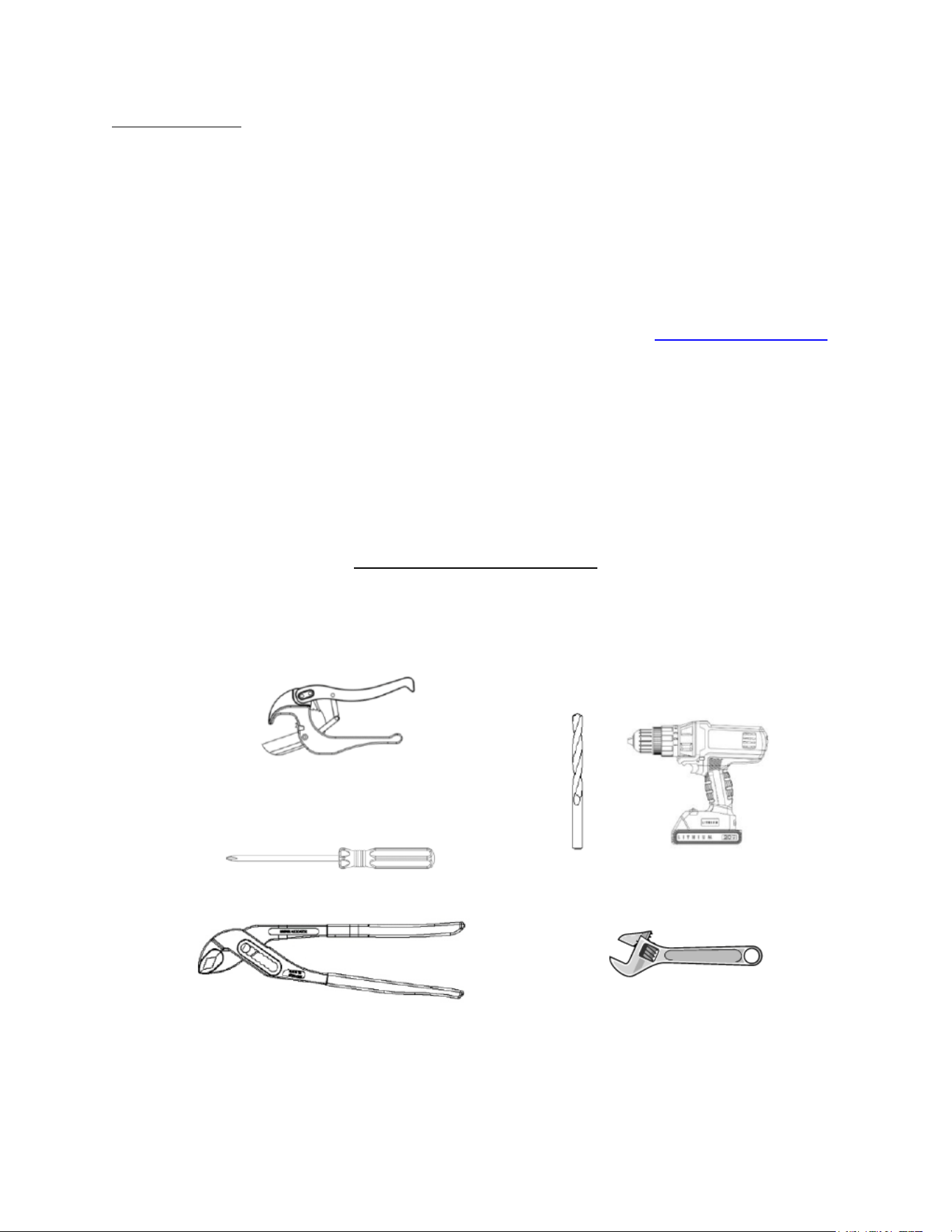
List of Necessary Tools (Not Provided):
Tube Cutter
Screwdriver
Tongue and Groove Pliers
Electric Drill
1
/
8
" Drill Bit and, for
granite, a Milwaukee One-Piece
Hole Saw Diamond plus
3
/
4
" &
1
/
2
"
Adjustable Wrench
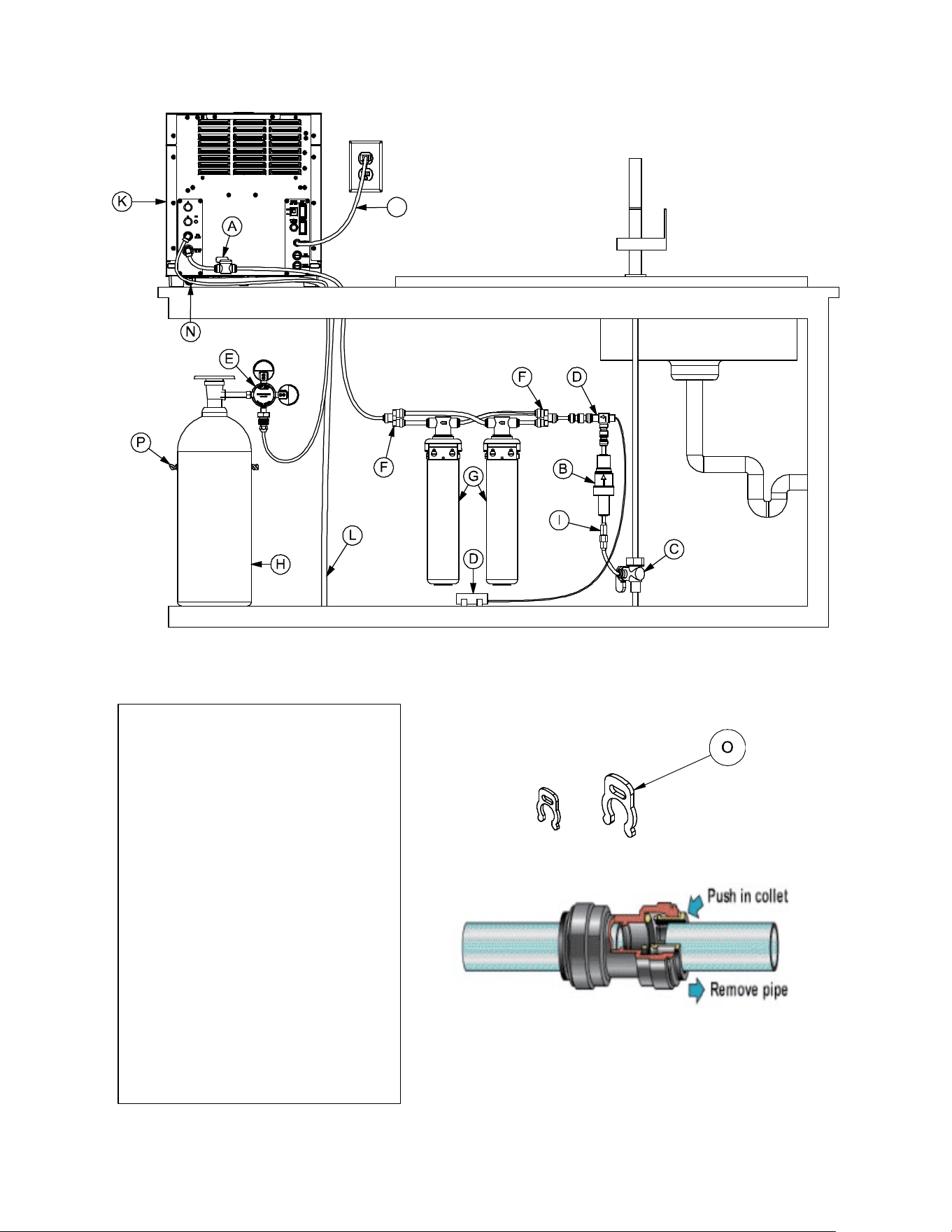
13
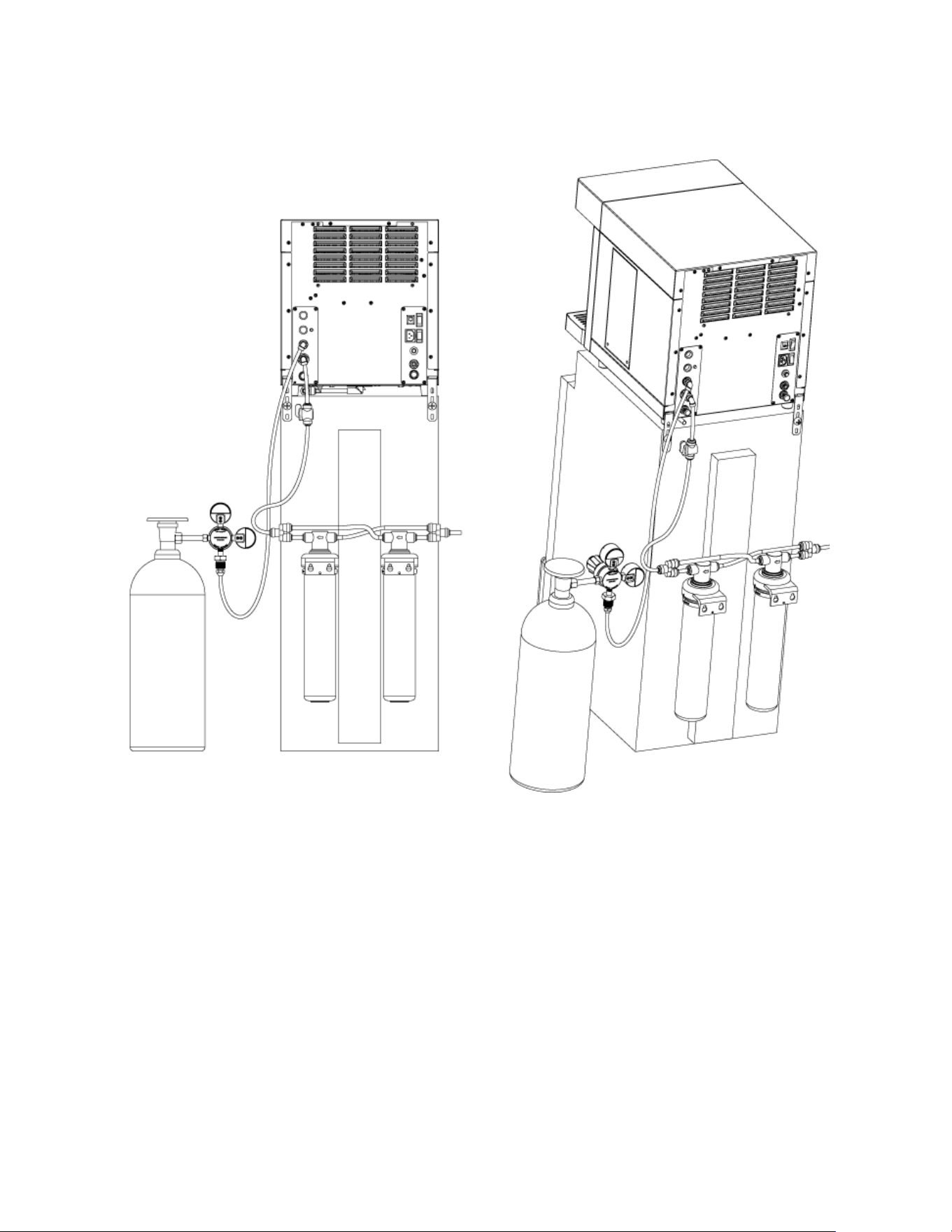
Lock each John Guest Quick Connect
with Collet Locking Clip
J
A. 3/8" Manual shut off valve
B. 65PSI 3/8” Pressure regulator
C. 3/8" Angle stop valve
D. Leak Detector
E. Double Gauge CO
2
Regulator
F. 3/8" Tube 2-way Divider
G. Double All-in-One Filter
H. CO
2
Gas Tank
I. Flow Prevention Valve (ASSE 1032)
J. Power Cord
K. Alkaline Chamber
L. 3/8" Drain Tube
M. 3/8" Water Tube
N. 1/4" CO
2
Tube
O. Red Collet Locking
P. CO
2
Tank Restraint
BACK VIEW OF A COMPLETED INSTALLATION ON A COUNTERTOP
x5 PCS
x20 PCS
Red Collet Locking Clip 1/4” and 3/8”
14
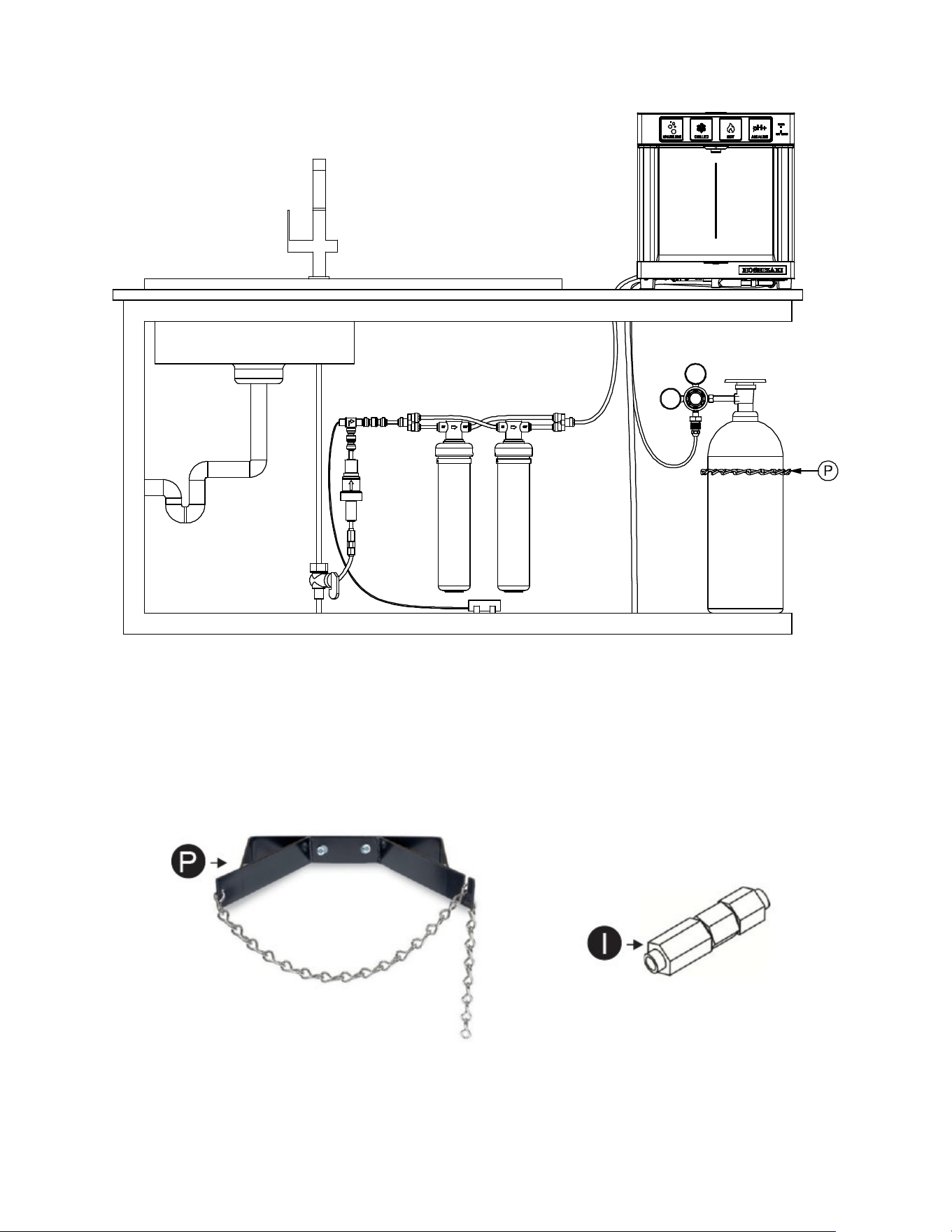
• Unpack the two All-in-One filters. Procure the CO2 gas tank from a local CO2 supplier of choice. Make sure that
the CO2 tank is labeled Carbon-Dioxide UN1013 Food Grade. Check that there is sufficient space under the
counter to place all the components of the installation kit as listed on page 6. Otherwise select another suitable
location for either the filters or the CO2 tank. Filters and/or CO2 tank can be located several feet away from the
dispenser (DWM-20A unit) (see page 8). Before starting, check dimensions of largest components on page 8.
CO
2
Tank Restraint
(Not Included)
Backflow Prevention Valve ASSE 1032
(Not Included)
FRONT VIEW OF A COMPLETED INSTALLATION ON A COUNTERTOP
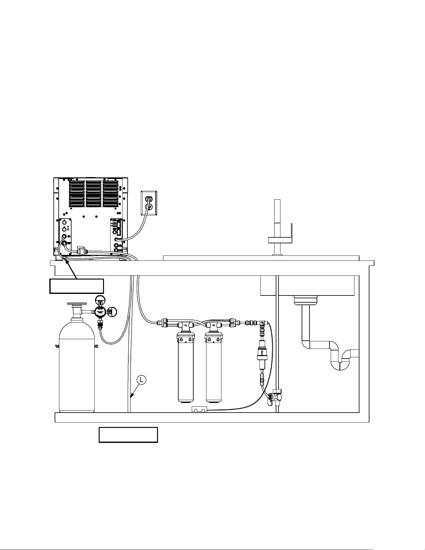
15
• IMPORTANT: connect the drain pan. The drain pan comes connected to a drain pipe that runs underneath the
dispenser and can be connected to a drain by a flexible plastic tube connected to the back of the DWM-20A
dispenser. If there is not enough downward slope for the drain line, please install an accessory drain pump to
ensure water does not back-up in the drain line. Remove the two (2) black rubber plugs at the bottom of the
drain pan and at the end of the drain tube.
• Alternatively, if the location where the dispenser is installed has no drain, you can go “drainless” and use the
drain pan as a “drip tray.” You must detach the metal pipe underneath the drain pan (by pushing down the silicon
connector) and leave the plug at the bottom of the drain pan. The drain pan must be emptied periodically, or
when it is full. NOTE: Please be sure not to pour non-water liquids in the drain pan as they can create unsanitary
conditions.
• The DWM-20A drain pan can be connected to a drain through a flexible plastic tube (1/2”) as per picture (not
included).
From drain pan
Drain to the floor
BACK VIEW
16
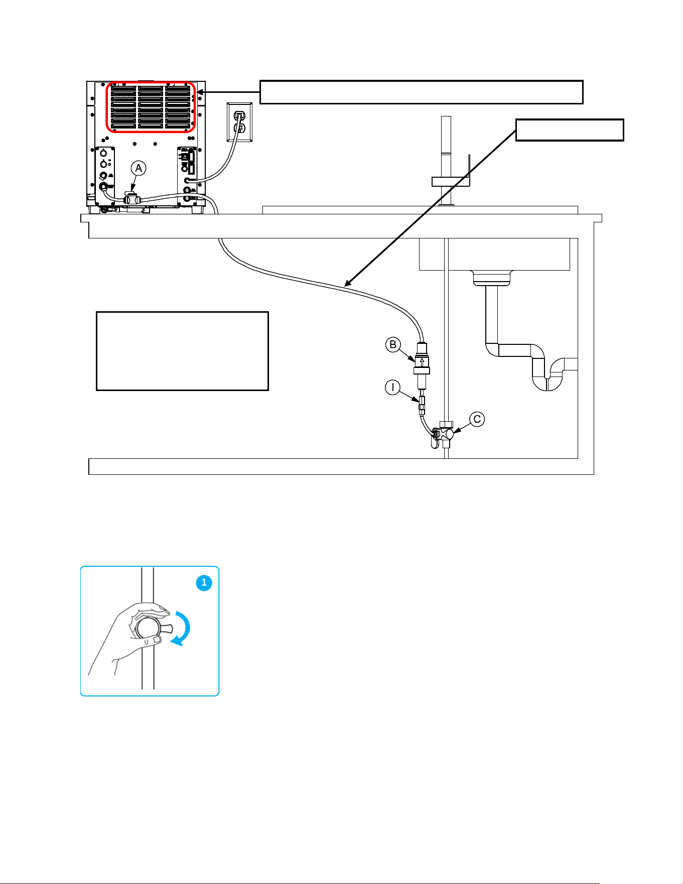
• Prepare a temporary water line to connect the water dispenser (DWM-20A unit):
1. Locate and close the main valve for COLD water under the sink (turn it right
completely), (fig 1).
BACK VIEW
C. 3/8” Angle Stop Valve
B. 65 PSI 3/8” Pressure Regulator
I. Flow Prevention Valve (ASSE 1032)
Warm air blows out from the back 5 minutes after the DWM-20A has started
Temporary Water Line
17
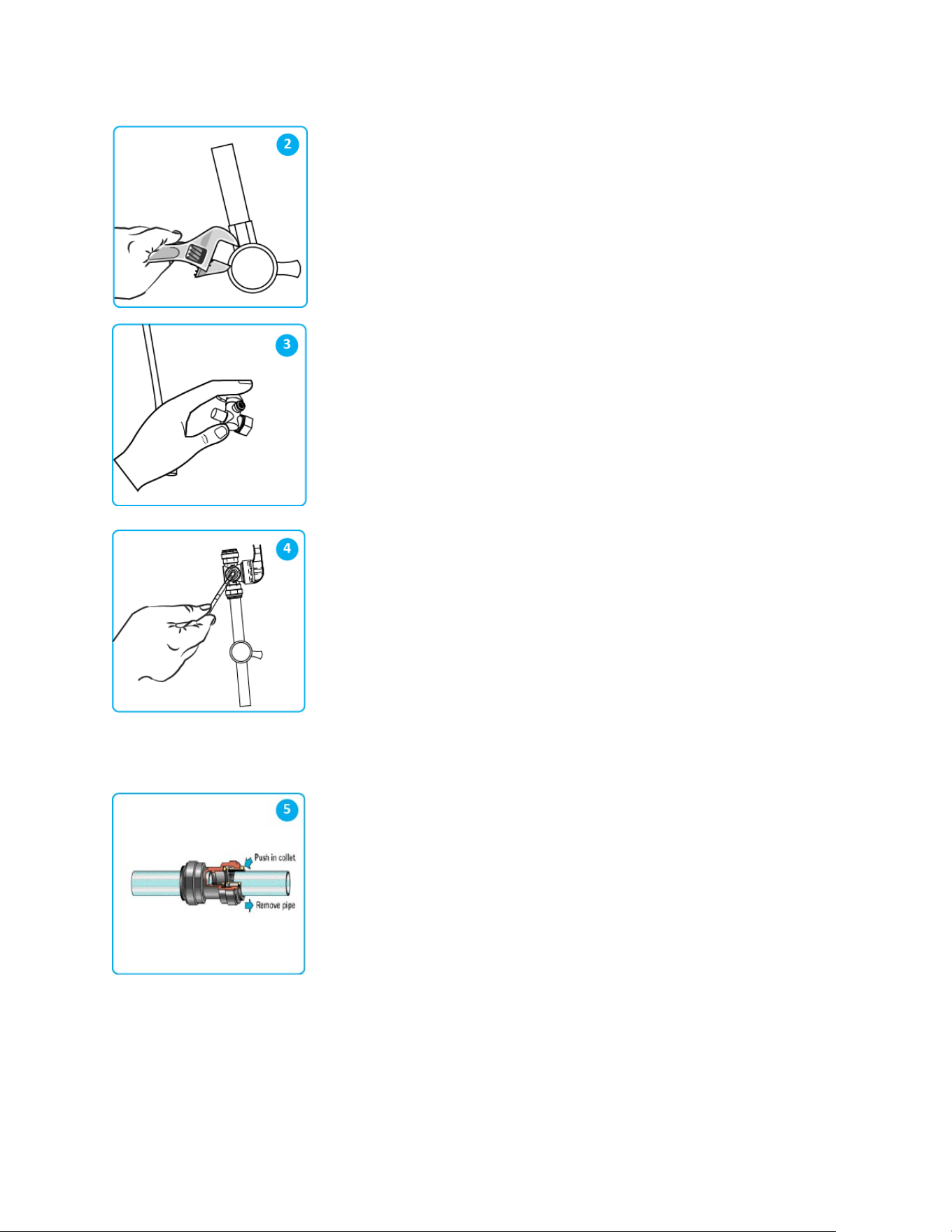
2. Using a pipe wrench, loosen the nut and disconnect the water line at the main
valve, (fig 2).
3. Next, install the “Angle Stop Valve” (C), as shown, (fig 3).
4. Locate the 3/8” flexible tube in the installation kit. Cut a short tube section to
connect the angle stop valve to the other components of the installation kit, (fig 4).
Then install the “ASSE 1032” backflow prevention valve (I), the water pressure
regulator (B) and the shutoff valve (A).
※Install (C), (I) and (B) close to each other. Install (A) close to the DWM-20A on
the countertop. Make sure (C) is installed on the cold water source under the sink,
NOT the hot water source which is often located next to the cold! Insert the other
extremity of the 3/8” tube in the elbow quick-connector in the “WATER INLET” port
located at the back of the DWM-20A. IMPORTANT: open both valves (C) and (A)
so that water from the temporary water line can enter the DWM-20A.
5. TIP: To connect the 3/8” flexible plastic tube to the other components of the
installation kit, simply push the tube into the quick-connect fitting until it stops. Then
pull out the tube to check if it is secured in its position and it is properly connected.
To disconnect it, first push in the collet as shown in the fig 5. Next, with the collet
held in position, remove the tube by pulling it away from the collet as shown.
WARNING: AS DIRECTED IN THE INTERNATIONAL PLUMBING CODE OF THE INTERNATIONAL CODE
COUNCIL AND THE FOOD CODE MANUAL OF THE FOOD AND DRUG ADMINISTRATION (FDA), THIS
DISPENSER MUST BE INSTALLED WITH ADEQUATE BACKFLOW PREVENTION TO COMPLY WITH FEDERAL,
STATE AND LOCAL CODES. FOR MODELS INSTALLED OUTSIDE THE U.S.A., YOU MUST COMPLY WITH THE
APPLICABLE PLUMBING/SANITATION CODE IN YOUR AREA.
18
• Locate the gas tubing (1/4”) as found in the installation kit.
• Attach a CO
2
regulator (as provided in the installation kit) to the external CO
2
canister (not provided) by turning the
nut to the right while holding the regulator. IMPORTANT: Ensure that the main valve on the external CO2 canister
is completely closed.
• Connect the CO
2
regulator using the 1/4” CO
2
tube, to the elbow quick connector (1/4”) in the “CO
2
INLET” at the
back of the DWM-20A appliance.
• Open the main valve on the external CO
2
canister very gently to avoid fast release of gas.
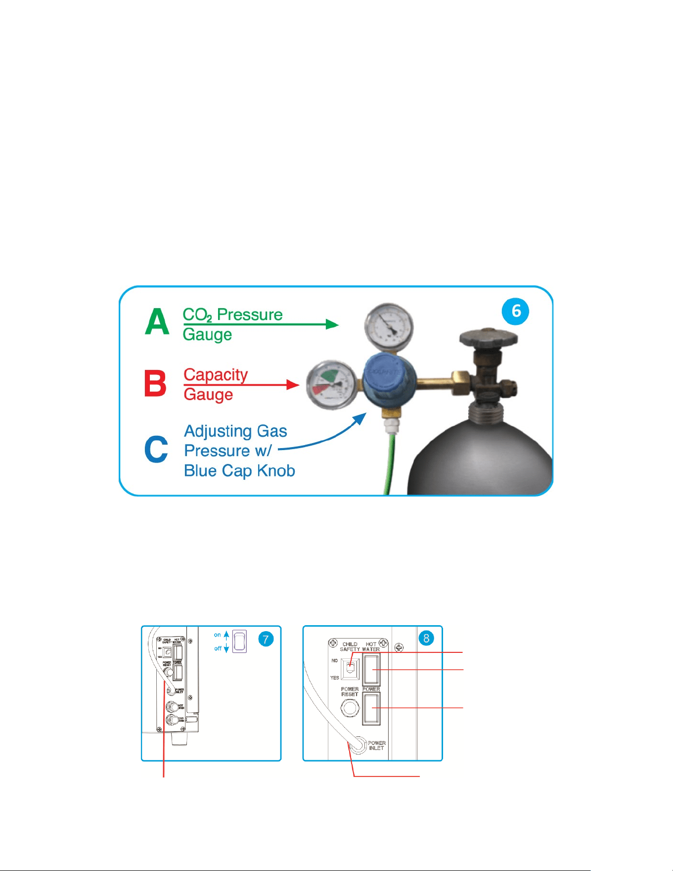
• Then, use the CO
2
regulator (see installation kit) to adjust the pressure. Turn the blue handle knob located on the
front side of the CO
2
regulator. Set the pressure to your desired fizziness level (typically around 55 to 65 psi). After
the pressure is set, push the blue knob in, to lock the arrow right at the selected gas pressure.
• See Figure 6 below. For fine tuning go on page 29.
WARNING: THE CO
2
TANK MUST BE SECURED WITH A CHAIN OR RESTRAINT (P) IN AN UPRIGHT POSITION
AS INDICATED ON PAGE 14 OF THIS MANUAL.
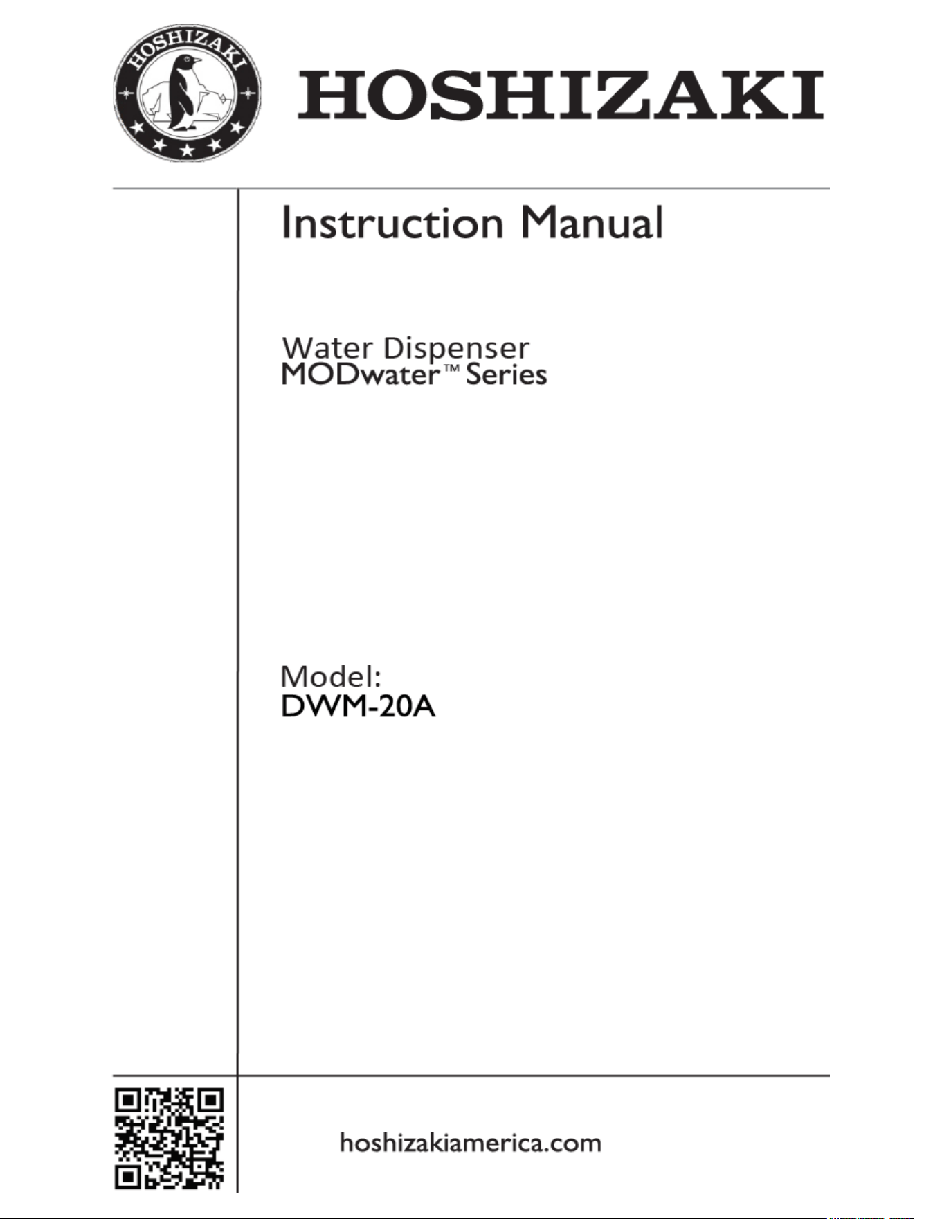
• At this point, locate the main electrical power socket and the main electrical power supply switch at the back of
the DWM-20A, plug in the dispenser and switch the main electrical power ON (see fig 7 and fig 8 below).
IMPORTANT: do not turn on hot water power yet (the red switch behind the DWM-20A).
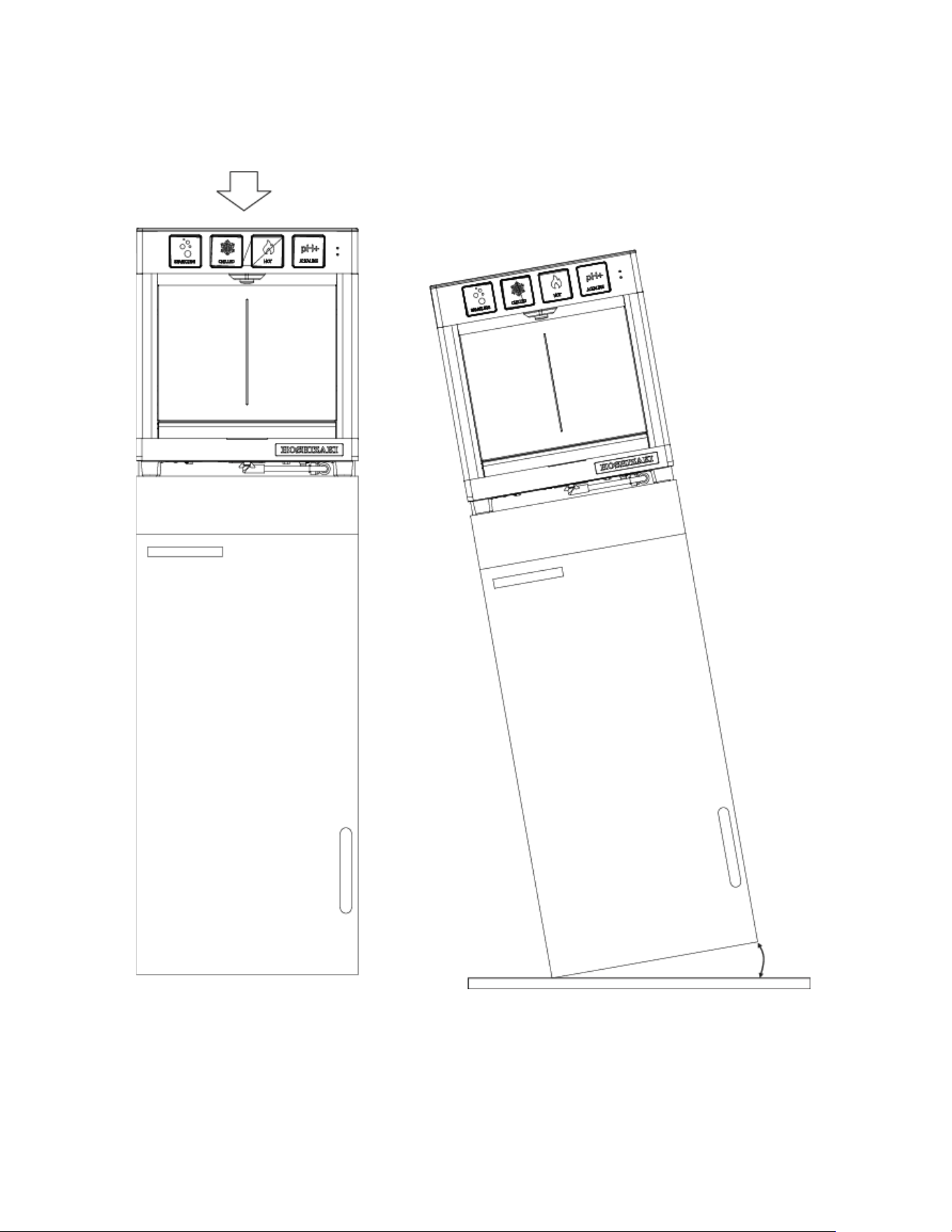
IMPORTANT: if the DWM-20A was NOT transported upright, make sure the DWM-20A has sat still in its position
for at least 2 hours before turning on main power. This is to ensure the refrigerant has had time to settle.
Electrical Cable
Main Electrical Power Socket
Main Power Switch
Hot Water Switch
Child Safety Switch

19
• With power on, after one (1) minute, two touch button lights - the green-sparkling and the white-alkaline - will
start blinking. Touch and hold both of them – contemporarily – for three (3) seconds, until ALL all four button
lights (green, blue, red, and white) will start blinking, indicating water is flowing into the dispenser.
• If valves (A) and (C) are both opened, the flow of water inside the DWM-20A will be audible, which indicates the
automatic filling of the refrigeration system has been activated. This automatic filling process of the internal
chiller of the unit may take up to ten (10) minutes. Wait. IMPORTANT: When the water dispenser is ready, all
the touch button lights will stop blinking and stay illuminated.
• The unit’s compressor starts after another five (5) minutes. Check the air temperature behind the dispenser’s
grid. The air blowing through the grid should be warm (red circle area in the picture on page 16).
• Touch the Alkaline button (white) and dispense alkaline water. Initially, the alkaline water may be gray in color
because of the granular activated carbon contained in the alkaline chamber. After completely flushing the
alkaline chamber HS-5442, the alkaline water dispensed is clear and transparent.
• Touch and hold the red-hot touch button until water comes out from the hot water nozzle (located just behind the
main nozzle). Please note that the nozzle for the hot water is separated from the nozzle of alkaline, chilled and
sparkling water in order to minimize splashes and to reduce flow rate (for safety reasons). If by touching the red
button hot water is not dispensed, it is probably due to the Child Safety Switch located at the back of the
dispenser being switched on (i.e. the switch is positioned on its “YES” position). The Child Safety Switch will
prevent children from accidentally dispensing hot water by pressing the red button. Therefore, disabling the Child
Safety Switch will allow you to dispense hot water by touching the red button. This will also activate the red-light
indicator “HOT WATER” located at the right corner of the front of the dispenser. When the red light is illuminated
- WARNING sign - the DWM-20A is enabled to dispense hot water. In order to dispense hot water, first the
internal HOT WATER TANK MUST BE FILLED UP: touch the red button until the hot water tank is totally filled
and water starts flowing out of the nozzle.
• Next turn on the hot water switch (red switch) located behind the DWM-20A model (see fig 8). It takes almost ten
(10) minutes for the water in the internal hot water tank to reach the maximum temperature.
• Now dispense some Chilled and Sparkling (even without adjusting the CO
2
gas for optimal carbonation level),
and check if the dispenser is working properly. IMPORTANT: for fine tuning of the dispenser, wait unit the
installation is completed and the water is very cold. If the water is not cold enough, carbonation will not occur!
• At this time, while the dispenser has started and its refrigeration and heating systems are working, you might
need to drill a 3/4" hole on the countertop in proximity of the back of dispenser to connect the DWM-20A unit with
its filtration system and its CO
2
tank. Use a one-piece hole saw or equivalent tool.
• At this point, close the Angle Stop Valve (C), and dispense some alkaline water for 5 seconds in order to release
the water pressure inside the temporary water line.
• Shut off the valve (A) behind the Water dispenser but KEEP the electrical power on. Now you can remove the
temporary water line.
• Leave the water dispenser powered on so that its refrigeration system can work during the time the filtration
system is installed. Then, when the installation is completed, you can easily check the temperature of the chilled
water and the carbonation of the sparkling water. IMPORTANT: Do not move the water dispenser since its
refrigeration system is now full of water and might overflow. If you need to slightly move the DWM-20A to its final
position, pay extreme attention. The dispenser is quite heavy now (93lbs), its refrigeration is full of water and
any sudden movement might produce an internal water overflow and small flooding on the countertop. Avoid
this. Do not ever incline the DWM-20A.
• Install the leak detector tee (D) close to the water pressure regulator (B). Do not activate leak detector by
inserting its alkaline battery until the installation is complete.
• Connect (D) & (F) (i.e. the 3/8” 2-way divider), which is the inlet of the two All-in-One filters HS-5441. The two
filters shall be connected “in parallel”. Connect the temporary line from the other 3/8” 2-way divider (the outlet
port of the double All-in-One filters) directly to the sink to allow flushing of the filters. Open the angle stop valve
(C) and keep it open until clear water is dispensed through this temporary line. IMPORTANT: the complete
flushing of the external filters may require up to five (5) gallon of water to pass through.
20
• When completely clear water is dispensed through the double All-in-One filters, close the angle stop valve (C)
again, and remove the temporary water line.
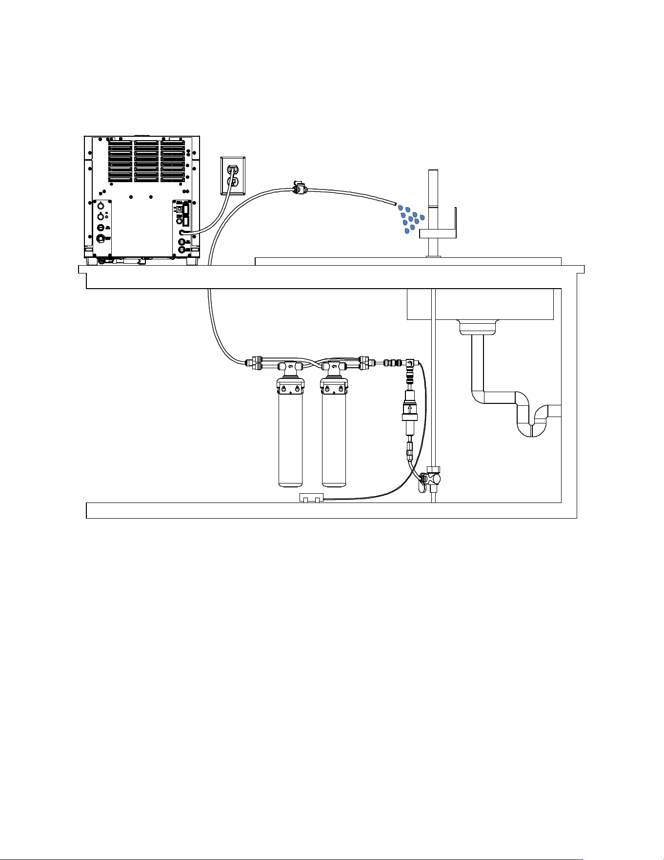
• Run a line from the back of the dispenser to the 3/8” 2-way divider which is connected to the filters’ outlet port.
• Now that the entire water line is connected, as per the picture on the next page, open the angle stop valve (C)
and also the shutoff valve (A).
• IMPORTANT: make sure DWM-20A is fully connected to the water line and to the CO
2
line and dispense some
water from DWM-20A. Now pull all the lines: the 3/8” water inlet line, the 1/4” CO
2
gas line and, also, the 1/2”
water drain line, if present) in order to check if they are all properly connected with the various John Guest
connectors. Make sure there are no leaks. Insert collect locking clips 1/4” and 3/8” as appropriate at any junction.
• Insert the battery (included) into the water leak detector. Use a small piece of wet fabric or wet paper towel in
order to test the leak detector by using the wet fabric or paper towel to touch both electrodes and close the
circuit. Check that the leak detector gets triggered correctly by listening for a loud beep. To reset the leak
detector, press and hold its reset button for five (5) seconds until the water solenoid valve of the leak detector
opens.
• Make sure that the entire installation area is clean and dry. Cut a small square of (completely dry) paper towel,
fold it and position the paper towel under the electrodes of the leak detector: if the paper towel gets wet due to a
flooding, the leak detector will activate and the solenoid valve will close the water line. Then the leak detector will
BACK VIEW
21
start beeping loudly. However, thanks to the paper towel wrapped around, a small spill from a glass of water or
from the drain pan would not be sufficient to trigger the leak detector.
• Carefully position the leak detector under the counter, close to the double All-in-One filters, or in an area where
potential flooded water would naturally accumulate, (see diagram below).
• Now the installation is complete, and it is time for setup and fine tuning. Place a bottle or container on the drain
pan. Dispense alkaline water (white button) until the dispensed water is clear of carbon particles. NOTE: It is
normal that the first two gallon of mineralized alkaline water appears black or milky in color. Wait 10 minutes.
Dispense two gallons more until the water is completely clear. Repeat the process after waiting another 10
minutes until the alkaline water is totally transparent.
• Dispense 16 oz. of chilled (still) water (blue button). If the DWM-20A has been turned on for more than one hour,
the chilled water now should be ice-cold.
• Next, dispense 16 oz. of sparkling water (green button). Make sure the regulator has the arrow in the green
region (see fig 6 on page 18). For fine tuning of the carbonation level, refer to the table on page 29.
• Next, dispense hot water (red button). Check if the red LED light top left is on. If the hot water tank heater has
been on for more than 10 minutes, the hot water now should be boiling-hot.
BACK VIEW
22
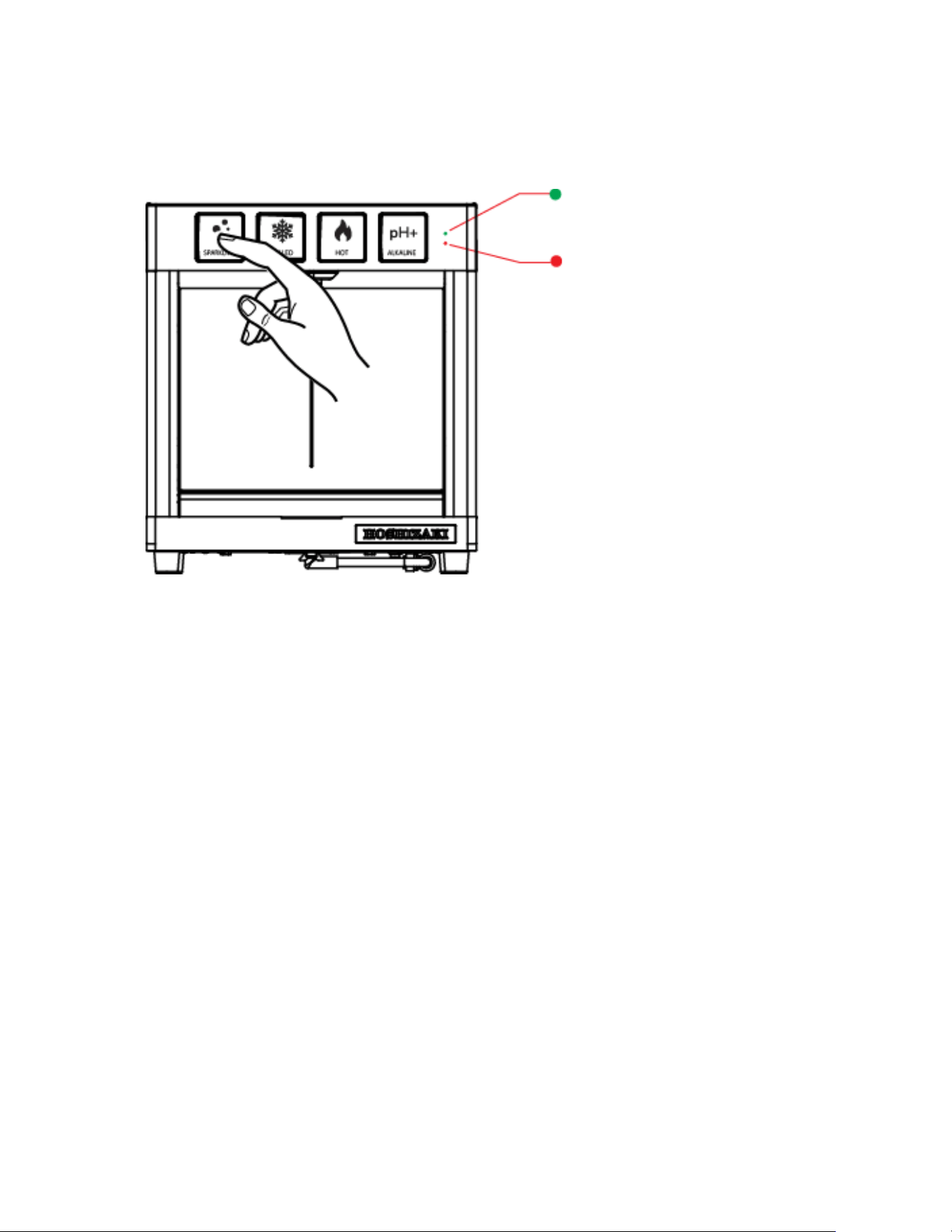
• If you have installed the DWM-20A filtration correctly, the green light indicator “FILTER” (top right) should also be
solid green at this point.
FILTER LIFE (GREEN)
if blinking, replace the filters
HOT WATER AVAILABILITY (RED)
If off, disable child safety switch at the back
23
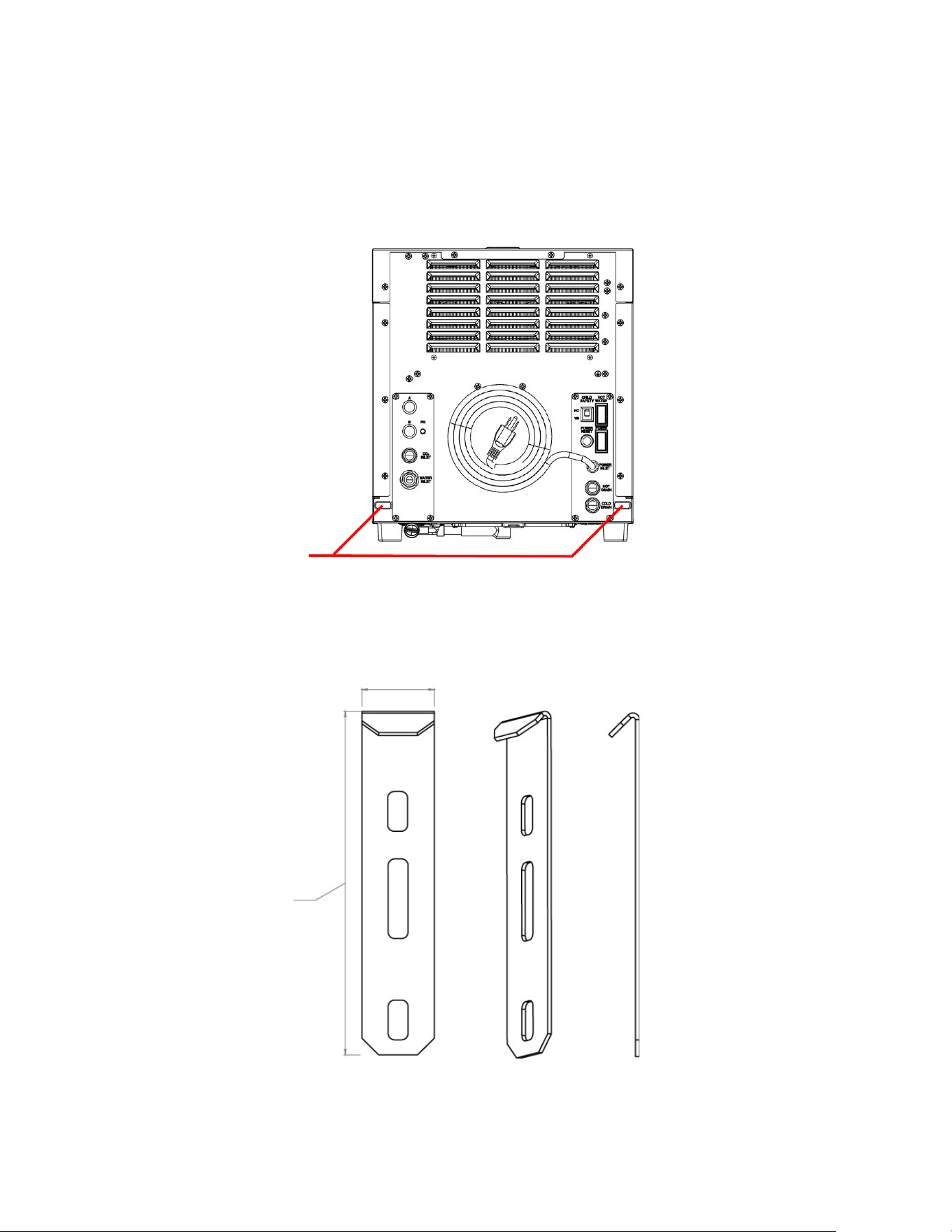
Installation on AM-50/C-80 Ice Makers
The MODwater DMW-20A can also be mounted on Hoshizaki AM-50 or C-80 undercounter ice makers. The base of
the DWM-20A is designed to perfectly fit on top of these ice makers and can be secured by using two mounting
brackets, provided separately as an accessory. The overall installation process follows the same steps as above, but
there is no need to drill holes in countertops.
HOLES FOR THE MOUNTING
BRACKETS WHICH ARE
USED TO ANCHOR THE
DISPENSER TO AM-50/C-80
ICE MAKERS
BACK VIEW
Mounting Brackets (2pcs) 4A0363-01
(Not included, order separately)
21.70 mm
105 mm
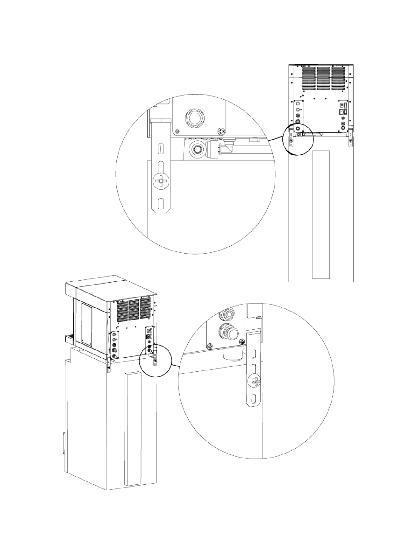
24
NOTE: The DWM-20A cannot be mounted on the cabinet door models (– DS version) of the AM-50/C-80 models
Mounting Brackets for the DWM-20A
and AM-50/C-80
Anchoring the DWM-20A on top AM-
50/C-80 units
25
WARNING: The CO
2
tank must be secured to the wall with a metal chain or restraint (not included, order separately)
FRONT
SIDE
Completed Installation of DWM-20A on AM-50/C-80
26
BACK
BACK CORNER
Completed Installation of DWM-20A on AM-50/C-80
Water
Source
Water
Source
27
MAX 20 lbs
MAX TILT = 15 DEGREES
15° MAX
WARNING: MAX LOAD WEIGHT ON
TOP OF DWM-20A = 20 LBS
WARNING: DO NOT TILT
28
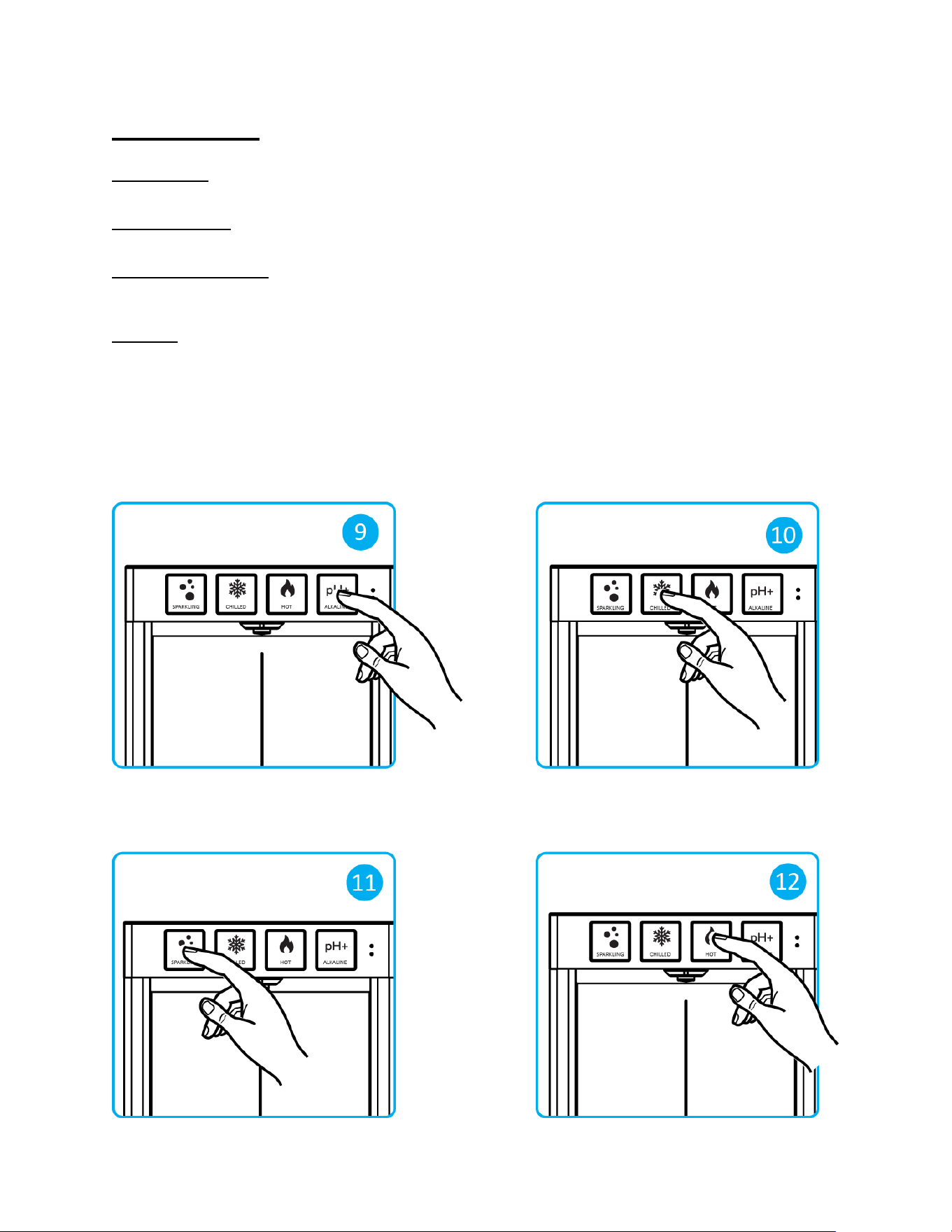
OPERATION
Alkaline Water
Touch and hold the white button to dispense alkaline water (fig 9).
Chilled Still Water
Touch and hold the blue button to dispense chilled water (fig 10).
Chilled Sparkling Water
Touch and hold the green button to dispense chilled sparkling water (fig 11). Increase the bubble level to desired
fizziness level as described in the following page.
Hot Water
Touch and hold red button to dispense hot water (fig 12).
The red LED light indicator labeled “HOT WATER” at the right corner on the touch panel indicates that the DWM-20A
is ready to dispense hot water. If the red light indicator is off, the dispenser will not dispense hot water because the
child safety is inserted (“YES”). To turn on the hot water dispensing function, simply turn off the “Child Safety Switch”
located on the back of the dispenser (move it to its disabled position: up, where the word “NO” is indicated), and be
sure to turn on the red Hot Water switch on the back of the unit as well, in order to switch the hot water tank heater
on.
29
TIP: For precise adjustment of carbonation level, measure the inlet water pressure entering DWM-20A and follow this
table below:
Inlet Water Pressure CO
2
Pressure
45 psi 45-50 psi
50 psi 50-55 psi
55 psi 55 psi
60 psi 60 psi
65 psi 65 psi
30
MAINTENANCE
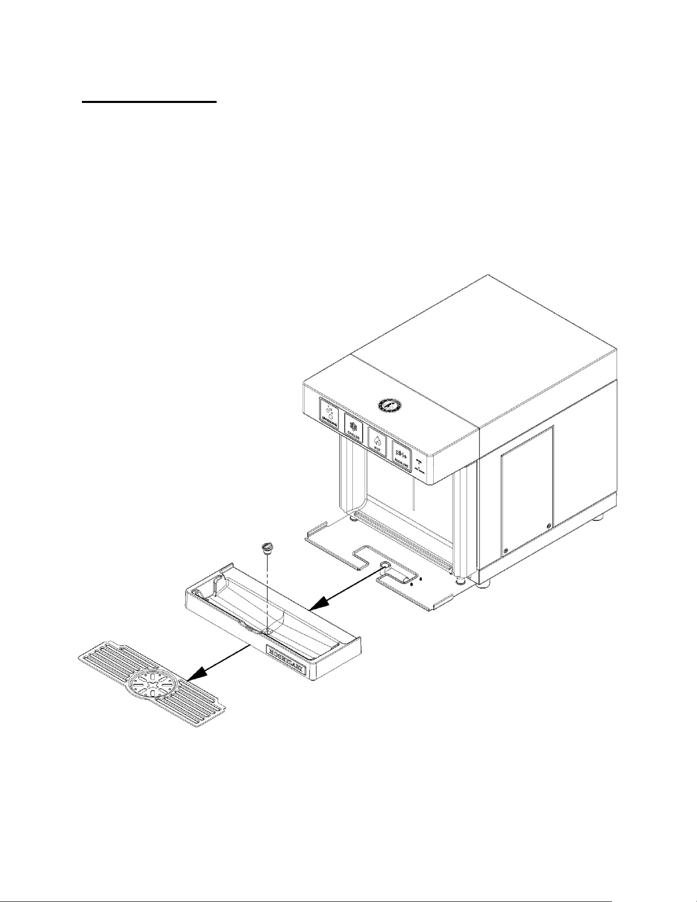
Empty Drain Pan
If the drain pan is NOT connected to its drain line, it must be regularly emptied:
• Gently pull the drain pan with care to avoid spilling.
• Empty the water inside and clean the drain pan with soapy water if necessary.
• Put the drain pan back in place.
Plug
Plastic Drain Pan Bottom
Drain Pan Top

31
CO
2
Tank Replacement
If the arrow on the “Capacity Gauge” is in the red region, it is time to replace the CO
2
tank. Follow these steps below:
1. Fully close the main valve on top of the CO
2
tank.
2. Release gas pressure by touching the green button on the water dispenser and dispensing sparkling water, or by
pulling the gas valve (see fig 6 on page 18).
3. Shut the the CO
2
regulator, turning the knob counter-clockwise until the arrow on the “Gas Pressure Gauge” is
close to zero.
4. Using a wrench, remove the regulator from the empty tank.
5. Screw the CO
2
regulator to the new (full) tank.
6. Open the main valve on top of the tank completely.
7. Open the CO
2
valve (clockwise) on the regulator knob.
8. Reset the gas pressure to the desired level (i.e. the arrow must be in the green region).
Cleaning and Sanitation
WARNING
SANITARY GLOVES ARE TO BE USED DURING CLEANING OPERATIONS. APPLICABLE SAFETY
PRECAUTIONS MUST BE OBSERVED. INSTRUCTION WARNINGS ON THE PRODUCT MUST BE
FOLLOWED.
CLEANING SOLUTIONS CONTAIN ACIDS. THESE COMPOUNDS MAY CAUSE BURNS. IF SWALLOWED, DO
NOT INDUCE VOMITING. CALL PHYSICIAN IMMEDIATELY. IN THE CASE OF EXTERNAL CONTACT, FLUSH
WITH WATER. KEEP OUT OF REACH OF CHILDREN.
The DWM-20A is constructed with high quality stainless steel. Cleaning with a glass cleaner and a soft cotton cloth
will keep the stainless steel of the DWM-20A clean. Using sparkling water to clean external surfaces is also an option.
Surface Finish Care
Do not use cleaners containing chloride, chlorine bleach solutions, concentrated soaps, water with high salinity, or
hydrochloric acid, since they will cause corrosion or discoloration of the stainless-steel surface.
Do not use metal scrapers, sharp objects, steel wool, scouring pads, or abrasives on the unit.
Do not use a water jet to clean the surface.
Highly concentrated cleaners may cause aesthetic damage to plastic and metal finishes.
32
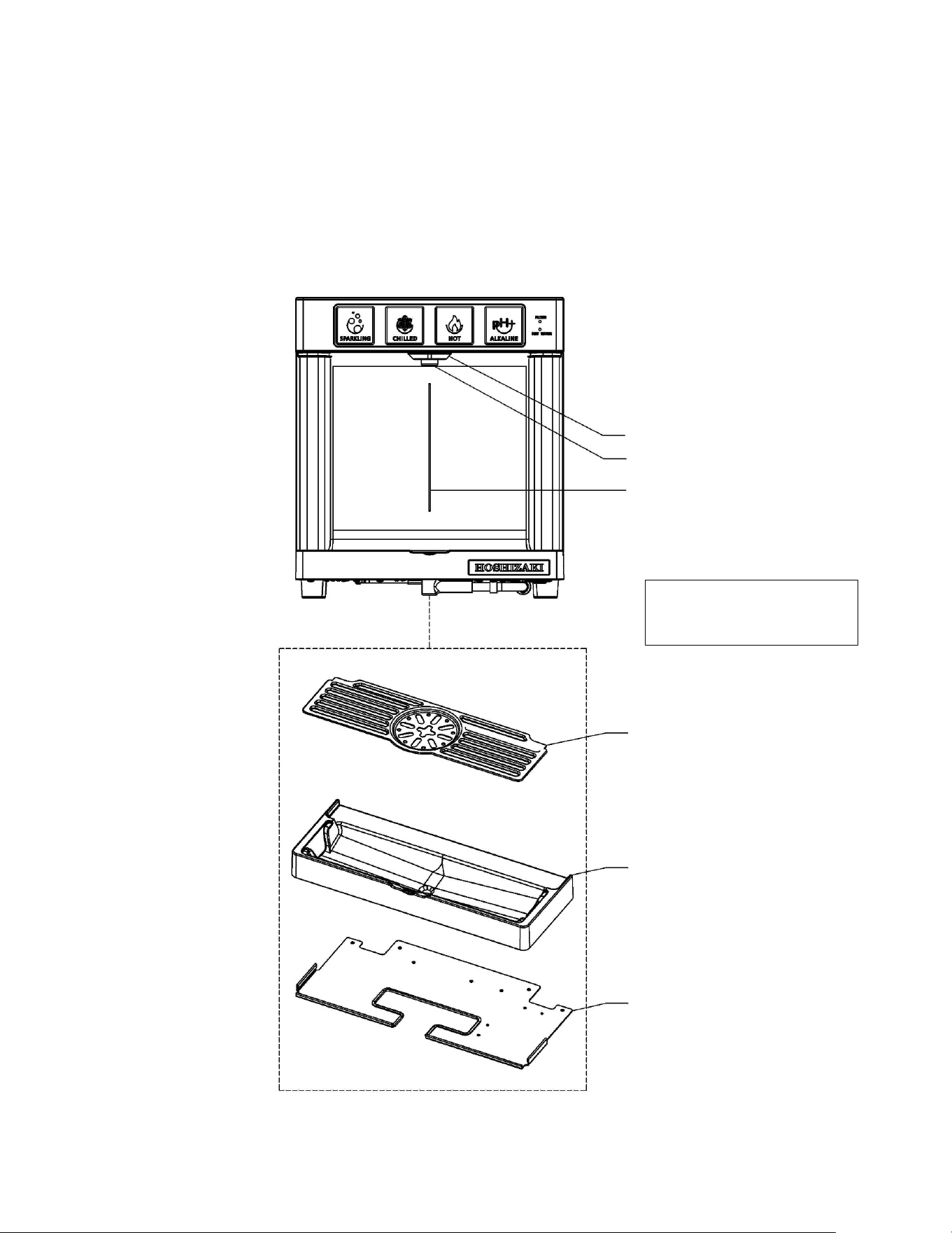
Areas of Maintenance
Routine sanitization of the DWM-20A dispenser should be performed on the following parts:
1) Nozzle
2) Nozzle Guard
3) Front Plate Dispensing Area
4) Drain Pan Top
5) Drain Pan Bottom
1. Nozzle
2. Nozzle Guard
3. Front Plate Dispensing Area
4. Drain Pan Top
5. Plastic Drain Pan Bottom
Drain Pan Plate
Update drawing with new
design of drain pan top
33
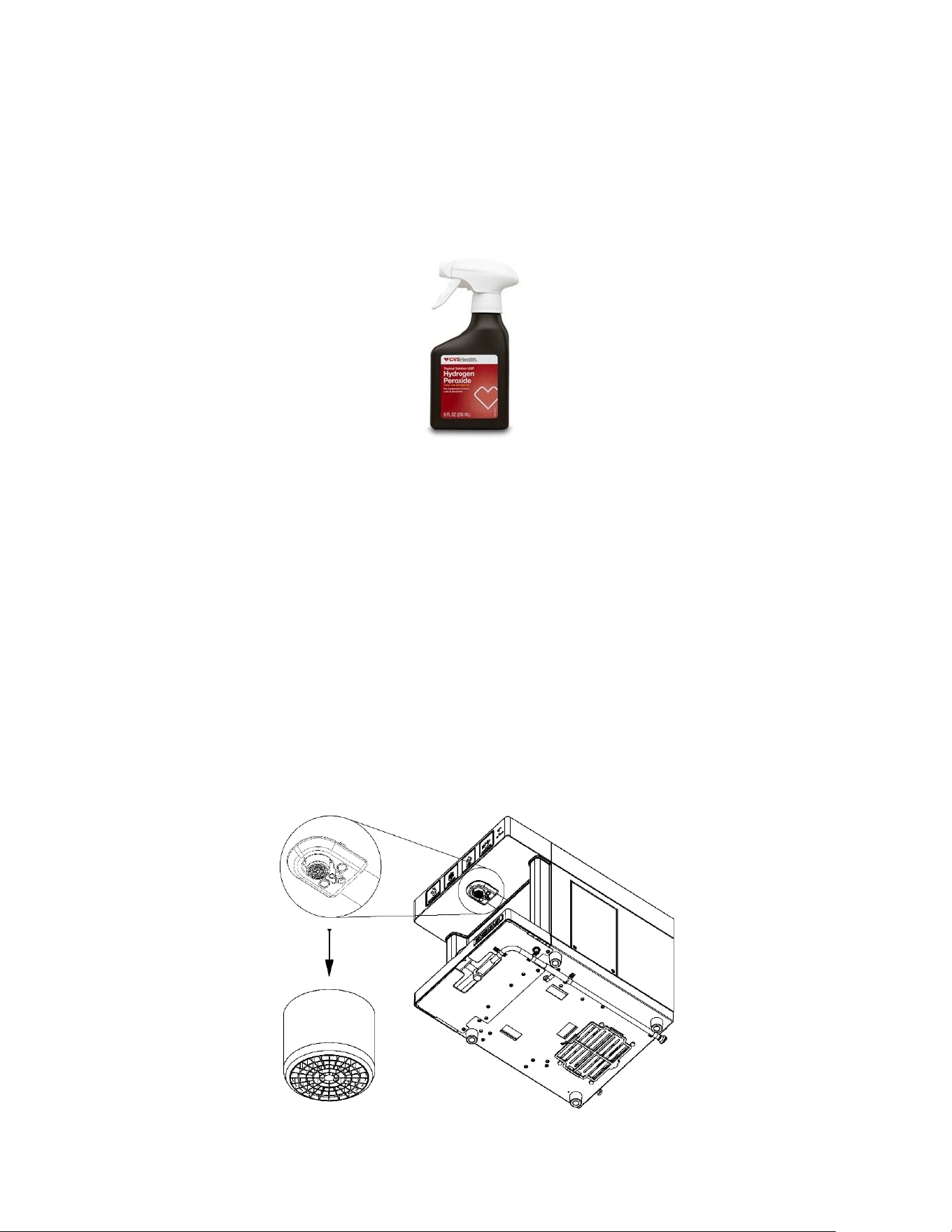
Example: Hydrogen Peroxide (3% Solution) Spray
Daily
Keep exterior surfaces of the dispenser (nozzle, nozzle guard, front plate dispensing area, drain pan top, drain pan
bottom) clean by using a clean, damp cloth. While wearing sanitary gloves, sanitize the exterior surfaces with a
hydrogen peroxide (3% solution) and allow the surface to air dry. When cleaning and sanitizing the touch buttons, be
sure to power off the dispenser to prevent accidentally dispensing water. Additionally, it is important to keep the drain
pan clean of debris. Remove any as soon as it is noticed.
Weekly
Use a vacuum to clean out dust from all the vents.
Pour hot water into the drain pan to keep the drain open (if the drain pan is connected to a drain line).
Every Six Months
NOTICE: These operations must be carried out by an authorized technician and should be done every time the All-in-
One filters and alkaline chamber are replaced.
1) Replacing the Nozzle Tip:
A. Disconnect the power so that water is not accidentally dispensed.
B. While wearing sanitary gloves, remove the nozzle cap by unscrewing it counterclockwise. Remove the
aerator and o-ring from the nozzle cap. A special tool is available from Hoshizaki.
C. Insert new aerator and o-ring (both available as service parts from Hoshizaki) into the nozzle cap and screw
the assembly back into the nozzle.
Nozzle Tip
34
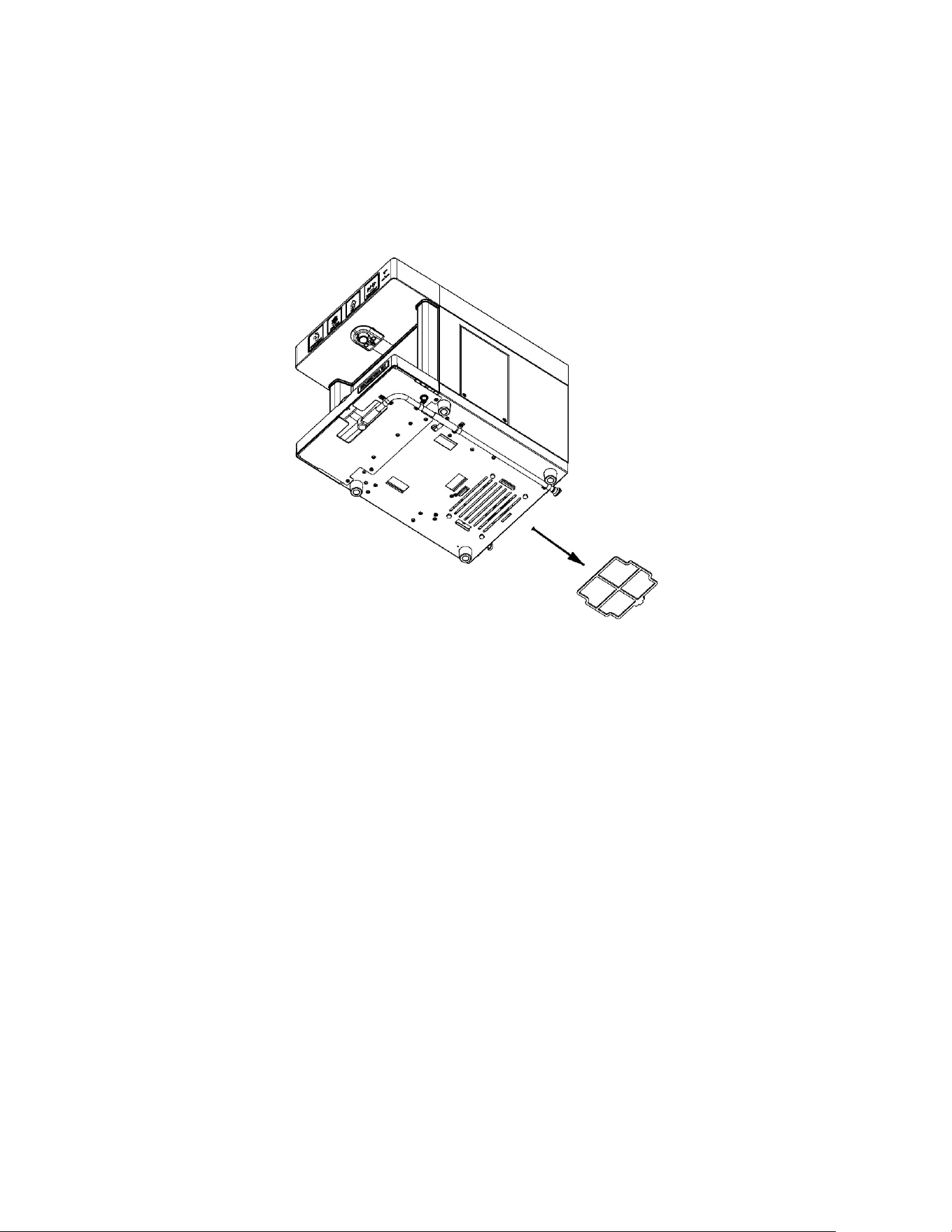
2) Replacing the Air Filter
A. The air filter is located underneath the dispenser. While wearing sanitary gloves, slide the air filter out of the
dispenser.
B. Slide in a new air filter into the dispenser.
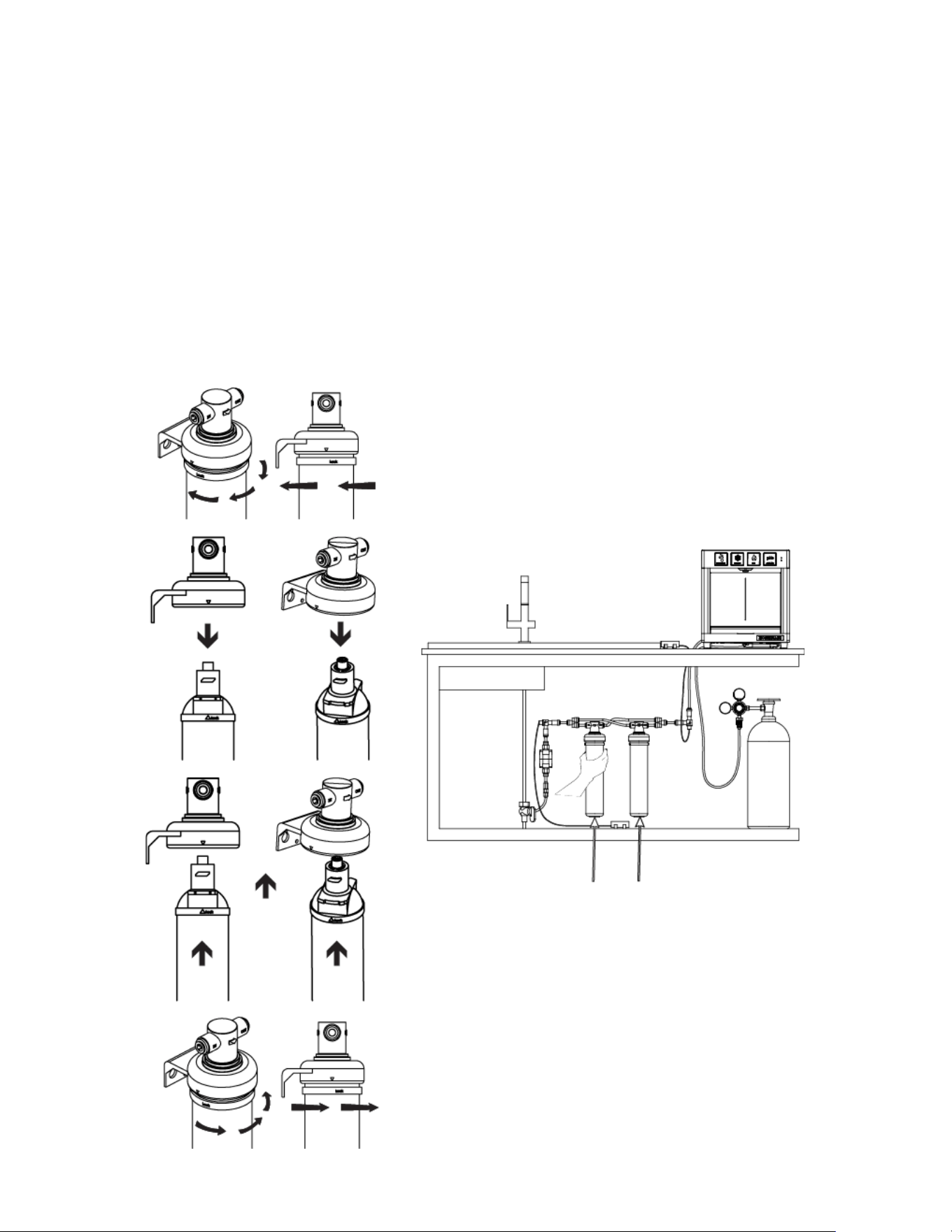
3) Replacing the 2 external All-in-One filters (HS-5441) and the internal alkaline
chamber (HS-5442)
Replace the two external All-in-One filters (HS-5441) and the alkaline chamber (HS-5442) when the filter life green
LED indicator blinks (i.e. it means that 6,000 gallons have been dispensed by the DWM-20A dispenser) or every 6
months, whichever comes first. Instructions are also found on the label of the All-in-One filter (HS-5441) and on the
label of the alkaline chamber (HS-5442). Follow this procedure step-by-step:
A. Locate the main water shutoff valve (the angle stop valve).
B. Shut off the water line valve (i.e. the angle stop valve) and relieve the water line pressure by selectively touching
the dispensing buttons until no more water comes out from the dispenser.
C. Locate the two All-in-One filters HS-5441.
D. Hold the head of each filter firmly. Rotate the cartridge clockwise, ¼ turn, and pull it out.
E. Insert a replacement cartridge by rotating it counter-clockwise, 1/4 turn, until it clicks and stops. The arrow on the
top collar should align with the arrow on the head.
F. Get a bucket or sink to flush filters: remove the water line from the back of the dispenser and re-open the water
supply so that the HS-5441 filters can be flushed out in a 5 gal. bucket or in the sink. Flush the filters for 5
minutes or until the water runs clear. DO NOT flush the filters through the dispenser.
G. When the two new HS-5441 filters have been flushed, shutoff the main water valve (angle stop valve) again and
locate the alkaline chamber HS-5442 inside the side panel door on the right side of the dispenser.
H. Unscrew and remove the panel to reveal the alkaline chamber.
Air Filter
35
I. Rotate the alkaline chamber clockwise, 1/4 turn, and pull it out.
J. Insert a new alkaline chamber by rotating it counter-clockwise, 1/4 turn, until it clicks and stops. The arrow head
on the top collar should align with the arrow on the head.
K. Re-insert the water line into the “WATER IN” port on the back of the dispenser and re-open the main water line
valve.
L. Now flush the alkaline chamber by dispensing approximately 2 gallons of alkaline water using the alkaline touch
button. When the alkaline water comes out clear, the dispenser is ready.
M. At this point, before closing the side panel door, it is wise to check for leaks from the All-in-One filters HS-5441
and the alkaline chamber HS-5442. Make sure they are sealed correctly. Push the filter reset (”FR”) button at the
back of the dispenser for 10 seconds in order to reset the volumetric count of water consumption.
Replace the two HS-5441 Filters
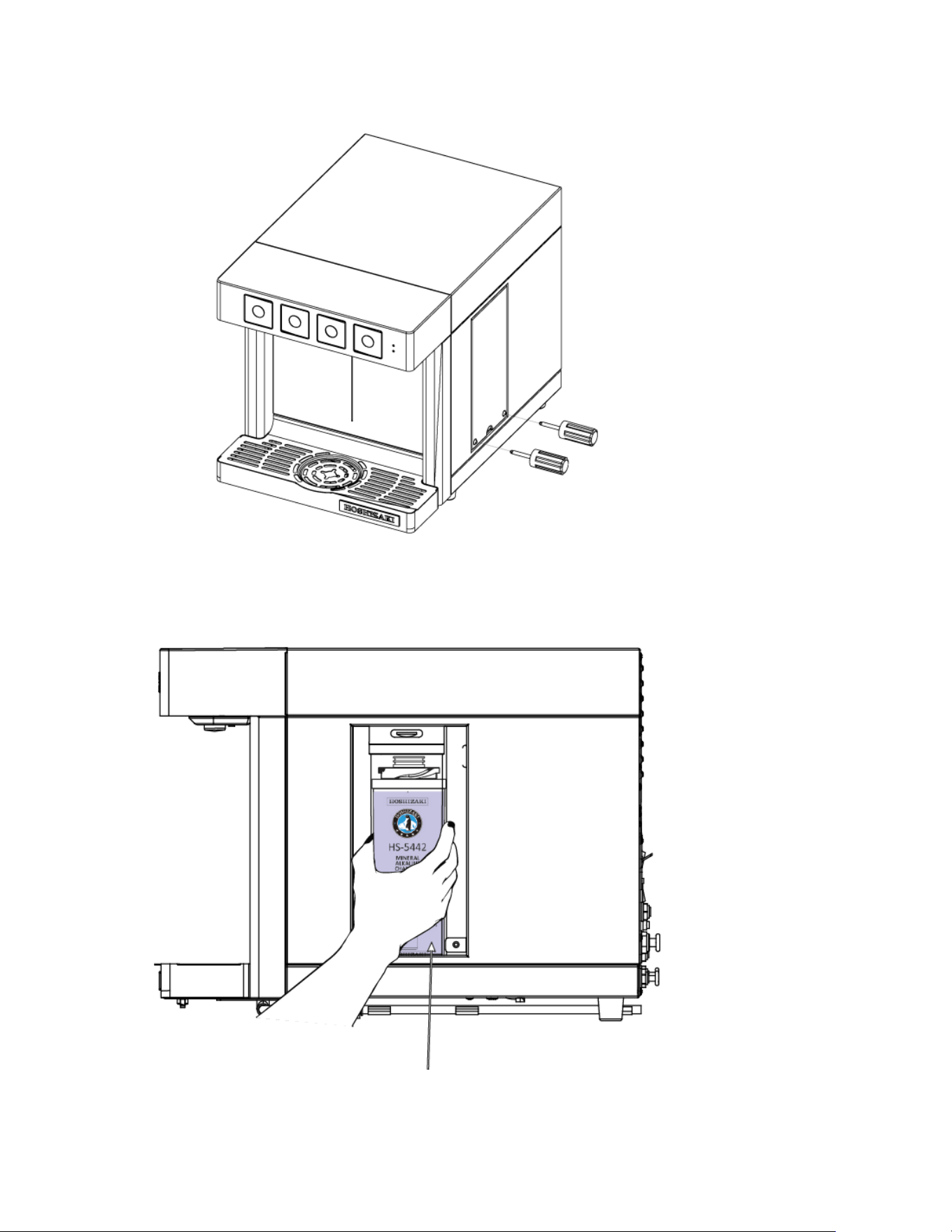
36
Open the Side Panel Door
Replace the alkaline chamber HS-5442
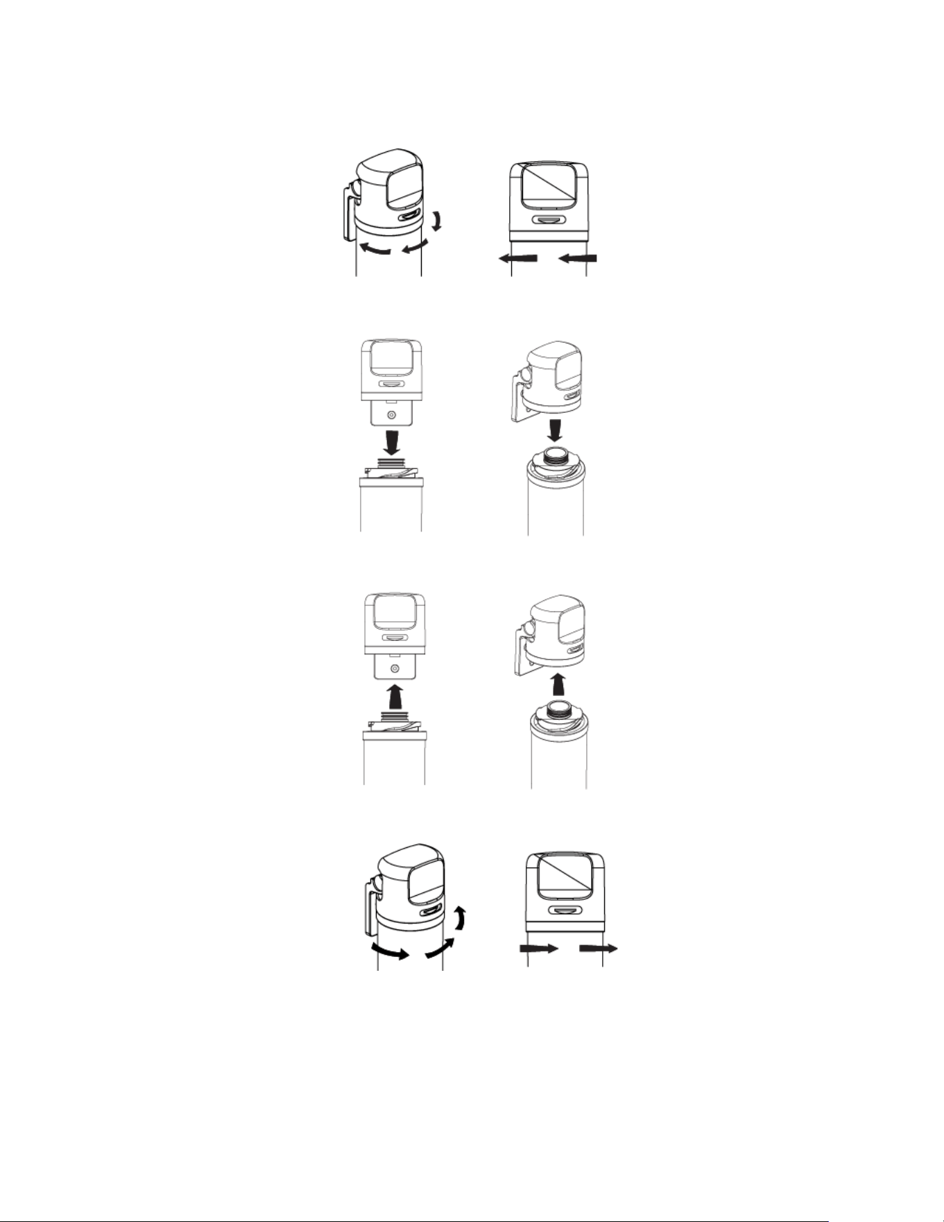
37
Changing the Alkaline Chamber
1. Shut off water and relieve line pressure.
2. Hold head firmly. Rotate the old cartridge clockwise 1/4 turn and pull it out.
3. Pull cartridge down and out of the head.
4. Hold head firmly. Insert new cartridge into the filter head.
5. Turn the new cartridge into the filter head and rotate counter-clockwise 1/4 until rotation clicks and stops.
6. Flush filter for 5 minutes before use or until water runs clear, by touching the (white) Alkaline button.
38
4) Cleaning and Sanitizing the Hot Water Tank
NOTICE: This operation must be carried out by an authorized technician. This operation takes one hour.
You must follow the guidelines and procedures for the cleaning and sanitizing solution established by the
manufacturer.
WARNING
WATER TO DRAIN MAY BE EXTREMELY HOT (190°F). Do not turn off the hot water switch on the
back of the dispenser. Before starting, confirm that the water line is properly connected.
1. Empty the hot water tank by using the drain line.
2. Prepare and add 950 ml of cleaning solution from the drain line into the hot water tank by using the hot water
tank inflow system (order separately). To check if the hot water tank is full of solution, dispense hot water until
you see solution coming out of the nozzle.
3. Leave the cleaning solution inside for 5 minutes.
4. Press the hot water button and dispense at least 2 gallons.
5. Empty all the liquid from the hot water tank by using the drain line.
6. Prepare the sanitizing solution (order separately). Dilute the sanitizing solution with water at 10-15%. Use the
same hot water tank inflow system to fill the hot tank.
7. Leave the sanitizing solution inside the Hot Water Tank for 20 to 30 minutes.
8. Begin dispensing liquid from the hot water line. You must dispense at least 2 gallons.
9. Repeat step 6, 7 and 8 above for a second time.
10. Empty all the sanitizing solution from the hot water tank by using the drain line.
11. Begin dispensing water from the hot water line. This will fill the Hot water Tank with water. Empty the hot tank
from the drain line and repeat this process twice to ensure that all the sanitizing solution is out.

39
Electrical System
The DWM-20A dispenser must be plugged directly into 110/120 VAC, 60Hz wall outlet only (15 Amps). A 15A –
125VAC / 250VAC circuit breaker is installed on the dispenser and the circuit breaker can be accessed for reset at
the back of the dispenser (i.e. Power Reset Button).
IMPORTANT: In case of breaker trip, only reset once. If it happens again shortly after, send the water dispenser back
to the Manufacturer for maintenance.

40
Transporting and Relocating
If the DWM-20A dispenser needs to be relocated to another place or sent back to the manufacturer or the dealer for
repairs, it is necessary that the water inside the hot water tank and the refrigeration system is drained. Please follow
the below procedures:
1. Close the CO2 supply line by turning the handle knob (turn clockwise) on the CO2 tank’s regulator.
2. Dispense sparkling water (green button) to make sure that sparkling water comes out totally flat (no gas).
3. Close the water supply line and turn the shut-off valve located right behind the dispenser to the “off” position.
4. Dispense alkaline water (white button) until no more water is dispensed from the dispenser.
NOTE: DO NOT dispense chilled water (blue button).
5. Turn the Main Power switch to its “off” position. The main power switch is located on the back of the dispenser.
Leave the dispenser disconnected for 24 hours to defrost its refrigeration system.
6. After 24h or more, proceed with de-installation. Unplug the power cord from the back of the dispenser.
7. Unplug the CO2 tube (1/4” tube) on the back of the dispenser.
8. Unplug the “WATER INLET” tube (3/8” tube) on the back of the dispenser.
9. Locate the “Cold Drain” and “Hot Drain” on the back of the dispenser. Remove the plug from the “Cold Drain” to
drain the water from the dispenser’s refrigeration system and drain into a bucket or container. These will be
about 2 gallons of water. IMPORTANT: Use a five-gallon minimum container to collect the water drained from
the dispenser.
10. Next, repeat the process for “Hot Drain”. WARNING: Water from “Hot Drain” may still be hot, even after 24
hours.
11. Put the plugs back into the “Cold Drain” and “Hot Drain”. The DWM-20A dispenser is now ready to be
transported. Package the dispenser carefully, as its stainless steel external surfaces might be easily damaged
during transportation.
12. In case of swap-out between two DWM-20A, remember to also change both the filters (HS-5441), and the
alkaline chamber (HS-5442).
For help during de-installation, call our toll-free service number at 1 (800) 233-1940.
41
TECHNICAL SUPPORT
Troubleshooting
A. Lights are off
Check that the dispenser is NOT in its “SLEEP MODE”.
If the green dot light indicator (top right of the front
plate) is illuminated, the dispenser is simply “sleeping”.
Touch any button for a few seconds to start it and all
buttons will illuminate. If ALL lights are off (including
the two LED indicators at the top right of the touch
panel), check the main power cord connection: if
plugged in, check main power switch. If the dispenser is
connected to a power source, and if the main power
switch is on, press the power reset button once or
twice. The power reset button is located at the back of
the dispenser, just below the main power switch and is
indicated with the letters “PR” (i.e. Power Reset).
B. Both the green & red LED indicators are blinking,
while all four (4) touch buttons are off and no water can
be dispensed
The DWM-20A has entered “SAFETY MODE”. There
is no water in the supply tubing or the water pressure is
too low. Or somebody has operated the unit
dispensing more than 1.5 liters without pausing, or for
more than 30 seconds without pausing. If the issue is
no water, make sure water supply valve is open or, to
address low water pressure, replace filters or use
booster pump to increase water pressure. Once the
issue is solved, turn off the unit and after three seconds
turn it on again. If the issue is solved, the unit will
restart normally.
If it persists call 1 (800) 233-1940 for help.
C. There is an audible beeping sound
A leak detector is activated. In that case, proceed as
per instructions (see page 43) and reset the leak
detector to work.
D. Sparkling & Alkaline touch buttons are blinking
Indicates that the refrigeration system must be filled up.
Touch and hold both buttons contemporarily for three
seconds until ALL the buttons are blinking. Wait until all
buttons stop blinking and are solid. Now the dispenser
should be able to operate. Make sure there is water in
your pipeline flowing to the dispenser. If not, check your
water line; perhaps you need to open the shutoff valve
located at the back of the dispenser or the main shutoff
valve at your location.
E. All four (4) touch button lights are blinking
Indicates that the refrigeration system is being filled
with water. You should be able to hear it. If not, check
the water line; perhaps you need to open the shutoff
valve located at the back of the dispenser or the main
water valve at your location. If there is water in your
pipeline this operation lasts five (5) to ten (10) minutes.

42
F. Does not dispense hot water at all
“Child Safety Switch” is on its “YES” position (i.e.
down), indicating that child safety switch has been
enabled. To allow hot water to be dispensed, turn the
“Child Safety Switch” at the back of DWM-20A to its
“NO” position (turn it up). The red LED dot indicator on
the touch panel of DWM-20A should turn on.
G. Hot water is not hot
Check if the hot water power is on (red switch on the
back). If not on, turn it on (up) and wait ten (10)
minutes for the water to reach its maximum
temperature.
H. Hot water touch button (red) is off. All other buttons
are on.
The DWM-20A entered “ENERGY SAVING” and
automatically disconnected the hot water tank because
it was not used for an entire month. Push and hold the
hot water button (red) for 15 seconds: the button’s red
light will be on again and hot water will start coming out.
I. Does not dispense water at all, even when pushing
the Alkaline option (white button)
There is no water in your pipeline, Check the main
water supply connection and all the shutoff valves.
J. Sparkling water comes out flat, or no carbonated
enough
Check the CO2 tank: the “Capacity Gage” might be in
the red region. If it is in the red region, replace tank.
Otherwise, if the tank is full, adjust pressure to
necessary levels using CO2 regulator: arrow must be in
between 50 and 65 psi. If gas pressure is high while
water is dispensed totally flat, turn the knob on the gas
regulator anticlockwise (i.e. close it). Then release
pressure by cutting the gas tube (see fig 6 on page 18).
K. Green light indicator is blinking
The DWM-20A dispenser requires 2 new filters and a
new alkaline chamber. Call 1 (800) 233-1940. After
replacing the filters and the alkaline chamber, push and
hold for 5 seconds the Filter Reset button (indicated
with the words “FR”) at the back of the DWM-20A, until
the green LED indicator turns solid green back again.
L. None of the above
Switch the dispenser off (main power switch), as per
Maintenance section of this Manual, page 42) and
contact customer service for assistance. 1 (800) 233-
1940.
43
Leak Detector Troubleshooting
The installation kit for DWM-20A provides one (1) leak detector which will automatically shut off the water to the
dispenser if leaks are detected (assuming that its electrodes are correctly positioned and its alkaline battery is
charged).
However, very often leak detectors are activated by minor water spillage from the drain pan and/or a partially wet
counter. In that case a beep is clearly audible and the leak detector must be reset.
See the table below for leak detector troubleshooting and instructions.
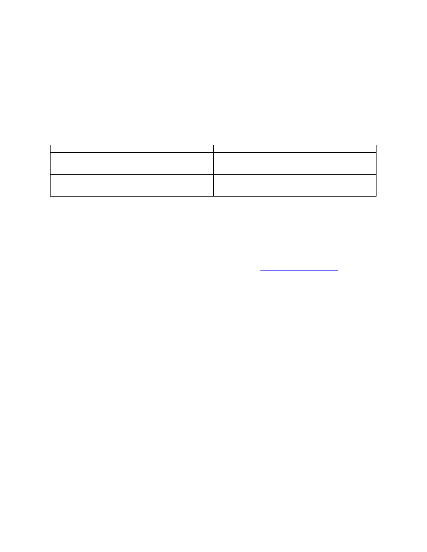
Problem
Action
Blue light continuously blinking & continuous audible
beeping.
After the leakage problem is solved, press the light blue
button for 5 seconds. The detector will emit a long
beeping sound, then will resume operation.
Red light continuously blinking & continuous audible
beeping.
Replace battery. To do so, remove the battery cover on
the right side of the control unit and replace the 9V
battery.
Support
For any questions, please contact customer service for assistance at the toll-free number 1 (800) 233-1940.
Recycling Program
Return the used DWM-20A to the manufacturer, whose address is listed on www.hoshizakiamerica.com
Please visit our website
www.hoshizakiamerica.com
Or call our toll-free number at 1 (800) 233-1940

44
WARRANTY CONDITIONS
Three-Year Limited Warranty for DWM-20A dispenser to consumers. This Limited Warranty is only valid for the
United States of America and its territories. For installations outside of the USA call 1 (800) 233-1940 to receive
related Warranty.
The manufacturer warrants this dispenser against defects in material or workmanship for a period of three years, if
this dispenser is purchased either directly from the manufacturer or from its authorized retailers or distributors. Under
this Limited Warranty, the manufacturer will either, (i) repair the dispenser using new or refurbished parts or, (ii)
replace this dispenser with a new or refurbished dispenser with the same or superior specifications or performance
characteristics. For the purpose of this Limited Warranty, a “refurbished” dispenser or part is one that has been
returned to its original specifications. In the event of a defect, the above is your exclusive remedy and the
manufacturer’s only liability.
LIMITATIONS OF WARRANTY
This Limited Warranty covers ONLY the dispenser. It DOES NOT cover its external filtration system, alkaline
chamber, the CO2 tank used in connection with the dispenser, the CO2 regulator which is fixed to the tank, the parts
constituting the “Installation Kit” as per the Instruction Manual, or any other consumables, accessories or components
that might be packaged together with the DWM-20A dispenser. It DOES NOT cover software updates or
modifications, whether or not contained in the box. No remedy is available under this warranty if you do not use
DWM-20A original filtration system. You will have no remedy under this Limited Warranty in the event of any
tampering with this dispenser. Connecting this unit with water sources or electrical power supply with characteristics
or specifications other than those described in the Instruction Manual will automatically deprive you of any remedy
under this Limited Warranty. Not using original parts, including HS-5441 filters and HS-5442 alkaline chamber, not
replacing the cartridges (both HS-5441 and HS-5442) every six months or when filter life LED indicator starts blinking,
whichever comes first, flushing external filters through this dispenser or using the dispenser in a way that is not
intended voids this Warranty. This Warranty DOES NOT cover normal wear-and-tear to the dispenser or its
components, or any damage due to negligent or improper use of the dispenser (please refer to the Manual). The
Warranty is also void for damages or malfunctioning due to sub-standard installation of the dispenser performed by
persons, other than authorized technicians. This Limited Warranty DOES NOT cover a dispenser sold AS IS and it
DOES NOT cover technical assistance for the installation/usage of the dispenser on ships, boats or other means of
transport.
OTHER LIMITATIONS
This Limited Warranty only covers issues and malfunctions caused by defects in material or workmanship during
ordinary and recommended/allowed use of this dispenser (see Manual). It does not cover issues caused by any other
reason, including but not limited to acts of God, misuse (including, but not limited to, using this dispenser outside the
specs indicated in the Instruction Manual), limitations of technology, or modification of or to any part of this dispenser.
It does not cover any dispenser purchased from anyone other than the manufacturer or its authorized retailers or
distributors. To determine if a retailer or distributor is authorized, please visit www.hoshizakiamerica.com
or contact
the Manufacturer’s customer service line. You will have no remedy under this Limited Warranty if the factory applied
serial number has been altered or removed from the back of this dispenser or if the Manufacturer’s original warranty
stickers on the back of the dispenser have been removed or cut and are not replaced. This Limited Warranty is not
valid outside of the U.S.A. and its territories.

45
INSTRUCTIONS
To obtain warranty service, you must deliver this dispenser, freight prepaid, in either its original box, or packaged
affording an equal degree of protection to the manufacturer: Hoshizaki America, Inc. at the address specified on the
manufacturer’s website www.hoshizakiamerica.com
and available by contacting the manufacturer at
1 (800) 233-1940. A dated purchase receipt from the manufacturer or its authorized retailer or distributor is also
required.
WARRANTY ON REPAIR/REPLACEMENT
This Limited Warranty shall apply to any repair, replacement part or replacement dispenser only for the remainder of
the term of the Limited Warranty on the original dispenser, or ninety (90) days from the customer’s receipt of the
repaired/replacement part or dispenser, whichever is longer. Any parts or dispenser replaced under this Limited
Warranty will become property of the manufacturer.
WARNING
DO NOT REMOVE THE COVER OR THE BACK OF THIS DISPENSER: THERE ARE NO SERVICEABLE PARTS
INSIDE! DOING SO MIGHT RESULT IN ELECTRIC SHOCK OR OTHER INJURIES AND WILL AUTOMATICALLY
DEPRIVE YOU OF ANY REMEDY UNDER THIS WARRANTY.
WARRANTY DISCLAIMER
THIS WARRANTY IS IN LIEU OF ANY OTHER IMPLIED OR EXPRESS WARRANTIES.
LIMITATION OF LIABILITY
THE MANUFACTURER SHALL UNDER NO CIRCUMSTANCES BE LIABLE FOR ANY INCIDENTAL OR
CONSEQUENTIAL DAMAGES, WHETHER FOR BREACH OF WARRANTY OR OTHER CONTRACT BREACH,
NEGLIGENCE OR OTHER TORT, OR ON ANY STRICT LIABILITY THEORY. Some states do not allow the
exclusion or limitation of incidental or consequential damages, so the above exclusion may not apply to you. This
warranty gives you specific legal rights, and you may also have other rights which vary from state to state.