FREE STANDING OVEN
90x60 Gas & Electrical Oven
USER MANUAL
GB
ES
H10-20-180-088 Rev 003
GUIA DEL USUARIO

2
Dear User,
Our objective is to make this product provide you with the best
output which is manufactured in our modern facilities in a careful
working environment, in compliance with total quality concept.
Therefore, we suggest you to read the user manual carefully before
using the product and, keep it permanently at your disposal.
Note: This user manual is prepared for more than one model. Some
of the features specied in the Manual may not be available in your
appliance.
All our appliances are only for domestic use, not for commercial use.
* Mark the products as option.
“THIS APPLIANCE SHALL BE INSTALLED IN ACCORDANCE WITH THE
REGULA TIONS FORCE AND ONLY USED IN A WELL VENTILATED SPACE. READ
THE INSTRUCTIONS BEFORE INSTALLING OR USING THIS APPLIANCE”
“Conforms with the WEEE Regulations."
GB

3
CONTENTS
Important Warnings
4
Introduction Of The Appliance 7
Important Warnings 8
Electrical Wiring Scheme 9
Gas Hose Passage Way 10
Chain Lashing Illustration 11
Installation Of Your Oven 11
Technical Features Of Your Oven 12
Reduced Gas Flow Rate Setting For Hob Taps 12
Reduced Flame Gas Cock Adjustment 13
Description Of Oven 13
Description Of The Control Panels 14
Using The Burner Groups 15
Using Hot Plates 16
Installation Of The Oven Feet 16
Using Oven Section 17
Cooking Time Table 18
Using The Grill Deector Sheet 19
Catalytic Walls 20
Chicken Roasting 20
Cleaning And Maintenance Of The
Oven’s Front Door Glass 21
Changing The Oven Lamp 21
Maintenance And Cleaning 22
Installation Of The Oven Door 23
Accesories 24
Removal Of The Lower And Upper Burner And
Installation Of The Injector To The Gas Oven 25
Injector, Gas Flow And Power Table 26
If Your Oven Does Not Operate
28
Environmentally-Friendly Disposal and
Package Information 28
GB

4
IMPORTANT WARNINGS
1.WARNING: To avoid electrocution, ensure that the
electrical circuit of the product is open before replacing
the lamp.
2.WARNING:Before touching the connection terminals,
all supply circuit should be disconnected.
3.WARNING:While operating the grill, the reachable
sections can be hot. Keep the children away.
4.WARNING:Any inadvertent cooking made with fats and
oils can be dangerous and cause re.
5.WARNING:Risk of re; do not store the food materials
on the cooking surface.
6.WARNING:If the surface is cracked, unplug the device
to prevent any risk of electric shock.
7.WARNING:During usage the reachable sections can be
hot. Keep the small children away.
8.WARNING:The appliance and its reachable sections
become hot during usage.
9.The setting conditions of this appliance is indicated
on the label. (Or data tag)
10.This appliance is not connected to a combustion
product discharge system.This appliance shall be
connected and installed as per the applicable
installation legislation. Consider the requirements
related with ventilation.
GB

5
11.Using a gas hob will release humidity and combus-
tion products in the room where it resides. Especially
during when the appliance in use, ensure that the kitch-
en is well ventilated and retain the natural ventilation
holes or install a mechanical ventilation system. (Hood
on top of the oven) Sustained usage of the appliance
may require additional ventilation. For example open-
ing a window or if available, increasing the ventilation
level of a mechanical ventilation system.
12.The reachable sections can become hot when the
grill is used. Keep the small children away.
13.WARNING:The appliance is intended for cooking only.
It must not be used for other purposes like room heating.
14.There are additional protective equipment to
prevent inadvertent touching to the oven doors. This
equipment should be installed if there are children.
15.“This appliance should be installed as per
regulations and in well-ventilated location only. Read
the instructions before installing or operating the
appliance.”
16.“Before placing the appliance check the local
conditions (gas type and gas pressure) and ensure
that the settings of the appliance is appropriate.”
17.“These instructions are applicable for countries of
which symbols are indicated on the appliance. If the
country symbol is not available on the appliance,in
order to adapt the appliance to the conditions of such
country, the technical instructions should be read.”
GB

6
18.“Do not operate the system for more that 15
seconds. If the burner does not ignite at the end of
15 seconds stop the operation of the system and open
the section door and/or wait for at least 1 minute
before igniting the burner.
19.Do not use steam cleaners to clean the appliance.
20.Before opening the oven door clean the remnants
on it. Before closing the oven door, let it cool.
21.NEVER try to extinguish a re with water, rst
disconnect the mains supply and then using, for
example a lid or blanket, cover the re.
22.Do not use hard and abrasive cleaning agents or
hard metal scrapers to clean the oven door glass as
they may scratch and shatter the surface.
23.After placing a dish, ensure that the door is rmly
closed.
24.Unless continuous supervision is provided, the
children of age 8 or below should be kept away.
25.Pay attention for not to touch the heating elements.
26.This appliance can be used by children aged from
8 years and above and persons with reduced physical,
sensory or mental capabilities or lack of experience
and knowledge if they have been given supervision or
instruction concerning use of the appliance in a safe
way and understand the hazards involved.
GB

7
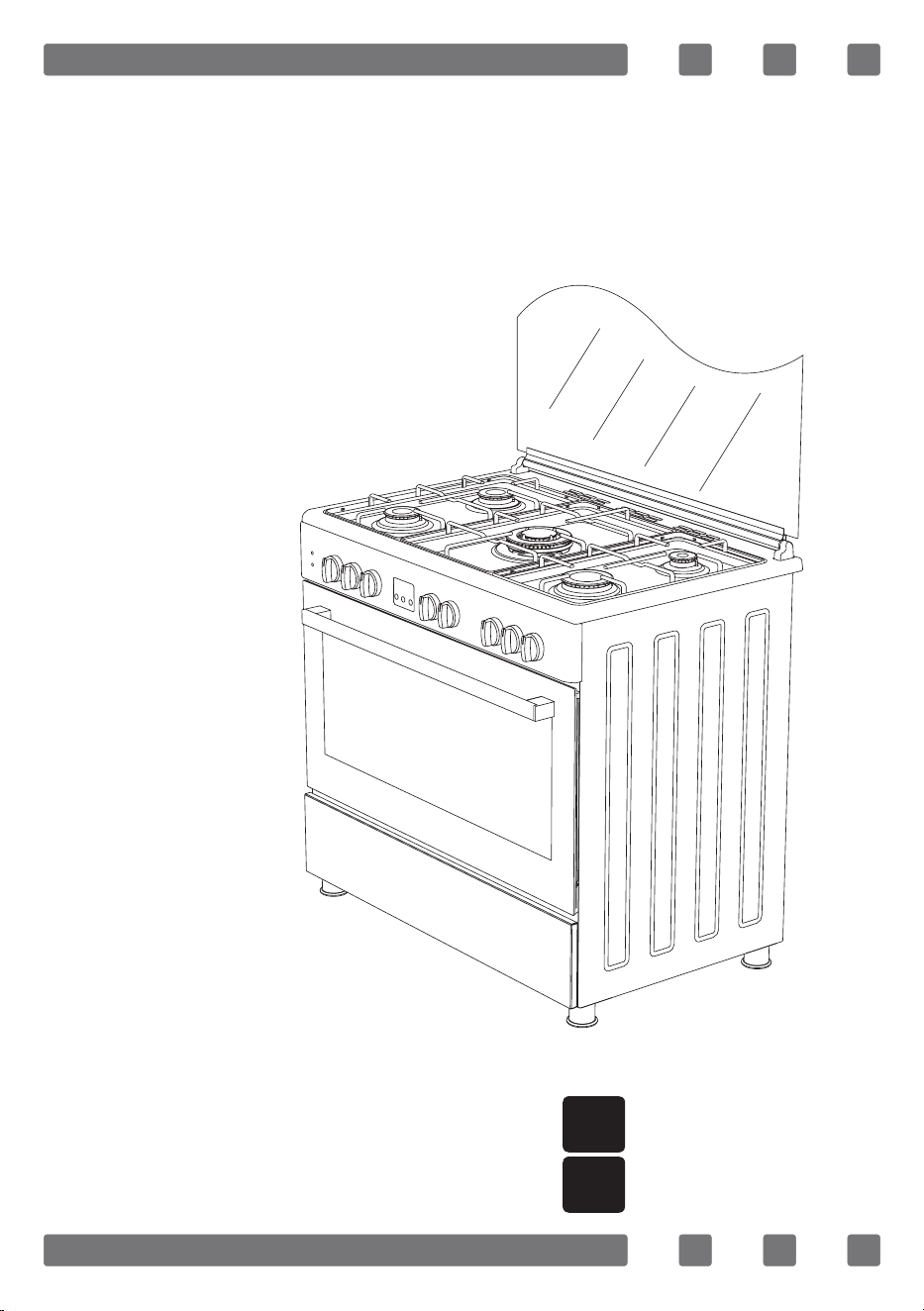
INTRODUCTION OF THE APPLIANCE
21
22
23
24
1
3 4 5 6
2
7*
8*
10
9
11
18
12
13
14
15
16
19
20
17
1. Middle Burner
2. Middle Burner
3. Trivet
4. WOK Burner
5. Large Burner
6. Auxiliary Burner
7. Hot Plate
8. WOK Burner
17. Door
18. Handle
19. Lower Cabinet Door
20. Plastic Leg
21. Lamp
22. Grill
23. Chicken Roasting
24. Deep Tray
9. Glass Door
10. Control Panel
11. Led Lamp
12. Oven Control Knobs
13. Digital Timer
14. Hob Control Knobs
15. Wire Grill
16. Deep Tray
GB

8
IMPORTANT WARNINGS
Electrical Connection and Security
1. Your oven requires 16 or 32 Ampere fuse according to the appliance’s
power. If necessary, installation by a qualied electrician is recommended.
2.Your oven is adjusted in compliance with 220-240V AC/380-415V
AC 50/60Hz.electric supply. If the mains are different from this specied
value, contact your authorized service.
3. Electrical connection of the oven should only be made by the sockets
with earth system installed in compliance with the regulations. If there
is no proper socket with earth system in the place where the oven will be
installed, immediately contact a qualied electrician. Manufacturer shall
never be responsible from the damages that will arise because of the
sockets connected to the appliance with no earth system.
4. Electrical cable should not touch the hot parts of the appliance.
5. For disconnection from the supply mains having a contact separation
in all poles that provide full disconnection, must be incorporated in xed
wiring in according with the wiring rules.
Gas Connection and Security
1. Before your appliance is connected to the gas supply, ensure that
the gas category and pressure specications shown in the data plate cor-
responds with your gas supply. If necessary call authorized service for
adjusting to gas category.
2. This appliance shall be installed in accordance with the regulations
in force and only used in a well ventilated space. Read the instructions
before installing or using this appliance. In the interest of safety this
appliances must be installed and / or serviced by a competent person as
stated in the gas safety regulations current editions.
3. The appliance must not be installed in a room without a window or
other controllable opening. If is installed in a room without a door which
opens directly to the outside, a permanent opening is required. The air
circulation should be 2 m3/h per kW of burners.
4. The gas connection should be performed from the right or left. For
this reason, change the hose nozzle, plug and the seals.
5. Please use exible hose for gas connection.
GB

9
6. If you make a connection with a exible metal hose, locate a seal
between the main gas pipes.
7. The inner diameter of the exible hose, which the butane hose
nozzle is connected, should be 6mm for the house-type gas tubes. The
inner diameter of the exible hose, which the natural hose nozzle is
connected, should be 15mm.The hose should tightly be tted to the
hose nozzle by squeezing with a clamp. The hose should be replaced
before its last expiry date.
8. Caution! Make the oven connection to the gas inlet valve, the hose
length must be short and be sure that there is no leakage. The exible
hose used should not be longer than 125 cm for safety.
9. Re-inspect the gas connection.
10. When placing your oven to its location, ensure that it is at the
counter level. Bring it to the counter level by adjusting the feet if
necessary.
DO NOT MAKE GAS HOSE and ELECTRICAL CABLE OF YOUR OVEN GO
THROUGH THE HEATED AREAS, ESPECIALLY THROUGH THE REAR SIDE OF
THE OVEN. DO NOT MOVE GAS CONNECTED OVEN. SINCE THE FORCING
SHALL LOOSEN THE HOSE, GAS LEAKAGE MAY OCCUR.
ELECTRICAL WIRING SCHEME
220-240V~50/60Hz 220-240V~50/60Hz
400V 3N~50/60Hz 400V 2N~50/60Hz
Earth
Terre
Erdung
Earth
Terre
Erdung
Earth
Terre
Erdung
Earth
Terre
Erdung
L3
L2
L1
L2
L1
L1
Live
Phase
Neutral
Neutre
Neutral
Neutre
Neutral
Neutre
H05 VV-F 3G 4mm² H05 VV-F 5G 1.5mm² H05 VV-F 4G 1.5mm² H05 VV-F 3G 1.5mm²
Neutral
Neutre
380-415V 3N~50/60Hz 380-415V 2N~50/60Hz
220-240V~50/60Hz 220-240V~50/60Hz
GB
10
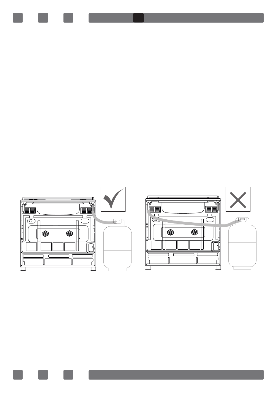
GAS HOSE PASSAGE WAY
1. Connect the appliance to the gas piping tap in shortest possible route
and in a way that ensure no gas leakage will occur.
2. In order to carry on a tightness and sealing safety check ensure that
the knobs on the control panel are closed and the gas cylindir is open.
3. While performing a gas leakage check, never use any kind of lighter,
match, cigarette or similar burning substance.
4. Apply soap bubble on the connection points. If there is any kind of
leakage then it will cause bubbling.
5. While inserting the appliance in place ensure that it is on the same
level with the worktop. If required adjust the legs inorder the make level
with the worktop.
6. Use the appliance on a level surface and in a well ventilated
environment.
Figure 1 Figure 2
GB

11
CHAIN LASHING ILLUSTRATION
Before using the appliance, in
order to ensure safe use, be sure
to x the appliance to the wall
using thechain and hooked screw
supplied. Ensure that the hook is
screwed into the wall securely.
INSTALLATION OF YOUR OVEN
650mm min.
850 mm min.
900 mm min.20 mm 20 mm
GB

12
TECHNICAL FEATURES OF YOUR OVEN
SPECIFICATIONS 90x60
Outer Width 900mm
Outer Depth 610mm
Outer Height 925mm
Lamp Power 15W
Bottom Heating Element 2000W
Top Heating Element 1500W
Grill Heating Element 2500W
Turbo Heating Element 1250W x 2
Supply Voltage 220-240V AC/380-415V AC 50/60Hz
Hotplate 145mm* 1000W
Hotplate 180mm* 1500W
Hotplate Rapid 145mm* 1500W
Hotplate Rapid 180mm* 2000W
REDUCED GAS FLOW RATE SETTING FOR HOB TAPS
1. Ignite the burner that is to be adjustment and
turn the knob to the reduced position.
2. Remove the knob from the gas tap.
3. Use an appropriately sized screwdriver to adjust
the ow rate adjustment screw. For LPG (Butane-Pro
pane) turn the screw clockwise. For the naturel gas,
you should turn the screw counter- clockwise once.
“The normal length of a straight ame in the
reduced position should be 6-7 mm.“
4. If the ame is higher then the desired
position, turn the screw clockwise. If it is smaller
turn anticolockwise.
5. For the last control, bring the burner both
to higt-ame and reduced positions and check
whether the ame is on or off.
Depending on the type of gas tap used in your
appliance the adjustment screw position may vary.
To adjust your oven acc. to the gas type, make the adjustment for reduced
ame carefully by turning with a small screwdriver as shown below on the screw
in the middle of the gas cocks as well as nozzle changes. (Figure 3 and 4)
Figure 3
Figure 4
GB

13
REDUCED FLAME GAS COCK ADJUSTMENT
1. Please use driver with special head for removed and install nozzle
as (Figure 5).
2. Please remove nozzle (Figure 6) from burner with special nozzle
driver and install new nozzle. (Figure 7)
DESCRIPTION OF OVEN
THERMOSTAT KNOB; In order to operate the oven, thermostat must
be adjusted to desired temperature. Your thermostat has a feature of
adjustment to 40 - 240 degree.
MECHANIC TIMER KNOB*; In order to operate the oven,timerswitch should
be adjusted to desired time from 0-90 minute. You can use cooking time
table.
Figure 5
Figure 6
Figure 7
Turnspit Fan
Top + Bottom Heating
Element
Turbo Heating + Fan
Lamp
Bottom + Top Heating
Elements + Fan
Bottom Heating Element
+ Fan
Grill Heating Element+Fan
Grill Heating Element
Grill Burner / Grill Heating
Element
Grill Heating Element+Lamp Top Heating Element
Electrical Timer
Oven Burner / Bottom
Heating Element
Flame Ignition Lighter
GB

14
DESCRIPTION OF THE CONTROL PANELS
Front Right
Burner
(Small
Burner)
Rear Right
Burner
(Middle
Burner)
Wok
Burner
Or
Hotplate
Front
Electric
Hot Plate
Rear
Electric
Hot Plate
Rear Left
Burner
(Middle
Burner)
Front Left
Burner
(Big
Burner)
Grill
Burner
Or Heating
Element
Oven Burner
(Optional) Or
Heating
Element
Timer
(Optional)
Thermostat
(Optional)
Turnspit Lamp
Ignition
Lighter
GB

15
USING THE BURNER GROUPS
1. Closed Fully open Half open
2. Our gas ovens top and bottom burner working system is one by one.
When you want use your preference burner, before you must make press
the tap knob and wait nearly 5-10 second. Then you can to iname through
with automatic ignition system (optional) or match. You must wait 10-15
second after iname to have press by tap knob and after you can make
allow the knob. If you can not made this operation you must try again.
3. The cocks controlling the gas cookers have special mechanism.
In order to light the cooker;
4. Always press on the switch forward and bring it to ame symbol
by turning anticlockwise (left). All of the lighters shall operate and the
cooker you controlled shall light only. Keep the switch pressed until
ignition is performed.
5. If your oven has ignition system from push button switch please press
and turn gas valve open position and same time press ignition button.
6. In models with security system, when ame of the cooker is extin-
guished, control valve cuts off the gas automatically. For operate the burners
with gas security system you must make press the knob and turn antilock
wise. After the ignition (with optional automatic ignition system or match)
you must wait nearly 5-10 second for gas security systems activation.
7. Do not continuously operate the igniter for more than 15 seconds.
After 15 seconds, if the burner does not ignite, then stop and if you are
trying to ignite the oven then open the door and wait a minimum of one
minute before trying again. If the burner is extinguished for of the any
reason, close the gas control valve and wait a minimum of one minute
before trying again.
8. Before operating your hob please make sure that the burner caps
are well positioned. The right placement of the burner caps are shown
as below.
Figure 8 Figure 9
GB

16
USING HOT PLATES
LEVEL 1 LEVEL 2 LEVEL 3 LEVEL 4 LEVEL 5 LEVEL 6
Ø80mm 200W 250W 450W --- --- ---
Ø145mm 250W 750W 1000W --- --- ---
Ø180mm 500W 750W 1500W --- --- ---
Ø145mm Rapid 500W 1000W 1500W --- --- ---
Ø180mm Rapid 850W 1150W 2000W --- --- ---
Ø145mm 95W 155W 250W 400W 750W 1000W
Ø180mm 115W 175W 250W 600W 850W 1500W
Ø145mm Rapid 135W 165W 250W 500W 750W 1500W
Ø180mm Rapid 175W 220W 300W 850W 1150W 2000W
1.Electric Hotplates have standard of 6 temperature levels.
(as described herein above)
2. When using rst time, operate your electric hotplate in position
6 for 5 minutes. This will make the agent on your hotplate which is
sensitive to heat get hardened by burning. Use at bottomed saucepans
which fully contact with the heat as much as you can, so that you can
use the energy more productively.
3. In order to obtain maximum output, be careful that the saucepan
which will be used should be at bottomed, and use the saucepans with
dimensions given below.
WOK Burner 26-32cm
Big Burner 22-26cm
Normal Burner 18-22cm
Small Burner 12-18cm
INSTALLATION OF THE OVEN FEET
In order to install the oven feet;
1.Foot attachment lath is installed on the oven from the bottom of the
oven as shown in (Figure 10).Nuts are centered on these lathes in order
to screw feet. Complete the feet installation process by screwing the feet
to the nuts (Figure 11).
False False False True
GB

17
2.You can balance your oven by turning the screwed feet according to
the surface type you are using.
3.If your oven has plastic food as in (Figure 12) you can adjust your
ovens height from these feet as turned clockwise or anticlockwise.
USING OVEN SECTION
1. When your oven is operated rst time, an odor will be spread out
which will be sourced from using the heating elements. In order to get
rid of this, operate it for 45 minutes while it is empty. In order to make
cooking in your oven; oven switch must have been rotated and ignition
must have been made. Otherwise, your oven will not run.
2. Kinds of meals you will cook, cooking times and Thermostat positions
(Optional) were given in cooking table. The values given in the cooking
table are characteristic values and were obtained as a result of the tests
performed in our laboratory. You can nd different avors suitable for your
taste depending on your cooking and using habits.
3. Open the oven cover at level 1 and use the safety panel when
grilling on your oven.
4. Cooking times: The results may change according to the local
voltage and material having different quality, amount, and temperatures.
5. During the time when cooking is being performed in the oven, the lid
of the oven shouldn’t be opened frequently. Otherwise circulation of the
heat may be imbalanced and the results may change.
6. Cake forms while cooking cake gives better result.
7. MECHANIC TIMER KNOB; In order to operate the oven, timer switch
should be adjusted to desired time.
Figure 10
Figure 12Figure 11
GB

18
COOKING TIME TABLE
WARNING: Oven must be preheated for 7-10 minutes before placing
the food in it.
Food
Cooking
Function
Cooking
Temperature (°C)
Cooking
Rack
Cooking
Time (min.)
Cake Static 180 2 70
Small Cake Static 180 2 40
Pie Static 200 2 70
Pastry Static+Fan 180-200 2 20-25
Cookie Static 175 2 20
Apple Pie Static 180-190 1 150
Sponge cake Static 175 2 45-50
Pizza Static 190 2 25
Lasagne Static 180-200 2 50-60
Meringue Static 100 2 60
Grilled Chicken* Grill+Fan 220 4 25-35
Grilled Fish* Grill+Fan 220 4 35-40
Calf Steak* Grill Max. 4 30
Grilled Meatball* Grill Max. 4 40
* Food must be turned after half of the cooking time.
GB

19
USING THE GRILL DEFLECTOR SHEET*
1. A safety panel is designed to
protect control panel and the
buttons when the oven is in grill
mode. (Figure 13)
2. Please use this safety panel in
order to avoid the heat to damage
control panel and the buttons when
the oven is grill mode.
WARNING: Accessible parts may be
hot when the grill in use. Young
children should be kept away.
3. Place the safety panel under
control panel by opening the oven
front cover glass. (Figure 14)
4. And then secure the safety
panel in between oven and front
cover by gently closing the cover.
(Figure 15)
5. It is important for cooking to
keep the cover open in specied
distance when cooking in grill
mode.
6. Safety panel will provide an
ideal cooking circumstance while
protecting control panel and
buttons.
If the cooker has the “CLOSED GRILL
FUNCTIONED” option with thermostat,
you can keep the oven door closed
during operation; in this case the grill
deector sheet will be unnecessary.
Figure 15
Figure 14
Figure 13
GB

20
CATALYTIC WALLS*
Catalytic walls are located on
the left and the right side of cavity
under the guides. Catalytic walls
banish the bad smell and obtain the
best performance from the cooker.
Catalytic walls also absorb oil
residue and clean your oven
while it’s operating.
Removing the catalytic walls
In order to remove the catalytic walls; the guides must be pulled out.
As soon as the guides are pulled out, the catalytic walls will be released
automatically. The catalytic walls must be changed after 2-3 years.
CHICKEN ROASTING*
Place the spit on the frame. Slide
turn spit frame into the oven at the
desired level.Locate a dripping pan
through the bottom in order to collect
the fast. Add some water in dripping
pan for easy cleaning.Do not forget
to remove plastic part from spit.After
grilling, screw the plastik handle to
the skewer and take out the food from
oven.
Figure 16
Figure 17
“Always grill with the oven door closed”
GB

21
CLEANING AND MAINTENANCE OF THE OVEN’S FRONT DOOR GLASS
Remove the prole by pressing the plastic latches on both left and right
sides as shown in Figure 18 and pulling the prole towards yourself as
shown in Figure 19 Then remove the inner-glass as shown in Figure 20
If required, middle glass can be removed in the same way. After cleaning
and maintenance are done, remount the glasses and the prole in reverse
order.Make sure the prole is properly seated in its place.
CHANGING THE OVEN LAMP
In order to avoid the possibility of an electric shock, ensure that the
circuit of the appliance is open before changing the lamp.
(The open-circuit is an electrical circuit that does not conduct current)
1. First of all, cut the electrical connection of the appliance and ensure
that the appliance is cooled down.
2. Remove the glass protection by turning as
shown in the gure. If you have difculty in
turning it, the use of plastic gloves will help you.
3. Afterwards, remove the lamp by
turning and install the new lamp with the same
specications. The specications of the lamp
should be as follows:
- 230 V, AC
- 15 W
- Type E14
4. Place the glass protection and complete
the replacing process by plugging in the electric
cable of the appliance. Now, you can use your
oven.
Figure 18 Figure 19 Figure 20
Figure 21
Figure 22
GB

22
MAINTENANCE and CLEANING
1. Disconnect the plug supplying electricity for the oven from the socket.
2. While oven is operating or shortly after it starts operating, it is
extremely hot. You must avoid touching from heating elements.
3. Never clean the interior part, panel, lid, trays and all other parts of
the oven by the tools like hard brush, cleaning mesh or knife. Do not
use abrasive, scratching agents and detergents.
4. After cleaning the interior parts of the oven with a soapy cloth, rinse
it and then dry thoroughly with a soft cloth.
5. Clean the glass surfaces with special glass cleaning agents.
6. Do not clean your oven with steam cleaners.
7. Before opening the upper lid of the oven, clean spilled liquid off the
lid. Also, before closing the lid, ensure that the cooker table is cooled
enough.
8. Never use inammable agents like acid, thinner and gasoline when
cleaning your oven.
9. Do not wash any part of your oven in dishwasher.
10. In order to clean the front glass lid of the oven; remove the xing
screws xing the handle by means of a screwdriver and remove the oven
door. Than clean and rinse it thoroughly. After drying, place the oven
glass properly and re-install the handle.
Figure 24
Figure 25
Figure 23
Figure 26
GB

23
INSTALLATION OF THE OVEN DOOR
Figure 27 Figure 28
Completely open
the oven door by
pulling it to your-
self. Afterwards,
perform the un-
locking process by
pulling the hinge
lock upwards with
the help of a screw
driver as shown in
Figure 27.1.
Bring the hinge
lock to the widest
angle as shown in
Figure 27.2. Bring
both hinges con-
necting the oven
door to the oven to
the same position.
Afterwards, close
the oven door as to
lean on the hinge
lock as shown in
Figure 28.1.
In order to re-place the oven door, perform the abovementioned steps in reverse.
To remove the
oven door, pull it
upwards by holding
it with both hands
when close to the
closed position as
shown in
Figure 28.2.
Figure 27.1 Figure 27.2 Figure 28.1 Figure 28.2
GB

24
ACCESORIES
Deep Tray
Used for pastries, deep fried foods and
stew recipes. In case of frying directly on
the grill for cakes, frozen foods and meat
dishes, it can be used of oil pick-up tray.
Wire Grill
Used for frying and/or placing the foods
to be baked, fried and frozen foods on the
desired rack.
Telescopic Rail*
With the help of telescopic rails, the trays
and/or wire racks can be easily placed and
removed.
Coffee Pot Support Unit*
Can be used for coffee pot.
Lower and Upper Wire Racks
While cooking, you can place the deep
tray and tray on the lower and upper wire
racks.
In Tray Wire Grill*
Foods that can stick while cooking such
as beef are placed on in tray grill. Thus,
the contact and sticking of the food is
prevented.
GB

25
REMOVAL OF THE LOWER AND UPPER BURNER AND INSTALLATION OF THE
INJECTOR TO THE GAS OVEN
Removal of the Upper Burner:
With the help of a screw driver, remove the screw as shown in Figure
29. As shown in Figure 29.1, remove the injector in the bearing with a
socket wrench. In order to re-place the burner, apply the removal process
reversely.
Removal of the Lower Burner:
The lower burner door has been xed with two screws. As shown in
Figure 30, remove it with the help of a screw driver. As shown in Figure
30.1, remove the injector in the bearing with a socket wrench. In order to
re-place the burner, apply the removal process reversely.
Figure 29 Figure 29.1
Figure 30 Figure 30.1
GB

26
90*60
INJECTOR, GAS FLOW And POWER TABLE
BURNER
SPECIFICATIONS
G20,20 mbar
G25,25 mbar
G20,25 mbar G20,13 mbar
Gas Natural Gas Natural Gas Natural
Wok
Burner
Injector 1,40 mm 1,28 mm 1,60 mm
Gas Flow 0,333 m³/h 0,333 m³/h 0,333 m³/h
Power 3,50 kW 3,50 kW 3,50 kW
Rapid
Burner
Injector 1,15 mm 1,10 mm 1,45 mm
Gas Flow 0,276 m³/h 0,276 m³/h 0,276 m³/h
Power 2,90 kW 2,90 kW 2,90 kW
Semi-Rapid
Burner
Injector 0,97 mm 0,92 mm 1,10 mm
Gas Flow 0,162 m³/h 0,162 m³/h 0,162 m³/h
Power 1,70 kW 1,70 kW 1,70 kW
Auxiliary
Burner
Injector 0,72 mm 0,70 mm 0,85 mm
Gas Flow 0,96 m³/h 0,96 m³/h 0,96 m³/h
Power 0,95 kW 0,95 kW 0,95 kW
Grill
Burner
Injector 1,20 mm 1,20 mm 1,50 mm
Gas Flow 0,257 m³/h 0,257 m³/h 0,257 m³/h
Power 2,70 kW 2,70 kW 2,70 kW
Oven
Burner
Injector 1,45 mm 1,45 mm 1,70 mm
Gas Flow 0,38 m³/h 0,38 m³/h 0,38 m³/h
Power 4,00 kW 4,00 kW 4,00 kW
GB

27
90*60
INJECTOR, GAS FLOW And POWER TABLE
BURNER
SPECIFICATIONS
G30,28-30 mbar
G31,37 mbar
G30,50 mbar G30,37 mbar
LPG LPG LPG
Wok
Burner
Injector 0,96 mm 0,76 mm 0,96 mm
Gas Flow 254 g/h 254 g/h 254 g/h
Power 3,50 kW 3,5 kW 3,5 kW
Rapid
Burner
Injector 0,85 mm 0,75 mm 0,85 mm
Gas Flow 211 g/h 211 g/h 211 g/h
Power 2,90 kW 2,90 kW 2,90 kW
Semi-Rapid
Burner
Injector 0,65 mm 0,60 mm 0,65 mm
Gas Flow 124 g/h 124 g/h 124 g/h
Power 1,70 kW 1,70 kW 1,70 kW
Auxiliary
Burner
Injector 0,50 mm 0,43 mm 0,50 mm
Gas Flow 69 g/h 69,1 g/h 69,1 g/h
Power 0,95 kW 0,95 kW 0,95 kW
Grill
Burner
Injector 0,85 mm 0,85 mm 0,85 mm
Gas Flow 196 g/h 196 g/h 196 g/h
Power 2,70 kW 2,70 kW 2,70 kW
Oven
Burner
Injector 1,00 mm 1,00 mm 1,00 mm
Gas Flow 291 g/h 291 g/h 291 g/h
Power 4,00 kW 4,00 kW 4,00 kW
GB

28
IF YOUR OVEN DOES NOT OPERATE
1. Please check main gas valve.
2. Gas hose is can be broken or bend.
3. Please check the connection of gas hose with oven.
4. Please check noise of gas rate.
5. Please check the gas valve, suitable or unsuitable for your oven.
6. If you can not to solve the problem, to apply manufacturer-supplier
services agent or similar qualied persons.
7. We are recommended per 2 year chance your ovens gas valve.
8. Please check the plug of power supply cord has a well connection
with wall socket or not.
9. Please check the electric network.
10. Please check the fuse.
11. Please check power supply cord for any damage problems.
ENVIRONMENTALLY-FRIENDLY DISPOSAL
Dispose of packaging in an environmentally-friendly
manner.
This appliance is labelled in accordance with European
Directive 2012/19/EU concerning used electrical and
electronic appliances (waste electrical and electronic
equipment - WEEE). The guideline determines the
frame work for the return and recycling of used
appliances as applicable throughout to the EU.
PACKAGE INFORMATION
Packaging materials of the product are manufactured from recyclable
materials in accordance with our National Environment Regulations.
Do not dispose of the packaging materials together with the domestic
or other wastes. Take them to the packaging material collection points
designated by the local authorities.
GB

29
Muy estimado cliente,
Estas instrucciones de uso contienen indicaciones importantes
acerca de la seguridad, la instalación / montaje, el empleo y el cuidado
del equipo.
Por este motivo le recomendamos leerlas cuidadosamente antes de
empezar a utilizar el producto y guardarlas para poderlas volver a
consultar en caso de necesidad.
Observación: Estas instrucciones de uso han sido creadas para varios
modelos. Algunas de las propiedades indicadas en estas instrucciones
pueden diferir de las del equipo que usted ha adquirido.
Atención: Todos nuestros aparatos son sólo para el uso doméstico, no
para el uso comercial
* Marque los productos como opción.
"ESTE EQUIPO SE HA DE INSTALAR EN CONFORMIDAD CON LA NORMATIVA
VIGENTE Y SOLO PUEDE SER UTILIZADO EN LUGARES BIEN VENTILADOS. LEA
LAS INSTRUCCIONES ANTES DE INSTALARLO O EMPEZAR A UTILIZARLO."
“Conveniente al Reglamento de WEEE”
ES

30
CONTENTS
Advertencias Importantes
31
Descripción Del Aparato 34
Advertencias Importantes 35
Esquema De Conexión Eléctrica 36
Lugar De Paso De La Manguera De Gas 37
Esquema De Conexión Cadena 38
Instalación Del Horno 38
Información Técnica 39
Lama Reducido Polla De Gas De Ajuste 39
Ajuste Del Flujo De Gas Reducido Para Las
Llaves De Las Placas 39
A Continuación Se Explica El Signicado
De Los Símbolos Utilizados En El Marco De Manejo 40
Paneles De Control 41
Manejo De Los Fogones 42
Utilizando Hornillos 42
Instalación De Los Pies Del Dispositivo 43
Manejo Del Horno 43
Tabla De Horneado Y Asado 44
Usar El Panel Deector De La Parrilla 45
Paredes Catalíticas 46
Asar Pollo 46
Limpieza Y Mantenimiento Del Vidrio
De La Puerta Frontal Del Horno 47
Cambio De La Lámpara Del Horno 47
Mantenimiento Y Limpieza 48
Montaje De Puerta De Horno 49
Accesorios 50
Desmontar Fogones De Inferior Y Superior
Del Horno De Gas Y Poner Inyector 51
Tubo, Consumo y Línea Mesa
52
Si La Cocina De Gas Deja De Funcionar 54
Eliminación Respetuosa Con El Medio Ambiente Y
Información Sobre El Embalaje 54
ES

31
ADVERTENCIAS IMPORTANTES
1.ADVERTENCIA: para evitar electrocuciones, asegúrese
de que el circuito eléctrico del producto esté abierto
antes de sustituir la lámpara.
2.ADVERTENCIA: desconecte los circuitos de
alimentación antes de tocar los terminales de conexión.
3.ADVERTENCIA: las partes de la parrilla al alcance de
la mano pueden estar calientes durante su uso. Mantenga
a los niños alejados.
4.ADVERTENCIA: dejar desatendida una cocción con
grasas o aceites podría provocar un incendio.
5.ADVERTENCIA: riesgo de incendio, no depositar los
alimentos sobre la supercie de cocción.
6. ADVERTENCIA: si la supercie está agrietada,
desenchufe el aparato para evitar cualquier riesgo de
descarga eléctrica.
7.ADVERTENCIA: durante el uso, las partes al alcance
de la mano pueden estar calientes. Mantenga a los niños
pequeños alejados.
8.ADVERTENCIA: el aparato y sus partes al alcance de la
mano se calientan durante el uso.
9.Las condiciones de ajuste del aparato se indican en
la etiqueta u hoja de datos.
10.Este aparato no está conectado a un sistema de
evacuación de gases de combustión. Este aparato
deberá conectarse e instalarse de acuerdo con la
legislación vigente aplicable. Tenga en cuenta los
requisitos relativos a la ventilación.
ES

32
11.El uso de una placa de gas provocará la aparición
de humedad y gases de combustión en la estancia.
Asegúrese de que la cocina esté bien ventilada sobre
todo mientras el aparato esté en uso, conserve los or-
icios de ventilación natural o instale un sistema de
ventilación mecánica. (Campana extractora situada so-
bre el horno) Un uso prolongado del aparato puede re-
querir una ventilación adicional. Por ejemplo, abrir una
ventana o subir el nivel de ventilación del sistema de
ventilación mecánica (si lo hubiera).
12.Las partes al alcance de la mano del aparato se
calientan durante el uso. Mantenga alejados a los
niños pequeños.
13.ADVERTENCIA: el aparato está diseñado únicamente
para cocinar. No debe usarse para otros propósitos, como
por ejemplo calentar la estancia.
14.Existen equipos de protección adicionales,
diseñados para evitar el contacto accidental con las
puertas del horno. Estos equipos deben instalarse si
hay niños presentes.
15.“Este aparto debe instalarse conforme a las norma-
tivas y únicamente en lugares bien ventilados. Lea las
instrucciones antes de instalar o manejar el aparato.”
16.“Antes de colocar el aparato, compruebe las
condiciones locales (tipo y presión de gas) y asegúrese
de que los ajustes del aparato sean los adecuados.”
17.“Estas instrucciones son aplicables a aquellos
países cuyo símbolo se indique en el aparato. Si el
símbolo de un país no aparece en el aparato, lea las
instrucciones técnicas para adaptar el aparato a las
condiciones de dicho país.”
ES

33
18.“No utilice el sistema durante más de 15
segundos. Si el quemador no prende en el plazo de
15 segundos, deje de usar el sistema y abra la puerta
de la sección y/o espere al menos 1 minutos antes de
volverlo a intentar.
19.No use limpiadores de vapor para limpiar el aparato.
20.Antes de abrir la puerta del horno, limpie los
restos de alimentos. Antes de cerrar la puerta del
horno, deje que este se enfríe.
21.JAMÁS trate de extinguir un fuego con agua; en
primer lugar, desconecte la alimentación y a
continuación cubra el fuego con una tapa o una manta.
22.No use agentes de limpieza fuertes o abrasivos ni
raspadores de metal duro para limpiar el cristal de la
puerta del horno, ya que podrían arañar o resquebrajar
la supercie.
23.Tras depositar un plato, asegúrese de que la puerta
esté rmemente cerrada.
24.Los niños menores de 8 años deben mantenerse
alejados, a no ser que se les vigile constantemente.
25.Procure no tocar los elementos de calentamiento.
26.Los niños mayores de 8 años y los adultos
discapacitados física, sensorial o mentalmente o
carentes de la experiencia y los conocimientos
necesarios pueden usar el aparato siempre y cuando
hayan recibido instrucciones sobre el uso seguro del
aparato y los riesgos que ello conlleva, o bien lo hagan
bajo una supervisión adecuada.
ES

34
DESCRIPCIÓN DEL APARATO
21
22
23
24
1
3 4 5 6
2
7*
8*
10
9
11
18
12
13
14
15
16
19
20
17
1. Fogón Mediano
2. Fogón Mediano
3. Parrilla
4. Quemador WOK
5. Fogón Grande
6. Quemador Auxiliar
7. Hotplate
8. Quemador WOK
9. Cubierta de Vidrio
(*Cubierta de Plata)
18. Mango de Horno
19. Cubierta de
Armario Inferior
20. Pie de Plástico
21. Lámpara
22. Esantería del
Alambre
23. Asar Pollo
24. Bandeja Profunda
10. Panel de Control
11. Lámpara Led De Parte
De Horno
12. Pomos De Comando
13. Temporizador Digital
14. Hob Mandos de
Control
15. Esantería del Alambre
16. Bandeja Profunda
17. Puerta de Horno
ES

35
ADVERTENCIAS IMPORTANTES
Conexión eléctrica y seguridad
1.Este horno necesita un fusible de 16 o 32 amperes según la potencia
del electrodoméstico. De ser necesario, se recomienda su instalación por
parte de un electricista cualicado.
2.El horno está congurado para funcionar con una corriente eléctrica
de 220-240V / 380-415V AC, 50/60Hz. Si la corriente fuera diferente
a este valor especicado, póngase en contacto con su servicio técnico
autorizado.
3.La conexión eléctrica del horno debe realizarse únicamente mediante
enchufes con sistema de toma a tierra que cumplan con la normativa
vigente. Si no hubiera un enchufe adecuado con un sistema de toma a
tierra donde el horno se va a instalar, contacte de inmediato a un elec-
tricista cualicado. El fabricante no se hará responsable por los daños
que podrían surgir por conectar el electrodoméstico a enchufes sin
sistema de toma a tierra. Si los extremos del cable de conexión eléctrica
están abiertos, según el tipo de electrodoméstico, coloque una modica-
ción adecuada en la corriente que permita que todos los extremos
puedan ser desconectados a la vez en caso de que se conecten /
desconecte de / a la corriente eléctrica.
4.Si el cable eléctrico es defectuoso, el servicio técnico autorizado o
algún electricista cualicado lo deberá sustituir denitivamente para
evitar peligros.
5.El cable eléctrico no debe tocar las partes calientes del
electrodoméstico.
6.Utilice el horno en una atmósfera seca.
Conexión de gas y seguridad
1.Ajuste la abrazadera a la manguera. Coloque una de las mangueras
hasta llegar al nal de la tubería.
2.Para un control de las juntas, asegúrese de que los botones en el
panel de control estén cerrados, pero que la bombona de gas esté abierta.
Coloque algunas burbujas de detergente sobre la conexión. Si hay una
pérdida de gas, habrá espuma en el área con detergente.
3.El horno se debe utilizar en un ambiente bien ventilado y debe
instalarse en una supercie plana.
ES

36
4.Vuelva a controlar la conexión de gas.
5.Al colocar el horno en su ubicación, asegúrese de que se encuentre a
nivel de la encimera. Colóquelo al nivel de la encimera y ajuste la altura
de las patas si fuera necesario.
6.No permita que la manguera de gas y el cable eléctrico del horno
pasen por áreas calientes, especialmente por la parte de atrás del
horno. No mueva el horno conectado al gas. Debido a que al forzarlo se
puede aojar la manguera, podría ocurrir una pérdida de gas.
7.Antes de utilizar el electrodoméstico, para garantizar una utilización
segura, verique que el aparato esté bien jado a la pared mediante
la cadena y el gancho suministrados. Asegúrese de que el gancho esté
bien atornillado a la pared.
8.Utilice una manguera exible para la conexión de gas.
DO NOT MAKE GAS HOSE and ELECTRICAL CABLE OF YOUR OVEN GO
THROUGH THE HEATED AREAS, ESPECIALLY THROUGH THE REAR SIDE OF
THE OVEN. DO NOT MOVE GAS CONNECTED OVEN. SINCE THE FORCING
SHALL LOOSEN THE HOSE, GAS LEAKAGE MAY OCCUR.
ESQUEMA DE CONEXIÓN ELÉCTRICA
220-240V~50/60Hz 220-240V~50/60Hz
400V 3N~50/60Hz 400V 2N~50/60Hz
Earth
Terre
Erdung
Earth
Terre
Erdung
Earth
Terre
Erdung
Earth
Terre
Erdung
L3
L2
L1
L2
L1
L1
Live
Phase
Neutral
Neutre
Neutral
Neutre
Neutral
Neutre
H05 VV-F 3G 4mm² H05 VV-F 5G 1.5mm² H05 VV-F 4G 1.5mm² H05 VV-F 3G 1.5mm²
Neutral
Neutre
380-415V 3N~50/60Hz 380-415V 2N~50/60Hz
220-240V~50/60Hz 220-240V~50/60Hz
ES

37
LUGAR DE PASO DE LA MANGUERA DE GAS
1. Conecte al aparato al grifo de la tubería usando la ruta más corta
posible y de manera que se asegure de que no habrá ninguna fuga de
gas.
2. Para llevar a cabo una comprobación de seguridad de tensión y
sellado, asegúrese de que las perillas del panel de control estén
cerradas y de que la bombona de gas esté abierta.
3. Mientras realice una comprobación de fugas de gas, nunca utilice
ningún tipo de mechero, cerilla, cigarrillo o una sustancia irritante.
4. Aplique jabón de burbujas en los puntos de conexión. Si hay
cualquier tipo de fuga, esto causará burbujas.
5. Cuando coloque el aparato en su sitio, asegúrese de que esté al
mismo nivel que la encimera. Si es necesario, ajustes las patas para que
queden aniveladas con la encimera.
6. Utilice el aparato en una supercie llana y en un ambiente bien
ventilado.
Figura 1
Figura 2
ES

38
ESQUEMA DE CONEXIÓN CADENA
Antes de usar el artefacto, y a
n de lograr un uso seguro, no
olvide sujetar el artefacto al muro
utilizando la cadena y el tornillo
en gancho provisto. Verique que
el gancho esté atornillado en el
muro rmemente.
INSTALACIÓN DEL HORNO
650mm min.
850 mm min.
900 mm min.20 mm 20 mm
ES

39
INFORMACIÓN TÉCNICA
CARACTERÍSTICAS
90x60
Anchura Exterior 900mm
Profundidad Exterior 610mm
Altura Exterior 925mm
Potencia Lámparas 15W
Calefacción Botón 2000W
Elemento De Calentamiento 1500W
Elemento De Calentamiento Turbo 2500W
Elemento Calefactor De La Parrilla 1250W x 2
Tensión De Alimentación 220-240V AC/380-415V AC 50/60Hz.
Calefacción 145mm* 1000W
Calefacción 180mm* 1500W
Calefacción Rápido 145mm* 1500W
Calefacción Rápido 180mm* 2000W
LAMA REDUCIDO POLLA DE GAS DE AJUSTE
1. Utilice una herramienta con un cabezal especial para quitar e instalar
la boquilla como se ve en (Figura 3)
2. Elimine la boquilla (Figura 4) del quemador con una herramienta
especial e instale una nueva boquilla (Figura 5)
AJUSTE DEL FLUJO DE GAS REDUCIDO PARA LAS LLAVES DE LAS PLACAS
1. Encienda el quemador que debe ajustarse y gire la perilla a la posición
reducida.
2. Retire la perilla de la llave del gas.
3. Use un destornillador de tamaño adecuado para ajustar el tornillo de
ajuste del ujo.
Figura 3
Figura 4
Figura 5
ES

40
Para LPG (Butano - Propano), gire el tornillo en el sentido de las agujas
del reloj. Para el gas natural, debe girar el tornillo de sujeción en el
sentido contrario a las agujas del reloj una vez.
«La longitud normal de una llama recta en la posición reducida debe
ser de 6-7 mm.
4. Si la llama está más alta que la posición deseada, gire el tornillo
en el sentido de las agujas del reloj. Si es menor, gírelo en el sentido
contrario a las agujas del reloj.
5. Para un último control, ponga el fogón tanto en llama alta como en
la posición reducida y compruebe si la llama está encendida o apagada.
La posición del tornillo de ajuste puede variar según el tipo de llave de
gas de su aparato. (Figura 6 y 7)
A CONTINUACIÓN SE EXPLICA EL SIGNIFICADO DE LOS SÍMBOLOS
UTILIZADOS EN EL MARCO DE MANEJO
Figura 6
Figura 7
Asado (Pollo Cocinado) Operación de Cocción Ventilador
Cocinar Por la Única Es la
Parte Superior Del Horno
Operación de Cocción
Ventilador Turbo
Luz
Convección, el Ventilador Está
Funcionando
Cocinar Por la Única y
Funcionamiento Del Ventilador
Cocinar Con la Parrilla+
Ventilador
Cocinar Con la Parrilla+
Asado (Pollo Cocinado)
Cocinar Con la Parrilla
Cocinar Con la Parrilla+ Luz Cocinar Con la Parte Superior
Temporizador Cocinar Por la Única
Llama Pulsador de Encendidor
ES

41
BOTÓN DEL TERMOSTATO Para hacer funcionar el horno, se debe ajustar
el termostato a la temperatura deseada. El termostato tiene una función
de ajuste entre 40 y 240 grados.
BOTÓN DE TEMPORIZADOR MECÁNICO*; Para hacer funcionar su horno,
el botón del temporizador se debe ajustar al tiempo deseado, entre 0 y
90 minutos. Puede utilizar una tabla de tiempos de cocción.
PANELES DE CONTROL
Quemador
izquierdo
trasero
(quemador
medio)
Quemador
izquierdo
frontal
(quemador
grande)
Quemador
wok
o placa
calefactora
Frente
eléctrico
plato
caliente
Trasero
eléctrico
plato
caliente
Placa
calefactora
eléctrica
delantera
Placa
calefactora
eléctrica
trasera
Quemador
de parrilla
o elemento
calefactor
Quemador
de horno
(opcional)
o elemento
calefactor
Tempo-
rizador
(opcional)
Termostato
(opcional)
Asado
(pollo
cocinado)
Luz
Pulsador
De Encen-
didor
ES

42
MANEJO DE LOS FOGONES
Prestar atención a los fogones
1.
Cerrado Totalmente Abierto Semiabier-To
2. Presione el mando (conmutador) respectivo hacia dentro y gírelo en
sentido contrario a las agujas del reloj hasta que esté seleccionado el
símbolo de llama al máximo.
3. Presione el pulsador de encendido. Se activan todos los quema-
dores pero solo se puede encender el fogón seleccionado.
Importante: Cuando la llama se apaga el sistema de seguridad del gas
desconecta automáticamente la alimentación de gas mediante una vál-
vula de mando.
Todos los fogones de la cocina y del horno funcionan independiente-
mente. Para encender un fogón es necesario apretar el mando corre-
spondiente y esperar durante 5-10 segundos aproximadamente.
Antes de hacer funcionar su placa, asegúrese de que las tapas de los
quemadores se encuentren bien posicionadas. El posicionamiento
correcto de las tapas del quemador se muestra abajo.
UTILIZANDO HORNILLOS
NIVEL 1 NIVEL 2 NIVEL 3 NIVEL 4 NIVEL 5 NIVEL 6
Ø80mm 200W 250W 450W --- --- ---
Ø145mm 250W 750W 1000W --- --- ---
Ø180mm 500W 750W 1500W --- --- ---
Ø145mm Rápido 500W 1000W 1500W --- --- ---
Ø180mm Rápido 850W 1150W 2000W --- --- ---
Ø145mm 95W 155W 250W 400W 750W 1000W
Ø180mm 115W 175W 250W 600W 850W 1500W
Ø145mm Rápido 135W 165W 250W 500W 750W 1500W
Ø180mm Rápido 175W 220W 300W 850W 1150W 2000W
Figura 8 Figura 9
ES

43
1. Las placas de cocción eléctricas tienen 6 niveles de temperatura
estándar (como se describe arriba)
2. Al utilizarla por primera vez, haga funcionar su placa de cocción
eléctrica en la posición 6 durante 5 minutos. Esto hará que el material
sensible al calor en su placa de cocción se endurezca al quemarse.
3. Utilice sartenes de fondo plano, que estén totalmente en contacto
con el calor durante el mayor tiempo posible, de este modo, podrá utilizar
la energía de manera más productiva.
Wok Quemador 26-32cm
Quemador Grande 22-26cm
Quemador Mediano 18-22cm
Quemador Pequeño 12-18cm
INSTALACIÓN DE LOS PIES DEL DISPOSITIVO
Para instalar los pies del aparato;
1. Como se muestra en la (Figura 10), hay una barra para montar los
pies en la parte inferior del horno. Las tuercas sobre estas barras se
montan para atornillar los pies. (Figura 11)
2. Completar el proceso de instalación del pie, enroscando los pies a
las tuercas. (Figura 12).
3. Puede balancear su horno girando los pies atornillados según el tipo
de supercie utilizada.
MANEJO DEL HORNO
1. La primera vez que utilice el horno es posible que oiga un ruido mo-
lesto. Preste atención a que la habitación esté sucientemente ventilada
y caliente el horno vacío durante aproximadamente 30 minutos a 240 ºC.
Falso Falso Falso Derecho
Figura 10
Figura 12
Figura 11
ES

44
2. En la tabla de horneado y asado se indican los tipos de alimentos,
los tiempos de horneado y asado y la posición correcta del termostato
para cada uno de ellos.
3. Los valores de la tabla son promedios que han sido obtenidos en los
ensayos realizados en nuestros laboratorios.
4. En función del estilo de horneado y asado que utilice y de sus
propias costumbres podrá preparar distintos platos.
5. Tiempos de horneado y asado: Éstos tiempos sirven solo como ref-
erencia, ya que los materiales, las cantidades y los alimentos utilizados
pueden dar distintos resultados en función de la temperatura utilizada.
6. A n de obtener mejores resultados cuando haga pasteles,
recomendamos utilizar moldes de horno apropiados
7. No coloque sartenes, ollas ni bandejas sobre el fondo del horno
para asar o mantener la comida caliente.
8. No coloque papel de aluminio ni ningún otro tipo de material
sobre el fondo del horno.
ADVERTENCIA: Deberá precalentar el horno durante 7-10 minutos antes
de colocar alimentos en él.
TABLA DE HORNEADO Y ASADO
Alimentos
Función de
Cocción
Temperatura de
Cocción (°C)
Parrilla de
Cocción
Tiempo de
Cocción (Min.)
Pastel Estático 180 2 70
Pequeñas Tortas Estático 180 2 40
Empanada Estático 200 2 70
Pasteles Ventilador Estático 180-200 2 20-25
Galletas Estático 175 2 20
Pie De Manzana Estático 180-190 1 150
Bizcocho Esponjoso Estático 175 2 45-50
Pizza Estático 190 2 25
Lasaña Estático 180-200 2 50-60
Merengue Estático 100 2 60
Pollo A La Parrilla* Parrilla+Ventilador 220 4 25-35
Pescado Asado* Parrilla+Ventilador 220 4 35-40
Solomillo* Parrilla Max. 4 30
Albóndiga* Parrilla Max. 4 40
*Media invertida de alimentos para cocinar.
ES

45
USAR EL PANEL DEFLECTOR DE LA PARRILLA*
1. Se ha diseñado una protección
térmica (Figura 13) para proteger
el panel de control y perillas cuando
el horno esté en modo Parrilla.
2. Coloque el panel de seguridad
debajo del panel de control abriendo
el cristal de la cobertura frontal
del horno. (Figura 14)
3. Luego, je el panel de seguridad
entre el horno y la cubierta frontal
cerrando cuidadosamente la
cubierta. (Figura 15)
4. Por favor, use el panel de
seguridad para evitar que el
calor dañe el panel de control y
los botones cuando el horno esté
en el modo de parrilla.
5. Para la cocción, es importante
mantener la cubierta abierta en
la distancia especicada cuando
cocine con el modo de parrilla.
6. El panel de seguridad ofrecerá
unas condiciones de cocción
ideales mientras protege el panel
de control y los botones.
Figura 15
Figura 14
Figura 13
ES

46
PAREDES CATALÍTICAS*
Las paredes catalíticas a la izquierda
y a la derecha debajo de las guías.
Las paredes catalíticas expulsan el
mal olor y ofrecen el mejor
rendimiento por parte de la cocina.
Las paredes catalíticas también
absorben los residuos de aceite y
limpian el horno mientras está
funcionando.
Retirar las paredes catalíticas
Para retirar las paredes catalíticas, debe extraer las guías Tan pronto
cuando haya extraído las guías, las paredes catalíticas se liberarán
automáticamente. Las paredes catalíticas deben cambiarse cada 2 - 3
años.
ASAR POLLO*
Coloque el asador en el marco. Deslice
y gire el marco en el horno al nivel
deseado. Ponga una sartén en la parte
inferior para recoger los restos. Añada un
poco de agua a la sartén para limpiarla
más fácilmente. No olvide quitar la
parte de plástico del asador. Después
de terminar con la parrilla, atornille la
asa de plástico a la brocheta y saque la
comida del horno.
Figura 16
Figura 17
«UTILICE SIEMPRE LA PARRILLA CON LA PUERTA DEL HORNO CERRADA»
ES

47
LIMPIEZA Y MANTENIMIENTO DEL VIDRIO DE LA PUERTA FRONTAL DEL HORNO
Retire el perl presionando los enganches plásticos tanto a la derecha
como a la izquierda según se indica en la Figura 18 y traccionando el
perl hacia usted como se indica en la Figura 19. Luego retire el vidrio
interno según se indica en la Figura 20. Si es necesario, el vidrio del
medio puede retirarse del mismo modo. Una vez realizados la limpieza
y el mantenimiento, vuelva a instalar los vidrios y el perl en el orden
inverso. Asegúrese de que el perl esté correctamente asentado en su
lugar.
CAMBIO DE LA LÁMPARA DEL HORNO
Para evitar la posibilidad de una descarga
eléctrica antes de cambiar la lámpara asegurase
que el aparato sea en posición correcta.
(La posición correcta quiere decir no tener
electricidad)
1. Primero quita la conexión y asegurase que el
aparato esté frío.
2. Quita la protección vidrio girando como se
puede ver en imagen de al lado. Si es difícil girar,
le puede ser de ayuda usar guantes plásticos.
3. Después quita la lámpara girando y ponga
unalámpara de mismas especialidades. Las
especialidades de la lámpara deben ser así:
- 230 V, AC - 15 W - Tipo E14
4. Ponga la protección vidrio en su lugar, y termine el proceso
enchufando el aparato. Ahora puede utilizar su horno.
Figura 18 Figura 19 Figura 20
Figura 21
Figura 22
ES

48
MANTENIMIENTO Y LIMPIEZA
1. Desconecte el enchufe del horno de la corriente eléctrica.
2. Mientras se está haciendo funcionar el horno o poco después de
que comience a funcionar, alcanzará altísimas temperaturas. Debe
evitar tocarlo en las partes que se calientan.
3. No limpie nunca la parte interior, el panel, la tapa, las bandejas y
todas las otras partes del horno con herramientas como cepillos duros,
esponjas metálicas o cuchillos. No utilice productos ni detergentes que
sean abrasivos o corrosivos.
4. Tras la limpieza de las partes interiores del horno con un paño
jabonoso, enjuáguelo y luego séquelo bien con un paño suave.
5. Limpie las supercies de vidrio con productos limpiadores
especícos para vidrio.
6. No limpie el horno con limpiadores a vapor.
7. Antes de abrir la tapa superior del horno, limpie el líquido
derramado de la tapa. También, antes de cerrar la tapa, asegúrese de
que la encimera de la cocina se haya enfriado lo suciente.
8. No utilice nunca productos inamables como ácido, disolvente y
gasolina para la limpieza del horno.
9. No lave ninguna de las partes del horno en el lavavajillas.
10. Para limpiar la tapa frontal del horno, quite los tornillos jadores que
sostienen la manija por medio de un destornillador y retírelos de la puerta
del horno. Luego, límpiela y lávela cuidadosamente. Una vez seca, coloque
el vidrio del horno con cuidado en su lugar y vuelva a colocar la manija.
Figura 24
Figura 25
Figura 23
Figura 26
ES

49
MONTAJE DE PUERTA DE HORNO
Figura 27 Figura 28
Abre la puerta del
horno totalmente
tirándola hacia
usted. Después
Como imagen 27.1
realiza la apertura
de cerradura tirando
hacia arriba la cer-
radura de la bisagra
con ayuda de un
destornillador.
Pon la cerradura de
la bisagra como
imagen 27.2 a
posición más ancha.
Pon en misma
posición las dos
bisagras que juntan
el horno y la puerta
del horno.
Después cierra la
puerta del hornocomo
imagen 28.1 hasta
que llegue a la
cerradura de bisagra.
Para poner la puerta del horno de nuevo a su lugar, realice el proceso de quitar al revés.
Para quitar la puerta
del horno, cuando la
puerta está cerca
a la posición
cerrada esfuerzala
hacia arriba como se
ve en imagen 28.2
Figura 27.1 Figura 27.2 Figura 28.1 Figura 28.2
ES

50
ACCESORIOS
Parrilla de Alambre
Se utiliza para poner en estantería deseada
las comidas congeladas, las comidas para
freír o las comidas al horno.
Reil Telescópico*
Gracias a reiles telescópicos las bandejas
o estantería de alambre se puede poner y
quitar fácilmente.
Cafetera*
Se utiliza para cafetera de café turco.
Estanterías de Alambre Inferior y Superior
Cuando prepara cocina, puede poner la
bandeja profunda a estantería superior o
inferior.
Parrilla de Alambre Dentro de Bandeja*
Los alimentos que pueden pegar al
cocinar como bistec se pueden cocinar
sobre la parrilla de alambre dentro de la
bandeja. Así se evita que los alimentos se
peguen a la bandeja.
Bandeja Profunda
Se utiliza para pastelería, fritas y guiso.
También puede utilizarla como recipiente
de acumular aceite cuando se cocina
pastel, comidas congeladas y comidas de
carne directamente sobre parrilla.
ES

51
DESMONTAR FOGONES DE INFERIOR Y SUPERIOR DEL HORNO DE GAS Y
PONER INYECTOR
Quitar El Fogón:
Quita el tornillo con la ayuda de un destornillador como se puede ver
en gura 29 Quita el inyector usando llave de vaso como se ve en gura
29.1 Para poner el fogón otra vez a su lugar haga el proceso al réves.
Quitar El Fogón Inferior:
La cubierta del fogón inferior está jada con dos tornillos, quitalos con
la ayuda de un destornillador como se ve en gura 30 Quita el inyector
usando llave de vaso como se ve en gura 30.1 Para poner el fogón otra
vez a su lugar haga el proceso al réves.
Figura 29
Figura 29.1
Figura 30 Figura 30.1
ES

52
90*60
TUBO, CONSUMO Y LÍNEA MESA
MODELO DE TUBO
SEGÚN TIPO DE
GAS
G20,20 mbar
G25,25 mbar
G20,25 mbar G20,13 mbar
Gás Natural Gás Natural Gás Natural
Quemador
Wok
Tubo 1,40 mm 1,28 mm 1,60 mm
Consumo 0,333 m³/h 0,333 m³/h 0,333 m³/h
Línea 3,50 kW 3,50 kW 3,50 kW
Quemador de
Gas Grande
Tubo 1,15 mm 1,10 mm 1,45 mm
Consumo 0,276 m³/h 0,276 m³/h 0,276 m³/h
Línea 2,90 kW 2,90 kW 2,90 kW
Quemador de
Gas Mediano
Tubo 0,97 mm 0,92 mm 1,10 mm
Consumo 0,162 m³/h 0,162 m³/h 0,162 m³/h
Línea 1,70 kW 1,70 kW 1,70 kW
Quemador de
Gas Pequeño
Tubo 0,72 mm 0,70 mm 0,85 mm
Consumo 0,96 m³/h 0,96 m³/h 0,96 m³/h
Línea 0,95 kW 0,95 kW 0,95 kW
Calent.
Inferior Horno
Tubo 1,20 mm 1,20 mm 1,50 mm
Consumo 0,257 m³/h 0,257 m³/h 0,257 m³/h
Línea 2,70 kW 2,70 kW 2,70 kW
Calent.
Superior Horno
Tubo 1,45 mm 1,45 mm 1,70 mm
Consumo 0,38 m³/h 0,38 m³/h 0,38 m³/h
Línea 4,00 kW 4,00 kW 4,00 kW
ES

53
90*60
TUBO, CONSUMO Y LÍNEA MESA
MODELO DE TUBO
SEGÚN TIPO DE GAS
G30,28-30 mbar
G31,37 mbar
G30,50 mbar G30,37 mbar
LPG LPG LPG
Quemador
Wok
Tubo 0,96 mm 0,76 mm 0,96 mm
Consumo 254 g/h 254 g/h 254 g/h
Línea 3,50 kW 3,5 kW 3,5 kW
Quemador de
Gas Grande
Tubo 0,85 mm 0,75 mm 0,85 mm
Consumo 211 g/h 211 g/h 211 g/h
Línea 2,90 kW 2,90 kW 2,90 kW
Quemador de
Gas Mediano
Tubo 0,65 mm 0,60 mm 0,65 mm
Consumo 124 g/h 124 g/h 124 g/h
Línea 1,70 kW 1,70 kW 1,70 kW
Quemador de
Gas Pequeño
Tubo 0,50 mm 0,43 mm 0,50 mm
Consumo 69 g/h 69,1 g/h 69,1 g/h
Línea 0,95 kW 0,95 kW 0,95 kW
Calent.
Inferior Horno
Tubo 0,85 mm 0,85 mm 0,85 mm
Consumo 196 g/h 196 g/h 196 g/h
Línea 2,70 kW 2,70 kW 2,70 kW
Calent.
Superior Horno
Tubo 1,00 mm 1,00 mm 1,00 mm
Consumo 291 g/h 291 g/h 291 g/h
Línea 4,00 kW 4,00 kW 4,00 kW
ES

54
SI LA COCINA DE GAS DEJA DE FUNCIONAR
1. Compruebe si está abierta la válvula de gas principal.
2. Compruebe si la manguera de gas está conectada correctamente a la
cocina.
3. Compruebe si sale gas por los fogones después de abrir la válvula.
4. Si el horno sigue sin funcionar después de efectuar estos controles,
póngase en contacto con un técnico o con el punto de servicio técnico
más cercano.
ELIMINACIÓN RESPETUOSA CON EL MEDIO AMBIENTE
Deshágase del embalaje de una manera respetuosa
con el medio ambiente.
El aparato está etiquetado según la directiva europea
2012/19/EU sobre aparatos eléctricos y electrónicos
usados (residuos de equipo eléctrico y electrónico -
WEE por sus siglas en inglés). La directiva establece
el marco para la devolución y el reciclaje de aparatos
usados como corresponde en toda la UE.
INFORMACIÓN SOBRE EL EMBALAJE
El embalaje del aparato se fabrica con materiales reciclables, de
acuerdo con nuestro Reglamento Nacional sobre Medio Ambiente. No
elimine los materiales de embalaje junto con los residuos domésticos o
de otro tipo. Llévelos a uno de los puntos de reciclaje designado por las
autoridades locales.
ES

CERTIFICADO DE GARANTÍA
Imprescindible la presentación de la factura de compra acompañada del presente certificado de garantía.
Riesgos cubiertos.
Este aparato está garantizado contra cualquier defecto de funcionamiento, siempre que se destine a uso doméstico,
procediéndose a su reparación dentro del plazo de garantía y sólo por la red de SAT autorizados.
Nuestros electrodomésticos Corberó cuentan con la garantía legal del fabricante que cubre cualquier avería o defecto durante36
meses, desde su fecha factura de 1 de enero del 2022. En caso de que fuera necesario, nosotros nos ocupamos de cualquier posible
incidencia siempre que se deba a un componente defectuoso o fallo de fabricación.
Excepciones de garantía.
• Que la fecha del certificado no coincida con la fecha de venta de la factura original.
• Averías producidas por golpe, por caída o cualquier otra causa de fuerza mayor.
• Si el apa
rato ha sido manipulado por personal no autorizado.
• Las averías producidas o derivadas como consecuencia de un uso inadecuado, por defectos de instalación,
por introducir modificaciones en el aparato que alteren su funcionamiento.
• Puestas en marcha, mantenimiento, limpiezas, componentes sujetos a desgaste, lámparas, piezas estéticas,
oxidaciones, plásticos, gomas, carcasas y cristales.
“ESTAS EXCEPCIONES ANULAN LA GARANTÍA, SIENDO LA REPARACIÓN CON CARGO AL CLIENTE”
Periodo amparado en aparatos según ley de garantias en la venta de bienes de consumo Ley vigente es “RD 7/2021”
Horario de atención Lunes a Viernes de 9h00 a 19h00. Teléfono de contacto_ 911 08 08 08 Mail de contacto_ [email protected] web_ www.corbero.es
Dirección de Servicio técnico oficial_Vidal i Ribes 8-10 08950 Esplugues de Llobregat Barcelona
Sevicio Técnico Oficial: 911 08 08 08
Los hornos microondas (a excepción de los integrables) y los hornos sobremesa en el caso de cualquier incidencia de
funcionamiento, deben de llevarse al servicio técnico más próximo por parte del cliente. No se recojen ni reparan en el
domicilio.
•
Garantía termos eléctricos. Garantía de 3 años incluyendo los costes de desplazamiento y mano de obra que
correspondan de la reparación del producto, teniendo que tener un mantenimiento una vez cada 12 meses.
Especialmente si Ud. ha instalado un aparato a gas, tenga presente como titular de la instalación, la obligatoriedad de
realizar una revisión completa de los equipos, (según Real Decreto 238 / 2013, del 5 Abril. RITE. IT3, M. Lo termos
eléctricos y calderas que incluyen depósitos acumuladores de agua caliente, para que se aplique la prestación de la
Garantía, es obligatorio que el ánodo de magnesio esté operativo y que realice la función de protección
adecuadamente. Para ello es recomendable que el ánodo se revise bianualmente por el Servicio Oficial y sea renovado
cuando fuera necesario. Periodicidad que deberá ser anual en aquellas zonas con aguas críticas (contenido de CaCO3
superiores a 200mg/L, es decir a partir de 20ºfH de dureza). Depósitos sin el correcto estado del ánodo de protección, no
tienen la cobertura de la garantía. Independientemente del tipo de depósito o producto, todas las válvulas de
sobrepresión de calefacción o a.c.s., deberán ser canalizadas para evitar daños en Ia vivienda por descargas de agua. La
garantía del producto no asume los daños causados por Ia no canalización del agua derramada por esta válvula.
•

CERTIFICATE OF GUARANTEE
The presentation of the purchase invoice accompanied by this guarantee certificate is essential.
Covered Risks.
This appliance is guaranteed against any malfunction, provided that it is intended for domestic use, proceeding to its repair within
the warranty period and only by the authorized SAT network.
Our Corberó appliances have the manufacturer's legal warranty that covers any breakdown or defect for 36 months, from the
invoice date of January 1, 2022. If necessary, we take care of any possible incident whenever it is due to a defective component or
manufacturing fault. Warranty Exceptions
Warranty Exceptions
•
That the date of the certificate does not coincide with the date of sale of the original invoice.
•
Faults produced by blow, by fall or any other cause of force majeure.
•
If the device has been manipulated by unauthorized personnel.
•
Faults produced or derived as a consequence of improper use, installation defects, or modifications to the device that
alter its operation.
•
Start-up, maintenance, cleaning, components subject to wear, lamps, aesthetic parts,
oxidation, plastics, rubbers, housings and crystals.
“THESE EXCEPTIONS VOID THE WARRANTY, THE REPAIR BEING CHARGED TO THE CUSTOMER”
Period covered in devices according to the law of guarantees in the sale of consumer goods Current law is “RD 7/2021”
Hours of operation Monday to Friday from9h00 a 19h00. Telephone contact_ 911 08 08 08 Contact email_ [email protected] web_ www.corbero.es
Official Technical Service Address_Vidal i Ribes 8-10 08950 Esplugues de Llobregat Barcelona
Official Technical Service: 911 08 08 08
Microwave ovens (with the exception of built-in ones) and tabletop ovens in the event of any incident of
operation, they must be taken to the nearest technical service by the customer. They are not collected or repaired at
home.
•
Electric thermos guarantee. 3-year warranty including travel and labor costs that correspond to the repair of the
product, having to have maintenance once every 12 months. Especially if you have installed a gas appliance, keep in
mind as the owner of the installation, the obligation to carry out a complete review of the equipment, (according to
Royal Decree 238 / 2013, of April 5. RITE. IT3, M. Lo thermos electrical and boilers that include hot water storage tanks,
for the benefit of the Guarantee to apply, it is mandatory that the magnesium anode is operational and that it performs
the protection function adequately.For this, it is recommended that the anode be checked biannually by the Official
Service and is renewed when necessary Periodicity that must be annual in those areas with critical waters (CaCO3
content greater than 200mg/L, that is, from 20ºfH of hardness) Deposits without the correct state of the protection
anode are not covered by the warranty Regardless of the type of tank or product, all heating or DHW overpressure
valves must be channeled to avoid damage and n the house due to water discharges. The product warranty does not
cover damages caused by not channeling the water spilled by this valve.
•