
0
Mobile Network Camera
User Manual

Mobile Network Camera • User Manual
I
Legal Information
© 2022 Hangzhou Hikvision Digital Technology Co., Ltd. All rights reserved.
About this Manual
The Manual includes instructions for using and managing the Product. Pictures, charts, images and all other information
hereinafter are for description and explanation only. The information contained in the Manual is subject to change,
without notice, due to firmware updates or other reasons. Please find the latest version of this Manual at the Hikvision
website (https://www.hikvision.com/).
Please use this Manual with the guidance and assistance of professionals trained in supporting the Product.
Trademarks
and other Hikvision’s trademarks and logos are the properties of Hikvision in various jurisdictions.
Other trademarks and logos mentioned are the properties of their respective owners.
Disclaimer
TO THE MAXIMUM EXTENT PERMITTED BY APPLICABLE LAW, THIS MANUAL AND THE PRODUCT DESCRIBED, WITH ITS
HARDWARE, SOFTWARE AND FIRMWARE, ARE PROVIDED “AS IS” AND “WITH ALL FAULTS AND ERRORS”. HIKVISION
MAKES NO WARRANTIES, EXPRESS OR IMPLIED, INCLUDING WITHOUT LIMITATION, MERCHANTABILITY, SATISFACTORY
QUALITY, OR FITNESS FOR A PARTICULAR PURPOSE. THE USE OF THE PRODUCT BY YOU IS AT YOUR OWN RISK. IN NO
EVENT WILL HIKVISION BE LIABLE TO YOU FOR ANY SPECIAL, CONSEQUENTIAL, INCIDENTAL, OR INDIRECT DAMAGES,
INCLUDING, AMONG OTHERS, DAMAGES FOR LOSS OF BUSINESS PROFITS, BUSINESS INTERRUPTION, OR LOSS OF DATA,
CORRUPTION OF SYSTEMS, OR LOSS OF DOCUMENTATION, WHETHER BASED ON BREACH OF CONTRACT, TORT
(INCLUDING NEGLIGENCE), PRODUCT LIABILITY, OR OTHERWISE, IN CONNECTION WITH THE USE OF THE PRODUCT,
EVEN IF HIKVISION HAS BEEN ADVISED OF THE POSSIBILITY OF SUCH DAMAGES OR LOSS.
YOU ACKNOWLEDGE THAT THE NATURE OF THE INTERNET PROVIDES FOR INHERENT SECURITY RISKS, AND HIKVISION
SHALL NOT TAKE ANY RESPONSIBILITIES FOR ABNORMAL OPERATION, PRIVACY LEAKAGE OR OTHER DAMAGES
RESULTING FROM CYBER-ATTACK, HACKER ATTACK, VIRUS INFECTION, OR OTHER INTERNET SECURITY RISKS; HOWEVER,
HIKVISION WILL PROVIDE TIMELY TECHNICAL SUPPORT IF REQUIRED.
YOU AGREE TO USE THIS PRODUCT IN COMPLIANCE WITH ALL APPLICABLE LAWS, AND YOU ARE SOLELY RESPONSIBLE
FOR ENSURING THAT YOUR USE CONFORMS TO THE APPLICABLE LAW. ESPECIALLY, YOU ARE RESPONSIBLE, FOR USING
THIS PRODUCT IN A MANNER THAT DOES NOT INFRINGE ON THE RIGHTS OF THIRD PARTIES, INCLUDING WITHOUT
LIMITATION, RIGHTS OF PUBLICITY, INTELLECTUAL PROPERTY RIGHTS, OR DATA PROTECTION AND OTHER PRIVACY
RIGHTS. YOU SHALL NOT USE THIS PRODUCT FOR ANY PROHIBITED END-USES, INCLUDING THE DEVELOPMENT OR
PRODUCTION OF WEAPONS OF MASS DESTRUCTION, THE DEVELOPMENT OR PRODUCTION OF CHEMICAL OR
BIOLOGICAL WEAPONS, ANY ACTIVITIES IN THE CONTEXT RELATED TO ANY NUCLEAR EXPLOSIVE OR UNSAFE NUCLEAR
FUEL-CYCLE, OR IN SUPPORT OF HUMAN RIGHTS ABUSES.
IN THE EVENT OF ANY CONFLICTS BETWEEN THIS MANUAL AND THE APPLICABLE LAW, THE LATTER PREVAILS.

Mobile Network Camera • User Manual
II
Regulatory Information
FCC Information
Please take attention that changes or modification not expressly approved by the party responsible
for compliance could void the user’s authority to operate the equipment.
FCC Compliance
This equipment has been tested and found to comply with the limits for a Class A digital device,
pursuant to part 15 of the FCC Rules. These limits are designed to provide reasonable protection
against harmful interference when the equipment is operated in a commercial environment. This
equipment generates, uses, and can radiate radio frequency energy and, if not installed and used in
accordance with the instruction manual, may cause harmful interference to radio communications.
Operation of this equipment in a residential area is likely to cause harmful interference in which
case the user will be required to correct the interference at his own expense.
FCC Conditions
This device complies with part 15 of the FCC Rules. Operation is subject to the following two
conditions:
1. This device may not cause harmful interference.
2. This device must accept any interference received, including interference that may cause
undesired operation.
EU Conformity Statement
This product and - if applicable - the supplied accessories too are marked with "CE" and
comply therefore with the applicable harmonized European standards listed under the RE
Directive 2014/53/EU, EMC Directive 2014/30/EU, the LVD Directive 2014/35/EU, the RoHS
Directive 2011/65/EU.
2012/19/EU (WEEE directive): Products marked with this symbol cannot be disposed of as
unsorted municipal waste in the European Union. For proper recycling, return this product
to your local supplier upon the purchase of equivalent new equipment, or dispose of it at
designated collection points. For more information see: www.recyclethis.info
2006/66/EC (battery directive): This product contains a battery that cannot be disposed
of as unsorted municipal waste in the European Union. See the product documentation
for specific battery information. The battery is marked with this symbol, which may include
lettering to indicate cadmium (Cd), lead (Pb), or mercury (Hg). For proper recycling, return the
battery to your supplier or to a designated collection point. For more information see:
www.recyclethis.info
Industry Canada ICES-003 Compliance
This device meets the CAN ICES-3 (A)/NMB-3(A) standards requirements.
Mobile Network Camera • User Manual
III
Symbol Conventions
The symbols that may be found in this document are defined as follows.
Safety Instructions
Proper configuration of all passwords and other security settings is the responsibility of the
installer and/or end-user.
In the use of the product, you must be in strict compliance with the electrical safety
regulations of the nation and region. Please refer to technical specifications for detailed
information.
Input voltage should meet limited power source or PS2 requirements according to the
IEC60950-1 or IEC 62368-1 standard. Please refer to technical specifications for detailed
information.
Do not connect several devices to one power adapter as adapter overload may cause over-
heating or a fire hazard.
Please make sure that the plug is firmly connected to the power socket.
If smoke, odor or noise rise from the device, turn off the power at once and unplug the power
cable, and then please contact the service center.
Symbol
Description
Provides additional information to emphasize or supplement
important points of the main text.
Indicates a potentially hazardous situation, which if not avoided,
could result in equipment damage, data loss, performance
degradation, or unexpected results.
Indicates a hazard with a high level of risk, which if not avoided, will
result in death or serious injury.

Mobile Network Camera • User Manual
IV
TABLE OF CONTENTS
Chapter 1 Introduction ............................................................................................................... 1
Product Features ................................................................................................................................................... 1
Product Function .................................................................................................................................................. 1
Chapter 2 Operation Instructions................................................................................................ 3
Setting the Network Camera over the LAN .......................................................................................................... 3
2.1.1 Wiring over the LAN ................................................................................................................................... 3
Activating the Camera .......................................................................................................................................... 4
2.2.1 Activation via SADP Software .................................................................................................................... 4
2.2.2 Activation via Web Browser ....................................................................................................................... 6
2.2.3 (Optional) Setting Security Question ......................................................................................................... 7
Login and Logout................................................................................................................................................... 8
2.3.1 Login ........................................................................................................................................................... 8
2.3.2 Logout ........................................................................................................................................................ 9
Main Interface ...................................................................................................................................................... 9
Chapter 3 Basic Functions ......................................................................................................... 11
Local Parameters ................................................................................................................................................ 11
3.1.1 Live View Parameters............................................................................................................................... 11
3.1.2 Record File Setting ................................................................................................................................... 12
3.1.3 Picture and Clip Setting ............................................................................................................................ 12
Live View ............................................................................................................................................................. 12
3.2.1 Live View Page ......................................................................................................................................... 12
3.2.2 Starting Live View..................................................................................................................................... 13
3.2.3 Record and Capture Pictures Manually ................................................................................................... 14
Playback .............................................................................................................................................................. 14
Picture ................................................................................................................................................................. 17
Chapter 4 System Configuration ............................................................................................... 19
Configure System Settings .................................................................................................................................. 19
4.1.1 Basic Information ..................................................................................................................................... 19
4.1.2 Time Settings ........................................................................................................................................... 20
4.1.3 DST ........................................................................................................................................................... 21
Maintenance ....................................................................................................................................................... 22
4.2.1 Upgrade & Maintenance .......................................................................................................................... 22
4.2.2 Log ............................................................................................................................................................ 23
4.2.3 System Service ......................................................................................................................................... 25
Security ............................................................................................................................................................... 25
4.3.1 Authentication ......................................................................................................................................... 26
4.3.2 IP Address Filter ....................................................................................................................................... 26
4.3.3 Security Service ........................................................................................................................................ 27
User Management .............................................................................................................................................. 28
4.4.1 User Management ................................................................................................................................... 28
4.4.2 Security Question ..................................................................................................................................... 30
4.4.3 Online Users ............................................................................................................................................. 32
Chapter 5 Network Settings ...................................................................................................... 33
Basic Settings ...................................................................................................................................................... 33
5.1.1 TCP/IP ....................................................................................................................................................... 33

Mobile Network Camera • User Manual
V
5.1.2 DDNS ........................................................................................................................................................ 34
5.1.3 Port .......................................................................................................................................................... 36
5.1.4 NAT (Network Address Translation) ........................................................................................................ 37
5.1.5 Multicast .................................................................................................................................................. 38
Advanced Settings............................................................................................................................................... 39
5.2.1 SNMP ....................................................................................................................................................... 39
5.2.2 FTP ........................................................................................................................................................... 41
5.2.3 Email ........................................................................................................................................................ 42
5.2.4 Platform Access ........................................................................................................................................ 45
5.2.5 HTTPS ....................................................................................................................................................... 45
5.2.6 QoS ........................................................................................................................................................... 48
5.2.7 802.1X ...................................................................................................................................................... 48
5.2.8 Integration Protocol ................................................................................................................................. 50
5.2.9 Network Service ....................................................................................................................................... 50
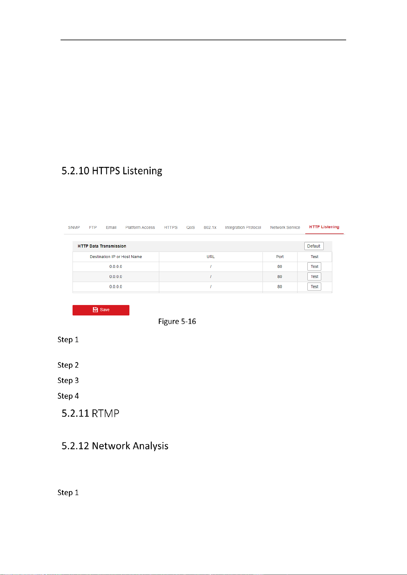
5.2.10 HTTPS Listening ...................................................................................................................................... 51
5.2.11 RTMP ..................................................................................................................................................... 51
5.2.12 Network Analysis ................................................................................................................................... 51
5.2.13 SRTP ....................................................................................................................................................... 52
Chapter 6 Video/Audio Settings ............................................................................................... 54
Video ................................................................................................................................................................... 54
Audio ................................................................................................................................................................... 57
ROI Encoding ....................................................................................................................................................... 58
Target Cropping .................................................................................................................................................. 60
Video Encryption ................................................................................................................................................. 61
Privacy Mask ....................................................................................................................................................... 61
Chapter 7 Image Settings .......................................................................................................... 62
Display Settings ................................................................................................................................................... 62
7.1.1 Day/Night Auto-Switch ............................................................................................................................ 62
7.1.2 Day/Night Scheduled-Switch ................................................................................................................... 66
OSD Settings........................................................................................................................................................ 67
Privacy Mask ....................................................................................................................................................... 69
Picture Overlay ................................................................................................................................................... 70
Chapter 8 Event Settings .......................................................................................................... 71
Basic Events ........................................................................................................................................................ 71
8.1.1 Motion Detection ..................................................................................................................................... 71
8.1.2 Video Tampering Alarm ........................................................................................................................... 77
8.1.3 Exception ................................................................................................................................................. 77
Smart Events ....................................................................................................................................................... 78
8.2.2 Defocus Detection.................................................................................................................................... 80
8.2.3 Scene Change Detection .......................................................................................................................... 81
8.2.4 Intrusion Detection .................................................................................................................................. 82
8.2.5 Line Crossing Detection ........................................................................................................................... 84
8.2.6 Region Entrance Detection ...................................................................................................................... 85
8.2.7 Region Exiting Detection .......................................................................................................................... 86
8.2.8 Loitering Detection .................................................................................................................................. 88
8.2.9 People Gathering Detection..................................................................................................................... 89
8.2.10 Fast Moving Detection ........................................................................................................................... 90

Mobile Network Camera • User Manual
VI
8.2.11 Parking Detection................................................................................................................................... 91
8.2.12 Unattended Baggage Detection ............................................................................................................. 93
8.2.13 Object Removal Detection ..................................................................................................................... 94
Chapter 9 Storage Settings ....................................................................................................... 96
Record Schedule ................................................................................................................................................. 96
Capture Schedule ................................................................................................................................................ 98
Storage Management ......................................................................................................................................... 99
Chapter 10 Access to the Network Camera ............................................................................. 102
10.1.1 Via Static IP Connection ....................................................................................................................... 102
10.1.2 Via Dynamic IP Connection .................................................................................................................. 103
Chapter 11 Appendix .............................................................................................................. 104
Appendix 1 SADP Software Introduction ........................................................................................................ 104
Appendix 2 Device APP ................................................................................................................................... 107
Device Communication Matrix ............................................................................................................................... 107
Device Command .................................................................................................................................................... 107

Mobile Network Camera • User Manual
1
Chapter 1 Introduction
Product Features
This Network camera is a digital monitoring product that integrates video and audio
acquisition, intelligent coding and compression, network transmission and other
functions. With embedded operating system and high-performance hardware
processing platform, it has high stability and reliability, and can meet the needs of
various industries.
Based on Ethernet control, the network camera can realize image compression and
transmit it to different users through the network. Centralized storage based on NAS
can greatly facilitate the storage and call of data.
You can control the webcam through the browser, and set the webcam parameters,
intelligent functions, audio and video parameters, image parameters, etc. through the
browser. Please refer to the actual equipment for specific function parameters.
Product Function
This chapter explains the camera from the product function, so that you can get to
know and get familiar with the camera more quickly.
System function
Video recording and capturing pictures
The camera supports instant capture and video recording during preview, and can also
configure video recording and capture plan after installing memory card or configuring
network storage disk, so as to realize planned video recording and capture.
User Management
You can manage many different users through the administrator "admin" user, and
configure different permissions for each user.
Event detection function
The camera supports basic events and Smart events.
Basic events: Motion Detection, Video Tampering, Exception.
SMART events: Defocus Detection, Scene Change Detection, Object detection,
Intrusion Detection, Line Crossing Detection, Region Entrance Detection, Region
Exiting Detection, Loitering Detection, People Gathering Detection, Fast Moving
Detection, Parking Detection, Unattended Baggage Detection, Object Removal
Detection.
Network function

Mobile Network Camera • User Manual
2
The camera supports TCP/IP, DHCP, UDP, MCAST, SFTP, SNMP and other network
communication protocols; Support open interconnection protocols such as ONVIF.
The function of the product depends on the model, please refer to the technical
parameters of the actual product.
Mobile Network Camera • User Manual
3
Chapter 2 Operation Instructions
You shall acknowledge that the use of the product with Internet access might be
under network security risks. For avoidance of any network attacks and
information leakage, please strengthen your own protection. If the product does
not work properly, please contact with your dealer or the nearest service center.
To ensure the network security of the network camera, we recommend you to
have the network camera assessed and maintained termly. You can contact us if
you need such service.
Before you start:
If you want to set the network camera via a LAN (Local Area Network), please
refer to Section 2.1 Setting the Network Camera over the LAN.
If you want to set the network camera via a WAN (Wide Area Network), please
refer to Section 2.2 Setting the Network Camera over the WAN.
Setting the Network Camera over the LAN
Purpose:
To view and configure the camera via a LAN, you need to connect the network camera
in the same subnet with your computer, and install the SADP or iVMS-4200 software
to search and change the IP of the network camera.
For the detailed introduction of SADP, please refer to Appendix 1.
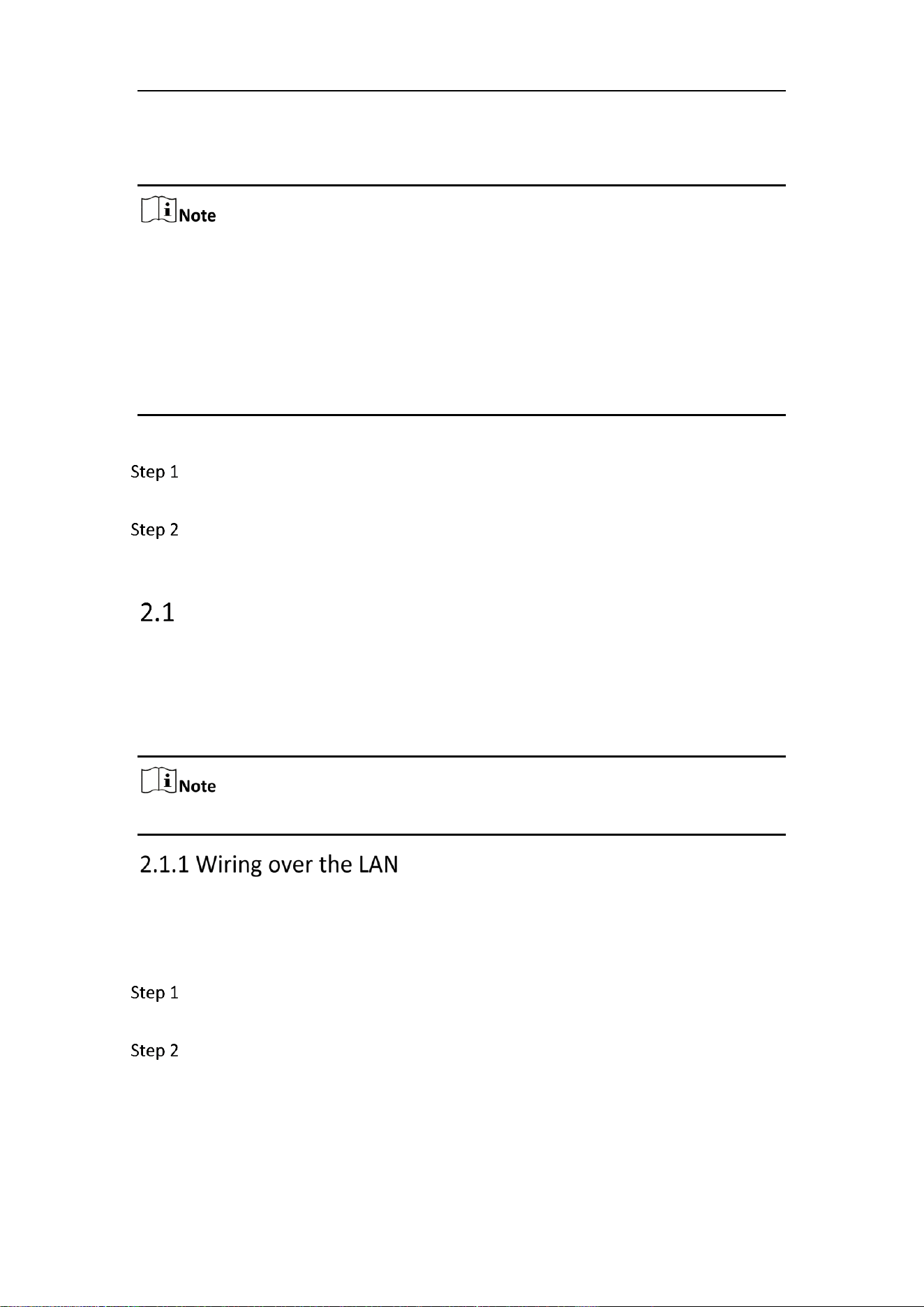
The following figures show the two ways of cable connection of a network camera and
a computer:
Purpose:
To test the network camera, you can directly connect the network camera to the
computer with a network cable as shown in Figure 2-1.
Refer to the Figure 2-2 to set network camera over the LAN via a switch or a
router.
Mobile Network Camera • User Manual
4
半球
Network Cable
or
Network Camera
Computer
Connecting Directly
网络交换机
半球
Network Cable
Network Cable
or
or
Network Camera Computer
Connecting via a Switch or a Router
Activating the Camera
You are required to activate the camera first by setting a strong password for it before
you can use the camera.
Activation via Web Browser, Activation via SADP, and Activation via Client Software are
all supported.
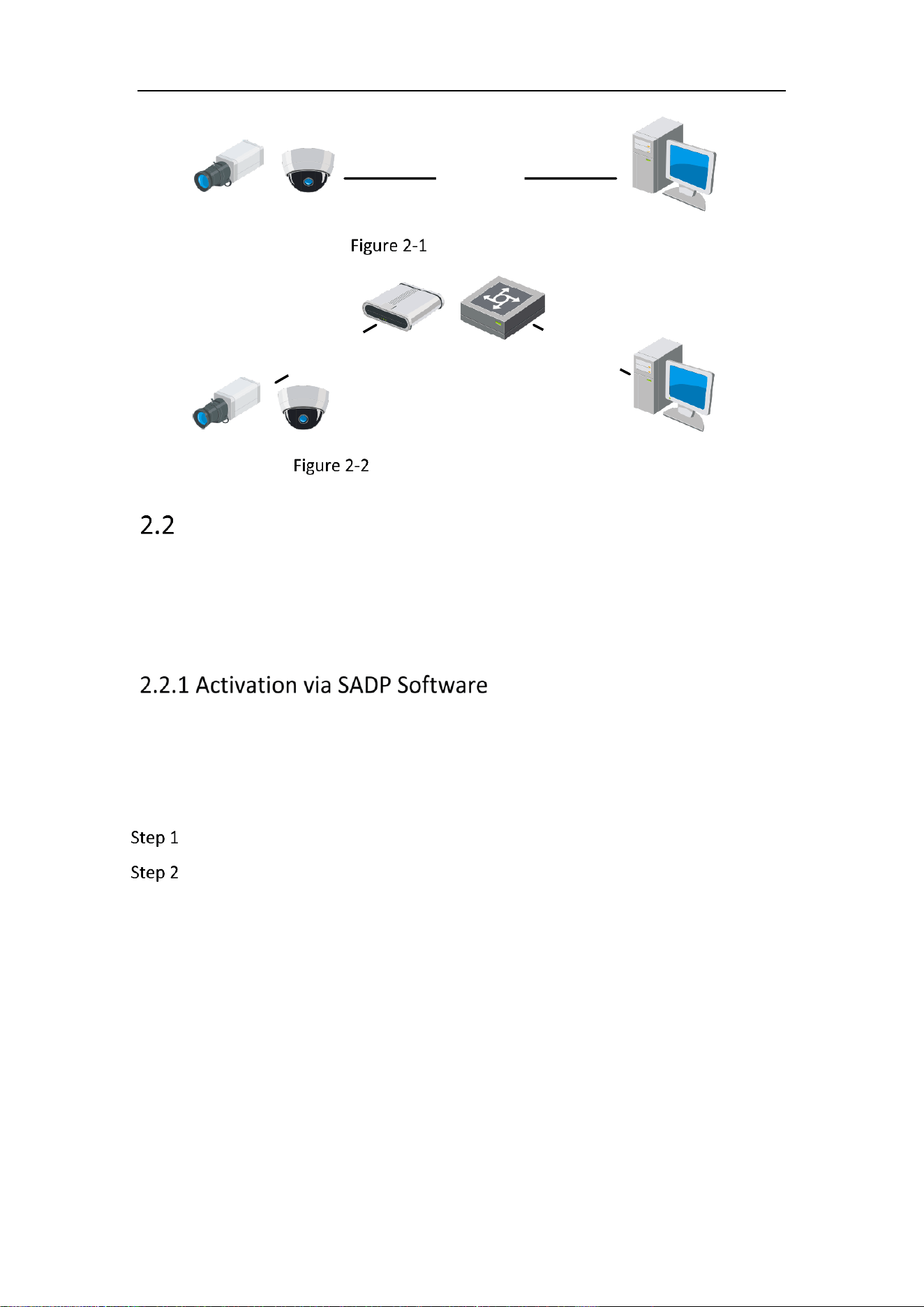
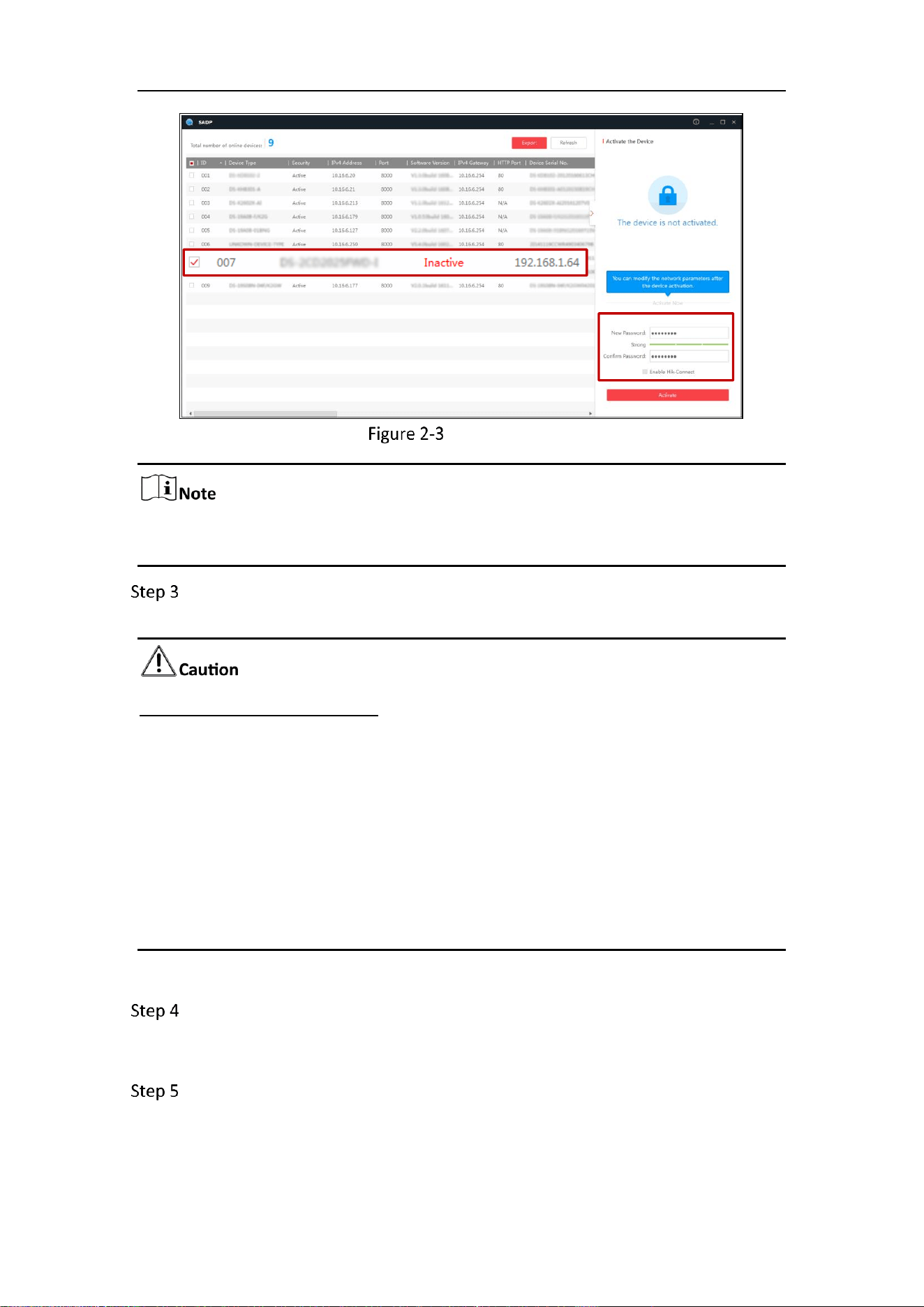
SADP software is used for detecting the online device, activating the camera, and
resetting the password.
Get the SADP software from the official website, and install the SADP according to the
prompts. Follow the steps to activate the camera.
Run the SADP software to search the online devices.
Check the device status from the device list, and select the inactive device.
Mobile Network Camera • User Manual
5
SADP Interface
The SADP software supports activating the camera in batch. Refer to the user manual
of SADP software for details.
Create and input the password in the password field, and confirm the password.
A password with user name in it is not allowed.
STRONG PASSWORD RECOMMENDED
We highly recommend you create a strong password of your own choosing
(using a minimum of 8 characters, including at least three of the following
categories: upper case letters, lower case letters, numbers, and special
characters) in order to increase the security of your product. And we
recommend you reset your password regularly, especially in the high security
system, resetting the password monthly or weekly can better protect your
product.
Proper configuration of all passwords and other security settings is the
responsibility of the installer and/or end-user.
You can enable the Hik-Connect service for the device during activation.
Click Activate to start activation. You can check whether the activation is
completed on the popup window. If activation failed, please make sure that the
password meets the requirement and try again.
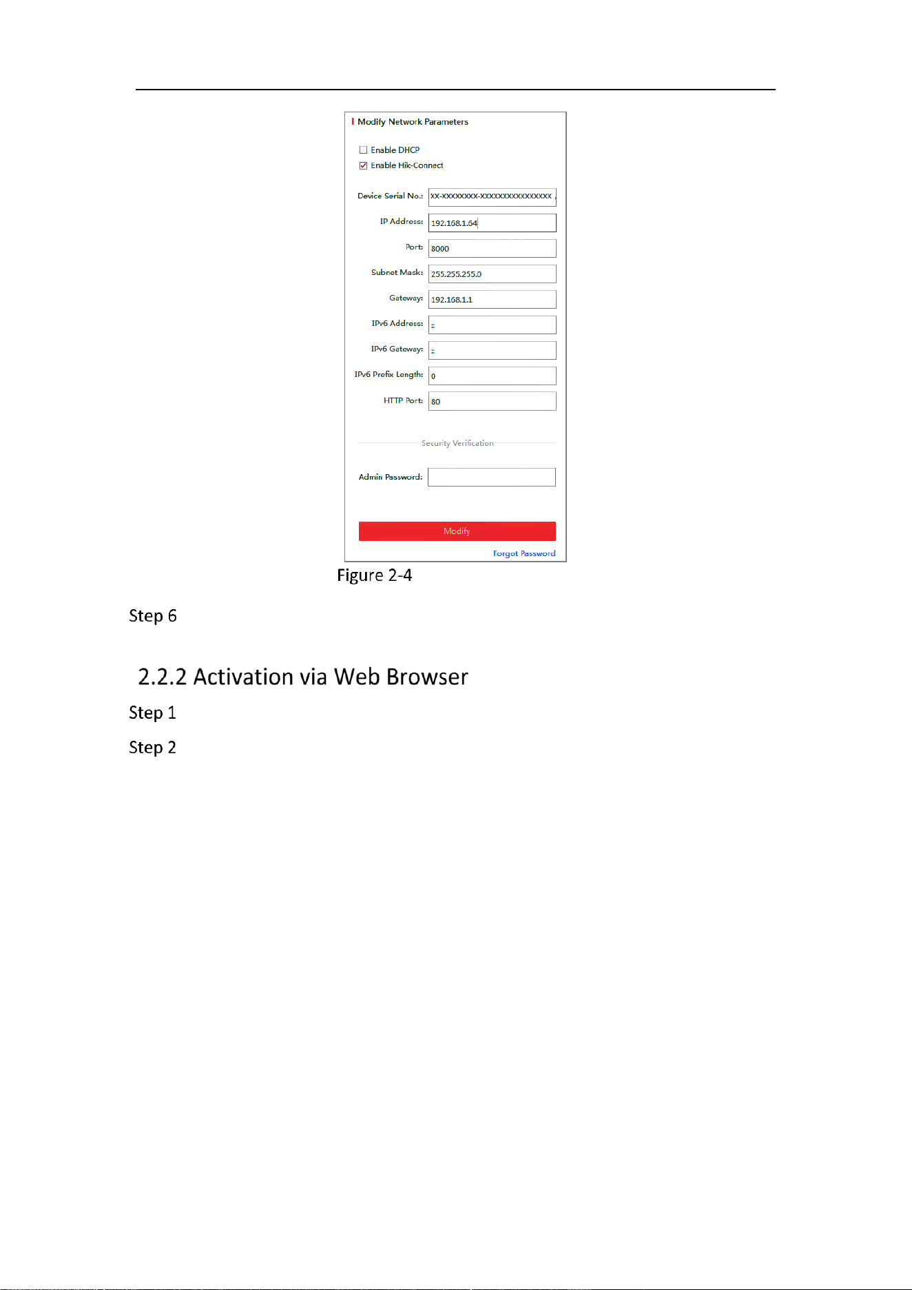
Change the device IP address to the same subnet with your computer by either
modifying the IP address manually or checking the checkbox of Enable DHCP.
Select inactive device.
Input and confirm
password.
Mobile Network Camera • User Manual
6
Modify the IP Address
Input the admin password and click Modify to activate your IP address
modification.
Power on the camera, and connect the camera to the network.
Input the IP address into the address bar of the web browser, and click Enter to
enter the activation interface.
Mobile Network Camera • User Manual
7
The default IP address of the camera is 192.168.1.64.
The computer and the camera should belong to the same subnet.
For the camera enables the DHCP by default, you need to use the SADP software
to search the IP address.
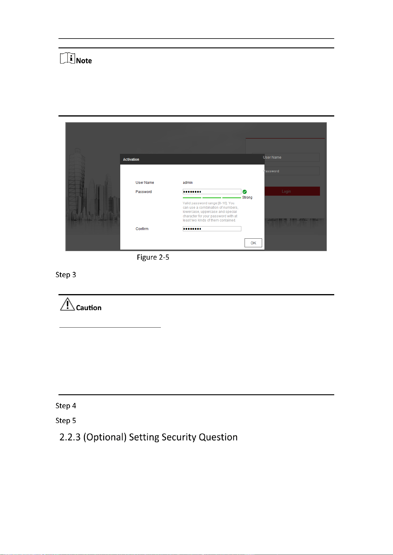
Activation via Web Browser
Create and input a password into the password field. A password with user name
in it is not allowed.
STRONG PASSWORD RECOMMENDED
We highly recommend you create a strong password of your own choosing (using a
minimum of 8 characters, including at least three of the following categories: upper
case letters, lower case letters, numbers, and special characters) in order to increase
the security of your product. And we recommend you reset your password regularly,
especially in the high security system, resetting the password monthly or weekly can
better protect your product.
Confirm the password.
Click OK to save the password and enter the live view interface.
Security question is used to reset the admin password when admin user forgets the
password.
Admin user can follow the pop-up window to complete security question settings
during camera activation. Or, admin user can go to User Management interface to set
up the function.
Mobile Network Camera • User Manual
8
Login and Logout
For certain camera models, HTTPS is enabled by default and the camera creates an
unsigned certificate automatically. When you access to the camera the first time, the
web browser prompts a notification about the certificate issue.
To cancel the notification, install a signed-certificate to the camera.
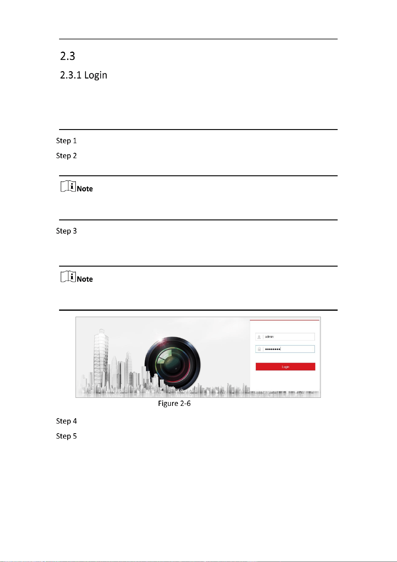
Open the web browser.
In the browser address bar, input the IP address of the network camera, and
press the Enter key to enter the login interface.
The default IP address is 192.168.1.64. You are recommended to change the IP
address to the same subnet with your computer.
Input the user name and password.
The admin user should configure the device accounts and user/operator permissions
properly. Delete the unnecessary accounts and user/operator permissions.
The IP address gets locked if the admin user performs 7 failed password attempts (5
attempts for the user/operator).
Login Interface
Click Login.
(Optional) Install the plug-in before viewing the live video and operating the
camera. Follow the installation prompts to install the plug-in.
Mobile Network Camera • User Manual
9
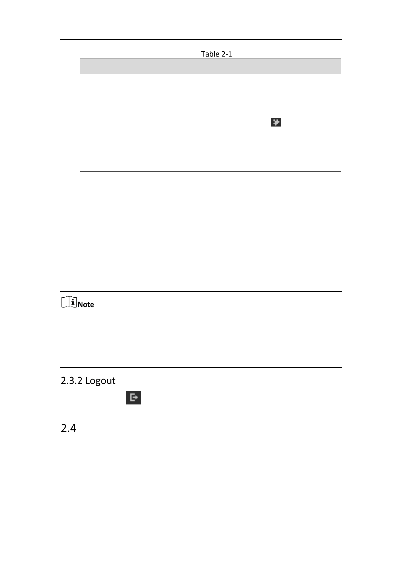
Install Plugins
OS
Browser Version
Plugin
Windows
IE 8 and upper
Google Chrome 57 and lower
Mozilla Firefox 52 and lower
Install the plugin
according to instructions.
Google Chrome 57 and upper
Mozilla Firefox 52 and upper
Click in the preview
page to download and
install the plugin for high
quality view and device
functions.
Mac OS
Google Chrome 57 and upper
Mozilla Firefox 52 and upper
Mac Safari 16 and upper
To preview, enter
Configuration > Network >
Advanced Setting >
Network Service, and
enbale WebSocket. Some
functions will be limited
after enbling this function,
such as video play. The
actual equipment shall
prevail.
For camera that supports plug-in free live view, if you are using Google Chrome 57
and its above version or Mozilla Firefox 52 and its above version, plug-in installation
is not required. But Picture and Playback functions are hidden. To use mentioned
function via web browser, change to their lower version, or change to Internet
Explorer 8.0 and above version.
To logout, click the icon.
Main Interface
The main interface is shown as follows.
Mobile Network Camera • User Manual
10
Main Interface
Live View: to view the camera and set parameters.
Playback: to play recordings according to their type and time.
Picture: to search, view and download the pictures stored in the SD Card of the
network camera.
Configuration: to set the system and function parameters.
The interface may vary according to the model of the camera.
Mobile Network Camera • User Manual
11
Chapter 3 Basic Functions
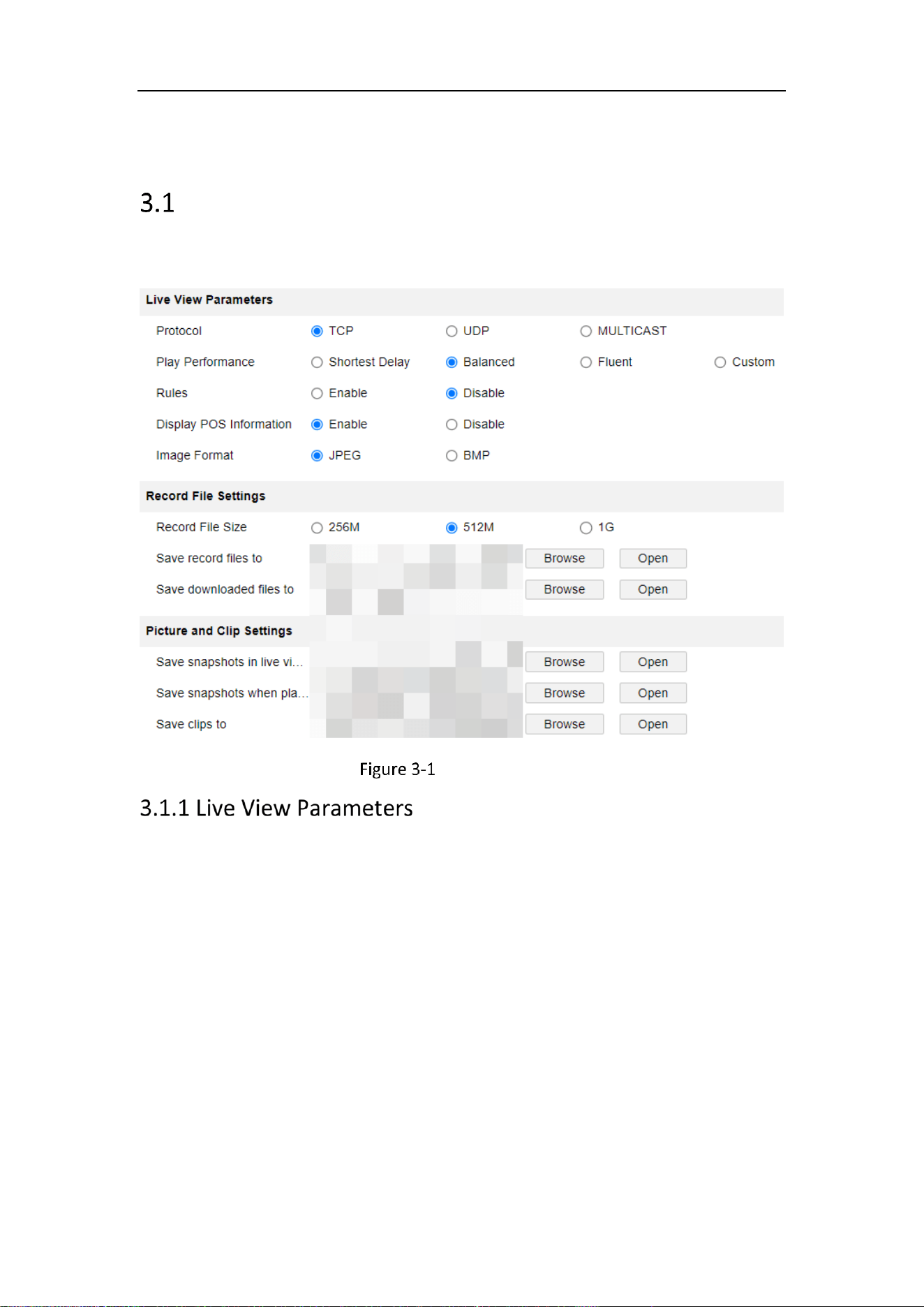
Local Parameters
Go to Configuration > Local to configure local configurations. Live View Parameters,
Record File Settings, Picture and Clip Settings can be configured.
Local Parameters
Protocols
TCP, UDP and MULTICAST protocols are supported.
− The default protocol is TCP
− UDP is suitable for the situation that the requirement of video fluency
is not high and the network environment is unstable.
− MULTICAST is suitable for multicast addresses with many customers
and need to be configured before selection.
Playback performance:
You can choose the shortest delay, Balanced, Fluent and Custom, and the default is
Custom.
Minimum delay: Real-time is good, but it may affect the fluency of video.
Balanced: Give consideration to the real-time and fluency of video playback.
Mobile Network Camera • User Manual
12
Good fluency: In the same network situation, it takes up less network resources,
and the video is smoother than other modes.
Custom: the frame rate can be set according to the network conditions.
Information: You can choose to enable or disable it. When enabled, information
boxes will appear on the live screen, including the dynamic analysis box of motion
detection and the face target box.
POS information overlay: it can be enabled or disabled. When enabled, when a
target triggers a rule, the live screen will display the attribute information of the
target.
Picture and Clip Settings: set the format of captured pictures, with optional JPEG
and BMP.
Record File Size: it can be set to 256 M, 512 M and 1 G, indicating the size of a
single video file stored locally.
Save record files to: the path where video files are stored locally. You can choose
Browse to change the path, and click Open Folder to open the folder under the
archive path.
Save downloaded files to: the path where the video files saved during playback
are stored locally. You can choose Browse to change the path, and click Open Folder
to open the folder under the archive path.
Save snapshots in live view to: the path where the captured pictures are stored
locally during preview. You can choose Browse to change the path, and click Open
Folder to open the folder under the archive path.
Save snapshots when playback to: the path where captured pictures are stored
locally during playback. You can choose Browse to change the path, and click Open
Folder to open the folder under the archive path.
Save clips to: the path where the cut video files are stored locally during
playback. You can choose Browse to change the path, and click Open Folder to open
the folder under the archive path.
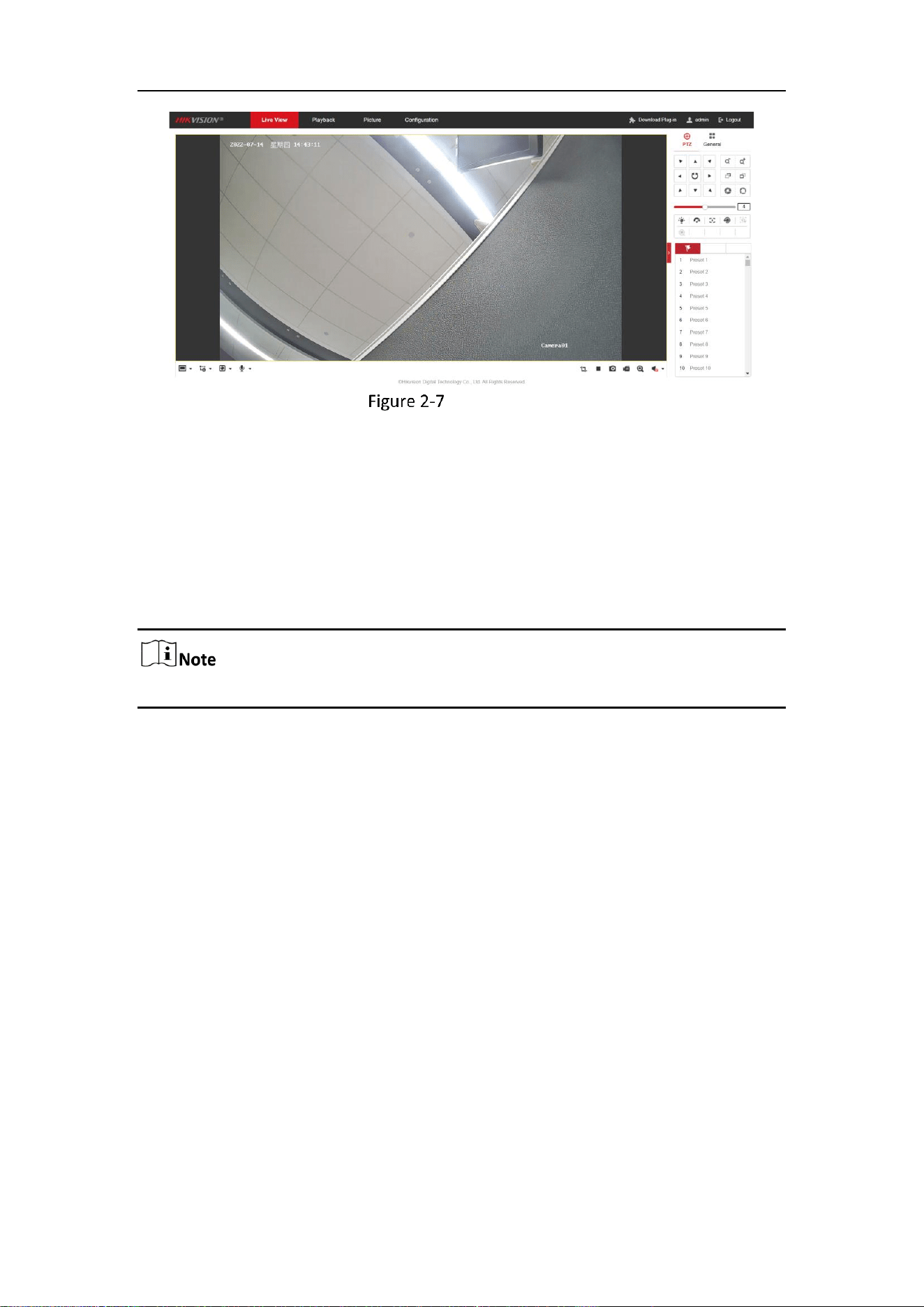
Live View
Purpose:
The live view page allows you to view the real-time video, capture images, realize PTZ
control, set/call presets and configure video parameters.
Log in the network camera to enter the live view page, or you can click Live View on
the menu bar of the main page to enter the live view page.
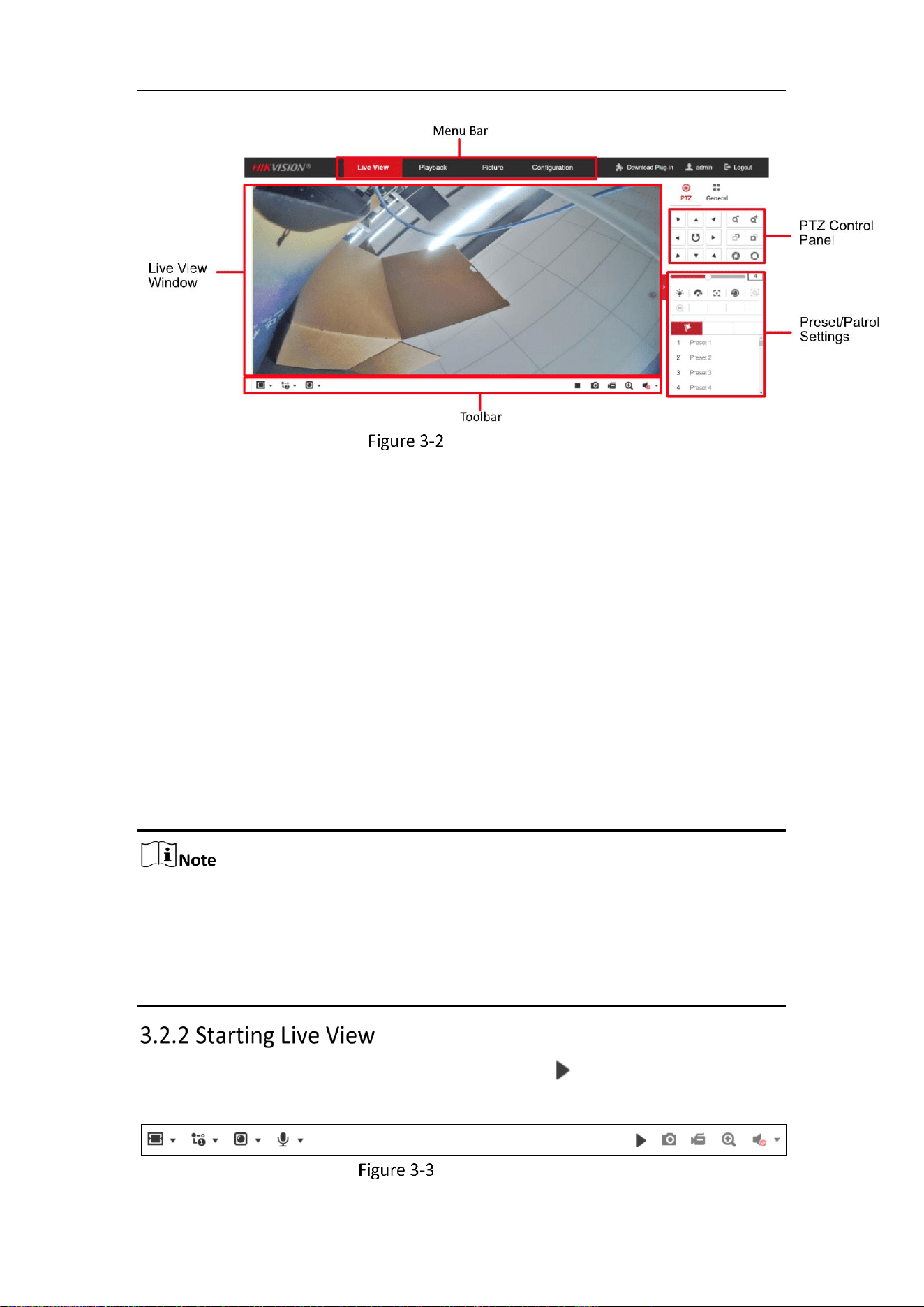
Descriptions of the live view page:
Mobile Network Camera • User Manual
13
Live View Page
Menu Bar
Click each tab to enter Live View, Playback, Picture, Application, and Configuration
page respectively.
Live View Window
Display the live video.
Toolbar
Toolbar allows you to adjust the live view window size, the stream type, and the plug-
ins. It also allows you to process the operations on the live view page, e.g., start/stop
live view, capture, record, audio on/off, two-way audio, start/stop digital zoom, etc.
For IE (Internet Explorer) users, plug-ins as webcomponents and quick time are
selectable. And for Non-IE users, webcomponents, quick time, VLC or MJPEG are
selectable if they are supported by the web browser.
For camera that supports plug-in free live view, when Google Chrome 45 and its
above version or Mozilla Firefox 52 and its above version are used, plug-in installation
is not required. But Picture and Playback functions are hidden. To use mentioned
function via web browser, change to their lower versions, or change to Internet
Explorer 8.0 and its above version.
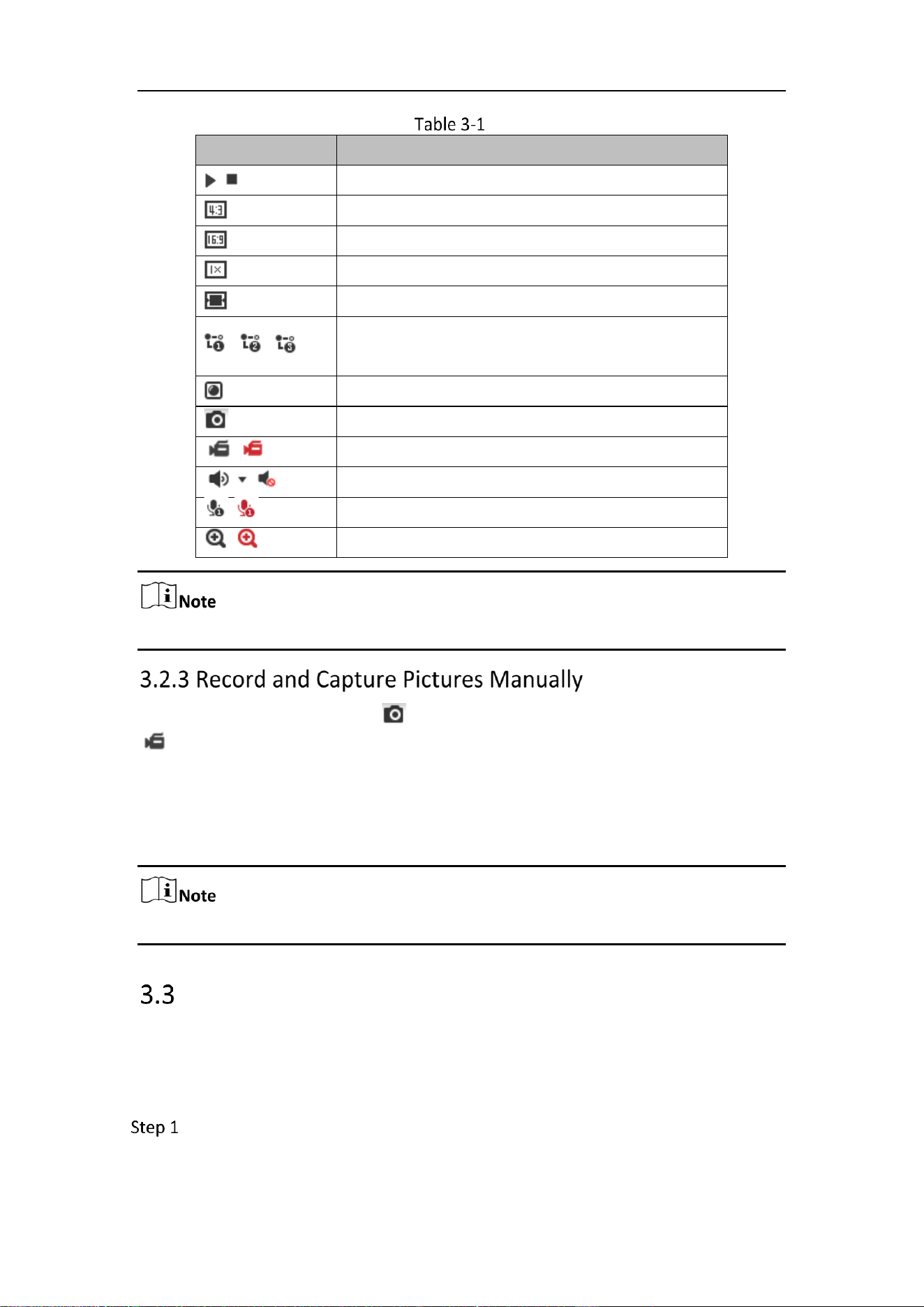
In the live view window as shown in Figure 4-2, click on the toolbar to start the
live view of the camera.
Live View Toolbar
Mobile Network Camera • User Manual
14
Descriptions of the Toolbar
Icon
Description
/
Start/Stop live view.
The window size is 4:3.
The window size is 16:9.
The original widow size.
Self-adaptive window size.
, , , etc.
Live view with the different video streams.
Supported video streams vary according to camera models.
Click to select the third-party plug-in.
Manually capture the picture.
/
Manually start/stop recording.
/
Audio on and adjust volume /Mute.
/
Turn on/off microphone.
/
Start/stop digital zoom function.
The icons vary according to the different camera models.
In the live view interface, click on the toolbar to capture the live pictures; click
to record the live view. The saving paths of the captured pictures and clips can be
set on the Configuration > Local page. To configure remote scheduled recording, please
refer to 9.1 Record Schedule.
The captured image will be saved as a JPEG file or BMP file in your computer.
Playback
Purpose:
This section explains how to view the remotely recorded video files stored in the
network disks or SD cards.
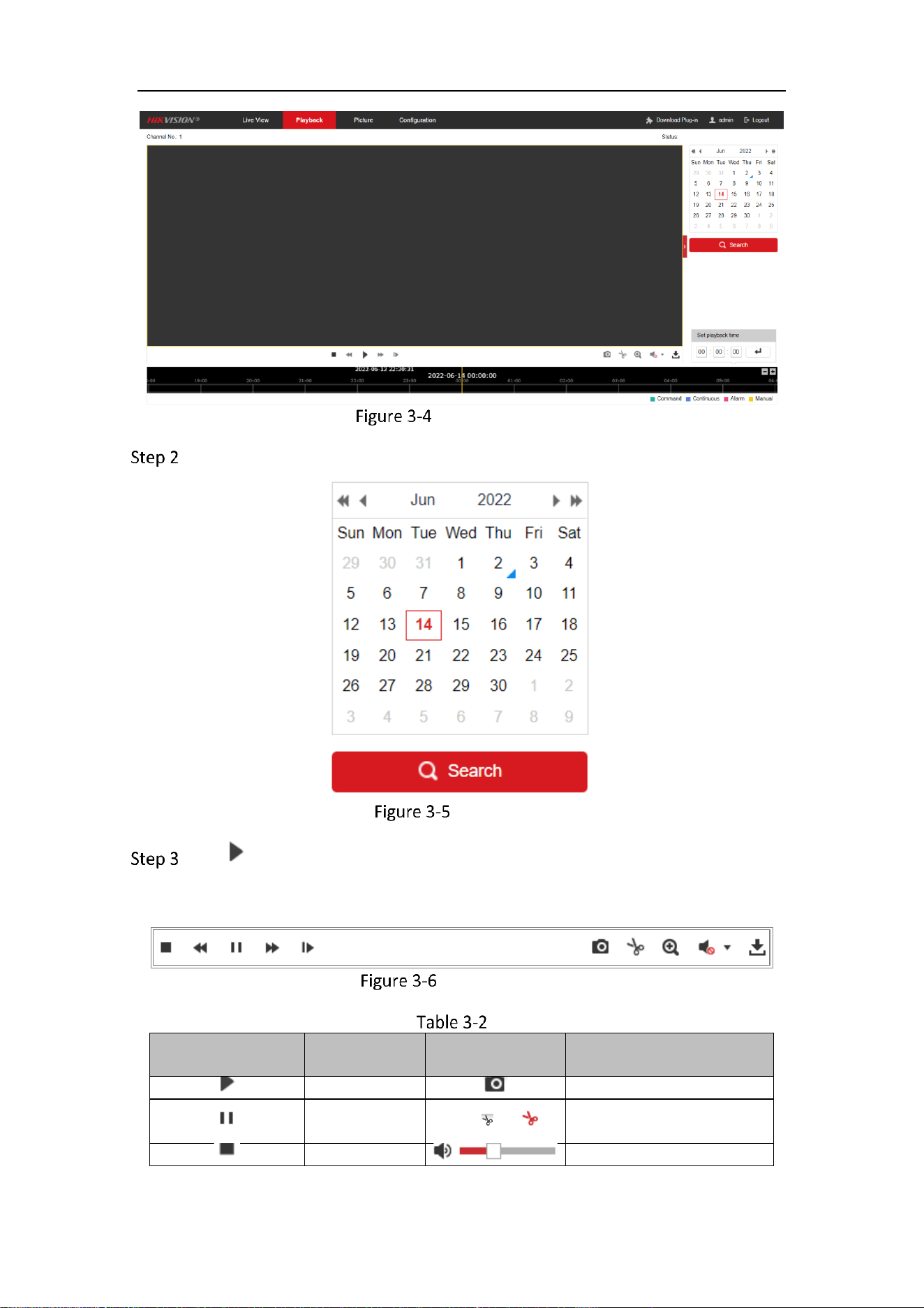
Click Playback on the menu bar to enter playback interface.
Mobile Network Camera • User Manual
15
Playback Interface
Select the date and click Search.
Search Video
Click to play the video files found on this date.
The toolbar on the bottom of Playback interface can be used to control playing
process.
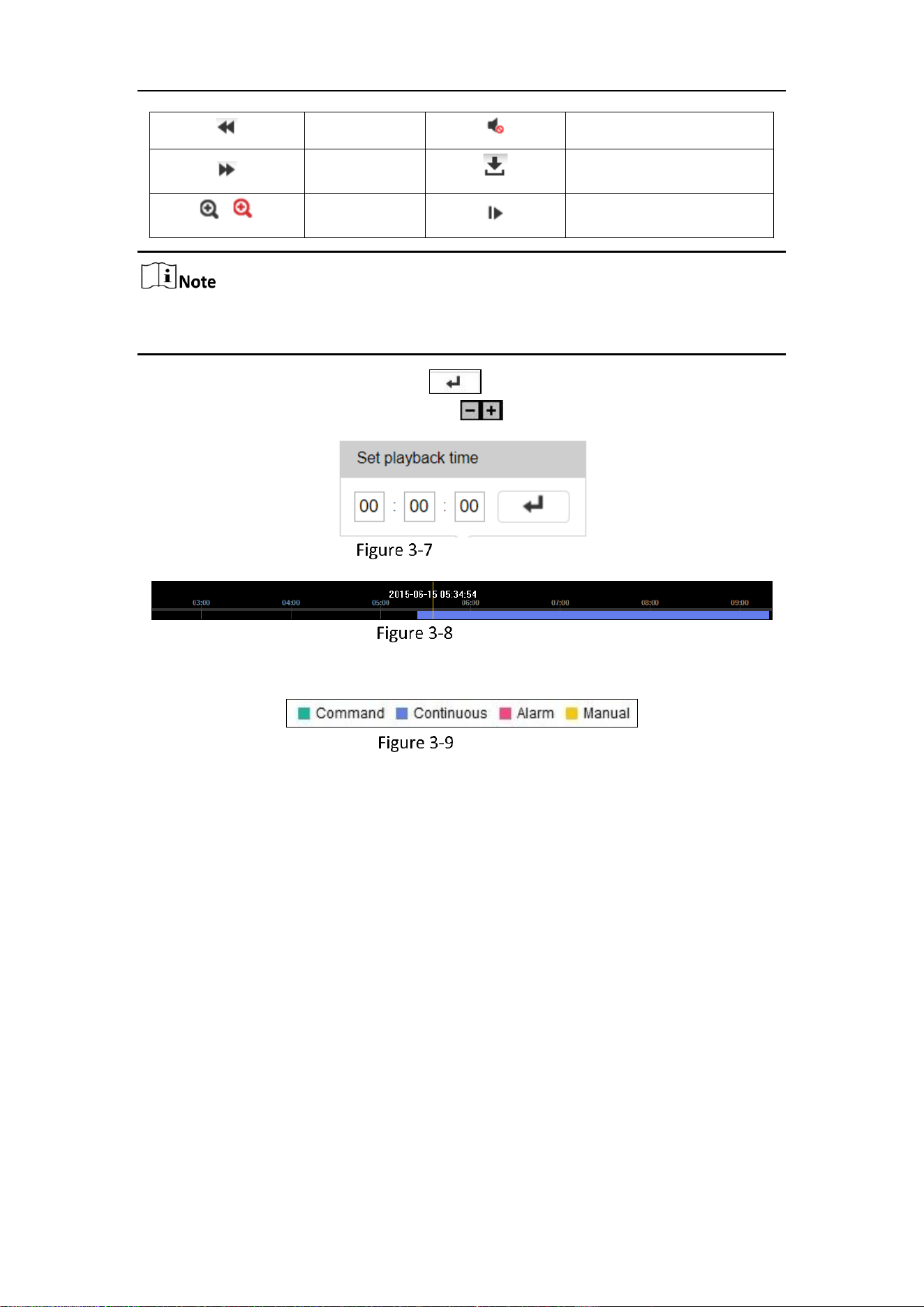
Playback Toolbar
Description of the buttons
Button
Operation
Button
Operation
Play
Capture a picture
Pause
/
Start/Stop clipping video
files
Stop
Audio on and adjust volume
Mobile Network Camera • User Manual
16
Speed down
Mute
Speed up
Download
/
Enable/Disable
digital zoom
Playback by frame
You can choose the file paths locally for downloaded playback video files and pictures
in Local Configuration interface.
You can also input the time and click to locate the playback point in the Set
playback time field. You can also click to zoom out/in the progress bar.
Set Playback Time
Progress Bar
The different colors of the video on the progress bar stand for the different video types.
Video Types
Mobile Network Camera • User Manual
17
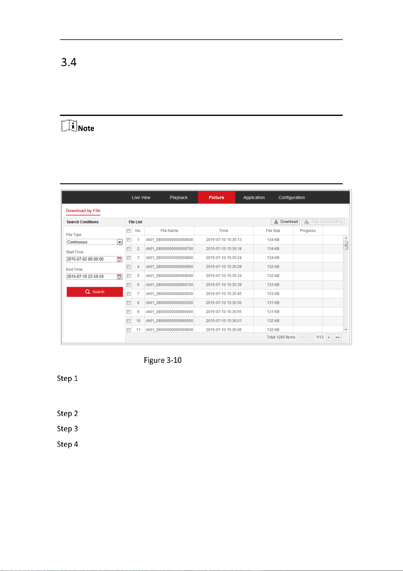
Picture
Purpose:
Click Picture to enter the picture searching interface. You can search, view, and
download the pictures stored in the local storage or network storage.
Make sure HDD, NAS or memory card are properly configured before you
process the picture search.
Make sure the capture schedule is configured. Go to Configuration > Storage >
Schedule Settings > Capture to set the capture schedule.
Picture Search Interface
Select the file type from the dropdown list. Continuous, Motion, Alarm, Motion
| Alarm, Motion & Alarm, Line Crossing, Intrusion Detection, and Scene Change
Detection are selectable.
Select the start time and end time.
Click Search to search the matched pictures.
Check the checkbox of the pictures and then click Download to download the
selected pictures.

Mobile Network Camera • User Manual
18
Up to 4000 pictures can be displayed at one time.
Mobile Network Camera • User Manual
19
Chapter 4 System Configuration
Configure System Settings
Purpose:
Follow the instructions below to configure the system settings, include System Settings,
Maintenance, Security, and User Management, etc.
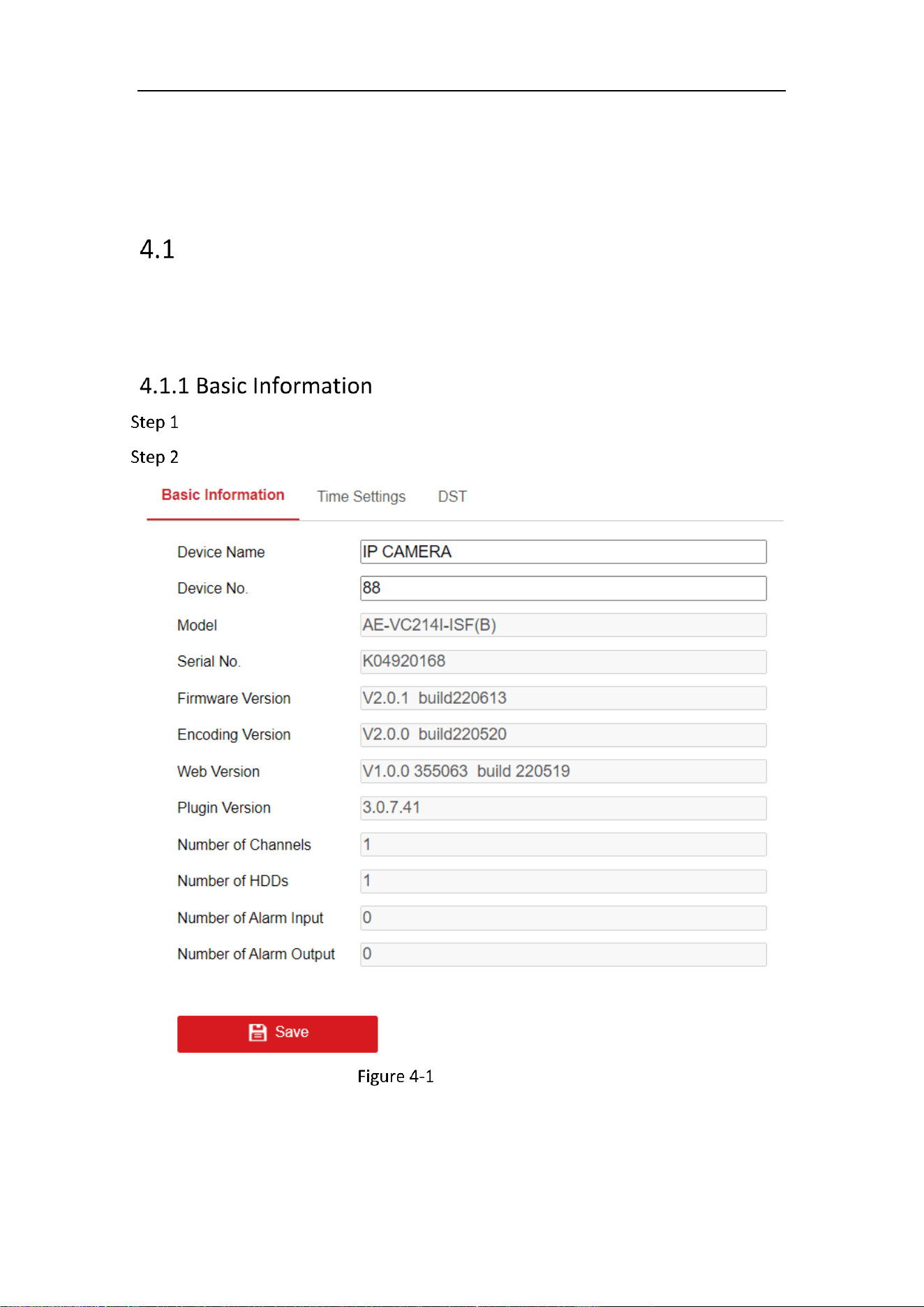
Go to Configuration > System > System Settings > Basic Information.
Edit the Device Name and Device No.
Basic Information
Mobile Network Camera • User Manual
20
Other information of the network camera, such as Model, Serial No., Firmware
Version, Encoding Version, Number of Channels, Number of HDDs, Number of Alarm
Input and Number of Alarm Output are displayed. The information cannot be
changed in this menu. These options are the reference for maintenance or
modification in future.
Purpose:
You can follow the instructions in this section to configure the time synchronization
and DST settings.
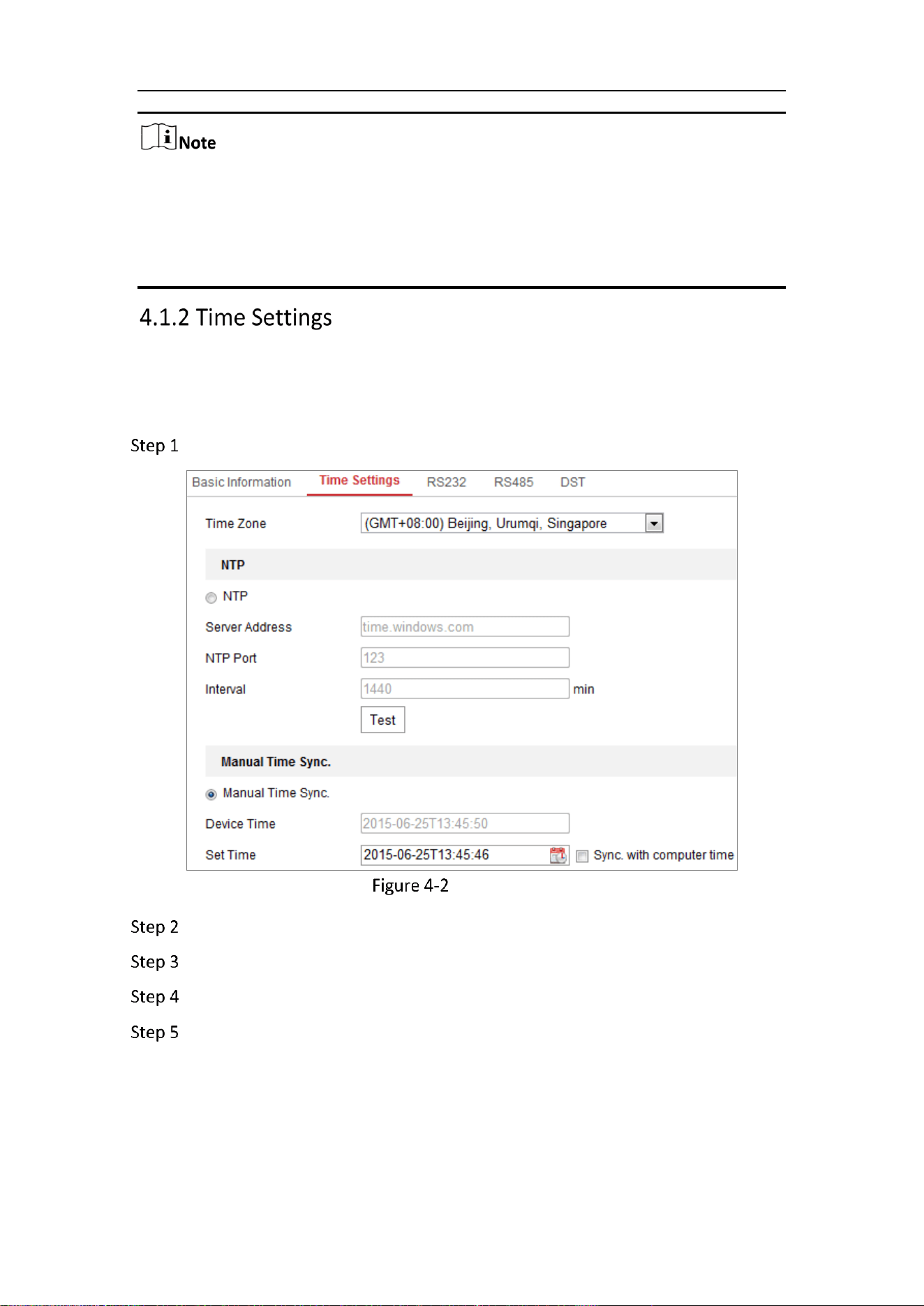
Go to Configuration > System> System Settings > Time Settings.
Time Settings
Select the Time Zone of your location from the drop-down menu.
Configure the NTP settings.
Click to enable the NTP function.
Configure the following settings:
Server Address: IP address of NTP server.
NTP Port: Port of NTP server.
Interval: The time interval between the two synchronizing actions with NTP
server.
Mobile Network Camera • User Manual
21
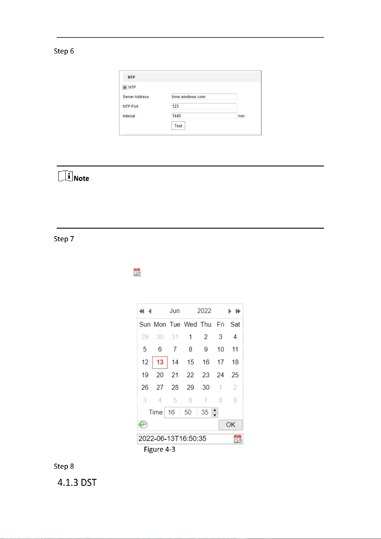
(Optional) You can click the Test button to test the time synchronization function
via NTP server.
Time Sync by NTP Server
If the camera is connected to a public network, you should use a NTP server that has
a time synchronization function, such as the server at the National Time Center (IP
Address: 210.72.145.44). If the camera is set in a customized network, NTP software
can be used to establish a NTP server for time synchronization.
Configure the manual time synchronization.
1) Check the Manual Time Sync. item to enable the manual time
synchronization function.
2) Click the icon to select the date, time from the pop-up calendar.
3) (Optional) You can check Sync. with computer time item to synchronize the
time of the device with that of the local PC.
Time Sync Manually
Click Save to save the settings.
Mobile Network Camera • User Manual
22
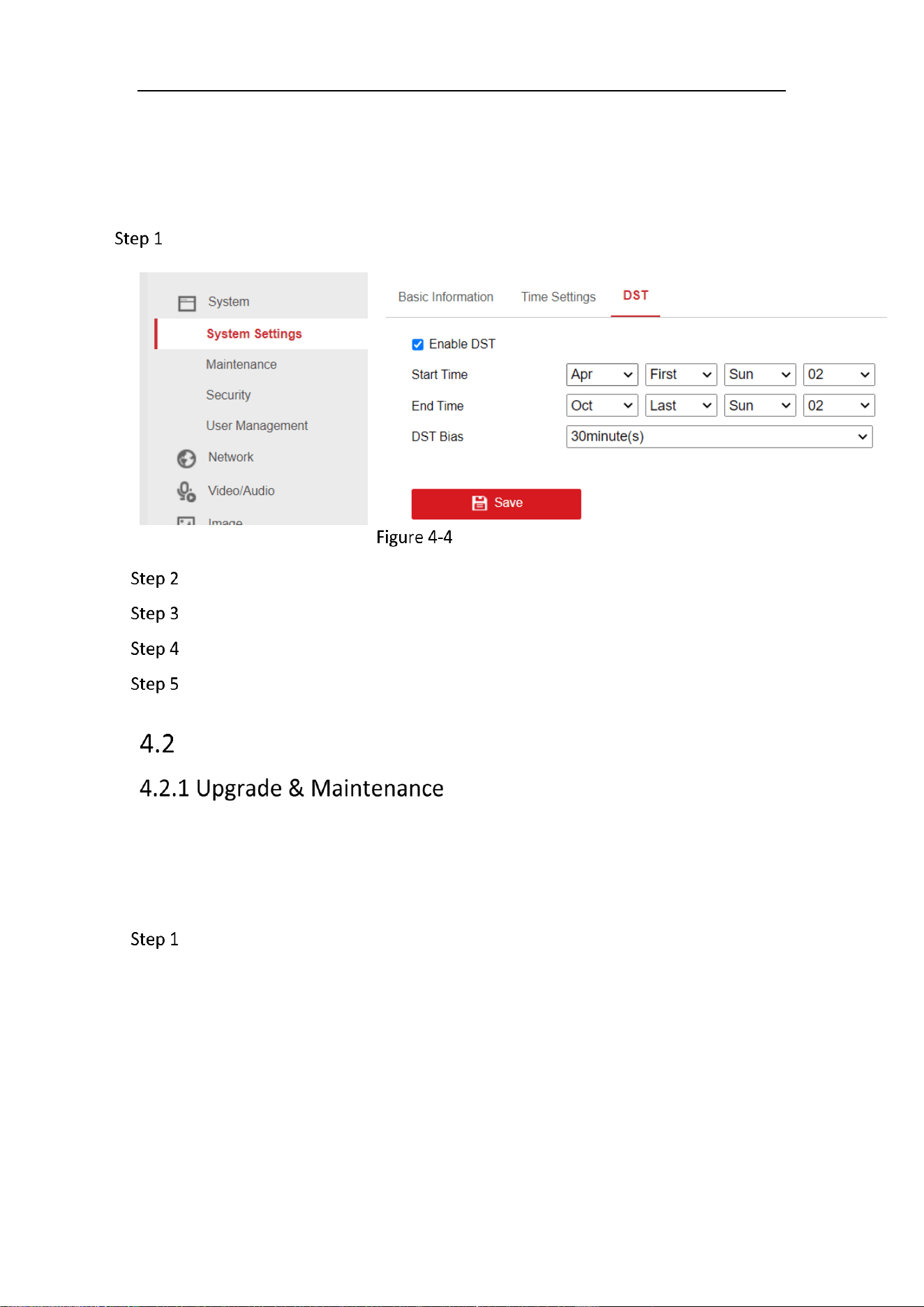
Purpose:
Daylight Saving Time (DST) is a way of making better use of the natural daylight by
setting your clock forward one hour during the summer months, and back again in the
fall.
Go to Configuration > System > System Settings > DST
DST Settings
Check Enable DST.
Select the start time and the end time.
Select the DST Bias.
Click Save to activate the settings.
Maintenance
Purpose:
The upgrade & maintenance interface allows you to process the operations, including
reboot, partly restore, restore to default, export/import the configuration files, and
upgrade the device.
Go to Configuration > System > Maintenance > Upgrade & Maintenance.
Reboot: Restart the device.
Restore: Reset all the parameters, except the IP parameters and user
information, to the default settings.
Default: Restore all the parameters to the factory default.

Mobile Network Camera • User Manual
23
After restoring the default settings, the IP address is also restored to the default
IP address, please be careful for this action.
For camera that supports Wi-Fi, wireless dial, or wlan function, Restore action
does not restore the related settings of mentioned functions to default.
Information Export
Device Parameters: click to export the current configuration file of the camera.
This operation requires admin password to proceed.
For the exported file, you also have to create an encryption password. The encryption
password is required when you import the file to other cameras.
Diagnose Information: click to download log and system information.
Import Config. File
Configuration file is used for the batch configuration of the cameras.
Click Browse to select the saved configuration file.
Click Import and input the encryption password that you set during exporting.
The camera needs rebooting after importing configuration file.
Upgrade: Upgrade the device to a certain version.
Select firmware or firmware directory to locate the upgrade file.
Firmware: Locate the exact path of the upgrade file.
Firmware Directory: Only the directory the upgrade file belongs to is required.
Click Browse to select the local upgrade file and then click Upgrade to start
remote upgrade.
The upgrading process will take 1 to 10 minutes. Please don't disconnect power of
the camera during the process, and the camera reboots automatically after upgrade.
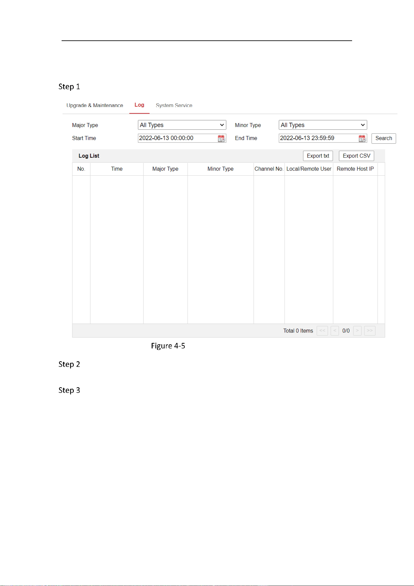
Purpose:
The operation, alarm, exception and information of the camera can be stored in log
files. You can also export the log files on your demand.
Mobile Network Camera • User Manual
24
Before you start:
Please configure network storage for the camera or insert a SD card in the camera.
Go to Configuration > System > Maintenance > Log.
Log Searching Interface
Set the log search conditions to specify the search, including the Major Type,
Minor Type, Start Time and End Time.
Click Search to search log files. The matched log files will be displayed on the log
list interface.
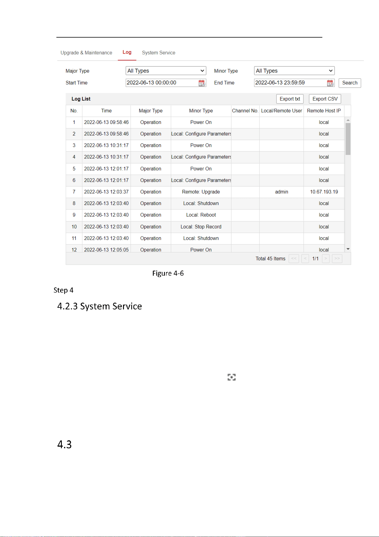
Mobile Network Camera • User Manual
25
Log Searching
To export the log files, click Export to save the log files.
Purpose:
System service settings refer to the hardware service the camera supports. Supported
functions vary according to the different cameras. For the cameras support IR Light,
ABF (Auto Back Focus), Auto Defog, or Status LED, you can select to enable or disable
the corresponding service according to the actual demands.
ABF: When ABF function is enabled, you can click on PTZ control panel to
realize auxiliary focus.
Third Stream: For some models, third stream is not enabled by default. Check
Enable Third Stream to enable the function. When the Third Stream is enabled, the
smart event will not be supported.
Security
Configure the parameters, including Authentication, IP Address Filter, and Security
Service from security interface.
Mobile Network Camera • User Manual
26
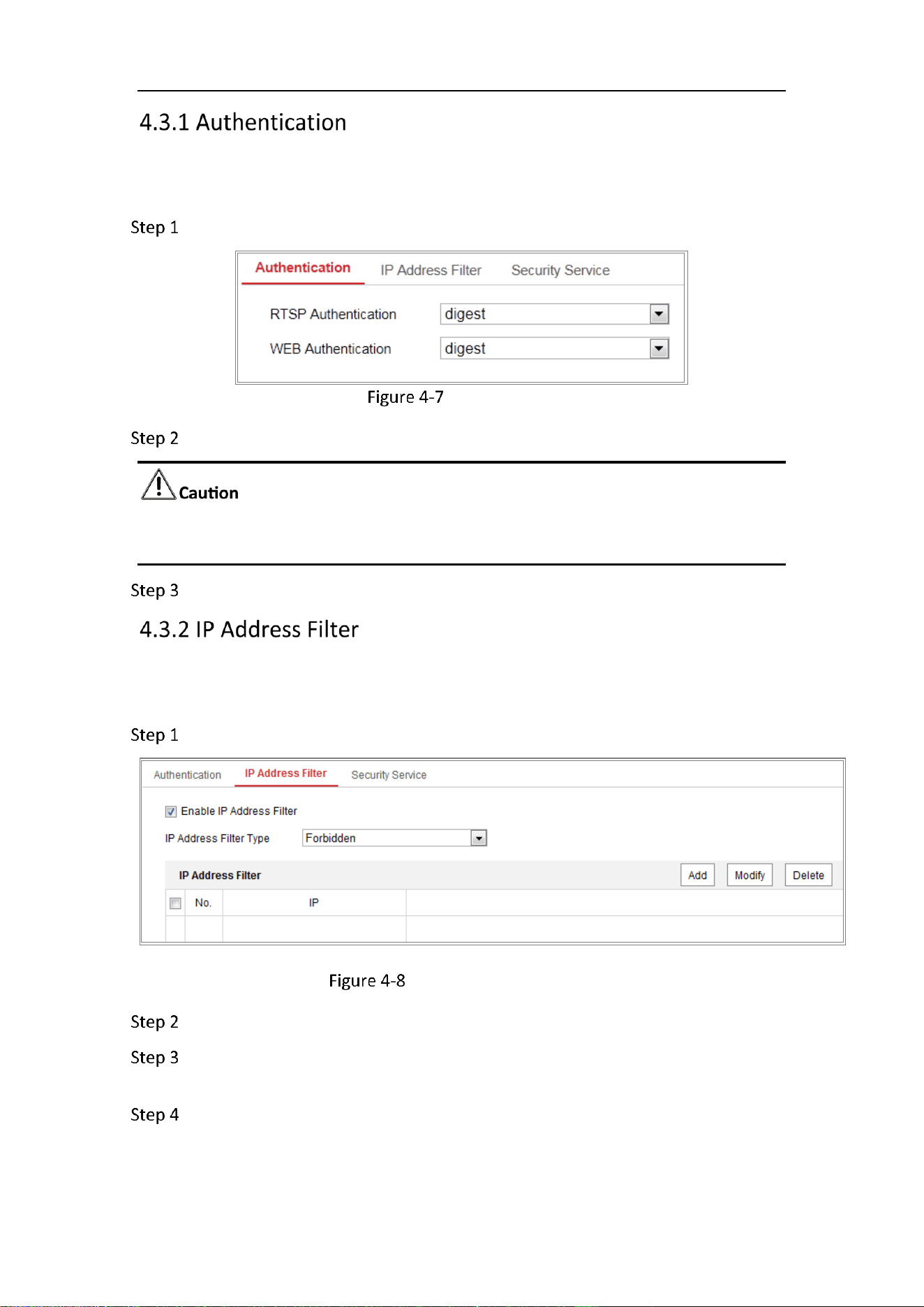
Purpose:
You can specifically secure the stream data of live view.
Go to Configuration > System > Security > Authentication.
Authentication
Set up authentication method for RTSP authentication and WEB authentication.
Digest is the recommended authentication method for better data security. You must
be aware of the risk if you adopt basic as the authentication method.
Click Save.
Purpose:
This function makes it possible for access control.
Go to Configuration > System > Security > IP Address Filter
IP Address Filter Interface
Check the checkbox of Enable IP Address Filter.
Select the type of IP Address Filter in the drop-down list, Forbidden and Allowed
are selectable.
Set the IP Address Filter list.
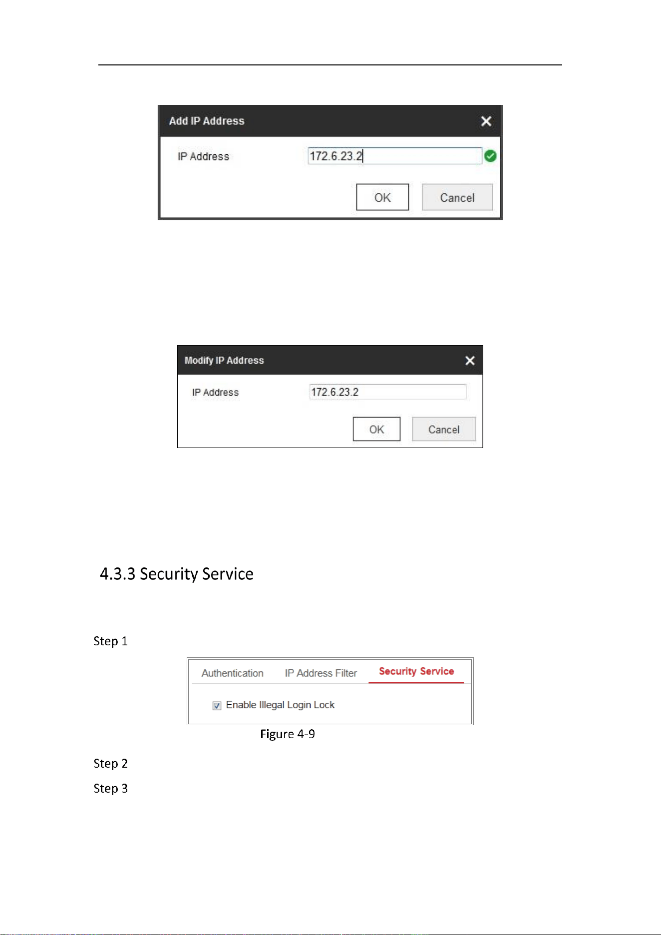
Add an IP Address
1) Click the Add to add an IP.
Mobile Network Camera • User Manual
27
2) Input the IP Adreess.
Add an IP
3) Click the OK to finish adding.
Modify an IP Address
1) Left-click an IP address from filter list and click Modify.
2) Modify the IP address in the text filed.
Modify an IP
3) Click the OK to finish modifying.
Delete an IP Address or IP Addresses.
1) Select the IP address(es) and click Delete.
2) Click Save to save the settings.
To enable the remote login, and improve the data communication security, the camera
provides the security service for better user experience.
Go to Configuration > System > Security > Security Service.
Security Service
Check the checkbox of Enable Illegal Login Lock.
Illegal Login Lock: it is used to limit the user login attempts. Login attempt from
the IP address is rejected if admin user performs 7 failed user name/password
attempts (5 times for the operator/user).
Mobile Network Camera • User Manual
28
If the IP address is rejected, you can try to login the device after 30 minutes.
User Management
Administrator
The admin user can add, delete or modify user accounts, and grant them different
permissions. We highly recommend you manage the user accounts and permissions
properly.
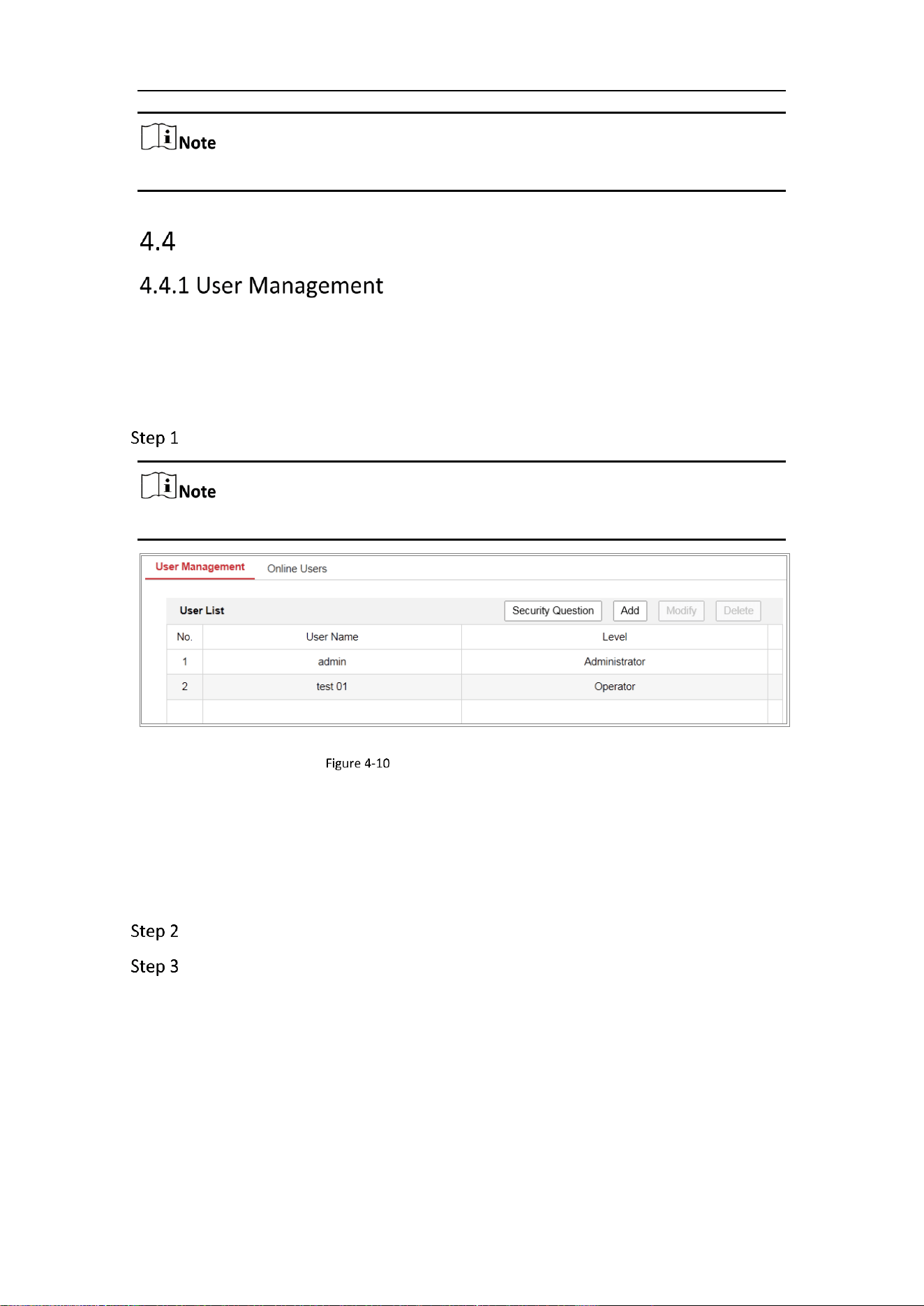
Go to Configuration > System > User Management.
Admin password if required for adding and modifying a user account.
User Management Interface
Adding a User
The admin user has all permissions by default and can create/modify/delete other
accounts.
The admin user cannot be deleted and you can only change the admin password.
Click Add to add a user.
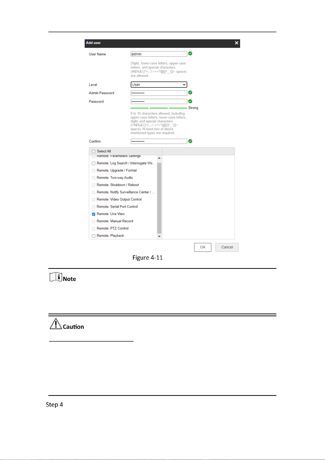
Input the Admin Password, User Name, select Level and input Password.
Mobile Network Camera • User Manual
29
Add a User
Up to 16 user accounts can be created.
Users of different levels own different default permissions. Operator and user are
selectable.
Strong Password recommended
We highly recommend you create a strong password of your own choosing (using a
minimum of 8 characters, including at least three of the following categories: upper
case letters, lower case letters, numbers, and special characters) in order to increase
the security of your product. And we recommend you reset your password regularly,
especially in the high security system, resetting the password monthly or weekly can
better protect your product.
You can check or uncheck the permissions for the new user.
Mobile Network Camera • User Manual
30
Click OK to finish the user addition.
Modify a User
Left-click to select the user from the list and click Modify.
Modify the User Name, Level and Password.
Strong Password recommended
We highly recommend you create a strong password of your own choosing (using a
minimum of 8 characters, including at least three of the following categories: upper
case letters, lower case letters, numbers, and special characters) in order to increase
the security of your product. And we recommend you reset your password regularly,
especially in the high security system, resetting the password monthly or weekly can
better protect your product.
You can check or uncheck the permissions.
Click OK to finish the user modification.
Deleting a User
1) Click to select the user you want to delete and click Delete.
2) Click OK on the pop-up dialogue box to confirm the deletion.
Operator/User
Operator or user can modify password. Old password is required for this action.
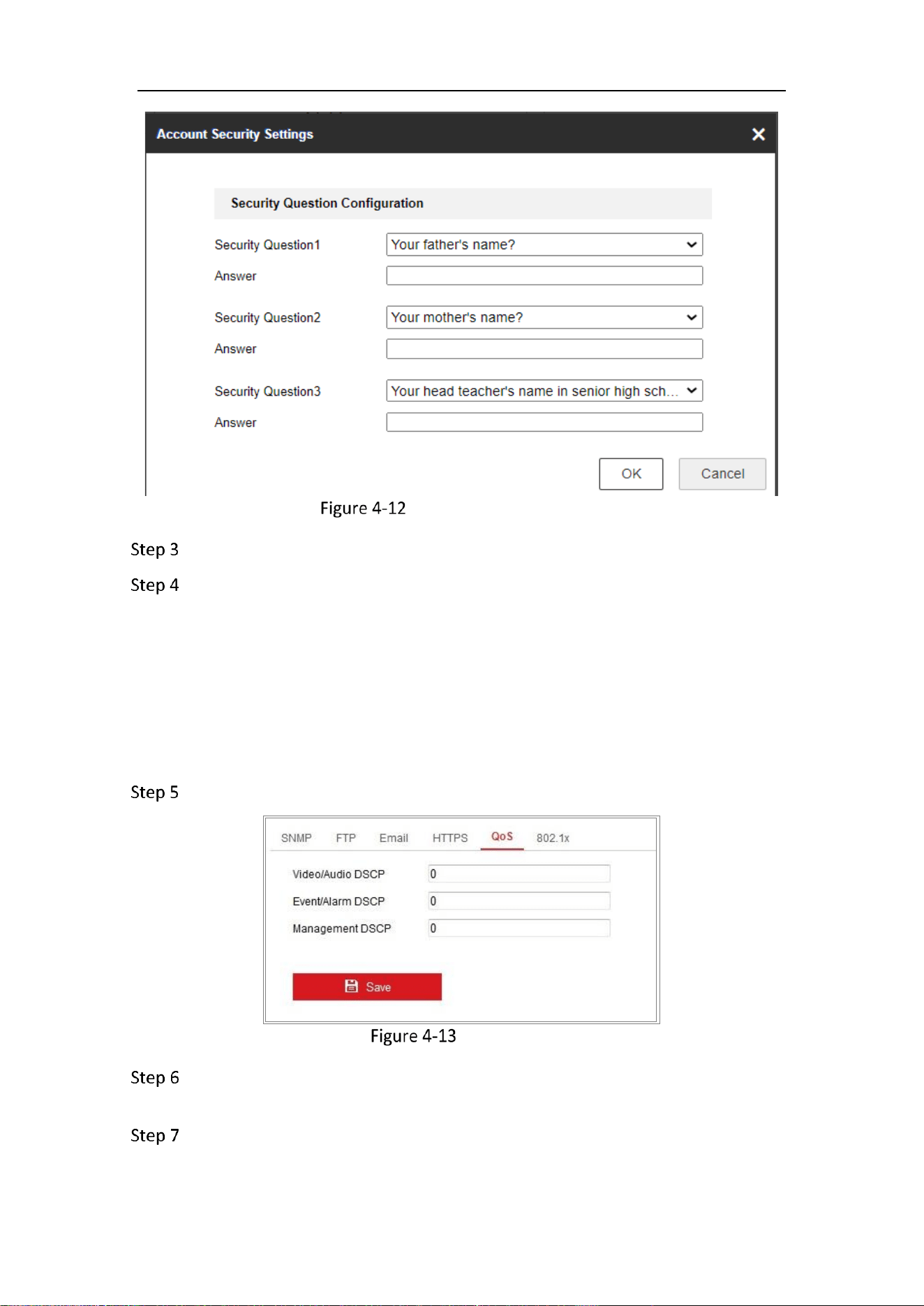
Purpose:
Security question is used to reset the admin password when admin user forgets the
password.
Set Security Questions
You can set the security questions during camera activation. Or you can set the
function at user management interface.
Security question setting is not cleared when you restore the camera (not to default).
Steps:
Go to Configuration > System > User Management.
Click Account Security Question.
Mobile Network Camera • User Manual
31
Account Security Question
Select questions and input answers.
Click OK to save the settings.
Reset Admin Password:
Before you start:
The PC used to reset password and the camera should belong to the same IP address
segment of the same LAN.
Steps:
Go to Configuration > Network > Advanced Settings > QoS
QoS Settings
Configure the QoS settings, including Video/Audio DSCP, Event/Alarm DSCP and
Management DSCP.
The valid value range of the DSCP is 0 to 63. The bigger the DSCP value is, the
higher the priority is.

Mobile Network Camera • User Manual
32
DSCP refers to the Differentiated Service Code Point; and the DSCP value is used in
the IP header to indicate the priority of the data.
Click Save to save the settings.
A reboot is required for the settings to take effect.
Purpose:
You can see the current users who are visiting the device through this interface. User
information, such as user name, level, IP address, and operation time, is displayed in
the User List.
Click Refresh to refresh the list.
View the Online Users

Mobile Network Camera • User Manual
33
Chapter 5 Network Settings
Purpose:
Follow the instructions in this chapter to configure the basic settings and advanced
settings.
Basic Settings
Purpose:
You can configure the parameters, including TCP/IP, DDNS, Port, and NAT, etc., by
following the instructions in this section.
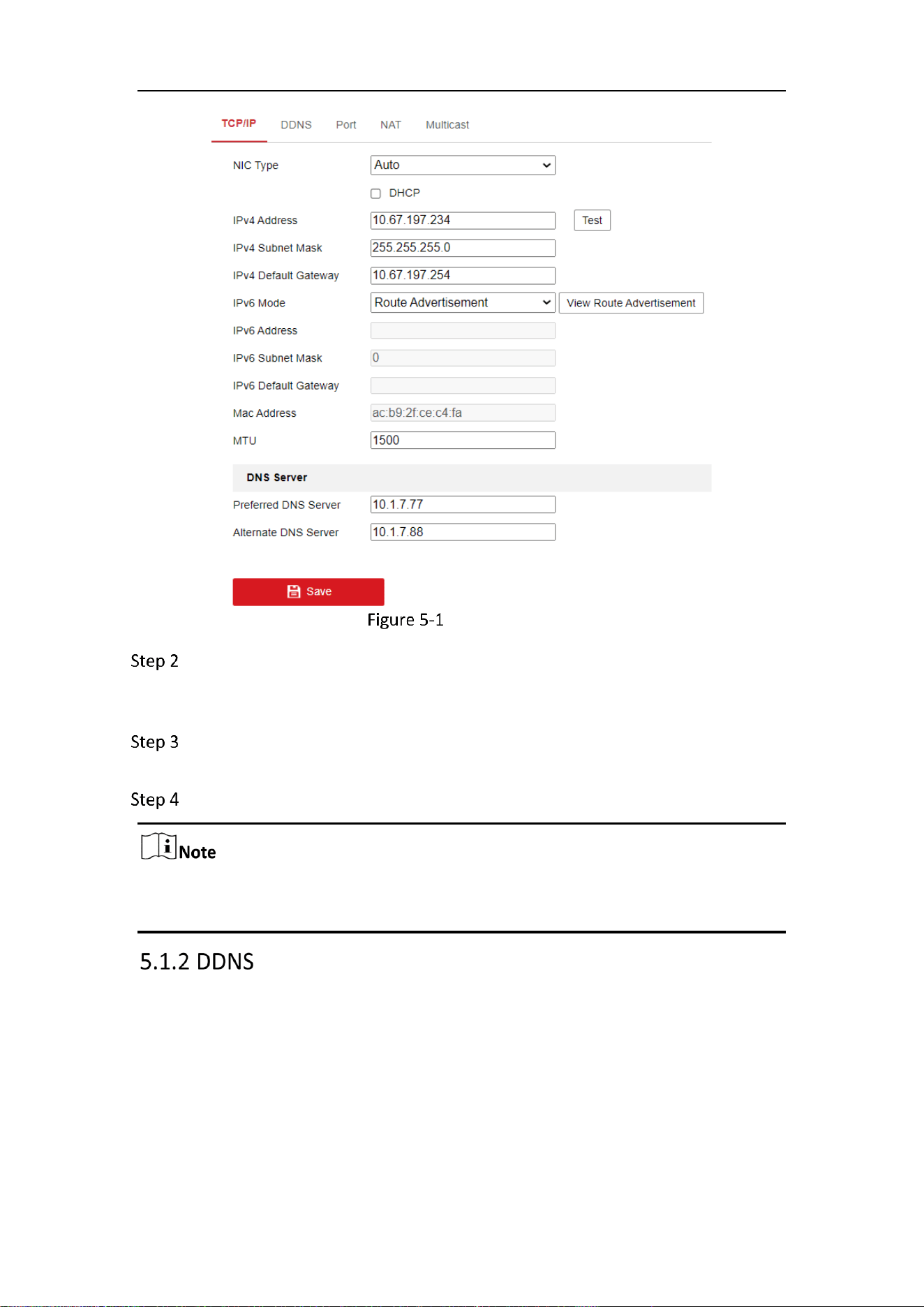
Purpose:
TCP/IP settings must be properly configured before you operate the camera over
network. The camera supports both the IPv4 and IPv6. Both versions can be configured
simultaneously without conflicting to each other, and at least one IP version should be
configured.
Go to Configuration > Network > Basic Settings > TCP/IP.
Mobile Network Camera • User Manual
34
TCP/IP Settings
Configure the basic network settings, including the NIC Type, IPv4 or IPv6
Address, IPv4 or IPv6 Subnet Mask, IPv4 or IPv6 Default Gateway, and MTU
settings.
Configure the DNS server. Input the preferred DNS server, and alternate DNS
server.
Click Save to save the above settings.
The valid value range of MTU is 1280 to 1500.
A reboot is required for the settings to take effect.
Purpose:
As most public internet users in use dynamic IP, Dynamic DNS (DDNS) for network
access is best for camera.
Before you start
:
Registration on the DDNS server is required before configuring the DDNS settings of
the camera.
Mobile Network Camera • User Manual
35
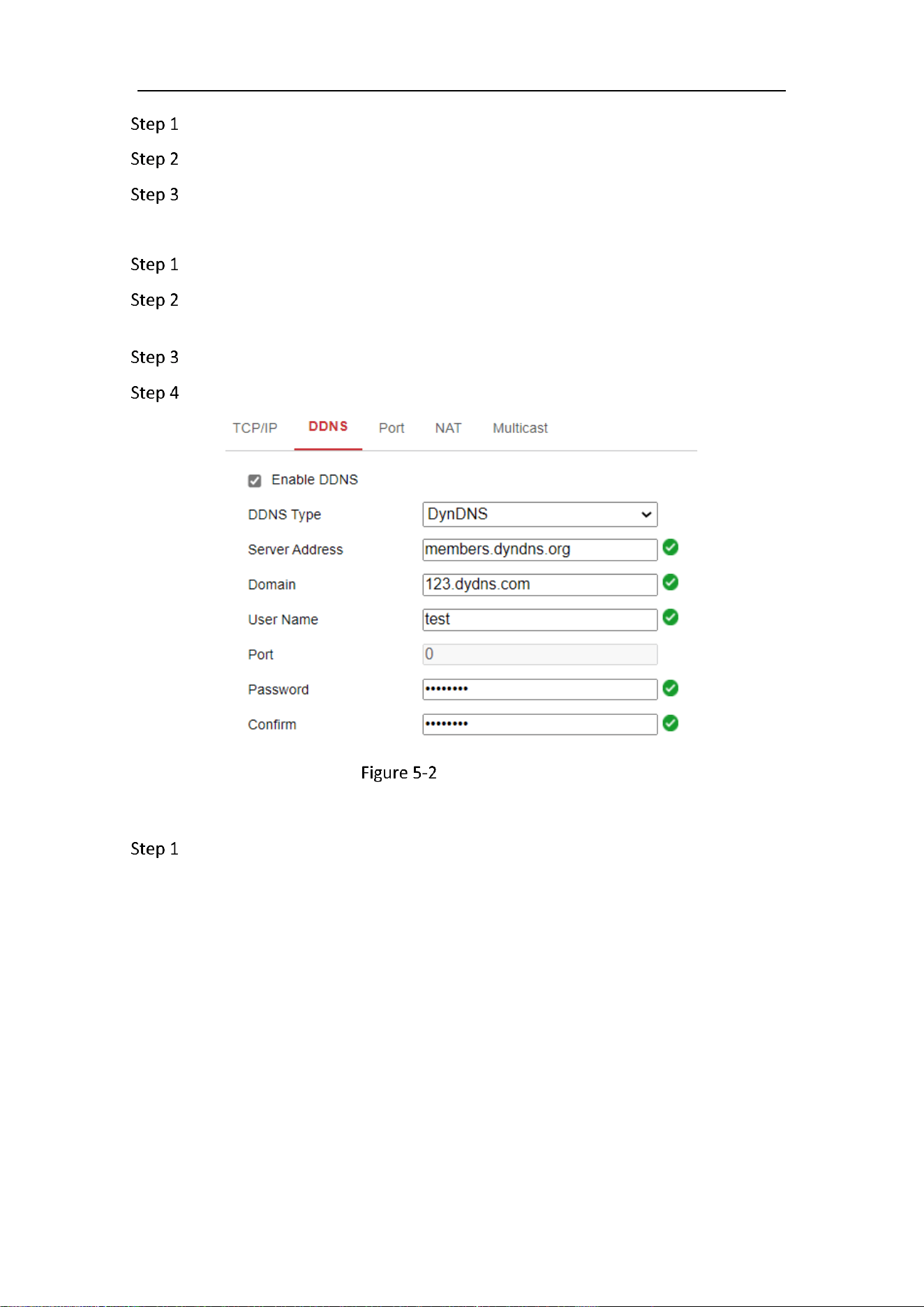
Go to Configuration > Network > Basic Settings > DDNS.
Check the Enable DDNS checkbox to enable this feature.
Select DDNS Type. Two DDNS types are selectable: DynDNS and NO-IP.
DynDNS:
Enter Server Address of DynDNS (e.g. members.dyndns.org).
In the Domain text field, enter the domain name obtained from the DynDNS
website.
Enter the User Name and Password registered on the DynDNS website.
Click Save to save the settings.
DynDNS Settings
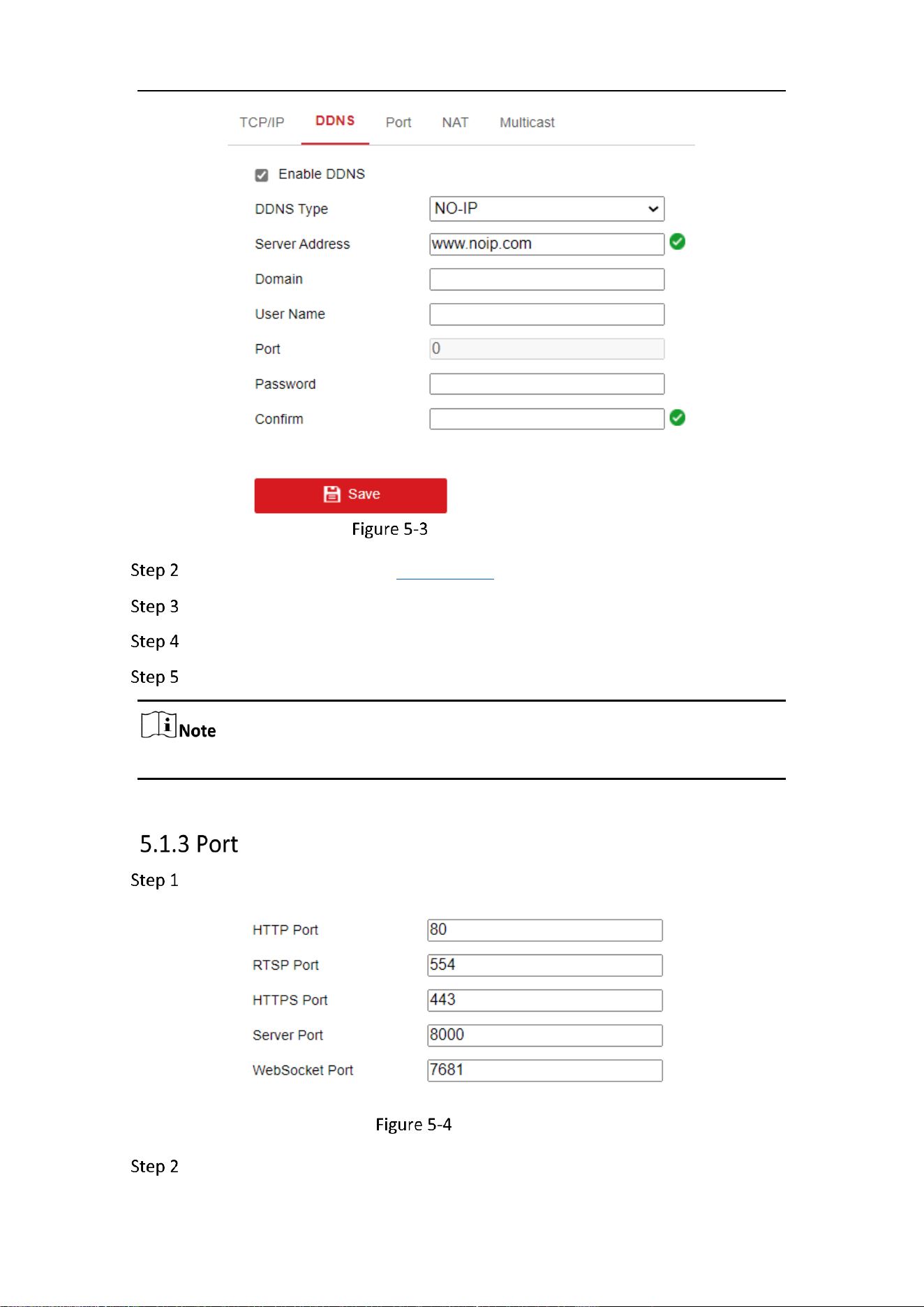
NO-IP:
Choose the DDNS Type as NO-IP.
Mobile Network Camera • User Manual
36
NO-IP DNS Settings
Enter the Server Address as www.noip.com
Enter the Domain name you registered.
Enter the User Name and Password.
Click Save and then you can view the camera with the domain name.
Reboot the device to make the settings take effect.
Go to Configuration > Network > Basic Settings > Port.
Port Settings
Set the ports of the camera.
Mobile Network Camera • User Manual
37
HTTP Port: The default port number is 80, and it can be changed to any port No. which
is not occupied.
RTSP Port: The default port number is 554 and it can be changed to any port No. ranges
from 1 to 65535.
HTTPS Port: The default port number is 443, and it can be changed to any port No.
which is not occupied.
Server Port: The default server port number is 8000, and it can be changed to any port
No. ranges from 2000 to 65535.
WebSocket Port: The default port number is 7681. It can be changed to any port No.
ranges from 1 to 65535.
The WebSocket protocol is used for plug-in free live view. For detailed information,
see 5.2.9 .
Click Save to save the settings.
A reboot is required for the settings to take effect.
Purpose:
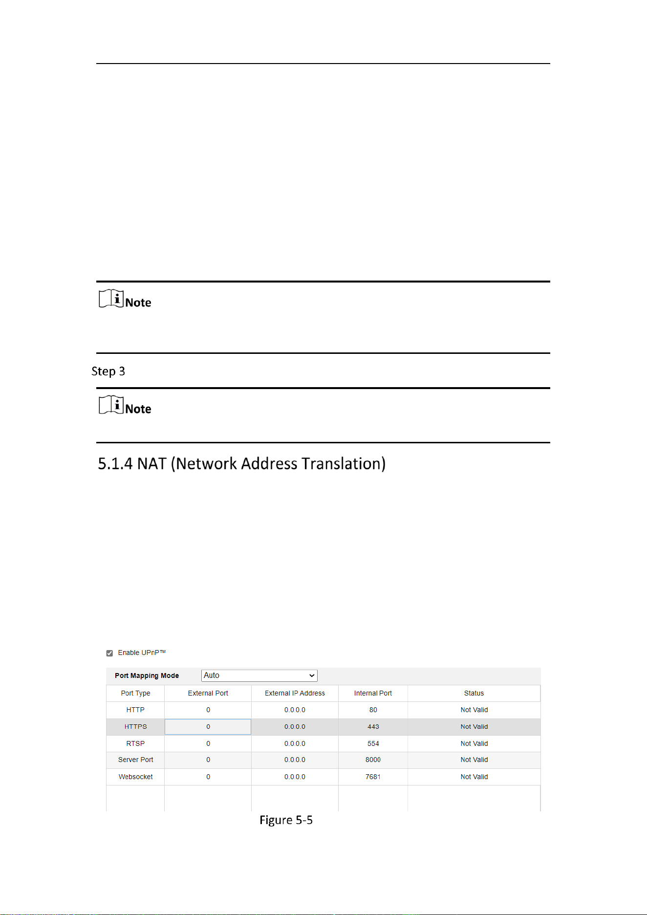
NAT interface allows you to configure the UPnP™ parameters.
Universal Plug and Play (UPnP™) is a networking architecture that provides
compatibility among networking equipment, software and other hardware devices.
The UPnP protocol allows devices to connect seamlessly and to simplify the
implementation of networks in the home and corporate environments.
With the function enabled, you don’t need to configure the port mapping for each
port, and the camera is connected to the Wide Area Network via the router.
UPnP Settings
Mobile Network Camera • User Manual
38
Go to Configuration > Network > Basic Settings > NAT.
Check the checkbox to enable the UPnP™ function.
Only when the UPnP™ function is enabled, ports of the camera are active.
Choose a friendly name for the camera, or you can use the default name.
Select the port mapping mode. Manual and Auto are selectable.
If you select Auto, you should enable UPnP™ function on the router.
If you select Manual, you can customize the value of the external port and
complete port mapping settings on router manually.
Click Save to save the settings.
The Multicast sends a stream to the multicast group address and allows multiple
clients to acquire the stream at the same time by requesting a copy from the multicast
group address. Before utilizing this function, you have to enable the Multicast function
of your router.
Go to Configuration > Network > Basic Settings > Multicast.
Configure the parameters for Multicast.
IP Address: The IP address of the multicast host.
The range for multicast IP address is 224.0.0.19~239.255.255.255
Stream Type
Choose the type of stream according to your needs.
For some models, the Third Stream is not enabled by default. Go to System >
Maintenance > System Service> Software to enable the function is required.
The main stream is usually for recording and live view with good bandwidth, and
the sub-stream can be used for live view when the bandwidth is limited.
You can customize the following parameters for the selected stream type.
Video Port and Audio Port: Port for Video and Audio.
Click Save.
Mobile Network Camera • User Manual
39
Advanced Settings
Purpose:
You can configure the parameters, including SNMP, FTP, Email, HTTPS, QoS, 802.1x,
etc., by following the instructions in this section.
Purpose:
You can set the SNMP function to get camera status, parameters and alarm related
information, and manage the camera remotely when it is connected to the network.
Before you start:
Before setting the SNMP, please download the SNMP software and manage to receive
the camera information via SNMP port. By setting the Trap Address, the camera can
send and download basic parameters from the SNMP management program.
The SNMP version you select should be the same as that of the SNMP software. And
you also need to use the different version according to the security level you
required. SNMP v1 provides no security and SNMP v2 requires password for access.
And SNMP v3 provides encryption and if you use the third version, HTTPS protocol
must be enabled.
STRONG PASSWORD RECOMMENDED
We highly recommend you create a strong password of your own choosing
(using a minimum of 8 characters, including at least three of the following
categories: upper case letters, lower case letters, numbers, and special
characters) in order to increase the security of your product. And we
recommend you reset your password regularly, especially in the high security
system, resetting the password monthly or weekly can better protect your
product.
Proper configuration of all passwords and other security settings is the
responsibility of the installer and/or end-user.
Steps:
Enter the SNMP Settings interface: Configuration > Network > Advanced
Settings > SNMP.
Mobile Network Camera • User Manual
40
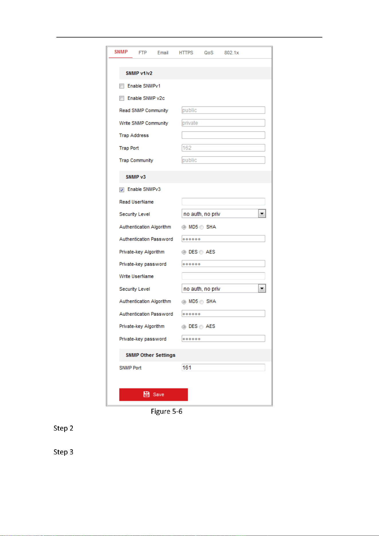
SNMP Settings
Check the checkbox of Enable SNMPv1, Enable SNMP v2c, Enable SNMPv3 to
enable the feature correspondingly.
Configure the SNMP settings.
Mobile Network Camera • User Manual
41
The settings of the SNMP software should be the same as the settings you configure
here.
Click Save to save and finish the settings.
A reboot is required for the settings to take effect.
To lower the risk of information leakage, you are suggested to enable SNMP v3
instead of SNMP v1 or v2.
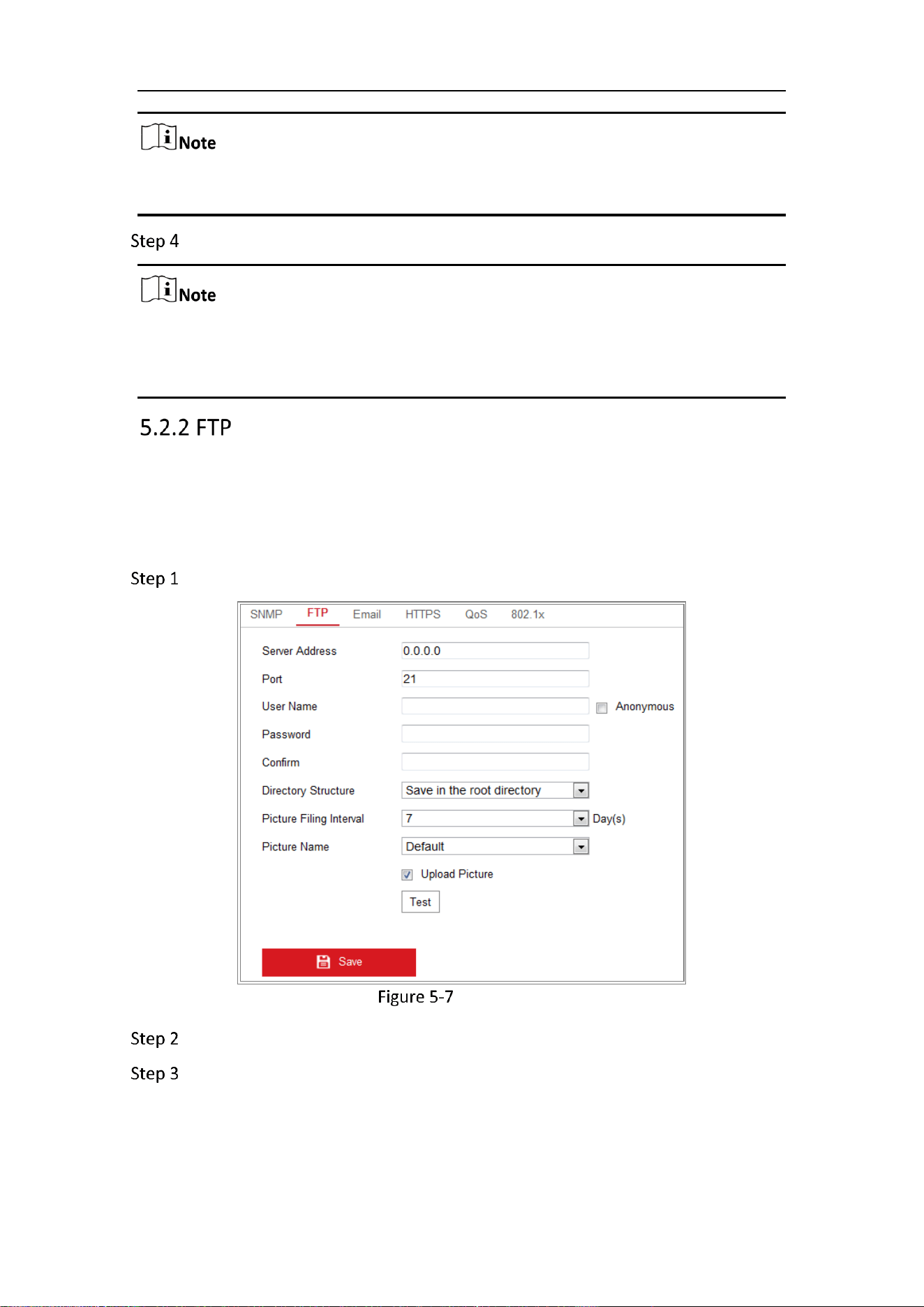
Purpose:
You can configure the FTP server related information to enable the uploading of the
captured pictures to the FTP server. The captured pictures can be triggered by events
or a timing snapshot task.
Go to Configuration > Network > Advanced Settings > FTP.
FTP Settings
Input the FTP address and port.
Configure the FTP settings; and the user name and password are required for
the FTP server login.

Mobile Network Camera • User Manual
42
STRONG PASSWORD RECOMMENDED
We highly recommend you create a strong password of your own choosing
(using a minimum of 8 characters, including at least three of the following
categories: upper case letters, lower case letters, numbers, and special
characters) in order to increase the security of your product. And we
recommend you reset your password regularly, especially in the high security
system, resetting the password monthly or weekly can better protect your
product.
Proper configuration of all passwords and other security settings is the
responsibility of the installer and/or end-user.
Set the directory structure and picture filing interval.
Directory: In the Directory Structure field, you can select the root directory,
parent directory and child directory. When the parent directory is selected, you have
the option to use the Device Name, Device Number or Device IP for the name of the
directory; and when the Child Directory is selected, you can use the Camera Name or
Camera No. as the name of the directory.
Picture Filing Interval: For better picture management, you can set the picture
filing interval from 1 day to 30 days. Pictures captured in the same time interval will
be saved in one folder named after the beginning date and ending date of the time
interval.
Picture Name: Set the naming rule for captured picture files. You can choose
Default in the drop-down list to use the default rule, that is, IP address channel
number capture time event type.jpg (e.g.,
10.11.37.189_01_20150917094425492_OBJECT_TRACKING.jpg).
Or you can customize it by adding a Custom Prefix to the default naming rule.
Check the Upload Picture checkbox to enable the function.
Upload Picture: To enable uploading the captured picture to the FTP server.
Anonymous Access to the FTP Server (in which case the user name and
password won’t be required.): Check the Anonymous checkbox to enable the
anonymous access to the FTP server.
The anonymous access function must be supported by the FTP server.
Click Save to save the settings.

Mobile Network Camera • User Manual
43
Purpose:
The system can be configured to send an Email notification to all designated receivers
if an alarm event is detected, e.g., motion detection event, video loss, video tampering,
etc.
Before you start:
Please configure the DNS Server settings under Configuration > Network > Basic
Settings > TCP/IP before using the Email function.
Go to Configuration > Network > Basic Settings > TCP/IP to set the IPv4 Address,
IPv4 Subnet Mask, IPv4 Default Gateway and the Preferred DNS Server.
Please refer to Section 7.1.1 Configure TCP/IP Settings for detailed information.
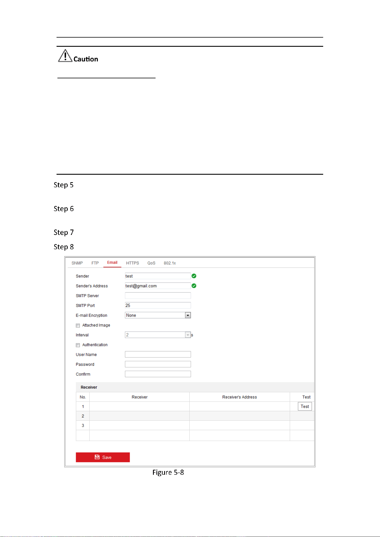
Go to Configuration > Network >Advanced Settings > Email.
Configure the following settings:
Sender: The name of the email sender.
Sender’s Address: The email address of the sender.
SMTP Server: IP address or host name (e.g., smtp.263xmail.com) of the SMTP
Server.
SMTP Port: The SMTP port. The default TCP/IP port for SMTP is 25 (not secured).
And the SSL SMTP port is 465.
Email Encryption: None and SSL are selectable. When you select SSL and disable
STARTTLS, e-mails will be sent after encrypted by SSL. The SMTP port should be set
as 465 for this encryption method. When you select SSL and enable STARTTLS, emails
will be sent after encrypted by STARTTLS, and the SMTP port should be set as 25.
If you want to use STARTTLS, make sure that the protocol is supported by your e-mail
server. If you check the Enable STARTTLS checkbox when the protocol is not
supported by your e-mail sever, your e-mail will not be encrypted.
Attached Image: Check the checkbox of Attached Image if you want to send
emails with attached alarm images.
Interval: The interval refers to the time between two actions of sending attached
pictures.
Authentication (optional): If your email server requires authentication, check
this checkbox to use authentication to log in to this server and input the login user
name and password.
Mobile Network Camera • User Manual
44
STRONG PASSWORD RECOMMENDED
We highly recommend you create a strong password of your own choosing
(using a minimum of 8 characters, including at least three of the following
categories: upper case letters, lower case letters, numbers, and special
characters) in order to increase the security of your product. And we
recommend you reset your password regularly, especially in the high security
system, resetting the password monthly or weekly can better protect your
product.
Proper configuration of all passwords and other security settings is the
responsibility of the installer and/or end-user.
Proper configuration of all passwords and other security settings is the
responsibility of the installer and/or end-user.
The Receiver table: Select the receiver to which the email is sent. Up to 3
receivers can be configured.
Receiver: The name of the user to be notified.
Receiver’s Address: The email address of user to be notified.
Email Settings
Mobile Network Camera • User Manual
45
Click Save to save the settings.
Purpose:
Platform access provides you an option to manage the devices via platform.
Go to Configuration > Network > Advanced Settings > Platform Access.
Check the checkbox of Enable to enable the platform access function of the
device.
Select the Platform Access Mode.
Hik-Connect is an application for mobile devices. With the App, you can view live
image of the camera, receive alarm notification and so on.
If you select Platform Access Mode as Hik-Connect,
1) Click and read "Terms of Service" and "Privacy Policy" in pop-up window.
2) Create a verification code or change the verification code for the camera.
The verification code is required when you add the camera to Hik-Connect app.
For more information about the Hik-Connect app, refer to Hik-Connect Mobile
Client User Manual.
You can use the default server address. Or you can check the Custom checkbox
on the right and input a desired server address.
Click Save to save the settings.
Purpose:
HTTPS provides authentication of the web site and its associated web server, which
protects against Man-in-the-middle attacks.
If HTTPS is enabled by default, the camera creates an unsigned certificate
automatically. When you visit the camera via HTTPS, the web browser will send a
notification about the certificate issue. Install a signed-certificate to the camera
to cancel the notification.
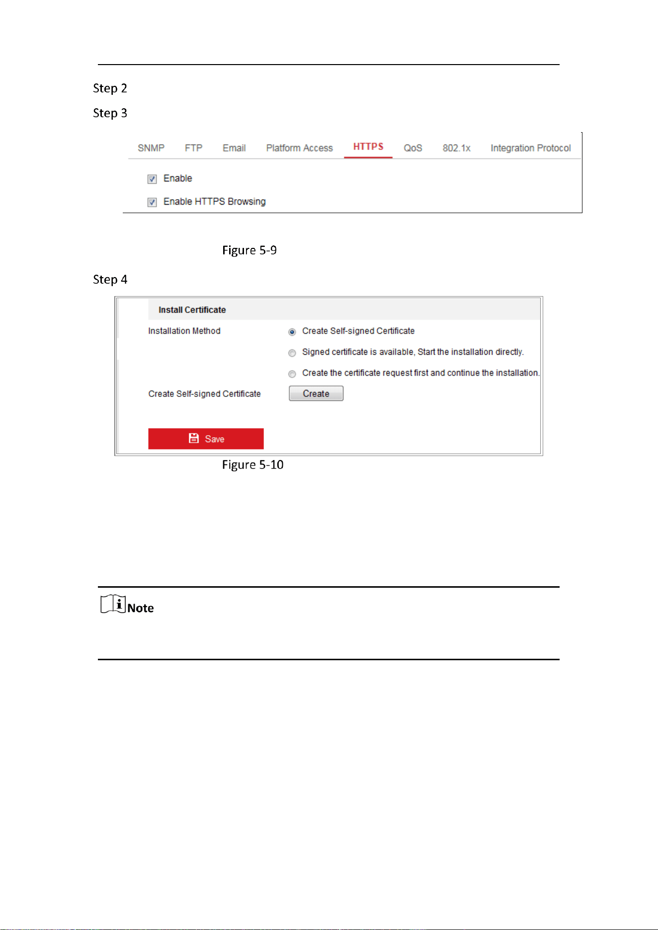
G to Configuration > Network > Advanced Settings > HTTPS.
Mobile Network Camera • User Manual
46
Check Enable to access the camera via HTTP or HTTPS protocol.
Check Enable HTTPS Browsing to access the camera only via HTTPS protocol.
HTTPS Configuration Interface
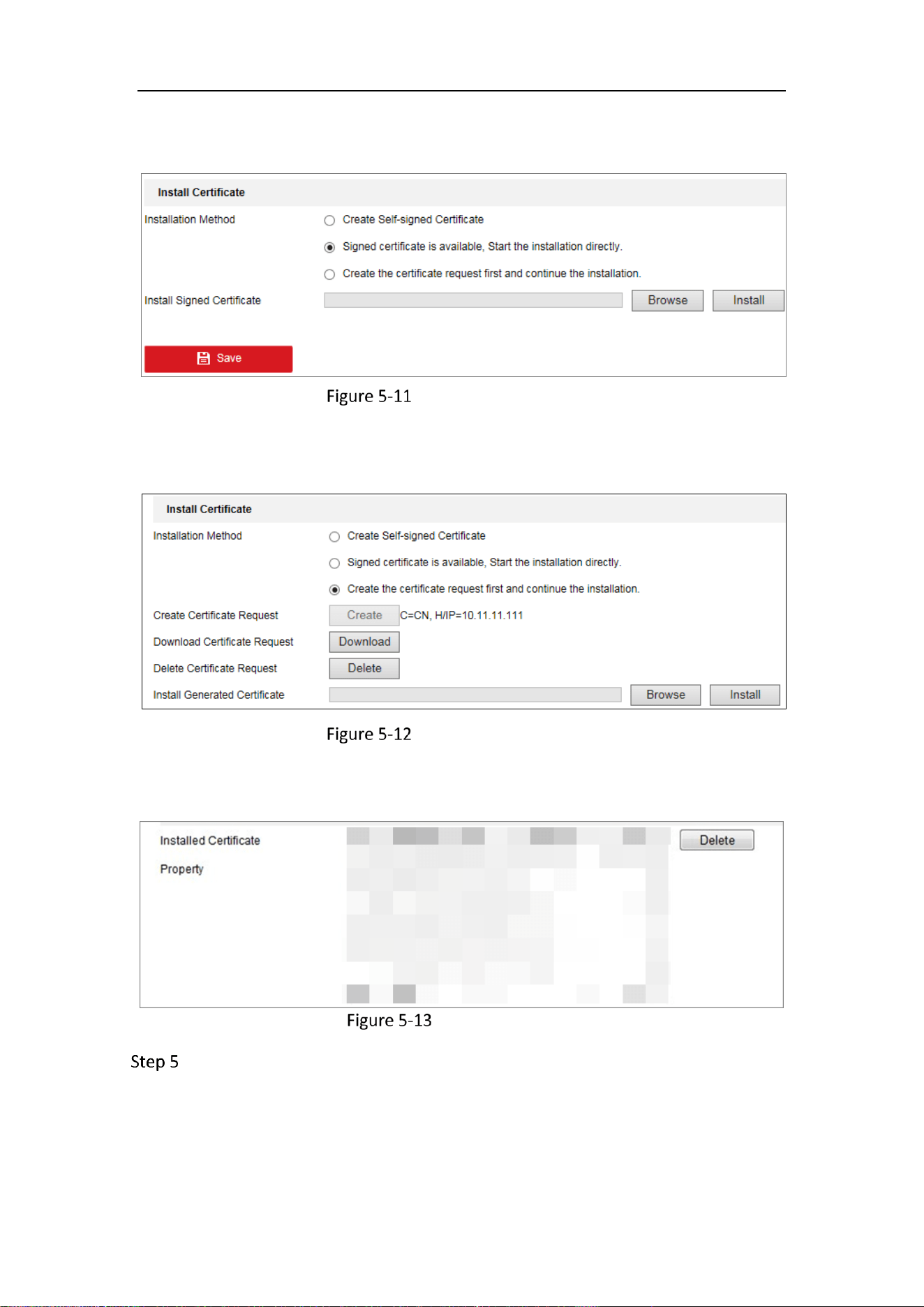
Create the self-signed certificate or authorized certificate.
Create Self-signed Certificate
Create the self-signed certificate
1) Select Create Self-signed Certificate as the Installation Method.
2) Click Create button to enter the creation interface.
3) Enter the country, host name/IP, validity and other information.
4) Click OK to save the settings.
If you already had a certificate installed, the Create Self-signed Certificate is grayed
out.
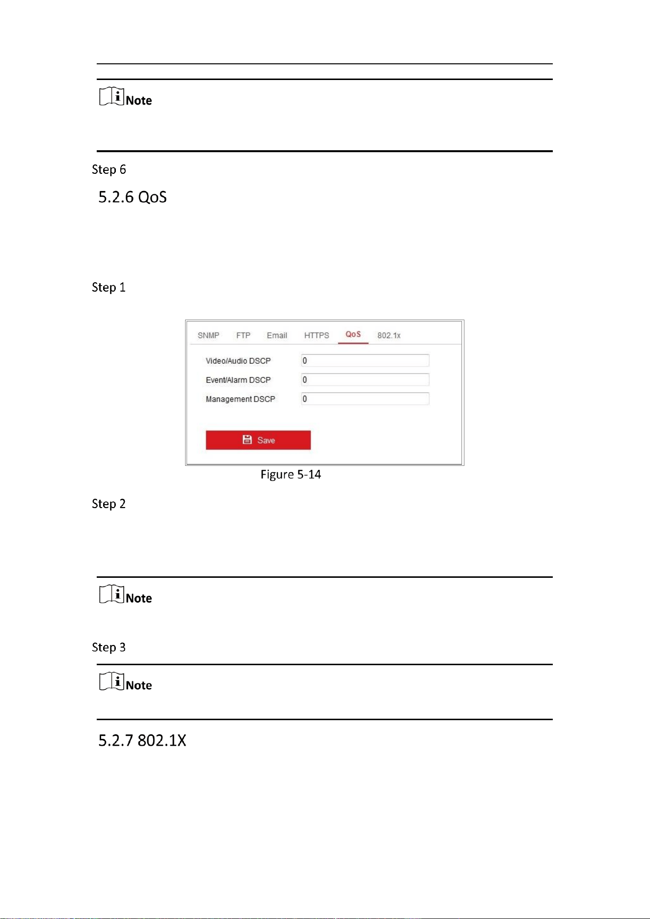
Create the request and import the authorized certificate
1) Select Create the certificate request first and continue the installation as
the Installation Method.
2) Click Create button to create the certificate request. Fill in the required
information in the popup window.
3) Click Download to download the certificate request and submit it to the
trusted certificate authority for signature.
4) After receiving the signed valid certificate, you can import the certificate in
two ways:
Mobile Network Camera • User Manual
47
− Select Signed certificate is available, Start the installation directly. Click
Browse and Install to import the certificate to the device.
Import the Certificate (1)
− Select Create the certificate request first and continue the installation.
Click Browse and Install to import the certificate to the device.
Import the Certificate (2)
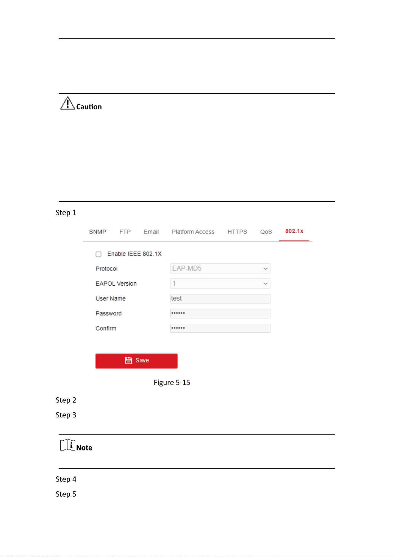
There will be the certificate information after your successfully creating and installing
the certificate.
Installed Certificate
Export and save the certificate for verification when adding the device to client
software.
Mobile Network Camera • User Manual
48
The exported certificate should be saved in the certificate folder of your client
software before adding the device to your PC client.
Click the Save button to save the settings.
Purpose:
QoS (Quality of Service) can help solve the network delay and network congestion by
configuring the priority of data sending.
Enter the QoS Settings interface: Configuration > Network > Advanced Settings >
QoS.
QoS Settings
Configure the QoS settings, including Video/Audio DSCP, Event/Alarm DSCP and
Management DSCP.
The valid value range of the DSCP is 0 to 63. The bigger the DSCP value is, the higher
the priority is.
DSCP refers to the Differentiated Service Code Point; and the DSCP
value is used in the IP header to indicate the priority of the data.
Click Save to save the settings.
A reboot is required for the settings to take effect.
Purpose:
The IEEE 802.1X standard is supported by the network cameras, and when the feature
is enabled, the camera data is secured and user authentication is needed when
connecting the camera to the network protected by the IEEE 802.1X.
Mobile Network Camera • User Manual
49
Before you start:
The authentication server must be configured. Please apply and register a user name
and password for 802.1X in the server.
For your privacy and to better protect your system against security risks, we
strongly recommend the use of strong passwords for all functions and network
devices. The password should be something of your own choosing (using a
minimum of 8 characters, including at least three of the following categories:
upper case letters, lower case letters, numbers and special characters) in order
to increase the security of your product.
Proper configuration of all passwords and other security settings is the
responsibility of the installer and/or end-user.
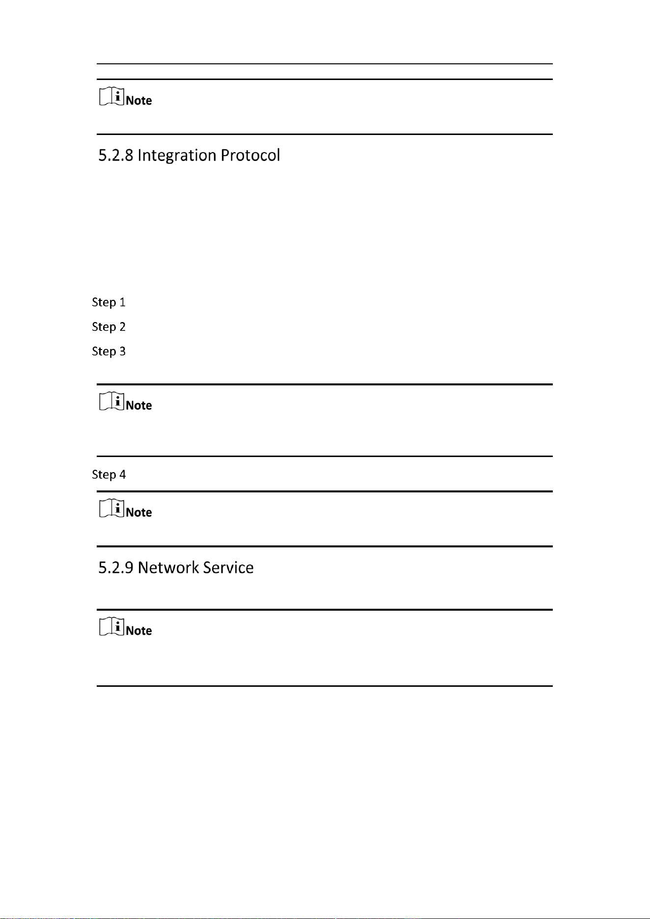
Go to Configuration > Network > Advanced Settings > 802.1X.
802.1X Settings
Check the Enable IEEE 802.1X checkbox to enable the feature.
Configure the 802.1X settings, including Protocol, EAPOL version, User Name,
Password and Confirm.
The EAPOL version must be identical with that of the router or the switch.
Enter the user name and password to access the server.
Click Save to finish the settings.
Mobile Network Camera • User Manual
50
A reboot is required for the settings to take effect.
Purpose:
If you need to access to the camera through the third party platform, you can enable
CGI function. And if you need to access to the device through ONVIF protocol, you can
configure ONVIF user in this interface. Refer to ONVIF standard for detailed
configuration rules.
ONVIF
Check the Enable ONVIF checkbox to enable the function.
Add ONVIF users. Up to 32 users are allowed.
Set the user name and password, and confirm the password. You can set the
user as media user, operator, and administrator.
ONVIF user account is different from the camera user account. You have set ONVIF
user account independently.
Save the settings.
User settings of ONVIF are cleared when you restore the camera.
You can control the ON/OFF status of certain protocol that the camera supports.
Keep unused function OFF for security concern.
Supported functions vary according to camera models.
WebSocket
WebSocket protocol should be enabled if you use Google Chrome 45 and its above
version or Mozilla Firefox 52 and its above version to visit your camera. Otherwise, live
view, image capture, and digital zoom function can not be used.
− If the camera uses HTTP, enable WebSocket.
SDK Service and Enhanced SDK Service
Mobile Network Camera • User Manual
51
If you want to add the device to the client software, you should enable SDK Service or
Enhanced SDK Service.
− SDK Service: SDK protocol is used.
− Enhanced SDK Service: SDK over TLS protocol is used. Communication
between the device and the client software is secured by using TLS
(Transport Layer Security) protocol.
TLS (Transport Layer Security)
The device offers TLS 1.1 and TLS 1.2. Enable one or more protocol versions according
to your need.
Purpose:
The HTTPS Listening supports uploading the alarm information to a target IP or domain,
one that supports http protocal transmission.
HTTPS Listening
Click Destination IP or Host Name, URL and Port to enter the target service (Up
to 3 services can be set).
Click Test to test the target service.
Click Default to reset the entered data.
Click Save.
Purpose:
Network Analysis .
Go to Configuration > Network > Advanced Settings > Network Analysis.
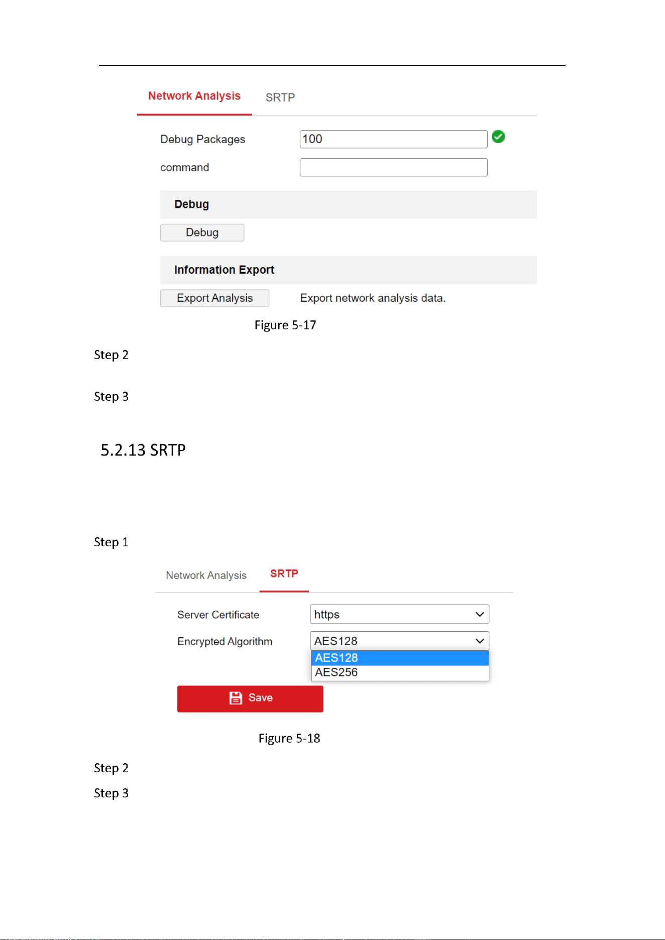
Mobile Network Camera • User Manual
52
Network Analysis
Enter the number of debug packages and command to test the network
connection.
Click Save.
Purpose:
Set the Sever Certificate and encrypted algorithm to prevent information leak in
remote control.
Go to Configuration > Network > Advanced Settings > SRTP.
HTTPS Listening
Select the Sever Certificate, currently only support https.
Select the encrypted algorithm as AES128 or AES256.
AES128 means that the length of the key is 128 bits;
AES256 means that the length of the key is 256 bits;
The longer the key is, the more secure. The defaut value algorithm is AES128.

Mobile Network Camera • User Manual
53
Click Save.
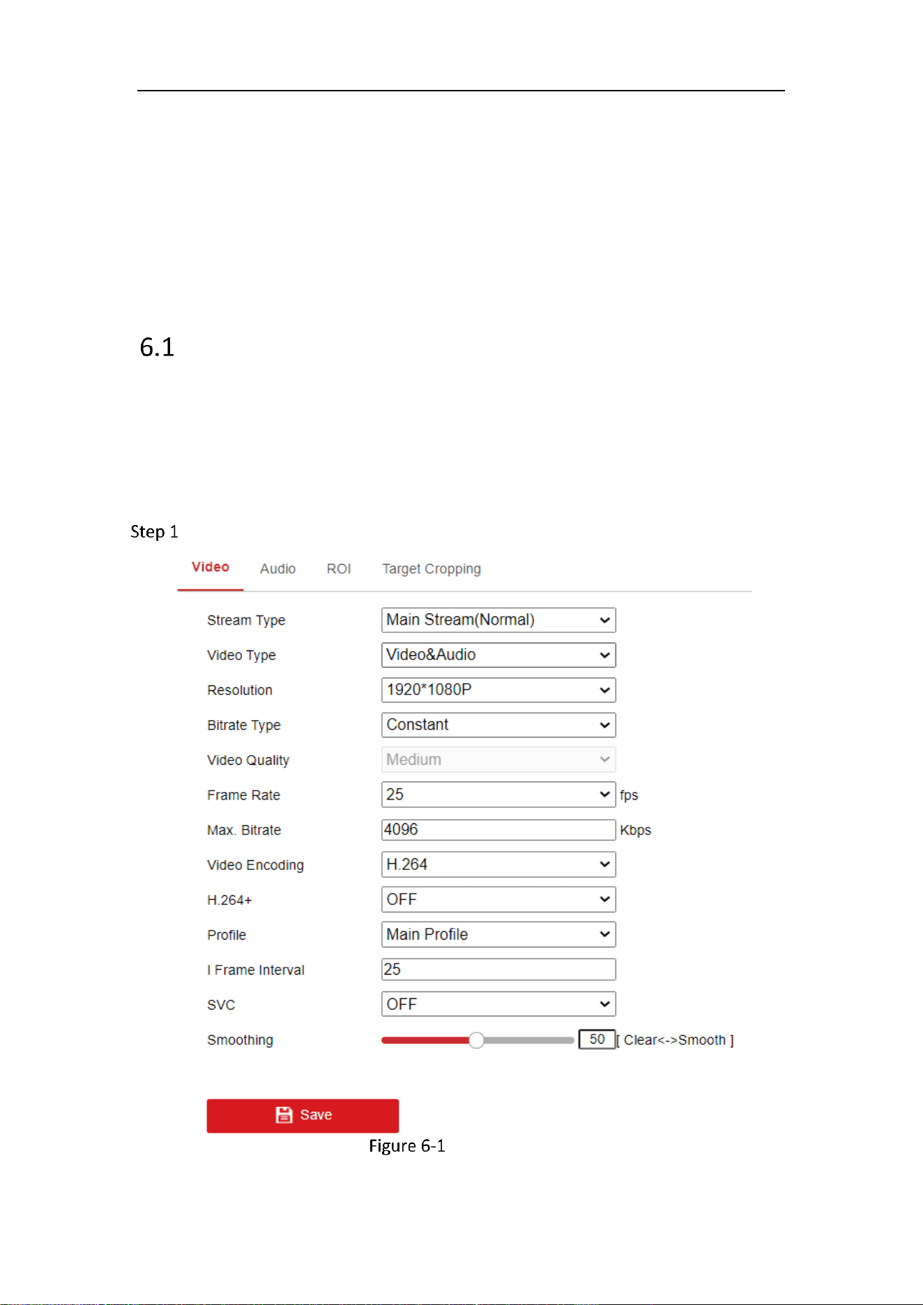
Mobile Network Camera • User Manual
54
Chapter 6 Video/Audio Settings
Purpose:
Follow the instructions below to configure the video setting, audio settings, ROI,
Display info. on Stream, etc.
Video
For certain camera models, you can configure parameters for available video streams,
for example, the main stream, the sub-stream, etc. And you can also customize
additional video streams for further needs.
On Video page, set-up available video streams.
On Custom Video page, add extra video streams
Go to Configuration > Video/Audio > Video
Video Settings

Mobile Network Camera • User Manual
55
Select the Stream Type.
Supported stream types are listed in the drop-down list.
For some models, the Third Stream is not enabled by default. Go to System >
Maintenance > System Service> Software to enable the function is required.
The main stream is usually for recording and live view with good bandwidth, and
the sub-stream can be used for live view when the bandwidth is limited.
You can customize the following parameters for the selected stream type.
Video Type:
Select the stream type to video stream, or video & audio composite stream. The audio
signal will be recorded only when the Video Type is Video & Audio.
Resolution:
Select the resolution of the video output.
Bitrate Type:
Select the bitrate type to constant or variable.
Video Quality:
When bitrate type is selected as Variable, 6 levels of video quality are selectable.
Frame Rate:
Set the frame rate. The frame rate is to describe the frequency at which the video
stream is updated and it is measured by frames per second (fps). A higher frame rate
is advantageous when there is movement in the video stream, as it maintains image
quality throughout.
Max. Bitrate:
Set the max. bitrate from 32 to 16384 Kbps. The higher value corresponds to the higher
video quality, but the better bandwidth is required.
The maximum limit of the max. bitrate value varies according to different camera
platforms. For certain cameras, the maximum limit is 8192 Kbps or 12288 Kbps.
Video Encoding:
The camera supports multiple video encodings types, such as H.264, H.265, and
MJPEG. Supported encoding type for different stream types may differ. H.265 is a new
encoding technology. Compared with H.264, it reduces the transmission bitrate under
the same resolution, frame rate and image quality.

Mobile Network Camera • User Manual
56
Selectable video encoding types may vary according to different camera modes.
H.264+ and H.265+:
− H.264+: If you set the main stream as the stream type, and H.264 as
the video encoding, you can see H.264+ available. H.264+ is an
improved compression coding technology based on H.264. By
enabling H.264+, users can estimate the HDD consumption by its
maximum average bitrate. Compared to H.264, H.264+ reduces
storage by up to 50% with the same maximum bitrate in most
scenes.
− H.265+: If you set the main stream as the stream type, and H.265 as
the video encoding, you can see H.265+ available. H.265+ is an
improved compression coding technology based on H.265. By
enabling H.265+, users can estimate the HDD consumption by its
maximum average bitrate. Compared to H.265, H.265+ reduces
storage by up to 50% with the same maximum bitrate in most
scenes.
You need to reboot the camera if you want to turn on or turn off the H.264+/H.265+.
If you switch from H.264+ to H.265+ directly, and vice versa, a reboot is not required
by the system.
Upgrade your video player to the latest version if live view or playback does not
work properly due to compatibility.
With H.264+/H.265+ enabled, the parameters such as profile, I frame interval,
video quality, and SVC are greyed out.
With H.264+/H.265+ enabled, some functions are not supported. For those
functions, corresponding interfaces will be hidden.
H.264+/H.265+ can spontaneously adjust the bitrate distribution according the
requirements of the actual scene in order to realize the set maximum average
bitrate in the long term. The camera needs at least 24 hours to adapt to a fixed
monitoring scene.
Max. Average Bitrate:
When you set a maximum bitrate, its corresponding recommended maximum average
bitrate will be shown in the Max. Average Bitrate box. You can also set the maximum
average bitrate manually from 32 Kbps to the value of the set maximum bitrate.
Profile:
When you select H.264 or H.265 as video encoding, you can set the profile. Selectable
profiles vary according to camera models.
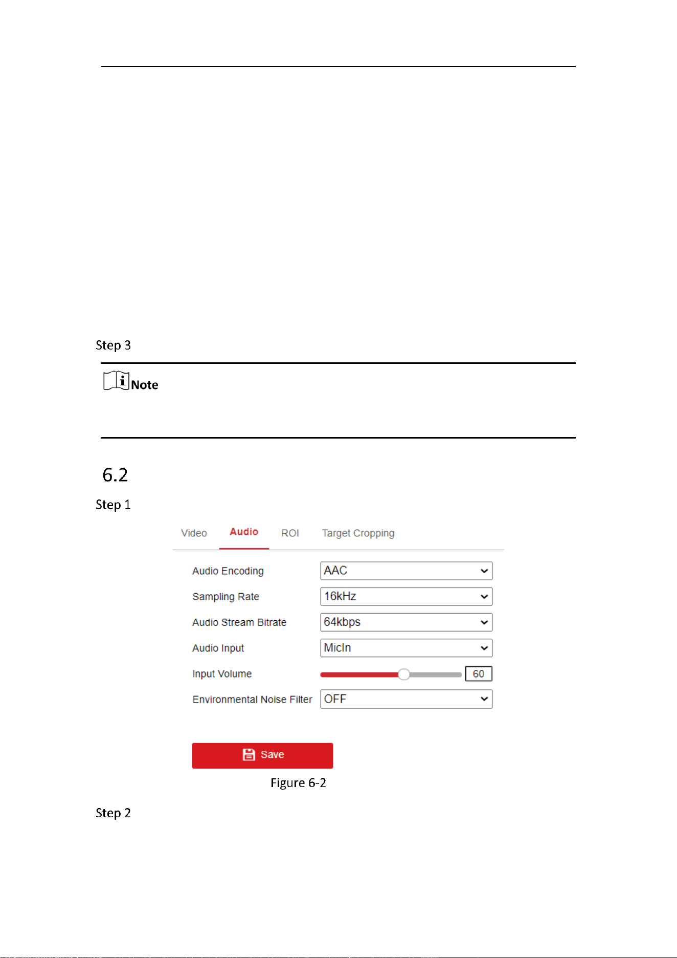
Mobile Network Camera • User Manual
57
I Frame Interval:
Set I Frame Interval from 1 to 400.
SVC:
Scalable Video Coding is an extension of the H.264/AVC and H.265 standard. Select
OFF/ON to disable/enable the SVC function. Select Auto and the device will
automatically extract frames from the original video when the network bandwidth is
insufficient.
Smoothing:
It refers to the smoothness of the stream. The higher value of the smoothing is, the
better fluency of the stream will be, though, the video quality may not be so
satisfactory. The lower value of the smoothing is, the higher quality of the stream will
be, though it may appear not fluent.
Click Save to save the settings.
The video parameters vary according to different camera models. Refer to the actual
display page for camera functions.
Audio
Go to Configuration > Video/Audio > Audio.
Audio Settings
Configure the following settings.

Mobile Network Camera • User Manual
58
Audio settings vary according to different camera models.
Audio Encoding: G.722.1, G.711 ulaw, G.711alaw, G.726 and PCM are selectable. For
PCM, the Sampling Rate can be set.
Audio Input: MicIn and LineIn are selectable for the connected microphone and pickup
respectively.
Input Volume: 0-100 adjustable.
Environmental Noise Filter: Set it as OFF or ON. When the function is enabled, the
noise in the environment can be filtered to some extent.
Click Save to save the settings.
ROI Encoding
Purpose:
ROI (Region of Interest) encoding helps to discriminate the ROI and background
information in video compression, which means, the technology assigns more
encoding resource to the region of interest, thus to increase the quality of the ROI
whereas the background information is less focused.
ROI function varies according to different camera models.
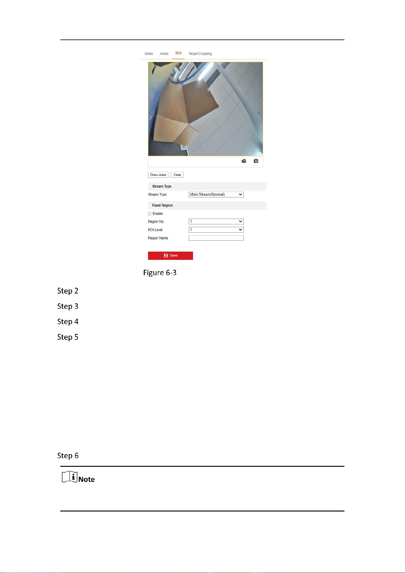
Mobile Network Camera • User Manual
59
Region of Interest Settings
Go to Configuration > Video/Audio > ROI.
Select the Stream Type for ROI encoding.
Check the checkbox of Enable under Fixed Region item.
Set Fixed Region for ROI.
1) Select the Region No. from the drop-down list.
2) Check the Enable checkbox to enable ROI function for the chosen region.
3) Click Drawing. Click and drag the mouse on the view screen to draw a red
rectangle as the ROI region. You can click Clear to cancel former drawing.
Click Stop Drawing when you finish.
4) Select the ROI level.
5) Enter a region name for the chosen region.
6) Click Save the save the settings of ROI settings for chosen fixed region.
7) Repeat steps (1) to (6) to setup other fixed regions.
Click Save to save the settings.
ROI level means the image quality enhancing level. The larger the value is, the better
the image quality would be.
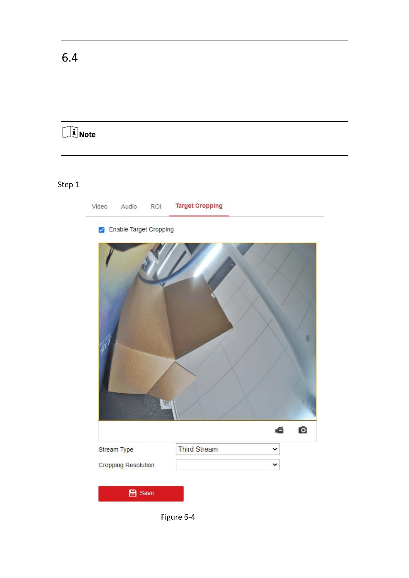
Mobile Network Camera • User Manual
60
Target Cropping
Purpose:
You can specify a target area on the live video, and then the specified video area can
be displayed via the third stream in certain resolution, providing more details of the
target area if needed.
Target cropping function varies according to different camera models.
Steps:
Enter the Target Cropping settings interface.
Target Cropping
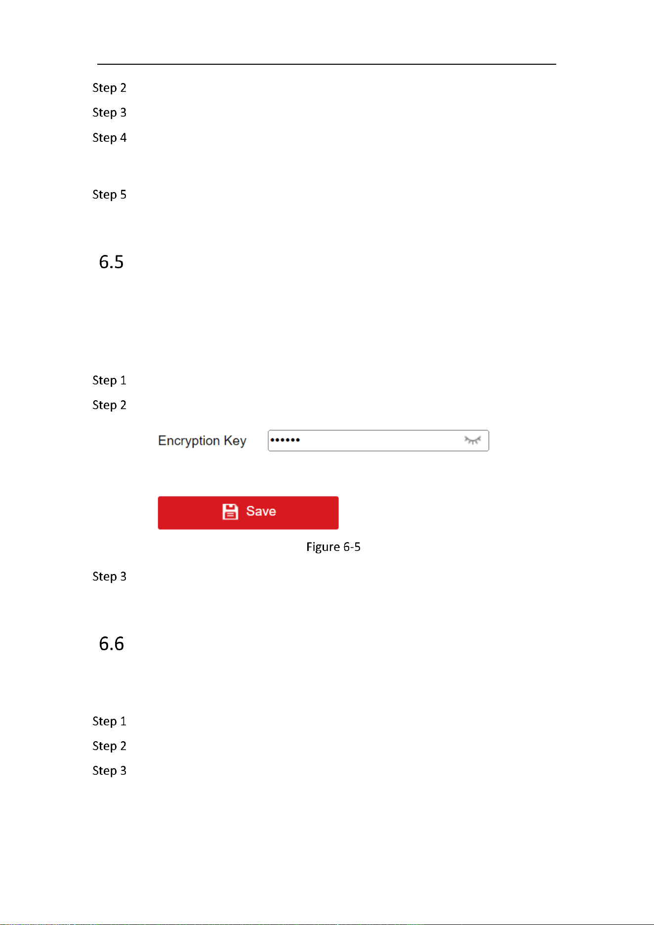
Mobile Network Camera • User Manual
61
Check Enable Target Cropping checkbox to enable the function.
Set Third Stream as the stream type.
Select the cropping resolution for the video display of target area. A red
rectangle is displayed on the live video to mark the target area, and you can
click-and-drag the rectangle to locate the target area as desired.
Click Save to save the settings.
Video Encryption
Purpose:
If you configured Video Encryption, then one can only preview the video with the
password you set.
Go to Configuration > Video/Audio > Video Encryption.
Enter the encryption key.
Encryption Key
Click Save to save the settings.
Privacy Mask
Purpose:
Privacy Mask will pixelate the faces that appear in the video.
Go to Configuration > Video/Audio > Privacy Mask.
Check Enable Privacy Masks.
Click Save to save the settings.
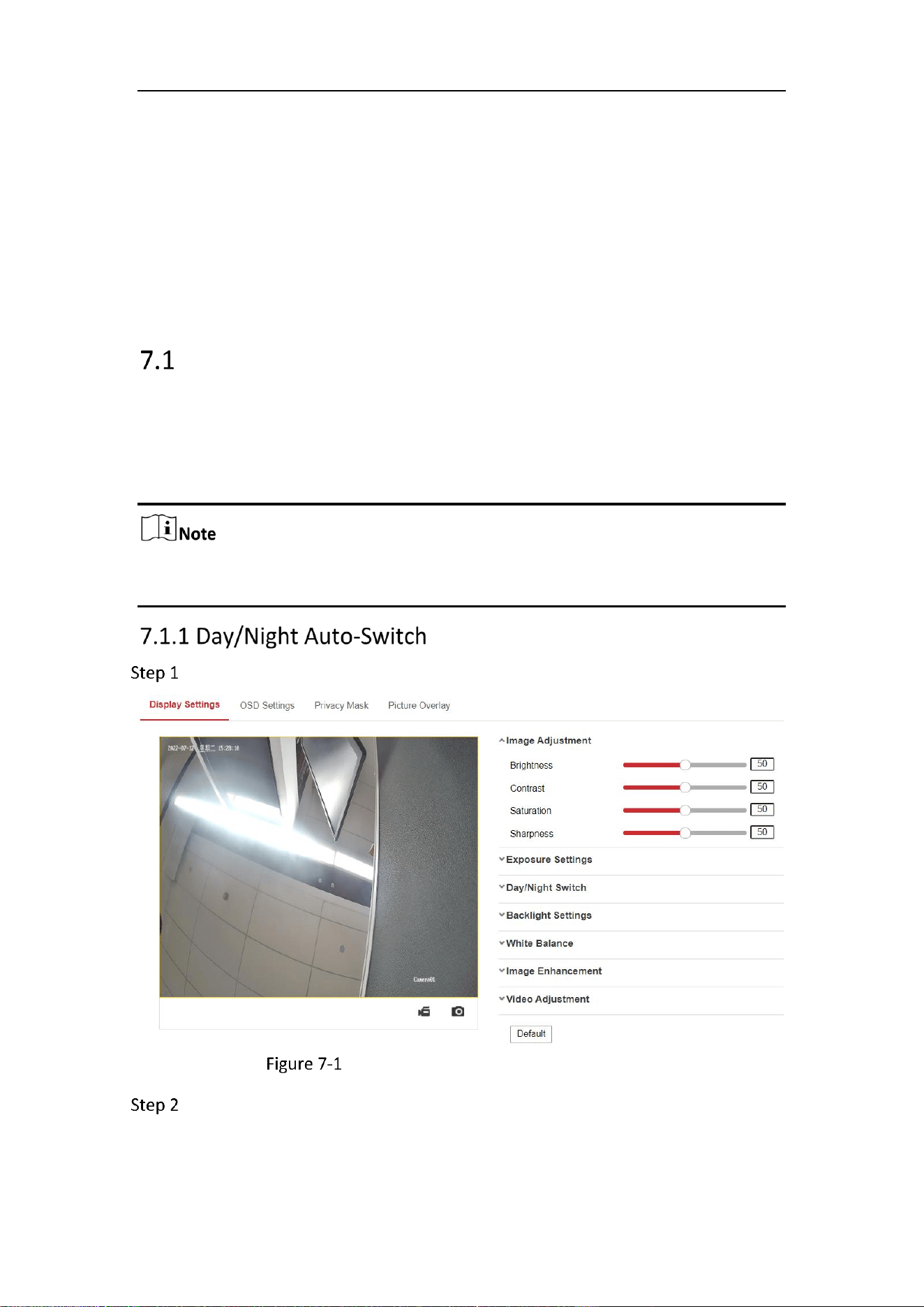
Mobile Network Camera • User Manual
62
Chapter 7 Image Settings
Purpose:
Follow the instructions in this chapter to configure the image parameters, including
display settings, OSD settings, privacy mask, and picture overlay.
Display Settings
Purpose:
Configure the image adjustment, exposure settings, day/night switch, backlight
settings, white balance, image enhancement, video adjustment, and other parameters
in display settings.
The display parameters vary according to the different camera models. Please refer
to the actual interface for details.
Go to Configuration > Image > Display Settings.
Display Settings of Day/Night Auto-Switch
Set the image parameters of the camera.
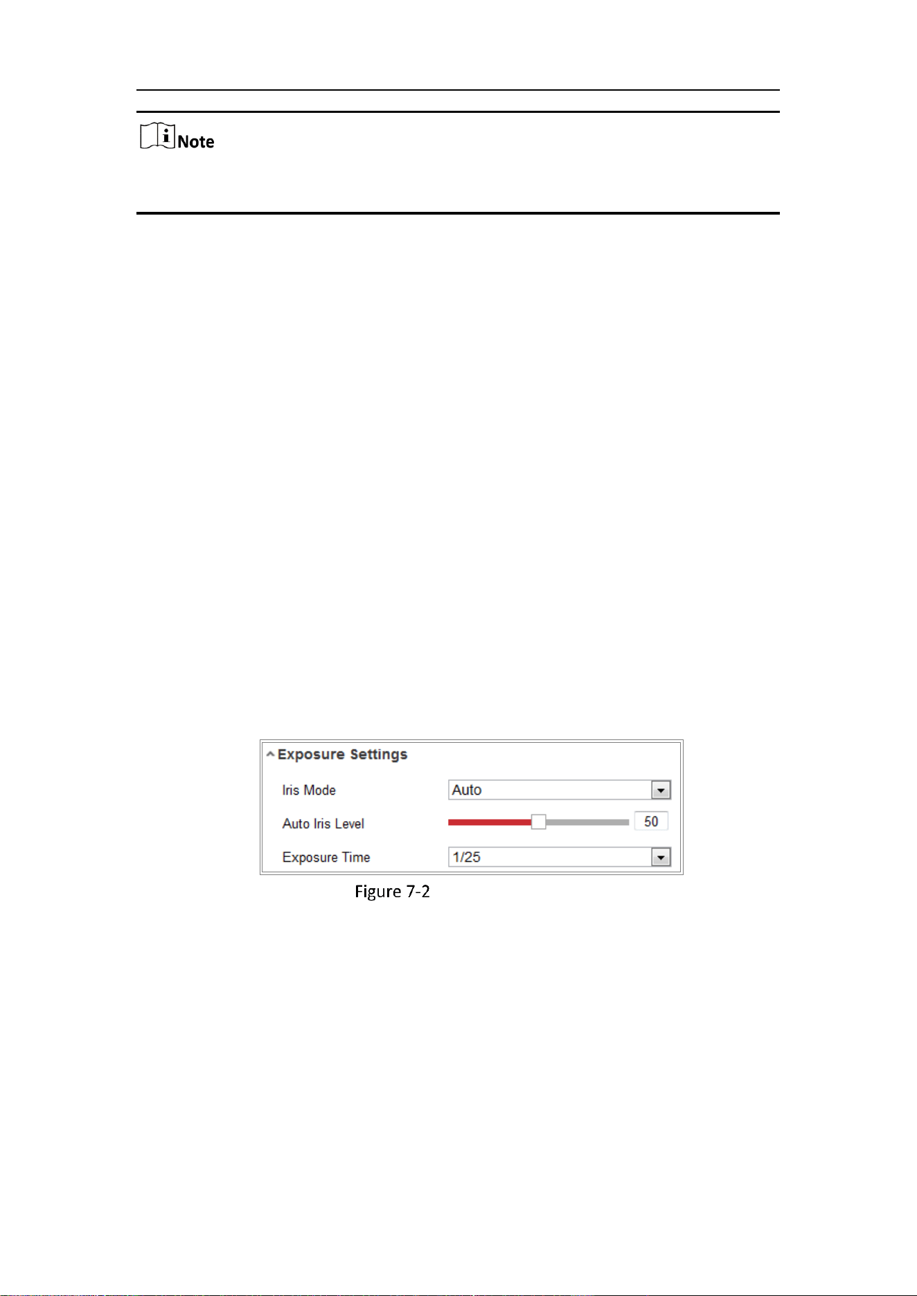
Mobile Network Camera • User Manual
63
In order to guarantee the image quality in different illumination, it provides two sets
of parameters for users to configure.
Image Adjustment
− Brightness describes how bright the image is, which ranges from 1 to
100.
− Contrast describes the contrast of the image, which ranges from 1 to
100.
− Saturation describes how colorful of the image is, which ranges from 1
to 100.
− Sharpness describes the edge contrast of the image, which ranges
from 1 to 100.
Exposure Settings
− If the camera is equipped with the fixed lens, only Manual is
selectable, and the iris mode is not configurable.
− If Auto is selected, you can set the auto iris level from 0 to 100.
− The Exposure Time refers to the electronic shutter time, which ranges
from 1 to 1/100, 000 s. Adjust it according to the actual luminance
condition.
− Gain of image can also be manually configured from 0 to 100. The
bigger the value is, the brighter would the image be, and the noise
would also be amplified to a larger extent.
Exposure Settings
Focus
For camera support motor-driven lens, you can set the focus mode as Auto,
Manual or Semi-auto.
− Auto: Camera focus is adjusted automatically according to the actual
monitoring scenario.
− Manual: You can control the lens by adjusting the zoom, focus, lens
initialization, and auxiliary focus manually.
− Semi-Auto: Camera will focus automatically when you adjust the zoom
parameters.
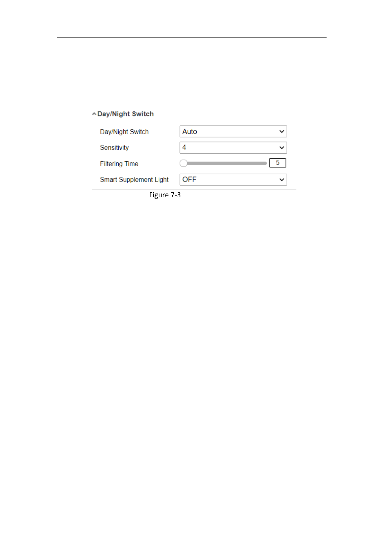
Mobile Network Camera • User Manual
64
Day/Night Switch
Select the Day/Night Switch mode according to different monitoring demand.
Day, Night, Auto, Scheduled-Switch, and Triggered by alarm input are selectable
for day/night switch.
Day/Night Switch
− Day: the camera stays at day mode.
− Night: the camera stays at night mode.
− Auto: the camera switches between the day mode and the night mode
according to the illumination automatically. The sensitivity ranges
from 0 to 7, the higher the value is, the easier the mode switches.
The Filtering Time refers to the interval time between the day/night
switch. You can set it from 5 s to 120 s.
− Scheduled-Switch: Set the start time and the end time to define the
duration for day/night mode.
− Triggered by alarm input: The switch is triggered by alarm input. You
can set the triggered mode to day or night.
− Smart Supplement Light: Set the supplement light as ON, and Auto
and Manual are selectable for light mode.
− Select Auto, and the supplement light changes according to the actual
luminance. E.g., if the current scene is bright enough, then the
supplement light adjusts itself to lower power; and if the scene is not
bright enough, the light adjusts itself to higher power.
− Select Manual, and you can adjust the supplement by adjusting the
distance. E.g., if the object is near the camera, the device adjusts the
supplement light to lower power, and the light is in higher power if
the object is far away.
Backlight Settings
− BLC Area: If you focus on an object against strong backlight, the object
will be too dark to be seen clearly. BLC compensates light to the
object in the front to make it clear. OFF, Up, Down, Left, Right,
Center, Auto, and Custom are selectable.
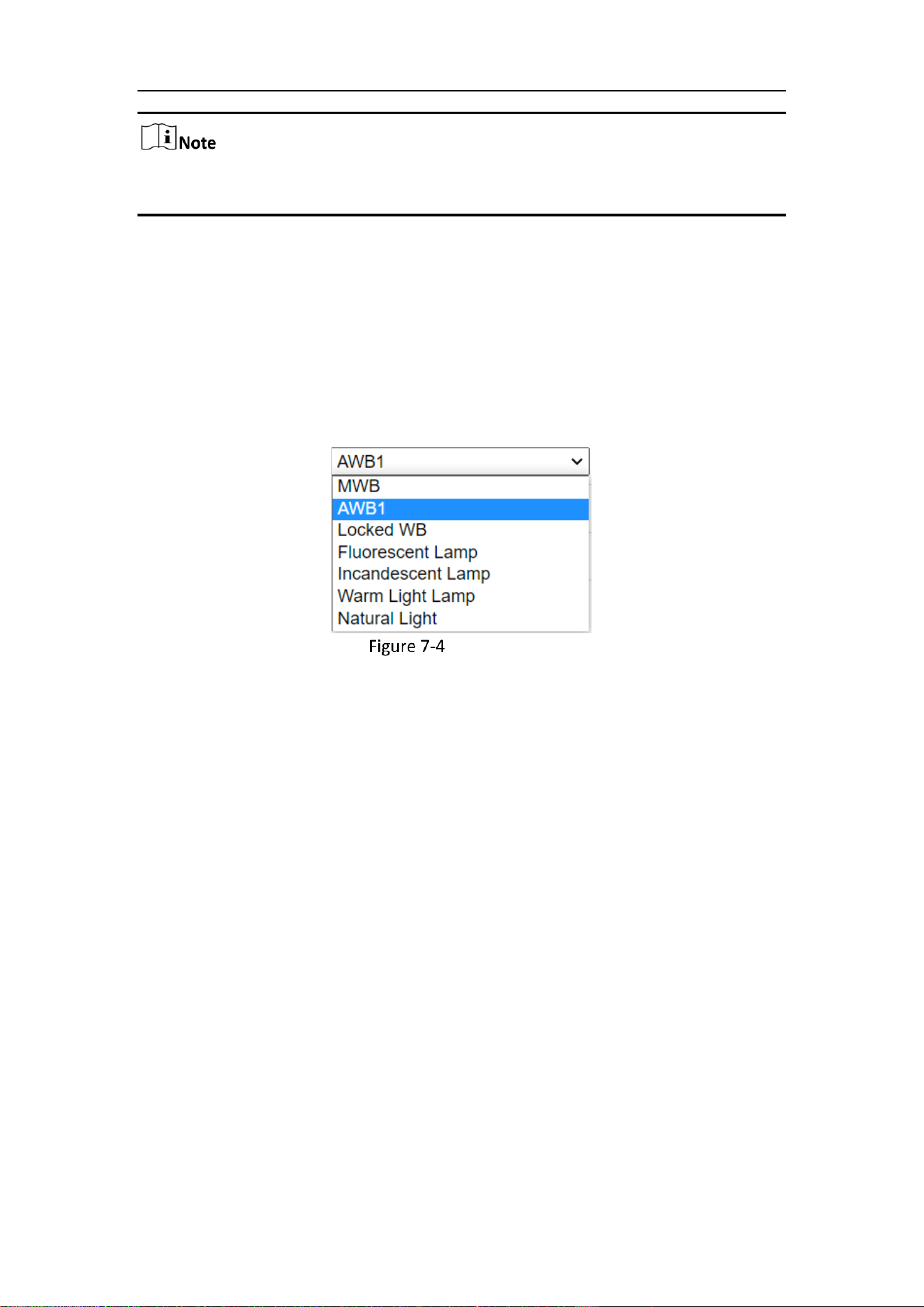
Mobile Network Camera • User Manual
65
If BLC mode is set as Custom, you can draw a red rectangle on the live view image as
the BLC area.
− WDR: Wide Dynamic Range can be used when there is a high contrast
of the bright area and the dark area of the scene.
− HLC: High Light Compression function can be used when there are
strong lights in the scene affecting the image quality.
White Balance
White balance is the white rendition function of the camera used to adjust the
color temperature according to the environment.
White Balance
Image Enhancement
− Digital Noise Reduction: DNR reduces the noise in the video stream.
OFF, Normal and Expert are selectable. Set the DNR level from 0 to
100 in Normal Mode. Set the DNR level from both space DNR level
[0-100] and time DNR level [0-100] in Expert Mode.
− Defog Mode: You can enable the defog function when the
environment is foggy and the image is misty. It enhances the subtle
details so that the image appears clearer.
− EIS (Electrical Image Stabilizer): EIS reduces the effects of vibration in a
video.
− Grey Scale: You can choose the range of the grey scale as [0-255] or
[16-235].
Video Adjustment
− Mirror: It mirrors the image so you can see it inversed. Left/Right,
Up/Down, Center, and OFF are selectable.
− Rotate: To make a complete use of the 16:9 aspect ratio, you can
enable the rotate function when you use the camera in a narrow
view scene.
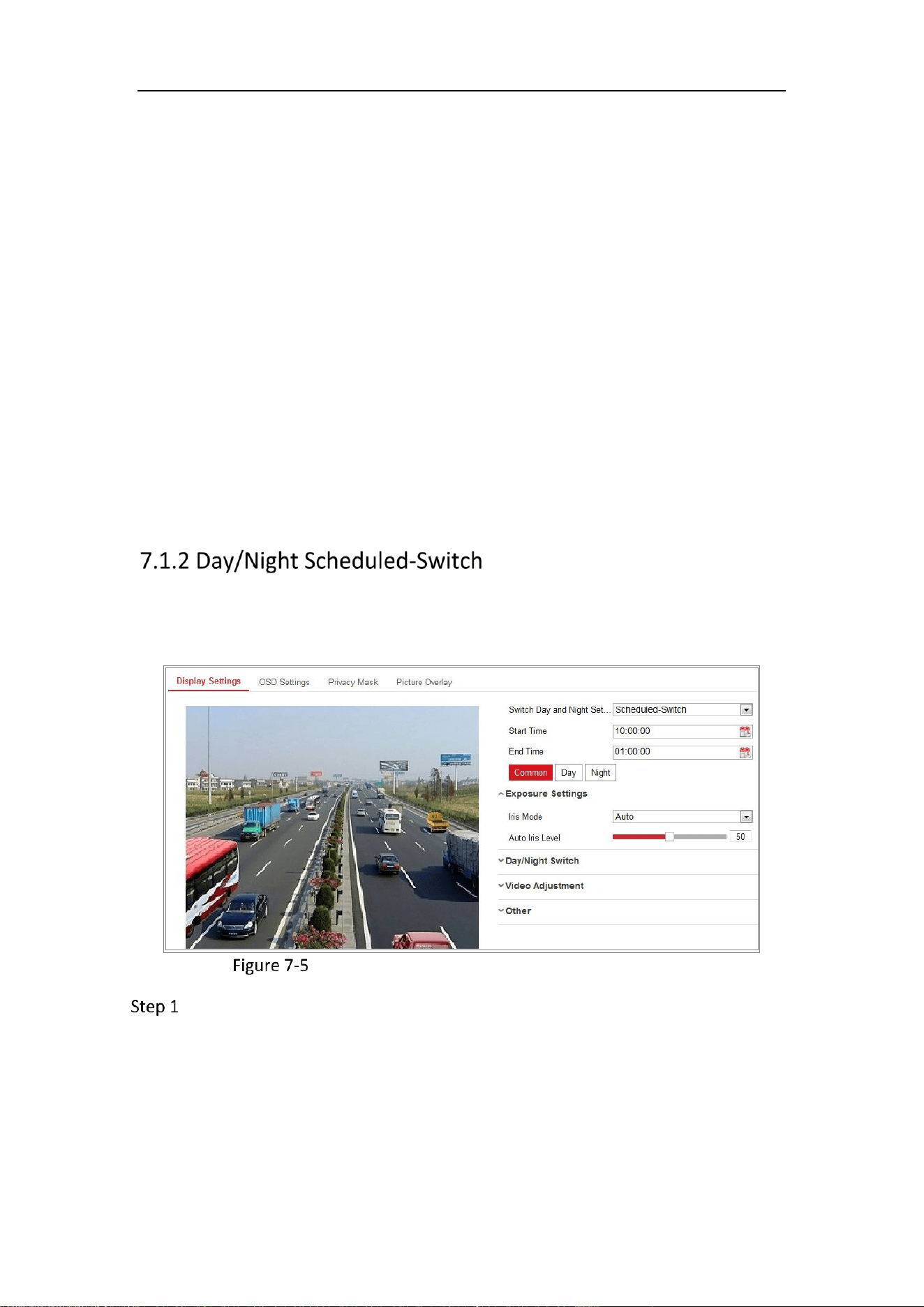
Mobile Network Camera • User Manual
66
− When installing, turn the camera to the 90 degrees or rotate the 3-axis
lens to 90 degrees, and set the rotate mode as on, you will get a
normal view of the scene with 9:16 aspect ratio to ignore the
needless information such as the wall, and get more meaningful
information of the scene.
− Scene Mode: Choose the scene as indoor or outdoor according to the
real environment.
− Video Standard: 50 Hz and 60 Hz are selectable. Choose according to
the different video standards; normally 50 Hz for PAL standard and
60 Hz for NTSC standard.
− Lens Distortion Correction: For cameras equipped with motor-driven
lens, image may appear distorted to some extent. Turn on this
function to correct the distortion.
Others
Some camera models support CVBS, SDI, or HDMI output. Set the local output ON or
OFF according to the actual device.
Day/Night scheduled-switch configuration interface enables you to set the camera
parameters for day and night separately, guaranteeing the image quality in different
illumination.
Day/Night Scheduled-Switch Configuration Interface
Click the calendar icon to select the start time and the end time of the switch.

Mobile Network Camera • User Manual
67
The start time and end time refer to the valid time for day mode.
The time period can start and end on two days in a row. For example, if you set
start time as 10:00 and end time as 1:00, the day mode will be activated at 10
o'clock in the morning and stopped at 1 o'clock early in the next morning.
Click Common tab to configure the common parameters applicable to the day
mode and night mode.
For the detailed information of each parameter, please refer to Section 9.1.1
Day/Night Auto-Switch.
Click Day tab to configure the parameters applicable for day mode.
Click Night tab to configure the parameters applicable for night mode.
The settings saved automatically if any parameter is changed.
OSD Settings
Purpose:
You can customize the camera name, time/date format, display mode, and OSD size
displayed on the live view.
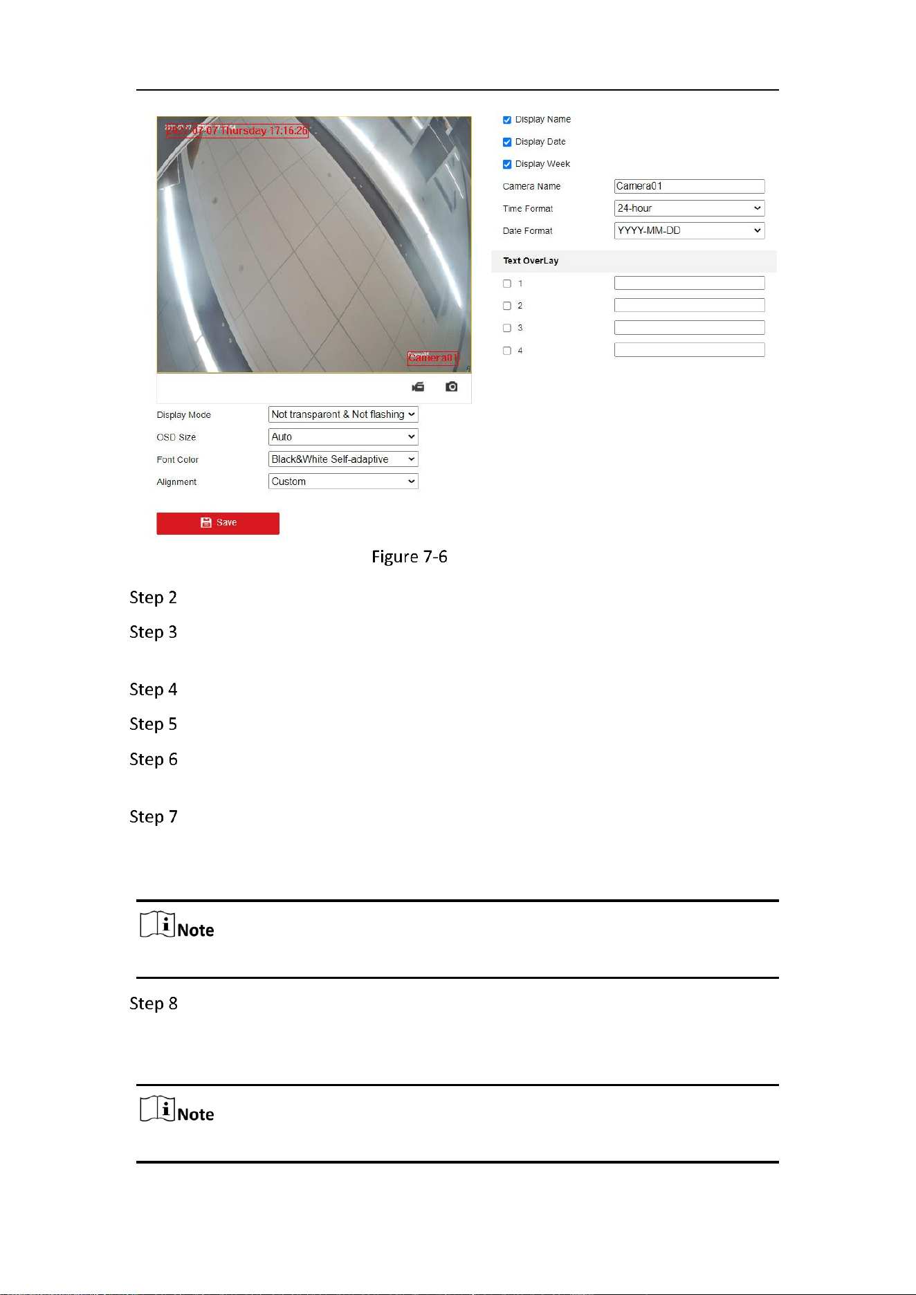
Mobile Network Camera • User Manual
68
OSD Settings
Go to Configuration > Image > OSD Settings.
Check the corresponding checkbox to select the display of camera name, date
or week if required.
Edit the camera name in the text field of Camera Name.
Select from the drop-down list to set the time format and date format.
Select from the drop-down list to set the time format, date format, display mode,
OSD size and OSD color.
Configure the text overlay settings.
1) Check the checkbox in front of the textbox to enable the on-screen display.
2) Input the characters in the textbox.
Up to 4 text overlays are configurable.
Adjust the position and alignment of text frames.
Left align, right align and custom are selectable. If you select custom, you can use the
mouse to click and drag text frames in the live view window to adjust their positions.
The alignment adjustment is only applicable to Text Overlay items.
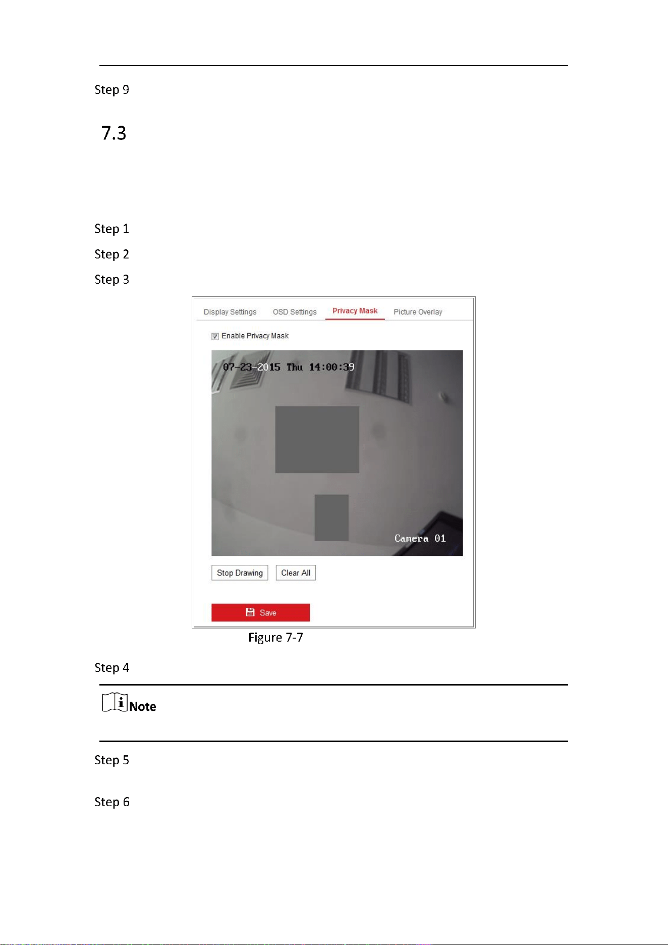
Mobile Network Camera • User Manual
69
Click Save to save the settings.
Privacy Mask
Purpose:
Privacy mask enables you to cover certain areas on the live video to prevent certain
spots in the monitoring area from being live viewed and recorded.
Go to Configuration > Image > Privacy Mask.
Check the checkbox of Enable Privacy Mask to enable this function.
Click Draw Area.
Privacy Mask Settings
Click and drag the mouse in the live video window to draw the mask area.
You are allowed to draw up to 4 areas on the same image.
Click Stop Drawing to finish drawing or click Clear All to clear all of the areas you
set without saving them.
Click Save to save the settings.
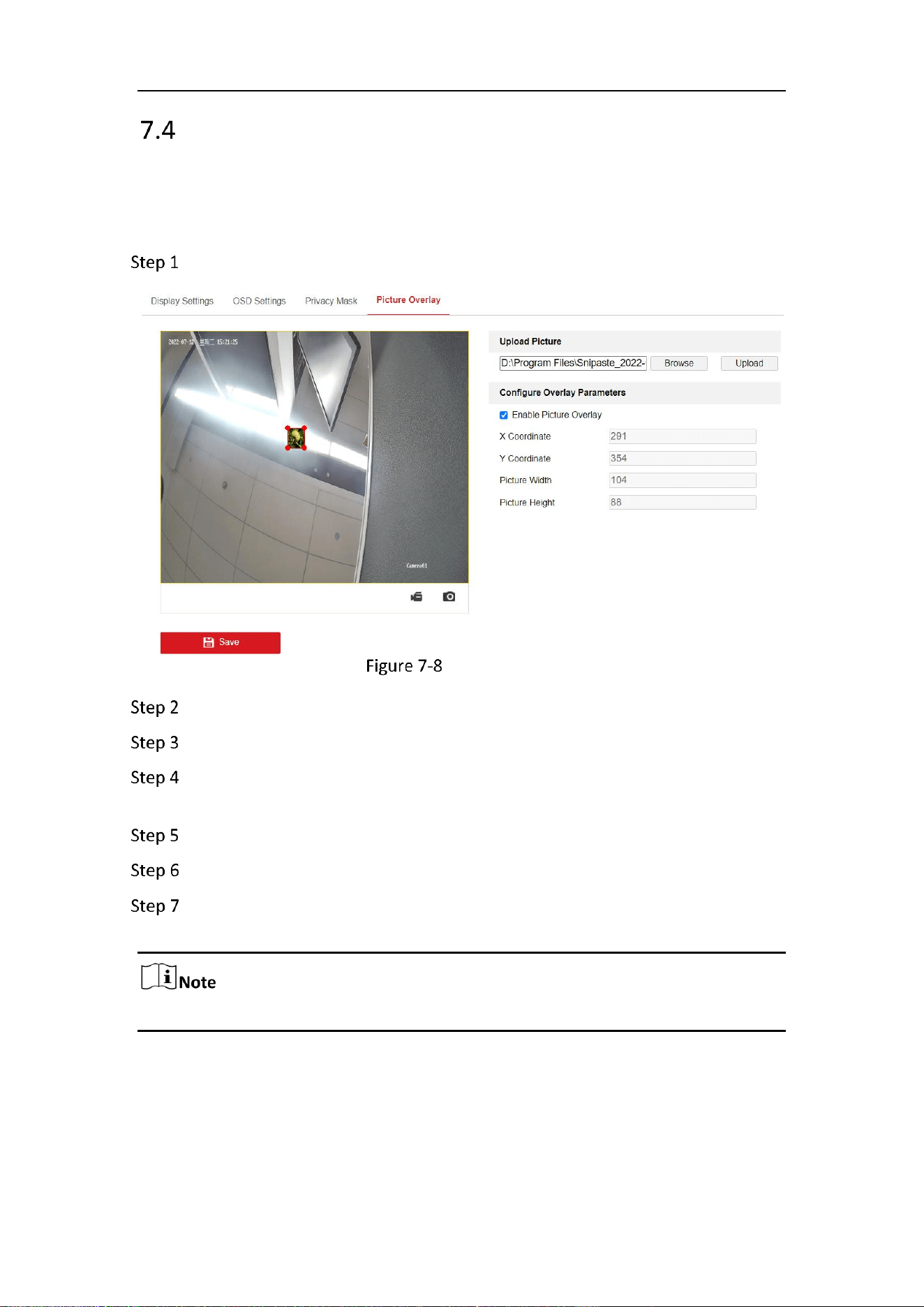
Mobile Network Camera • User Manual
70
Picture Overlay
Purpose:
Picture overlay enables you to overlay a picture on the image. This function enables a
certain enterprise or users to overlay their logo on the image.
Go to Configuration > Image > Picture Overlay.
Picture Overlay
Click Browse to select a picture.
Click Upload to upload it.
Check Enable Picture Overlay checkbox to enable the function. Uncheck this
checkbox to disable picture overlay.
Drag the red box to the desired place.
Click Save and the picture will appear in the red box.
To change the position of the picture overlay, upload the picture again and the
repeat the above procedures.
The picture must be in RGB24 bmp format and the maximum picture size is 128*128.
Mobile Network Camera • User Manual
71
Chapter 8 Event Settings
This section explains how to configure the network camera to respond to alarm events,
including basic event and smart event.
Basic Events
You can configure the basic events by following the instructions in this section,
including motion detection, video tampering and exception, etc. These events can
trigger the linkage methods, such as Notify Monitoring Center, Send Email, etc.
Check the checkbox of Notify Monitoring Center if you want the alarm information to
be pushed to PC or mobile client software as soon as the alarm is triggered.
Purpose:
Motion detection detects the moving objects in the configured monitoring area, and
a series of actions can be taken when the alarm is triggered.
In order to detect the moving objects accurately and reduce the false alarm rate,
normal configuration and expert configuration are selectable for different motion
detection environment.
Normal Configuration
Normal configuration adopts the same set of motion detection parameters in the
daytime and at night.
Tasks 1: Set the Motion Detection Area
Go to Configuration > Event > Basic Event > Motion Detection.
Check the checkbox of Enable Motion Detection.
Check the checkbox of Enable Dynamic Analysis for Motion if you want to mark
the detected objects with green rectangles.
Select Disable for rules if you don’t want the detected objected displayed with the
green rectangles. Select disable rules from Configuration > Local Configuration > Live
View Parameters-rules.
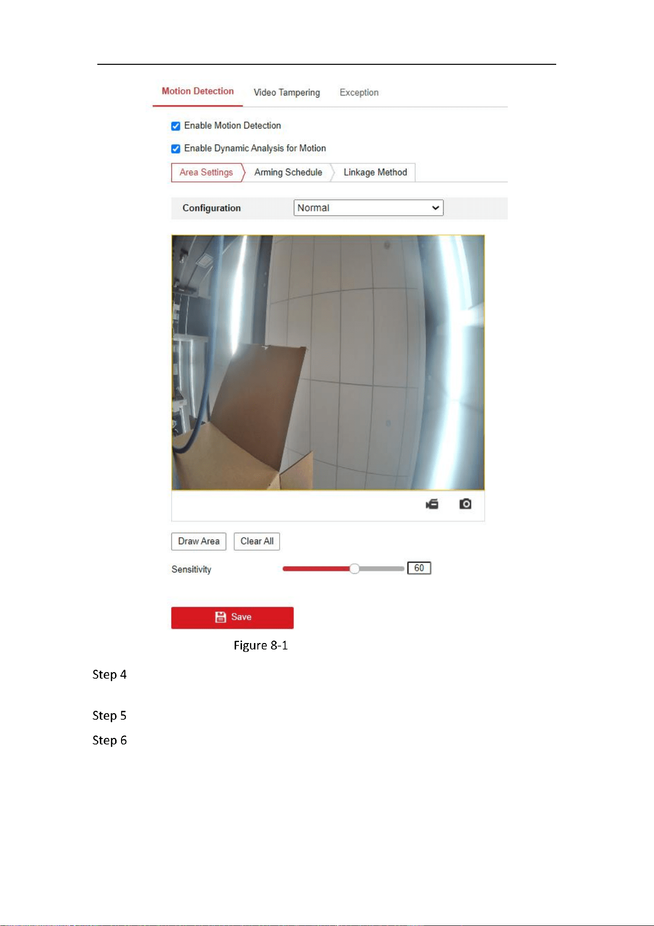
Mobile Network Camera • User Manual
72
Enable Motion Detection
Click Draw Area. Click and drag the mouse on the live video to draw a motion
detection area. Click Stop Drawing to finish drawing one area.
(Optional) Click Clear All to clear all of the areas.
(Optional) Move the slider to set the sensitivity of the detection.
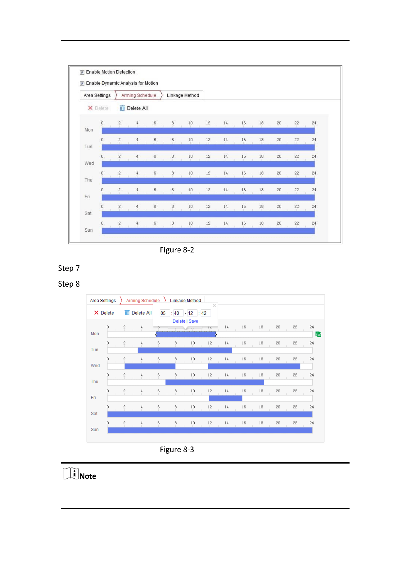
Mobile Network Camera • User Manual
73
Task 2: Set the Arming Schedule for Motion Detection
Arming Schedule
Click Arming Schedule to edit the arming schedule.
Click on the time bar and drag the mouse to select the time period.
Arming Schedule
Click on the selected time period, you can adjust the time period to the desired time
by either moving the time bar or input the exact time period.
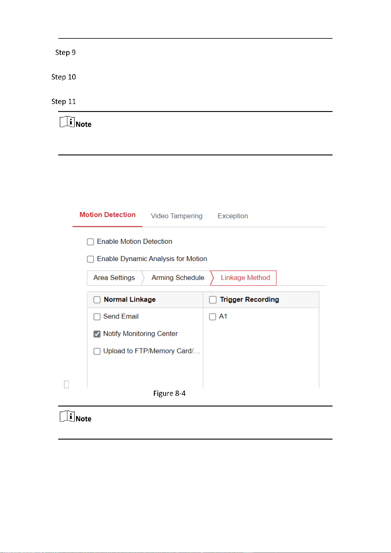
Mobile Network Camera • User Manual
74
(Optional) Click Delete to delete the current arming schedule, or click Save to
save the settings.
Move the mouse to the end of each day, a copy dialogue box pops up, and you
can copy the current settings to other days.
Click Save to save the settings.
The time of each period can’t be overlapped. Up to 8 periods can be configured for
each day.
Task 3: Set the Linkage Method for Motion Detection
Check the checkbox to select the linkage method. Send Email, Notify Monitoring
Center, Upload to FTP/Memory Card/NAS and Trigger Recording are selectable. You
can specify the linkage method when an event occurs.
Linkage Method
The linkage methods vary according to the different camera models.
Notify Monitoring Center
Send an exception or alarm signal to remote management software when an event
occurs.
Send Email
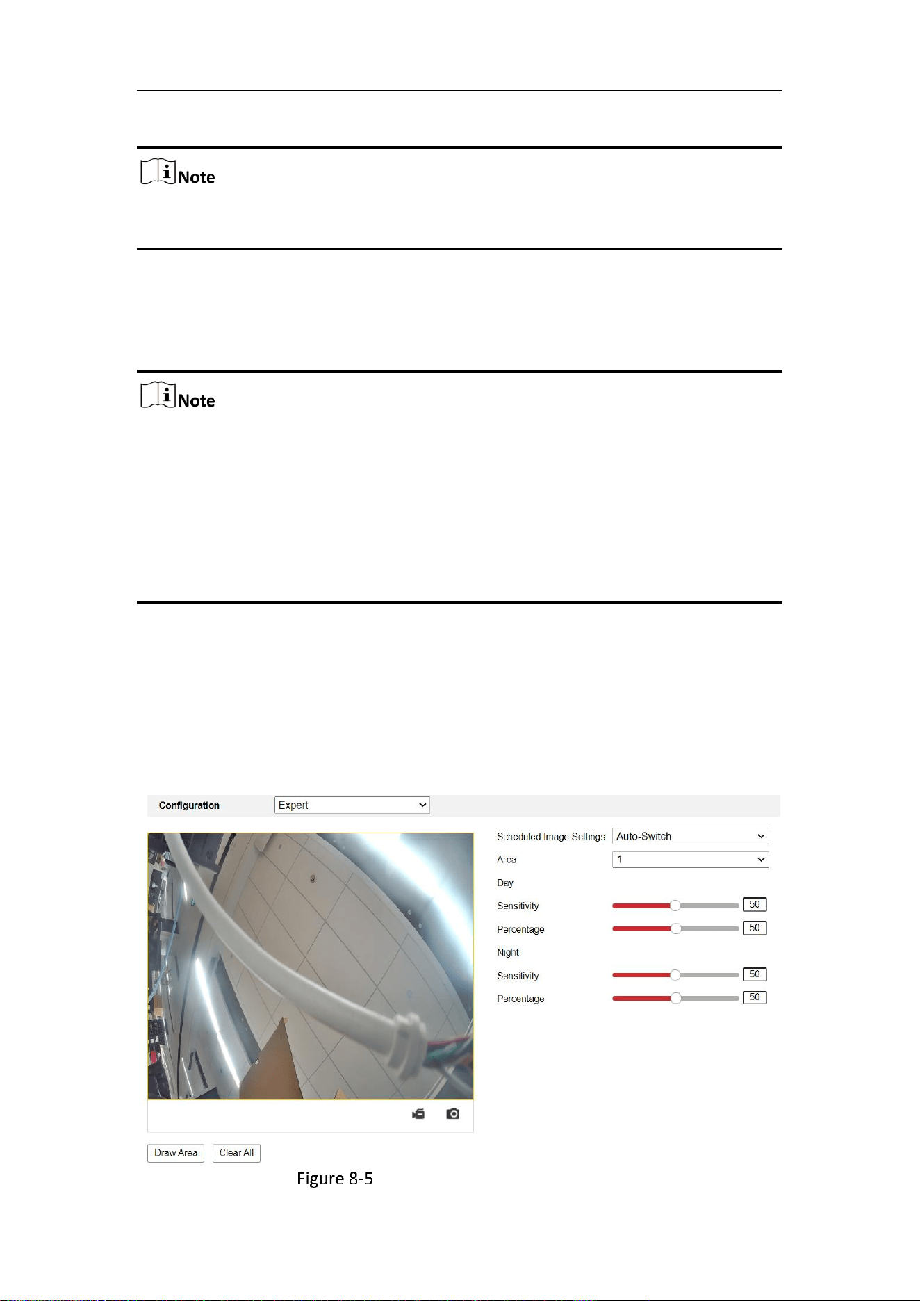
Mobile Network Camera • User Manual
75
Send an email with alarm information to a user or users when an event occurs.
To send the Email when an event occurs, please refer to Section 7.2.3 to complete
Email setup in advance.
Upload to FTP/Memory Card/NAS
Capture the image when an alarm is triggered and upload the picture to a FTP
server.
Set the FTP address and the remote FTP server first. Refer to 5.2.2 FTP for
detailed information.
Go to Configuration > Storage > Schedule Settings> Capture > Capture
Parameters page, enable the event-triggered snapshot, and set the capture
interval and capture number.
The captured image can also be uploaded to the available SD card or network
disk.
Trigger Recording
The video will be recorded when the motion is detected. You have to set the recording
schedule to realize this function. Please refer to Section 11.1 for detailed information.
Expert Configuration
Expert mode is mainly used to configure the sensitivity and proportion of object on
each area for different day/night switch.
Expert Mode of Motion Detection

Mobile Network Camera • User Manual
76
Day/Night Switch OFF
Draw the detection area as in the normal configuration mode. Up to 8 areas are
supported.
Select OFF for Switch Day and Night Settings.
Select the area by clicking the area No.
Slide the cursor to adjust the sensitivity and proportion of object on the area for
the selected area.
Set the arming schedule and linkage method as in the normal configuration
mode.
Click Save to save the settings.
Day/Night Auto-Switch
Draw the detection area as in the normal configuration mode. Up to 8 areas are
supported.
Select Auto-Switch for Switch Day and Night Settings.
Select the area by clicking the area No.
Slide the cursor to adjust the sensitivity and proportion of object on the area for
the selected area in the daytime.
Slide the cursor to adjust the sensitivity and proportion of object on the area for
the selected area at night.
Set the arming schedule and linkage method as in the normal configuration
mode.
Click Save to save the settings.
Day/Night Scheduled-Switch
Draw the detection area as in the normal configuration mode. Up to 8 areas are
supported.
Select Scheduled-Switch for Switch Day and Night Settings.
Day/Night Scheduled-Switch
Select the start time and the end time for the switch timing.
Select the area by clicking the area No..
Slide the cursor to adjust the sensitivity and proportion of object on the area for
the selected area in the daytime.
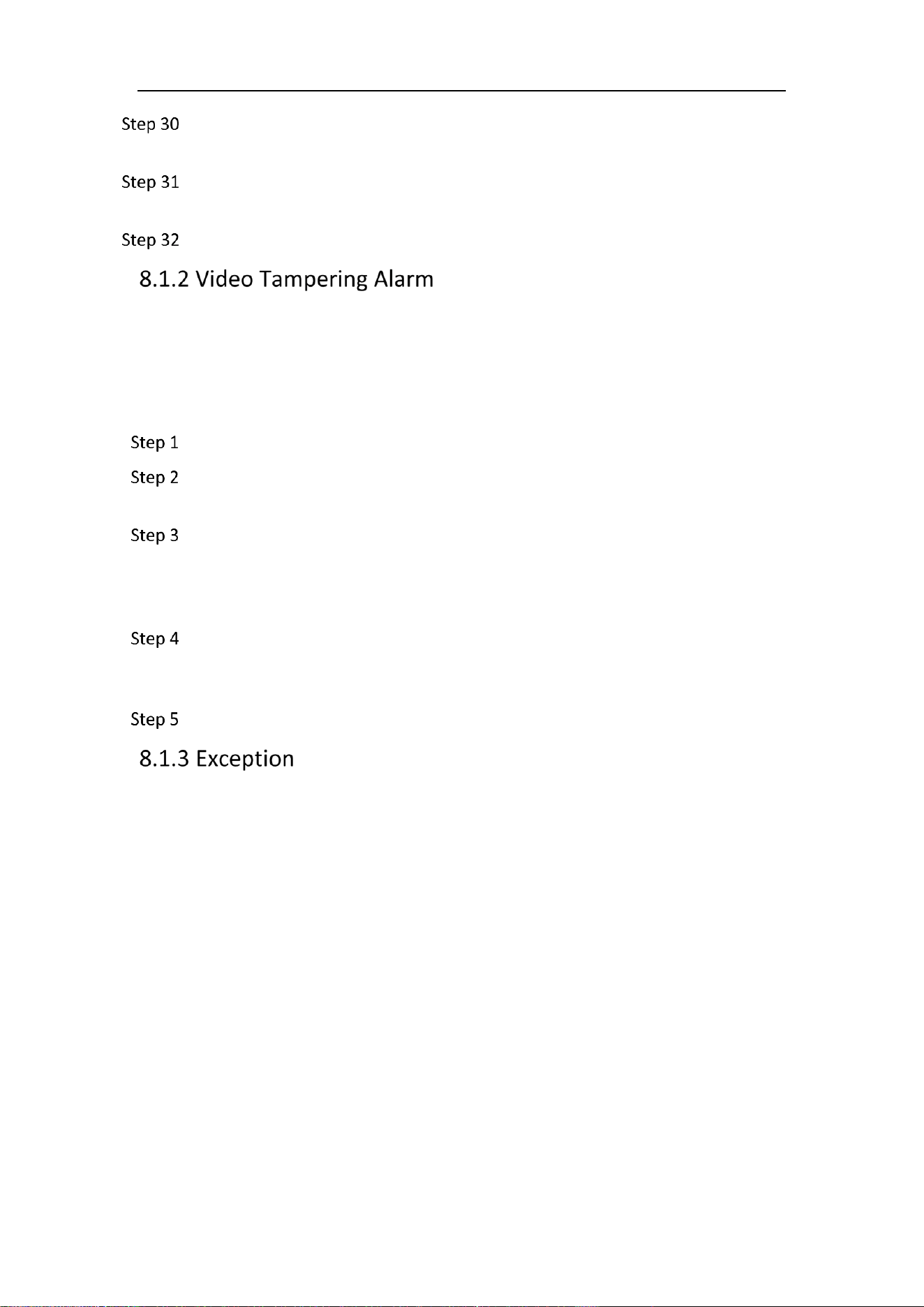
Mobile Network Camera • User Manual
77
Slide the cursor to adjust the sensitivity and proportion of object on the area for
the selected area at night.
Set the arming schedule and linkage method as in the normal configuration
mode.
Click Save to save the settings.
Purpose:
You can configure the camera to trigger the alarm when the lens is covered and take
certain alarm response actions.
Detection area for this alarm is the whole screen.
Go to Configuration > Event > Basic Event > Video Tampering.
Check Enable Video Tampering checkbox to enable the video tampering
detection.
Click Edit to edit the arming schedule for video tampering. The arming schedule
configuration is the same as the setting of the arming schedule for motion
detection. Refer to Task 2: Set the Arming Schedule for Motion Detection in
Section 8.1.1 .
Check the checkbox to select the linkage method taken for the video tampering.
Please refer to Task 3: Set the Linkage Method for Motion Detection in Section
8.1.1 .
Click Save to save the settings.
The exception type can be HDD full, HDD error, network disconnected, IP address
conflicted and illegal login to the cameras.
Mobile Network Camera • User Manual
78
Exception
Go to Configuration > Event > Basic Event > Exception.
Check the checkbox to set the actions taken for the Exception alarm. Refer to
Task 3: Set the Linkage Method for Motion Detection in Section 8.1.1 .
Click Save to save the settings.
Smart Events
Smart Events are incompatible with the third stream. For encoding performance, the
bitrate will drop after the smart event is on.
Smart Events includes the following function, as shown in the following table.

Mobile Network Camera • User Manual
79
Smart Events and their Linkage Method
Detection Function
Linkage Method
Defocus Detection
Scene Change Detection
Notify Monitoring Center, Send Email,
Upload to FTP/Memory Card/NAS,
Trigger Recording
Object detection
Notify Monitoring Center, Send Email,
Upload to FTP/Memory Card/NAS,
Trigger Recording
Intrusion Detection
Notify Monitoring Center, Send Email,
Upload to FTP/Memory Card/NAS,
Trigger Recording
Line Crossing Detection
Notify Monitoring Center, Send Email,
Upload to FTP/Memory Card/NAS,
Trigger Recording
Region Entrance Detection
Notify Monitoring Center, Send Email,
Upload to FTP/Memory Card/NAS,
Trigger Recording
Region Exiting Detection
Notify Monitoring Center, Send Email,
Upload to FTP/Memory Card/NAS,
Trigger Recording
Loitering Detection
Notify Monitoring Center, Send Email,
Upload to FTP/Memory Card/NAS,
Trigger Recording
People Gathering Detection
Notify Monitoring Center, Send Email,
Upload to FTP/Memory Card/NAS,
Trigger Recording
Fast Moving Detection
Notify Monitoring Center, Send Email,
Upload to FTP/Memory Card/NAS,
Trigger Recording
Parking Detection
Notify Monitoring Center, Send Email,
Upload to FTP/Memory Card/NAS,
Trigger Recording
Mobile Network Camera • User Manual
80
Unattended Baggage Detection
Notify Monitoring Center, Send Email,
Upload to FTP/Memory Card/NAS,
Trigger Recording
Some of these functions have the options of setting regions, threshold and sensitivity
for detection.
Region: A pre-defined vertexes area on the live view image. Targets, such as,
people, vehicle or other objects, who enter and loiter in the region will be detected
and trigger the set alarm.
Threshold: Range [0 s-10 s], the threshold for the time of the object loitering in
the region. If you set the value as 0, alarm is triggered immediately after the object
entering the region.
Sensitivity: Range [1-100]. Sensitivity stands for the percentage of the body part
of an acceptable target that enters the pre-defined region.
Sensitivity = 100 – S
1
/S
T
*100
S
1
stands for the target body part that goes across the pre-defined region. S
T
stands for
the complete target body.
Example: if you set the value as 60, the action can be counted as an intrusion only
when 40 percent body part enters the region.
In general, the higher the sensitivity is, the easier the alarm will be triggered.
For each of these steps, you can repeat the above steps to configure other
regions. Up to 4 regions can be set. You can click the Clear button to clear all pre-
defined regions.
Click Arming Schedule to set the arming schedule.
Click Linkage Method to select the linkage methods for intrusion detection,
including Notify Monitoring Center, Send Email, Upload to FTP/Memory
Card/NAS, and Trigger Channel.
Purpose:
The image blur caused by defocus of the lens can be detected, and some certain
actions can be taken when the alarm is triggered.
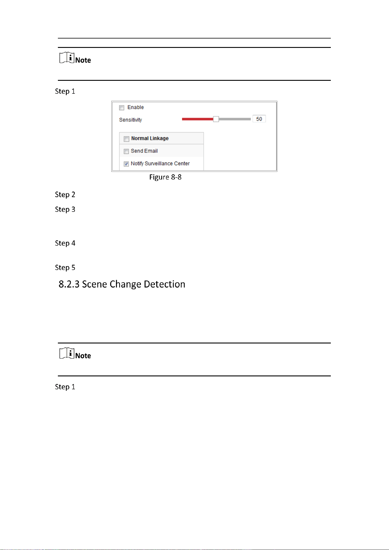
Mobile Network Camera • User Manual
81
Defocus detection function varies according to different camera models.
Go to Configuration > Event > Smart Event > Defocus Detection.
Defocus Detection
Check the checkbox of Enable to enable the function.
Click-and-drag the slider to set the detection sensitivity. The sensitivity value
ranges from 1 to 100, and the higher the value is, the more easily the defocus
image can trigger the alarm.
Select the linkage methods for defocus, including Notify Monitoring Center,
Send Email and Upload to FTP.
Click Save to save the settings.
Purpose:
Scene change detection function detects the change of monitoring environment
affected by the external factors, such as the intentional rotation of the camera. Some
certain actions can be taken when the alarm is triggered.
Scene change detection function varies according to different camera models.
Go to Configuration > Event > Smart Event > Scene Change Detection.
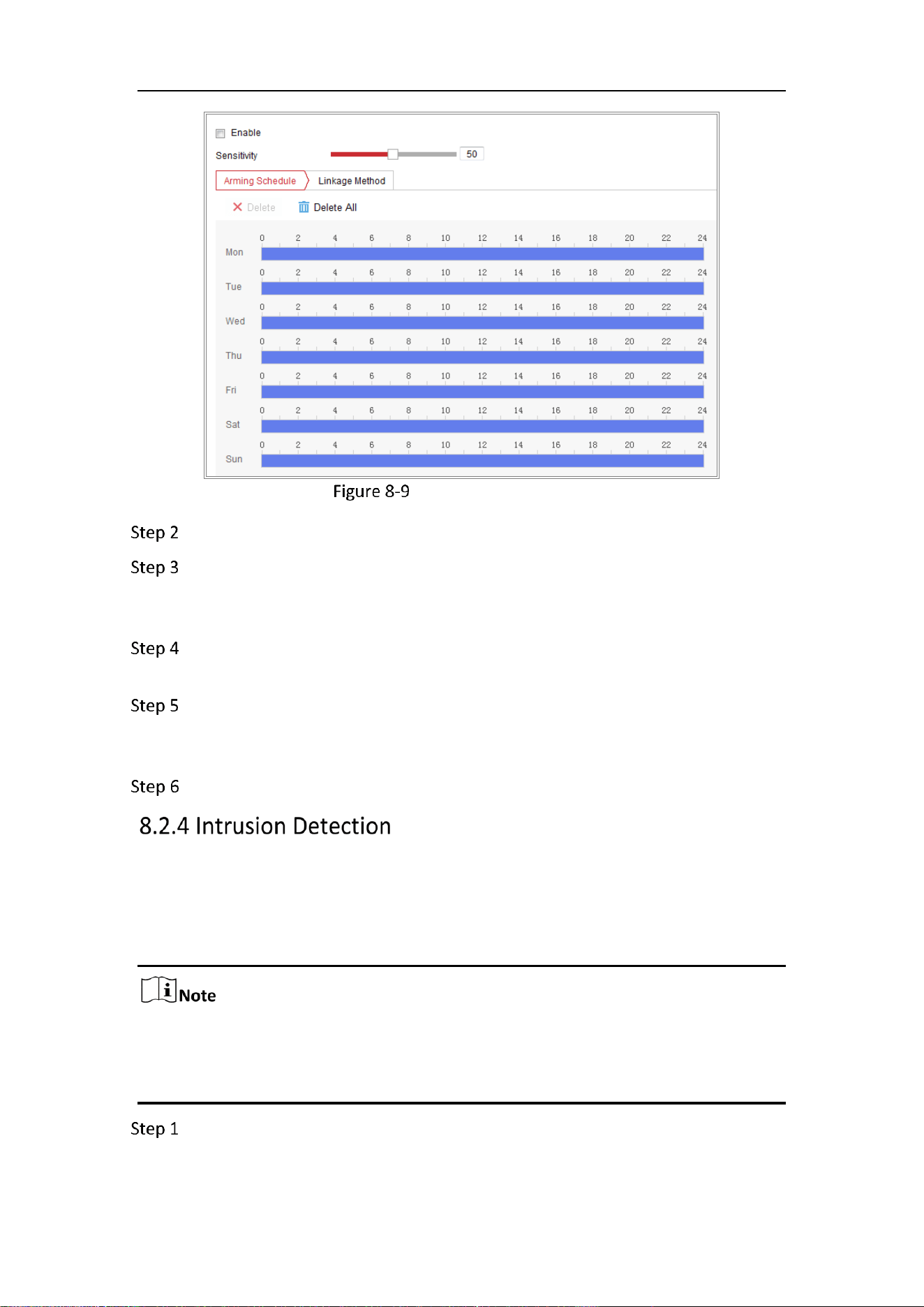
Mobile Network Camera • User Manual
82
Scene Change Detection
Check the checkbox of Enable to enable the function.
Click-and-drag the slider to set the detection sensitivity. The sensitivity value
ranges from 1 to 100, and the higher the value is, the more easily the change of
scene can trigger the alarm.
Click Arming Schedule to set the arming schedule. Refer to Task 2 Set the
Arming Schedule for Motion Detection in Section 8.1.1 for detailed steps.
Click Linkage Method to select the linkage methods for scene change, including
Notify Monitoring Center, Send Email, Upload to FTP/Memory Card/NAS and
Trigger Channel.
Click Save to save the settings.
Purpose:
Intrusion detection function detects people, vehicle or other objects which enter and
loiter in a pre-defined virtual region, and some certain actions can be taken when the
alarm is triggered.
Intrusion detection function varies according to different camera models.
Then the alarm will stop if the intruding object stays still, and it will start again
when the intruding object moves.
Go to Configuration> Event > Smart Event > Intrusion Detection.
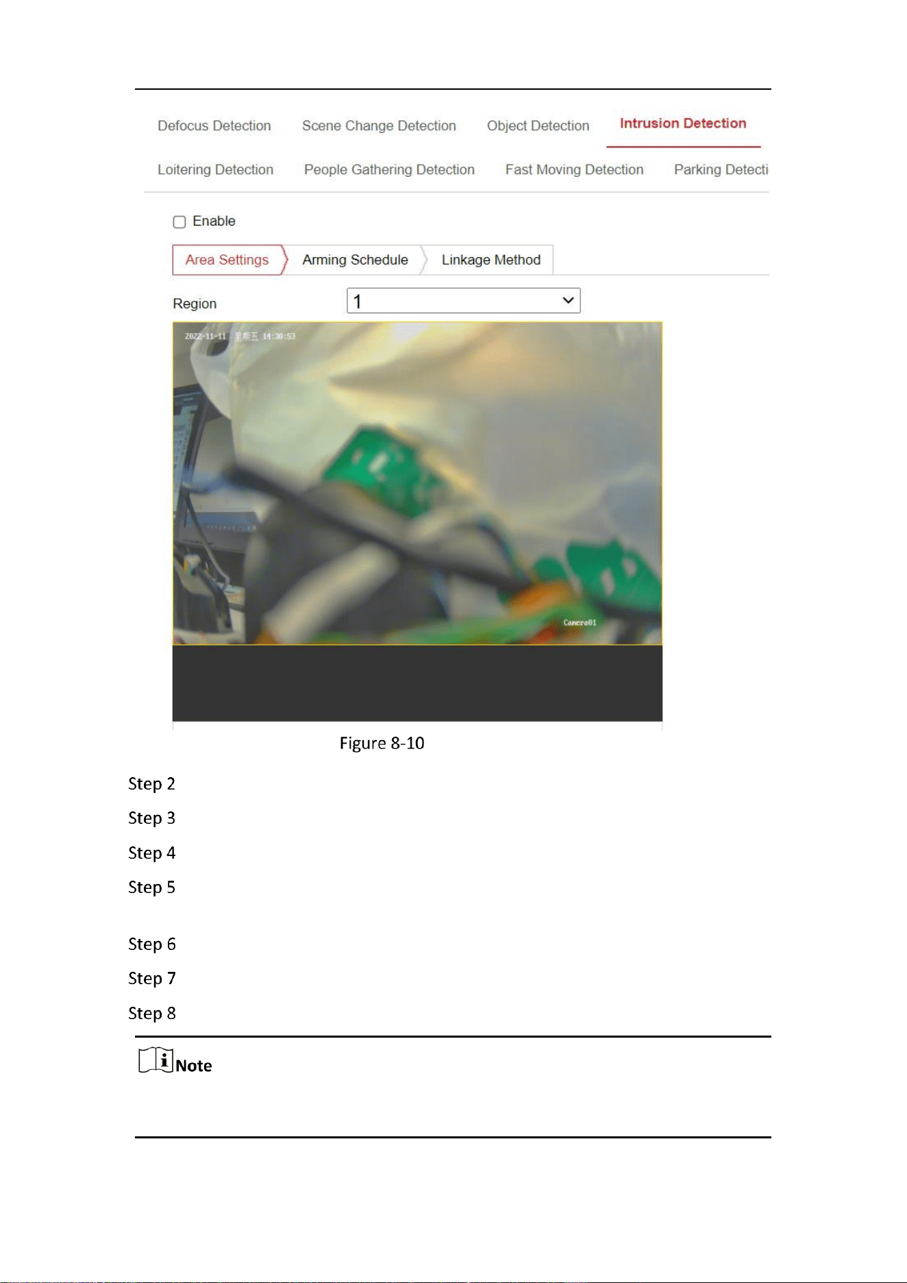
Mobile Network Camera • User Manual
83
Intrusion Detection
Check the checkbox of Enable to enable the function.
Select a region number from the drop-down list of Region.
Click Area Settings tab and click Draw Area button to start the region drawing.
Click on the live video to specify the four vertexes of the detection region, and
right click to complete drawing.
Click Stop Drawing when finish drawing.
Set the time threshold for intrusion detection.
Drag the slider to set the sensitivity value.
The Sensitivity of the detection is supported by certain models. Refer to actual
display for details.
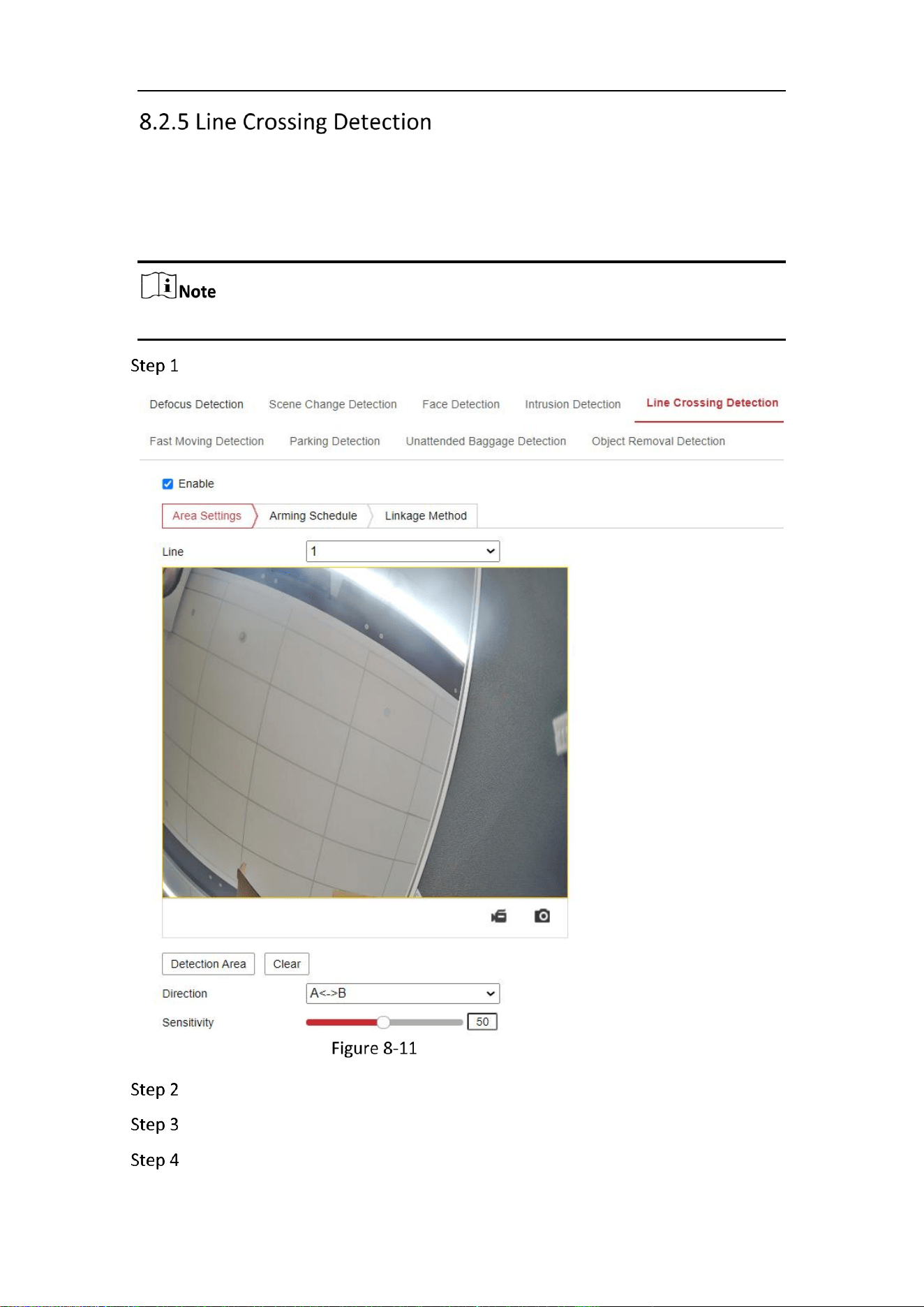
Mobile Network Camera • User Manual
84
Purpose:
Line crossing detection function detects people, vehicle or other objects which cross a
pre-defined virtual line, and some certain actions can be taken when the alarm is
triggered.
Line crossing detection function varies according to different camera models.
Go to Configuration > Event > Smart Event > Line Crossing Detection.
Line Crossing Detection
Check the checkbox of Enable to enable the function.
Select the line from the drop-down list.
Click Area Settings tab and click Draw Area button, and a virtual line is displayed
on the live video.
Mobile Network Camera • User Manual
85
Drag the line, and you can locate it on the live video as desired. Click on the line,
two red squares are displayed on each end, and you can click-and-drag one of
the red squares to define the shape and length of the line.
Select the direction for line crossing detection. And you can select the directions
as A<->B, A ->B, and B->A.
A<->B: The object going across the plane with both directions can be detected
and alarms are triggered.
A->B: Only the object crossing the configured line from the A side to the B side
can be detected.
B->A: Only the object crossing the configured line from the B side to the A side
can be detected.
Click Stop Drawing when finish drawing.
Drag the slider to set the sensitivity value.
Purpose:
Region entrance detection function detects people, vehicle or other objects which
enter a pre-defined virtual region from the outside place, and some certain actions
can be taken when the alarm is triggered.
The difference between intrusion detection and region entrance detection lies in
the way that the object enters the region: regions entrance detection will only
trigger the alarm when the object enters the region by crossing a cordon,
whereas the intrusion detection does not specify the way of entrance.
Intrusion detection, region exiting detection and region entrance detection will
only send alarm once, and stop when the object stay still. Another alarm will be
sent when the object moves again.
Go to Configuration > Event > Smart Event > Region Entrance Detection.
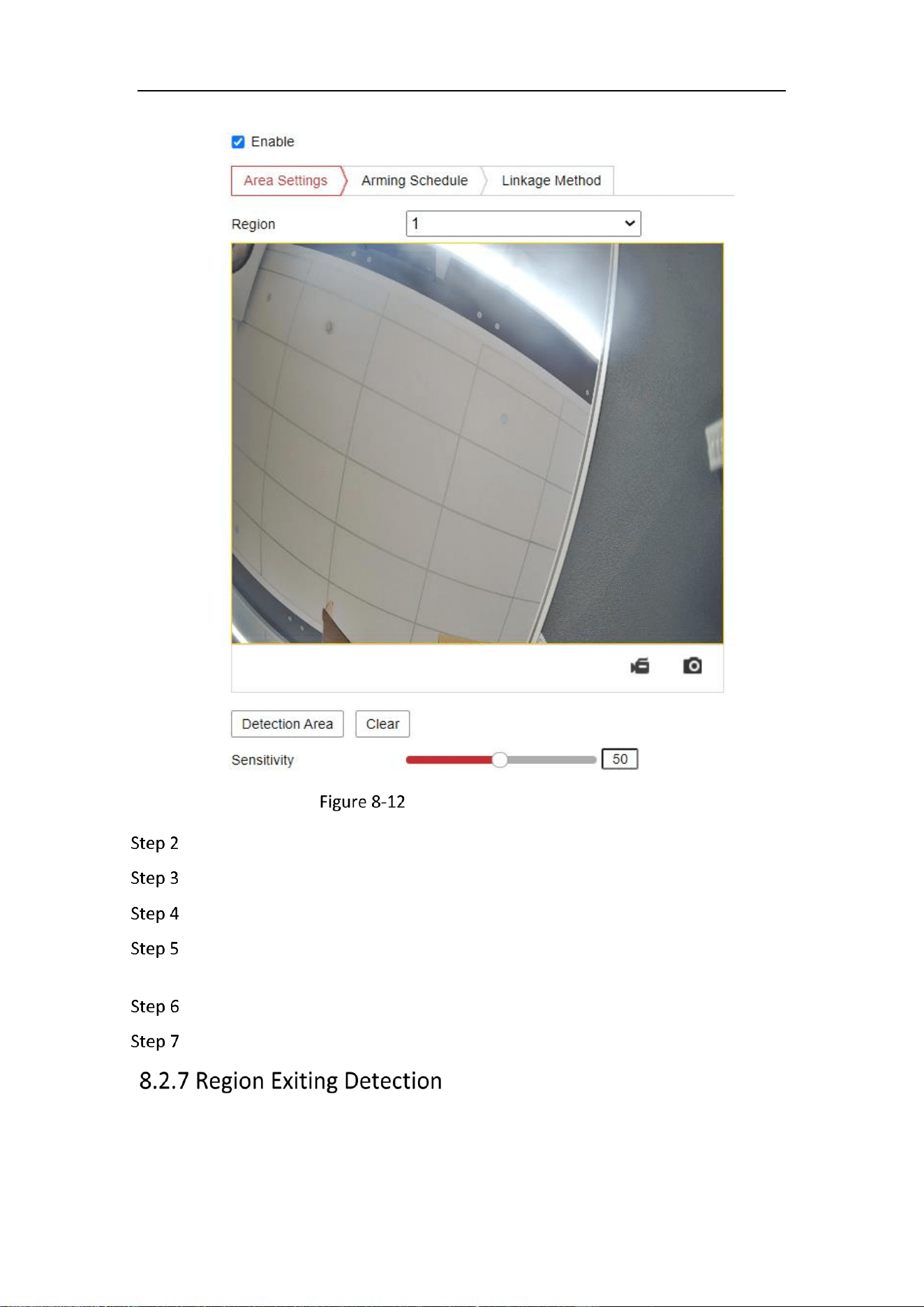
Mobile Network Camera • User Manual
86
Region Entrance Detection
Check the Enable checkbox to enable the function.
Select the Region from the drop-down list for detection settings.
Click Area Settings and click Draw Area button to start the area drawing.
Click on the live video to specify the four vertexes of the detection region, and
right click to complete drawing.
Click Stop Drawing when finish drawing.
Drag the slider to set the sensitivity value.
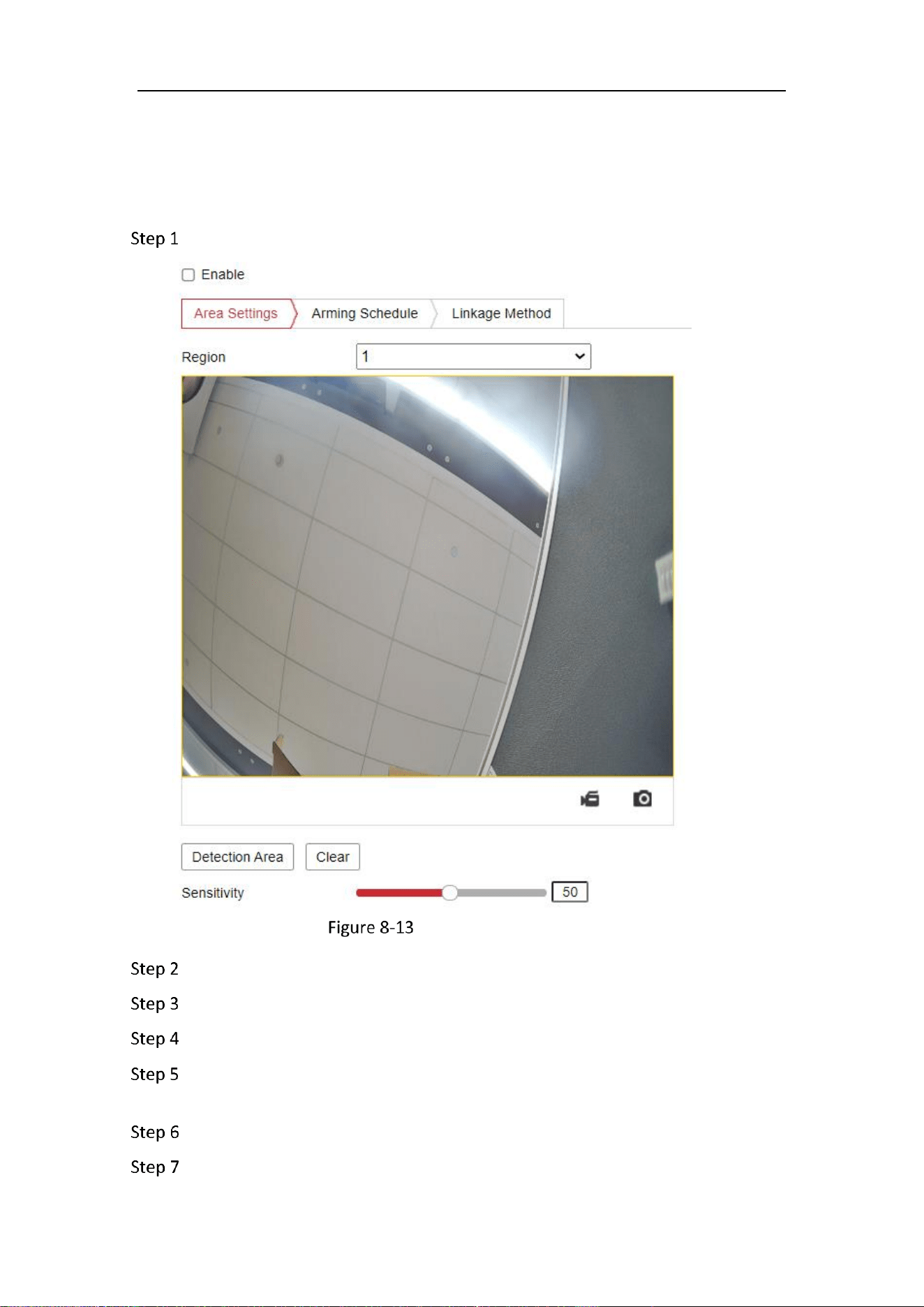
Mobile Network Camera • User Manual
87
Purpose:
Region exiting detection function detects people, vehicle or other objects which exit
from a pre-defined virtual region, and some certain actions can be taken when the
alarm is triggered.
Go to Configuration > Event > Smart Event > Region Exiting Detection.
Region Exiting Detection
Check Enable checkbox to enable the function.
Select the Region from the drop-down list for detection settings.
Click Area Settings and click Draw Area button to start the area drawing.
Click on the live video to specify the four vertexes of the detection region, and
right click to complete drawing.
Click Stop Drawing when finish drawing.
Drag the slider to set the sensitivity value.
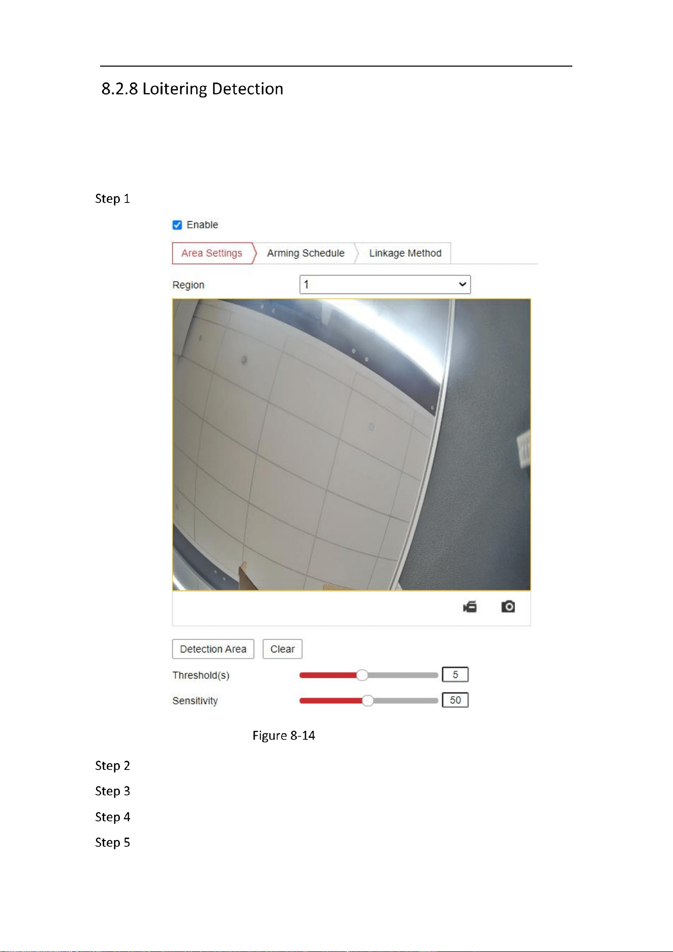
Mobile Network Camera • User Manual
88
Purpose:
Loitering Detection function detects the objects’s stay in the pre-defined region over
an extended period of time, such as the exhibits on display, and a series of actions can
be taken when the alarm is triggered.
Go to Configuration > Event > Smart Event > Loitering Detection.
Loitering Detection
Check Enable checkbox to enable the function.
Select the Region from the drop-down list for detection settings.
Click Area Settings and click Draw Area button to start the area drawing.
Click on the live video to specify the four vertexes of the detection region, and
right click to complete drawing.
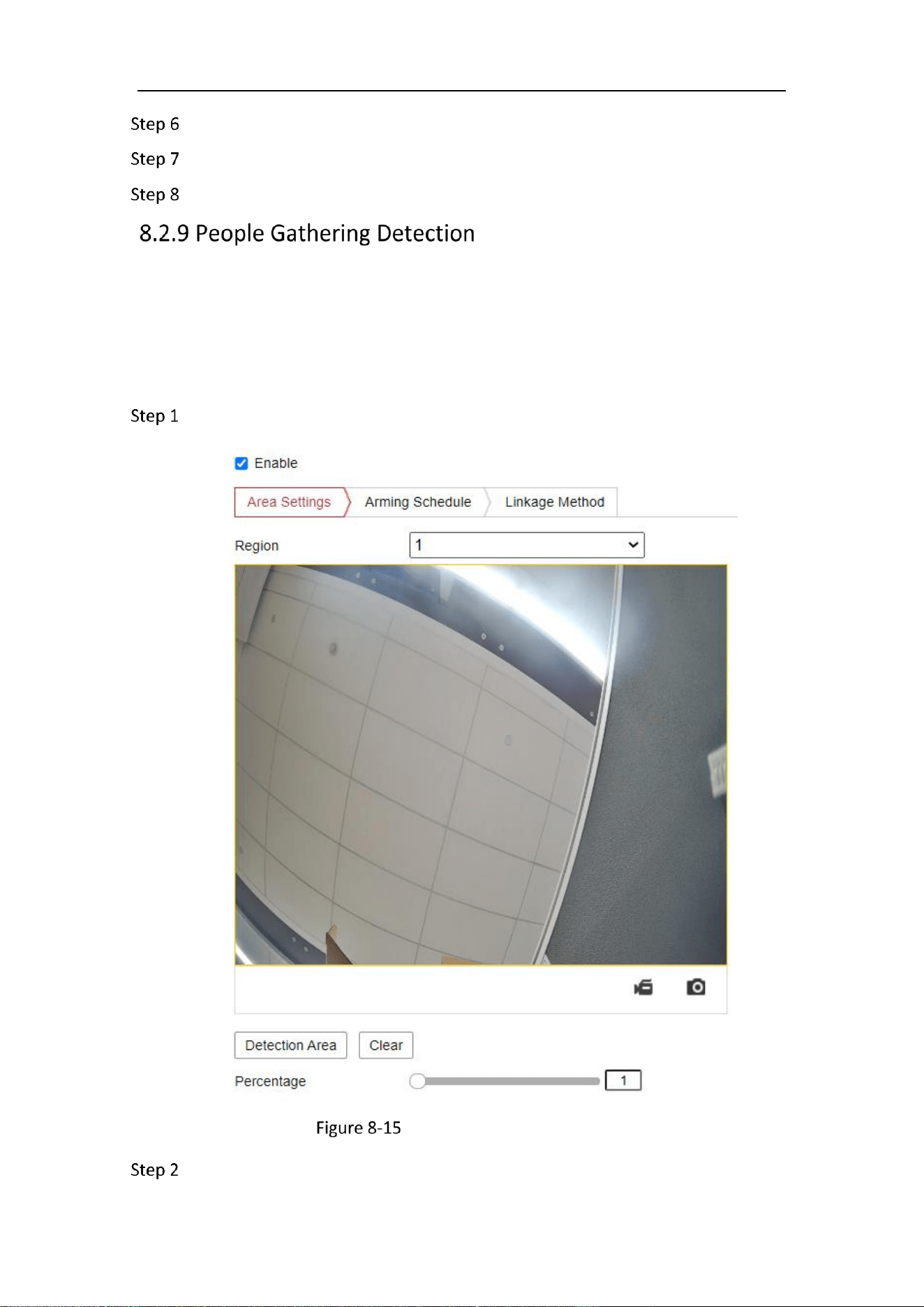
Mobile Network Camera • User Manual
89
Click Stop Drawing when finish drawing.
Set the time threshold for object removal detection.
Drag the slider to set the sensitivity value.
Purpose:
People Gathering Detection function detects the density of people in the pre-defined
region, such as the exhibits on display, and a series of actions can be taken when the
density of over a preset percentage.
Go to Configuration > Event > Smart Event > People Gathering Detection.
People Gathering Detection
Check Enable checkbox to enable the function.
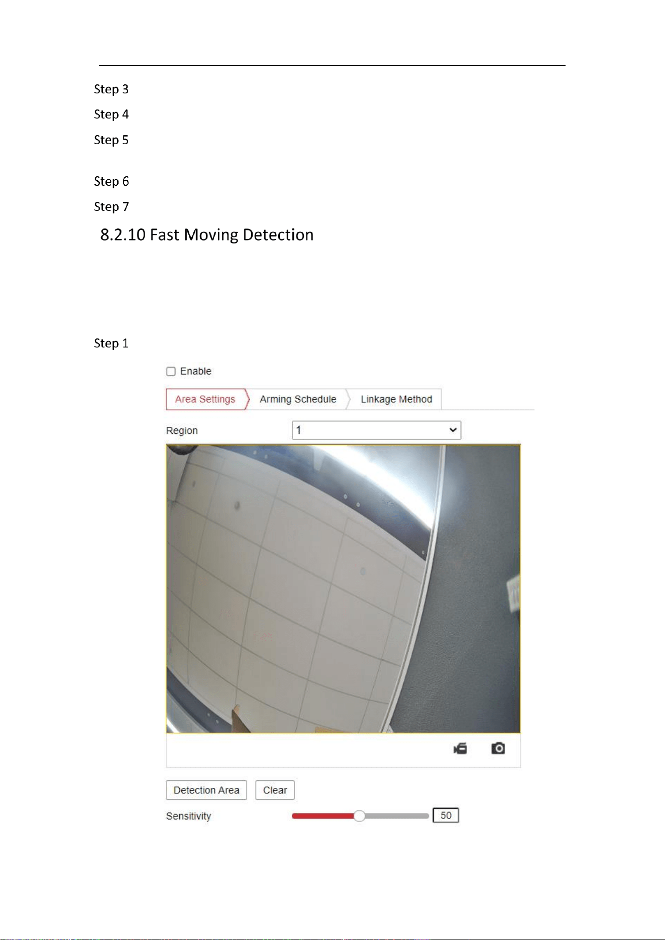
Mobile Network Camera • User Manual
90
Select the Region from the drop-down list for detection settings.
Click Area Settings and click Draw Area button to start the area drawing.
Click on the live video to specify the four vertexes of the detection region, and
right click to complete drawing.
Click Stop Drawing when finish drawing.
Drag the slider to set the percentage value.
Purpose:
Object removal detection function detects the objects removed from the pre-defined
region, such as the exhibits on display, and a series of actions can be taken when the
alarm is triggered.
Go to Configuration > Event > Smart Event > Fast Moving Detection.
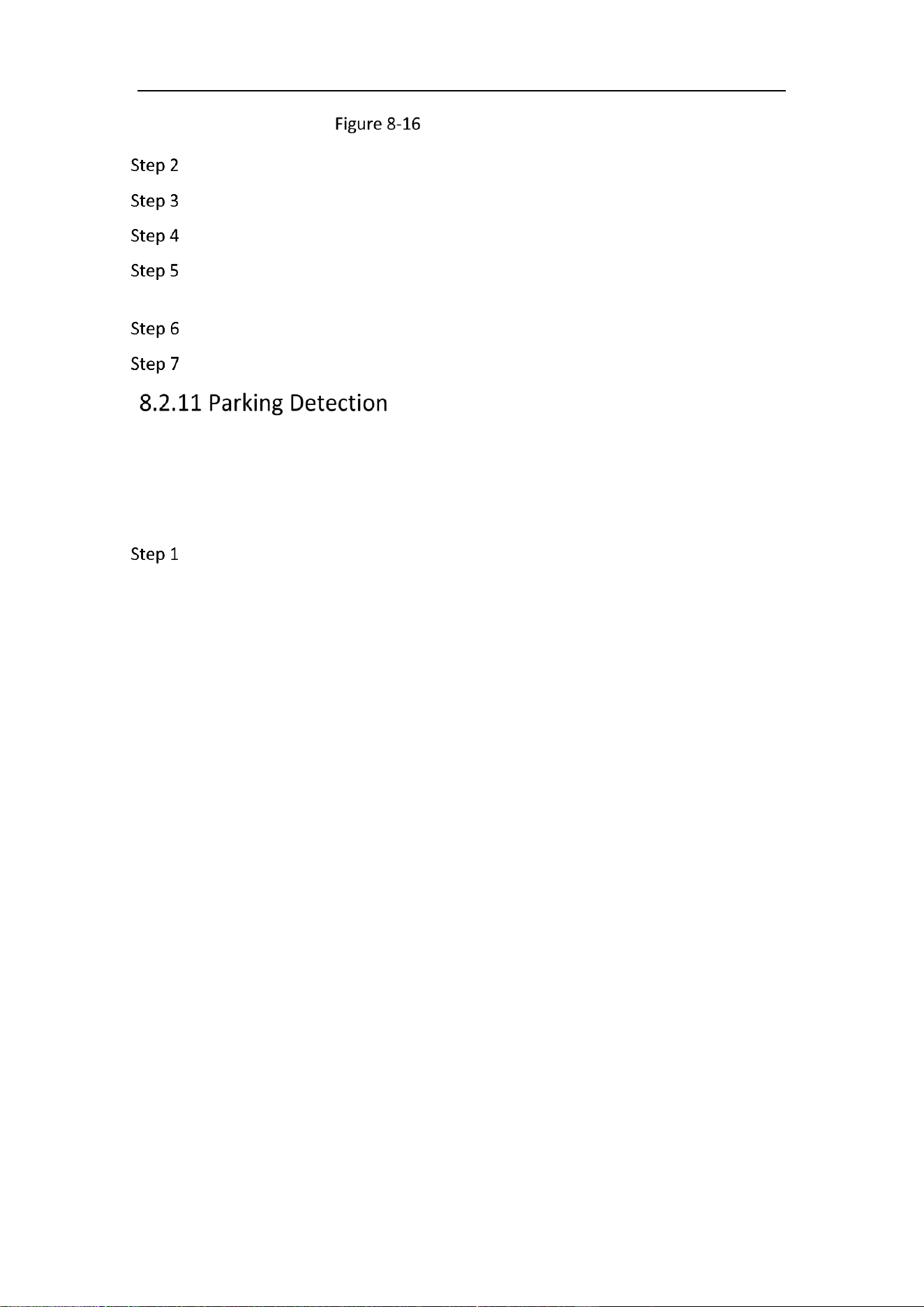
Mobile Network Camera • User Manual
91
Fast Moving Detection
Check Enable checkbox to enable the function.
Select the Region from the drop-down list for detection settings.
Click Area Settings and click Draw Area button to start the area drawing.
Click on the live video to specify the four vertexes of the detection region, and
right click to complete drawing.
Click Stop Drawing when finish drawing.
Drag the slider to set the sensitivity value.
Purpose:
Parking Detection function detects the time that vehicles stay in the pre-defined region,
such as the exhibits on display, and a series of actions can be taken when the alarm is
triggered.
Go to Configuration > Event > Smart Event > Parking Detection.
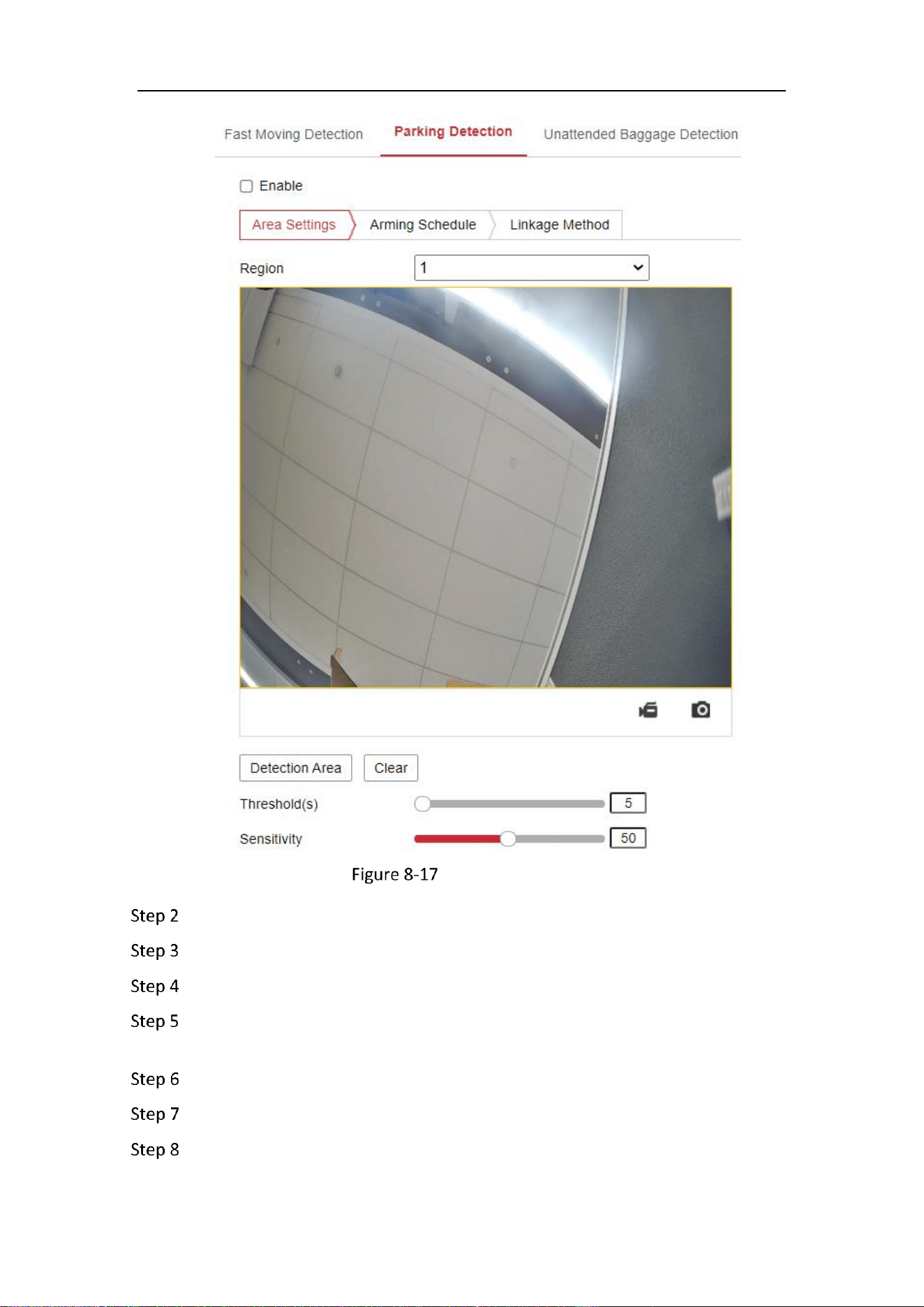
Mobile Network Camera • User Manual
92
Parking Detection
Check Enable checkbox to enable the function.
Select the Region from the drop-down list for detection settings.
Click Area Settings and click Draw Area button to start the area drawing.
Click on the live video to specify the four vertexes of the detection region, and
right click to complete drawing.
Click Stop Drawing when finish drawing.
Set the time threshold for object removal detection.
Drag the slider to set the sensitivity value.
Mobile Network Camera • User Manual
93
Purpose:
Unattended baggage detection function detects the objects left over in the pre-
defined region such as the baggage, purse, dangerous materials, etc. A series of actions
can be taken when the alarm is triggered.
Go to Configuration > Event > Smart Event > Unattended Baggage Detection.
Unattended Baggage Detection
Check Enable checkbox to enable the function.
Select the Region from the drop-down list for detection settings.
Click Area Settings and click Draw Area to start the area drawing.
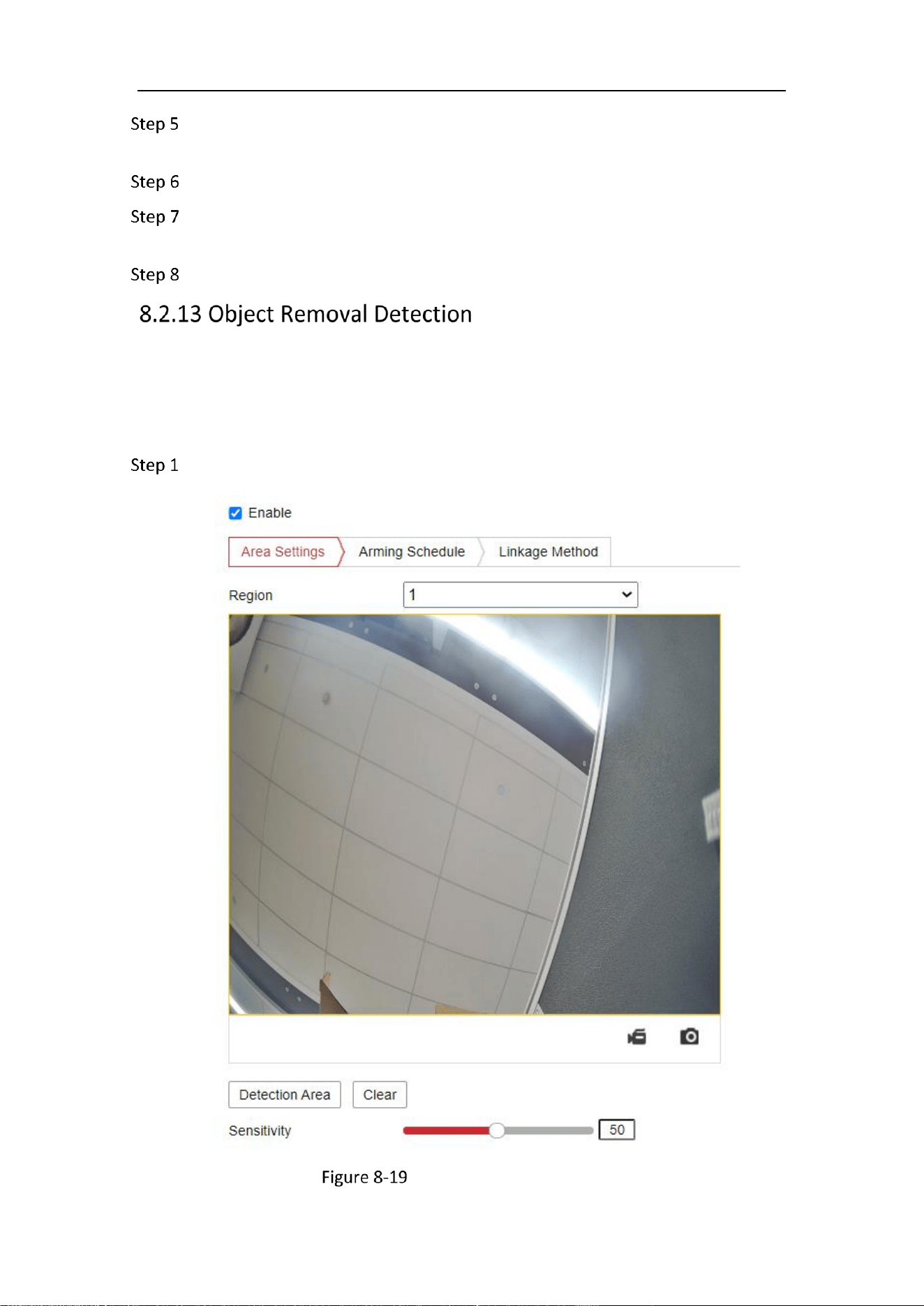
Mobile Network Camera • User Manual
94
Click on the live video to specify the four vertexes of the detection region, and
right click to complete drawing.
Click Stop Drawing when finish drawing.
Set the time threshold and detection sensitivity for unattended baggage
detection.
Drag the slider to set the sensitivity value.
Purpose:
Object removal detection function detects the objects removed from the pre-defined
region, such as the exhibits on display, and a series of actions can be taken when the
alarm is triggered.
Go to Configuration > Event > Smart Event > Object Removal Detection.
Object Removal Detection

Mobile Network Camera • User Manual
95
Check Enable checkbox to enable the function.
Select the Region from the drop-down list for detection settings.
Click Area Settings and click Draw Area button to start the area drawing.
Click on the live video to specify the four vertexes of the detection region, and
right click to complete drawing.
Click Stop Drawing when finish drawing.
Set the time threshold for object removal detection.
Drag the slider to set the sensitivity value.
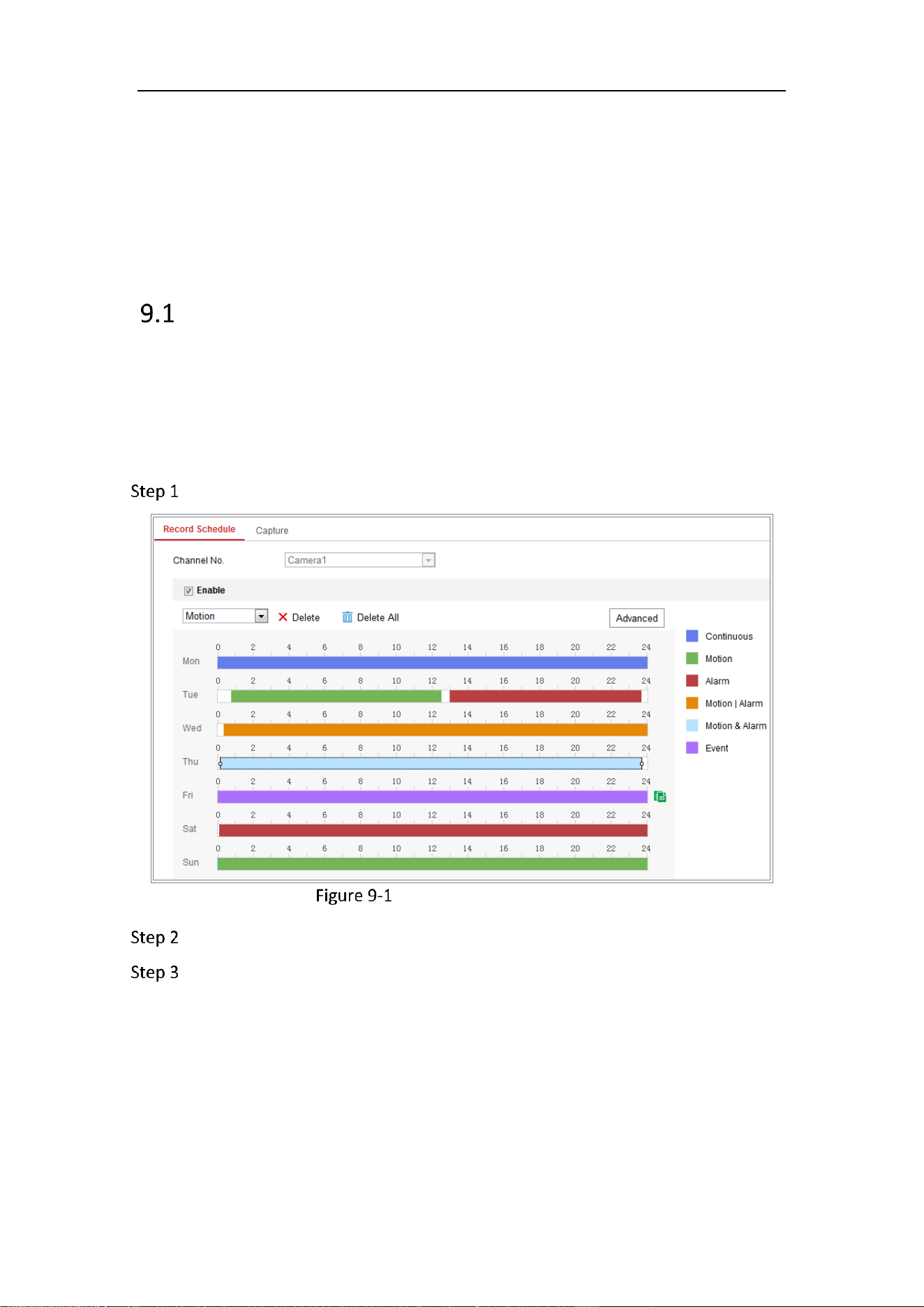
Mobile Network Camera • User Manual
96
Chapter 9 Storage Settings
Before you start:
To configure record settings, make sure that you have the network storage device or
local storage device configured.
Record Schedule
Purpose:
There are two kinds of recording for the cameras: manual recording and scheduled
recording. In this section, you can follow the instructions to configure the scheduled
recording. By default, the record files of scheduled recording are stored in the local
storage or in the network disk.
Go to Configuration > Storage > Schedule Settings > Record Schedule.
Recording Schedule Interface
Check the checkbox of Enable to enable scheduled recording.
Click Advanced to set the camera record parameters.

Mobile Network Camera • User Manual
97
Record Parameters
Pre-record: The time you set to start recording before the scheduled time or the
event. For example, if an alarm triggers recording at 10:00, and the pre-record time is
set as 5 seconds, the camera starts to record at 9:59:55.
The Pre-record time can be configured as No Pre-record, 5 s, 10 s, 15 s, 20 s, 25 s, 30 s
or not limited.
Post-record: The time you set to stop recording after the scheduled time or the
event. For example, if an alarm triggered recording ends at 11:00, and the post-
record time is set as 5 seconds, the camera records until 11:00:05.
The Post-record time can be configured as 5 s, 10 s, 30 s, 1 min, 2 min, 5 min or 10 min.
Stream Type: Select the stream type for recording.
The record parameter configurations vary depending on the camera model.
Select a Record Type. The record type can be either Continuous or Event.
Continuous
If you select Continuous, the video will be recorded automatically according to the
time of the schedule.
Record Triggered by Events
If you select Event, the video will be recorded if any of the events is triggered. Besides
configuring the recording schedule, you have to configure the event settings.
Select the record type, and click-and-drag the mouse on the time bar to set the
record schedule.
Click Save to save the settings.
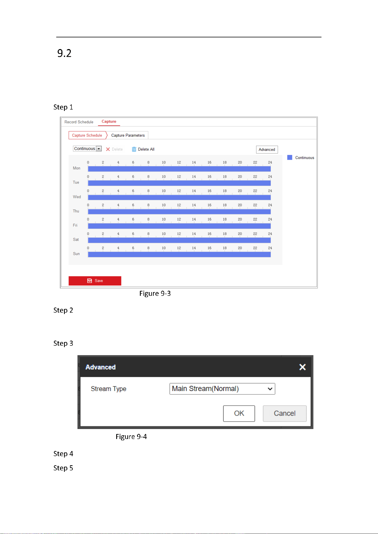
Mobile Network Camera • User Manual
98
Capture Schedule
Purpose:
You can configure the scheduled snapshot and event-triggered snapshot. The captured
picture can be stored in the local storage or network storage.
Go to Configuration > Storage > Storage Settings > Capture.
Capture Configuration
Go to Capture Schedule tab to configure the capture schedule by click-and-drag
the mouse on the time bar. You can copy the record schedule to other days by
clicking the green copy icon on the right of each time bar.
Click Advanced to select stream type.
Advanced Setting of Capture Schedule
Click Save to save the settings.
Go to Capture Parameters tab to configure the capture parameters.
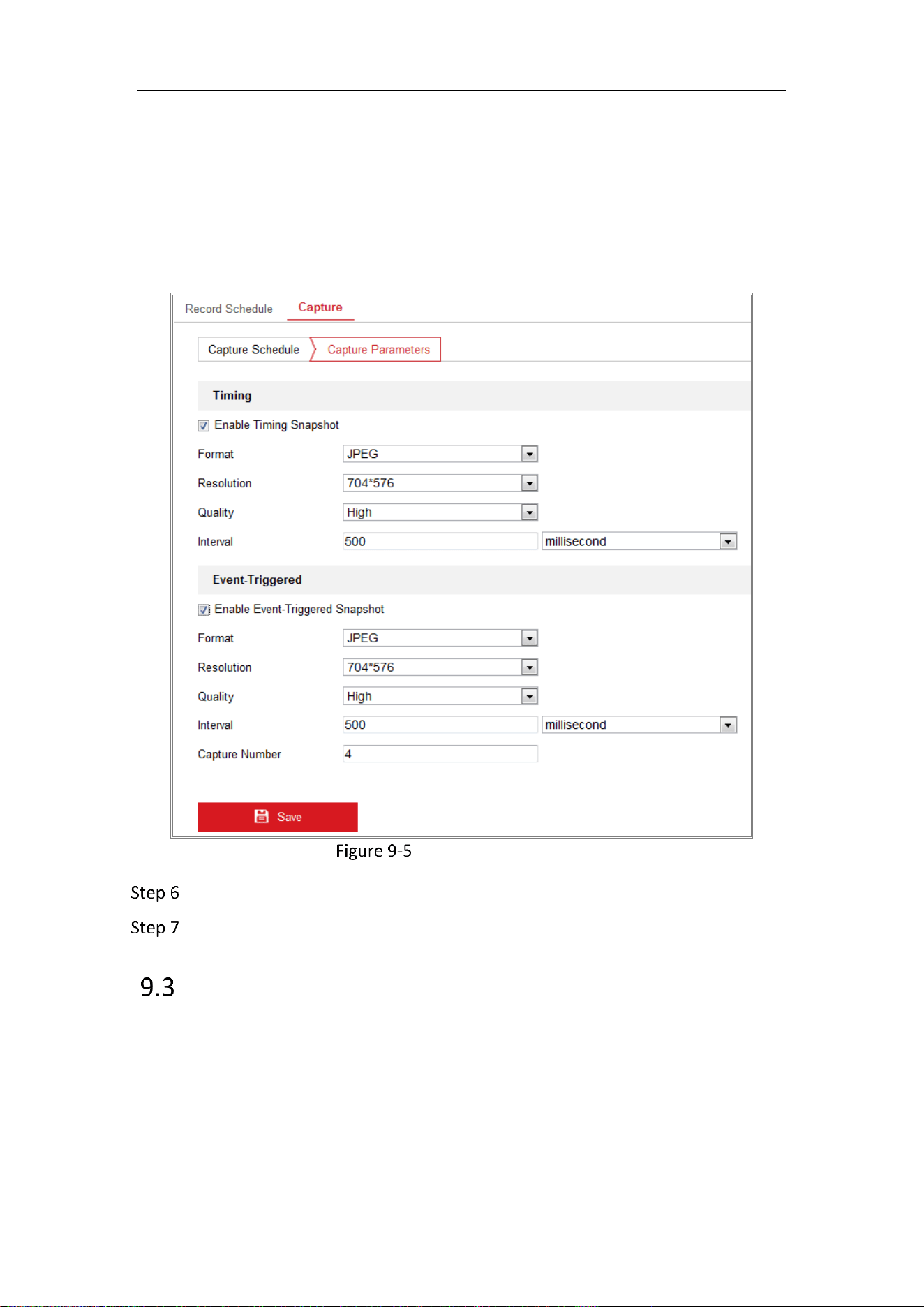
Mobile Network Camera • User Manual
99
1) Check the Enable Timing Snapshot checkbox to enable continuous
snapshot.
2) Select the picture format, resolution, quality and capture interval.
3) Check the Enable Event-triggered Snapshot checkbox to enable event-
triggered snapshot.
4) Select the picture format, resolution, quality, capture interval, and capture
number.
Set Capture Parameters
Set the time interval between two snapshots.
Click Save to save the settings.
Storage Management
Before you start:
The network disk should be available within the network and properly configured to
store the recorded files, log files, pictures, etc.
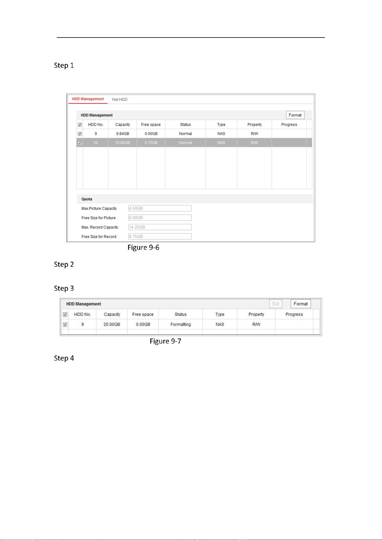
Mobile Network Camera • User Manual
100
Steps:
Go to Configuration > Storage > Storage Management > HDD Management, in
which you can view the capacity, free space, status, type and property of the
disk.
Storage Management Interface
If the status of the disk is Uninitialized, check the corresponding checkbox to
select the disk and click Format to start initializing the disk.
When the initialization completed, the status of disk will become Normal.
View Disk Status
Define the quota for record and pictures.
1) Input the quota percentage for picture and for record.
2) Click Save and refresh the browser page to activate the settings.

Mobile Network Camera • User Manual
101
Quota Settings
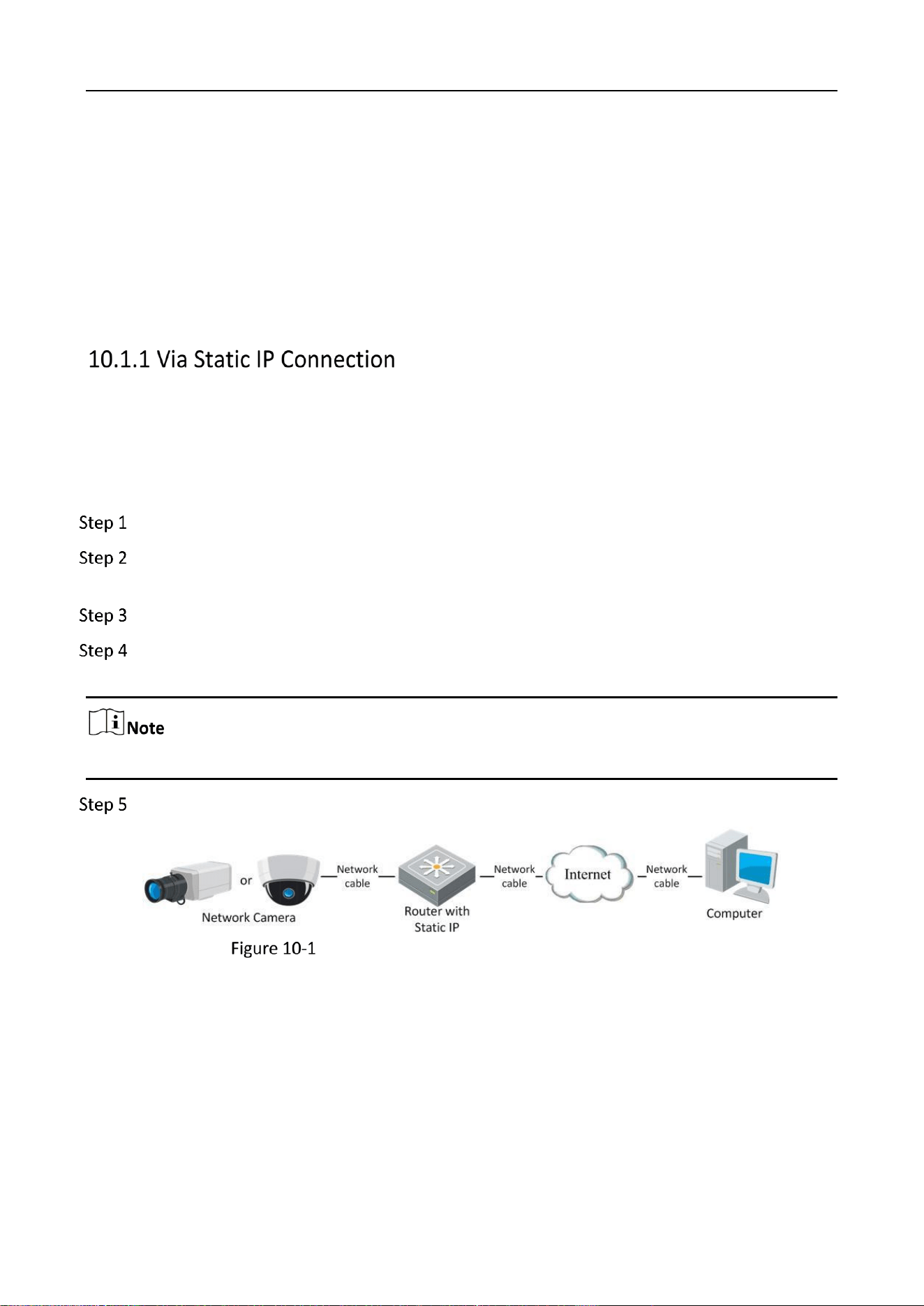
Mobile Network Camera • User Manual
102
Chapter 10 Access to the Network Camera
Purpose:
This section explains how to connect the network camera to the WAN with a static IP or a dynamic
IP.
Before you start:
Please apply a static IP from an ISP (Internet Service Provider). With the static IP address, you can
connect the network camera via a router or connect it to the WAN directly.
Connecting the network camera via a router
Connect the network camera to the router.
Assign a LAN IP address, the subnet mask and the gateway. Refer to Section 5.1.1 TCP/IP for
detailed IP address configuration of the network camera.
Save the static IP in the router.
Set port mapping, e.g., 80, 8000, and 554 ports. The steps for port mapping vary according to
the different routers. Please call the router manufacturer for assistance with port mapping.
Refer to Appendix 2 for detailed information about port mapping.
Visit the network camera through a web browser or the client software over the internet.
Accessing the Camera through Router with Static IP
Connecting the network camera with static IP directly
You can also save the static IP in the camera and directly connect it to the internet without using a
router. Refer to Section 5.1.1 TCP/IP for detailed IP address configuration of the network camera.
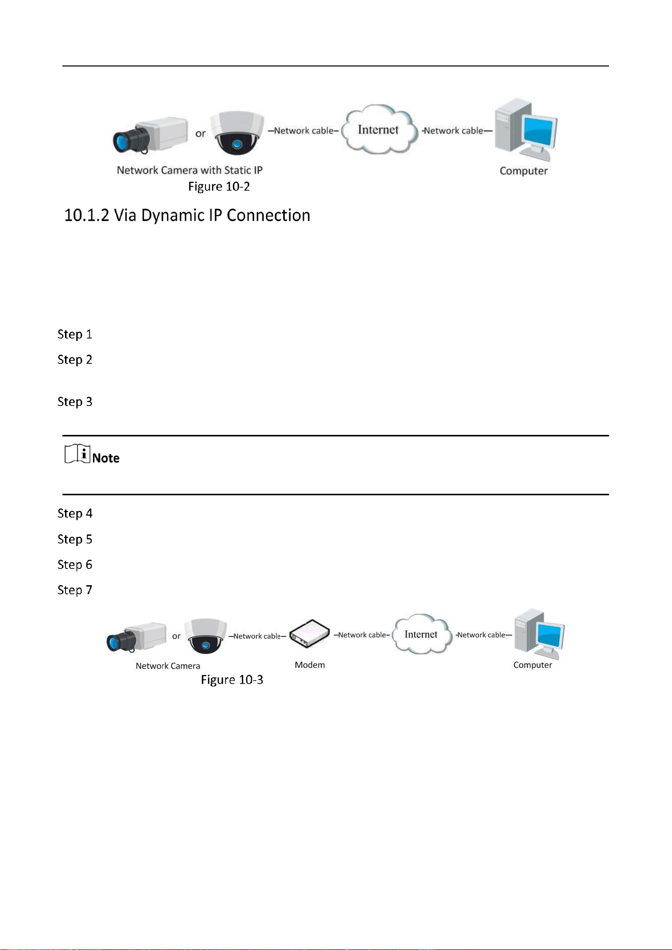
Mobile Network Camera • User Manual
103
Accessing the Camera with Static IP Directly
Before you start:
Please apply a dynamic IP from an ISP. With the dynamic IP address, you can connect the network
camera to a modem or a router.
Connecting the network camera via a router
Connect the network camera to the router.
In the camera, assign a LAN IP address, the subnet mask and the gateway. Refer to Section
2.1.2 for detailed IP address configuration of the network camera.
Set port mapping. E.g. 80, 8000, and 554 ports. The steps for port mapping vary depending on
different routers. Please call the router manufacturer for assistance with port mapping.
Refer to Appendix 2 for detailed information about port mapping.
Apply a domain name from a domain name provider.
Configure the DDNS settings in the setting interface of the router.
Visit the camera via the applied domain name.
Connecting the network camera via a modem
Accessing the Camera with Dynamic IP
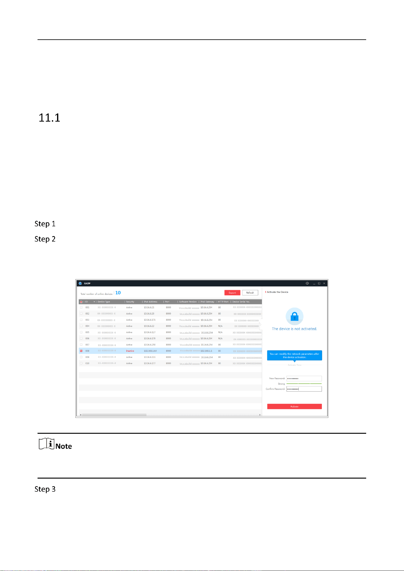
Mobile Network Camera • User Manual
104
Chapter 11 Appendix
Appendix 1 SADP Software Introduction
Description of SADP
SADP (Search Active Devices Protocol) is a kind of user-friendly and installation-free online device
search tool. It searches the active online devices within your subnet and displays the information of
the devices. You can also modify the basic network information of the devices using this software.
Search active devices online
Search online devices automatically
After launch the SADP software, it automatically searches the online devices every 15 seconds
from the subnet where your computer locates. It displays the total number and information
of the searched devices in the Online Devices interface. Device information including the
device type, IP address and port number, etc. will be displayed.
Figure A.1.1 Searching Online Devices
Device can be searched and displayed in the list in 15 seconds after it went online; it will be
removed from the list in 45 seconds after it went offline.
Search online devices manually
Mobile Network Camera • User Manual
105
You can also click to refresh the online device list manually. The newly searched
devices will be added to the list.
You can click or on each column heading to order the information; you can
click to expand the device table and hide the network parameter panel on the right side,
or click to show the network parameter panel.
Modify network parameters
Select the device to be modified in the device list and the network parameters of the device
will be displayed in the Modify Network Parameters panel on the right side.
Edit the modifiable network parameters, e.g. IP address and port number.
Enter the password of the admin account of the device in the Admin Password field and click
to save the changes.
STRONG PASSWORD RECOMMENDED
We highly recommend you create a strong password of your own choosing (using a minimum
of 8 characters, including at least three of the following categories: upper case letters, lower
case letters, numbers, and special characters) in order to increase the security of your product.
And we recommend you reset your password regularly, especially in the high security system,
resetting the password monthly or weekly can better protect your product.
Proper configuration of all passwords and other security settings is the responsibility of the
installer and/or end-user.
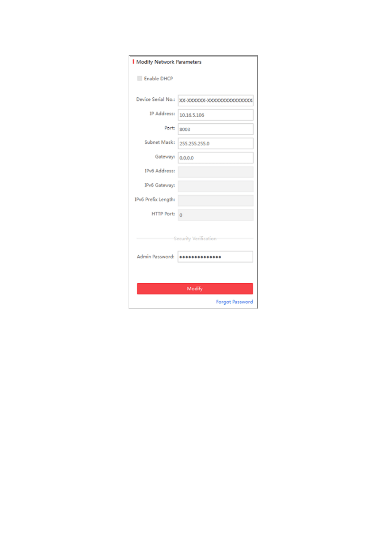
Mobile Network Camera • User Manual
106
Figure A.1.2 Modify Network Parameters
Mobile Network Camera • User Manual
107
Appendix 2 Device APP
Device Communication Matrix
Scan the following QR code to get device communication matrix.
Note that the matrix contains all communication ports of Hikvision network cameras.
Device Communication Matrix
Device Command
Scan the following QR code to get device common serial port commands.
Note that the command list contains the commonly used serial port commands for all Hikvision network
cameras.
device common serial port commands

0
UD Number
