USER'S MANUAL
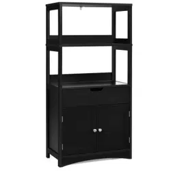
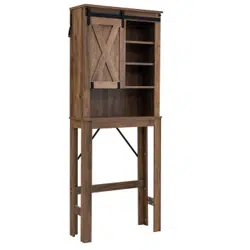
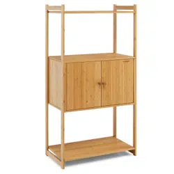
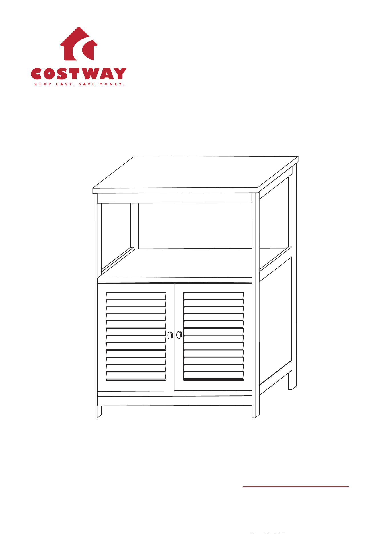
Bathroom Cabinet
G
M
N
Q
R
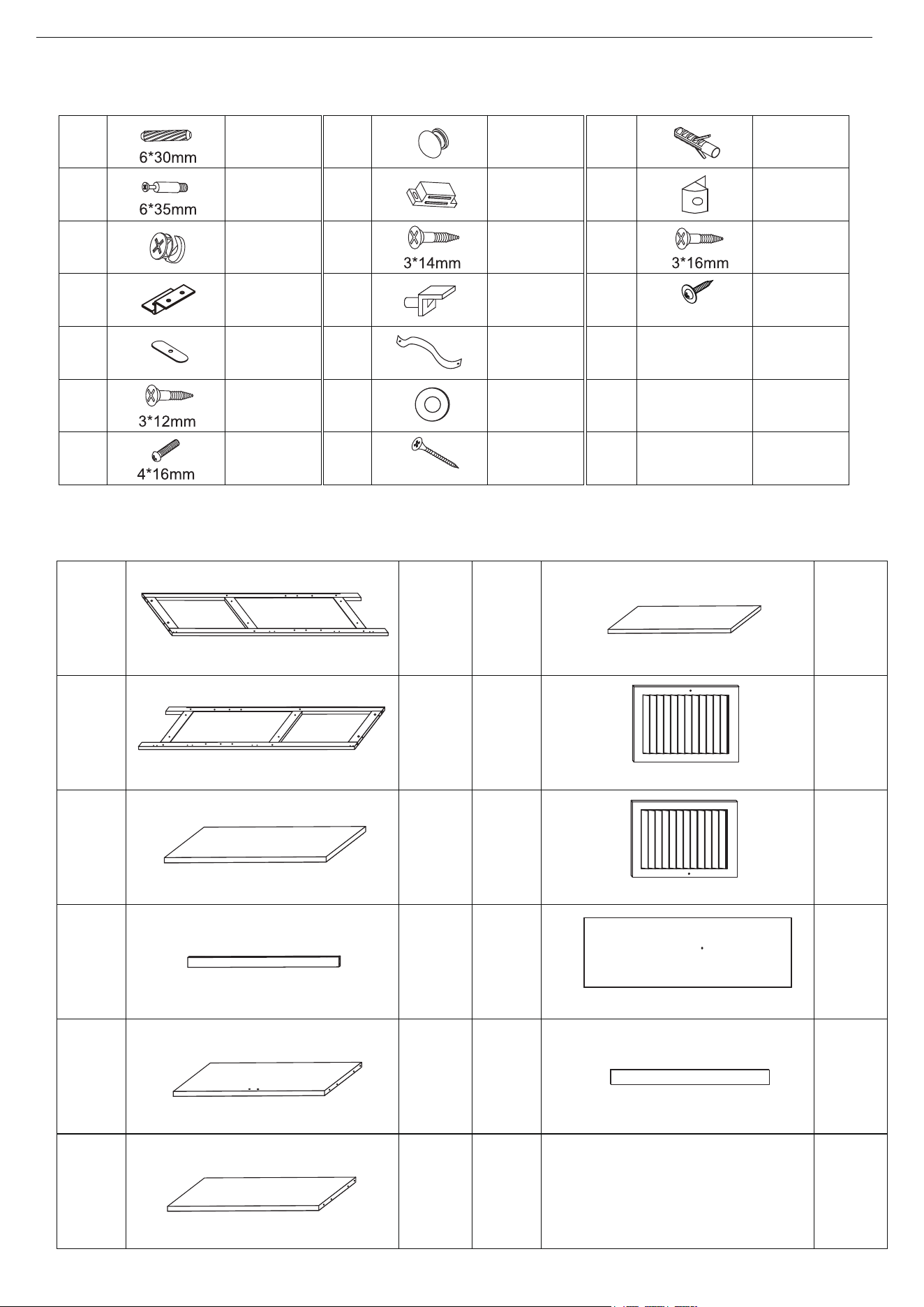
16 pcs
16 pcs
4 pcs
2 pcs
18 pcs
2 pcs
1 pc
8 pcs
8 pcs
2 pcs
2 pcs
3 pcs
1 pc
4 pcs
1 pc
2 pcs
7 pcs
PRODUCT ASSEMBLY
C
1 pc
7
2
9
3
10
4
11
5
6
D
E
F
H
I
J
K
L
O
P
8
1 pc
1 pc
2 pcs
1 pc
1 pc
1 pc
1 pc
1 pc
2 pcs
1 pc
1
1/8
Hardware List
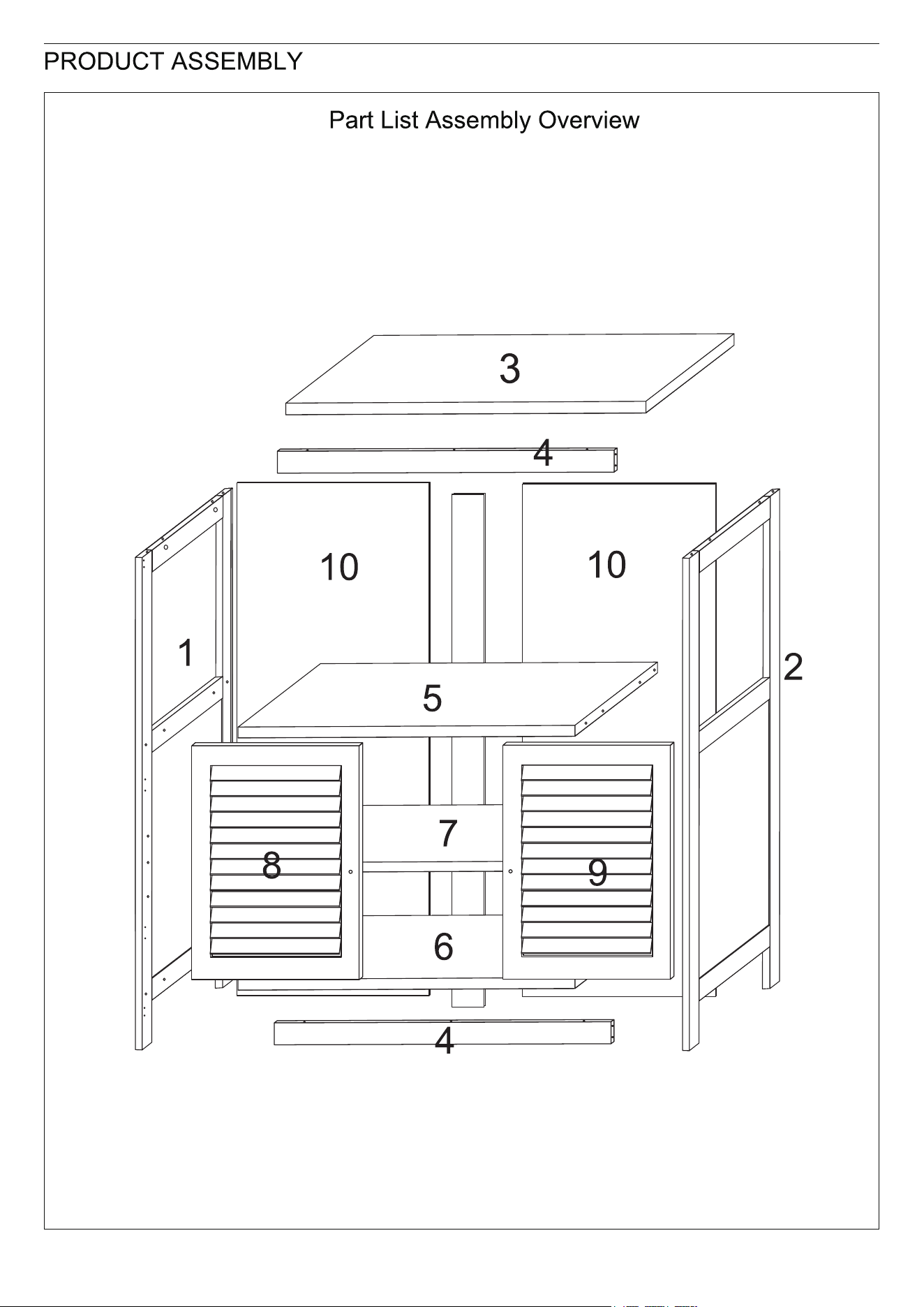
Parts List
16 pcs
A
B
2.5*10mm
4*40mm
Left Panel
Right Panel
Top Panel
Connect Bar
Fixed Shelf
Bottom Shelf
Adjustable Shelf
Left Door
Right Door
Back Panel
Back Connect Bar
11
2/8
3/8
2 pcs
D
E
F
H
5 pcs
1 pc
1 pc
G
1 pc
2 pcs
D
E
F
H
5 pcs
1 pc
1 pc
G
1 pc
D
F
E
8
H
G
F
F
D
9
8
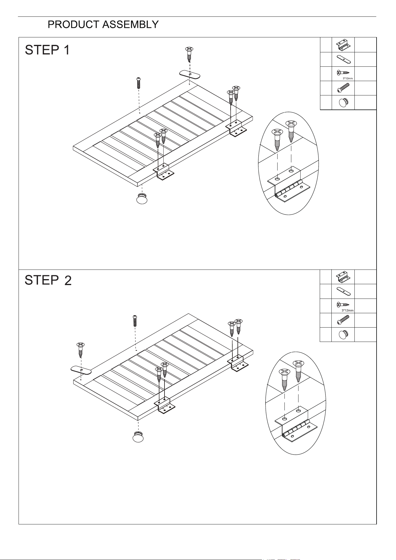
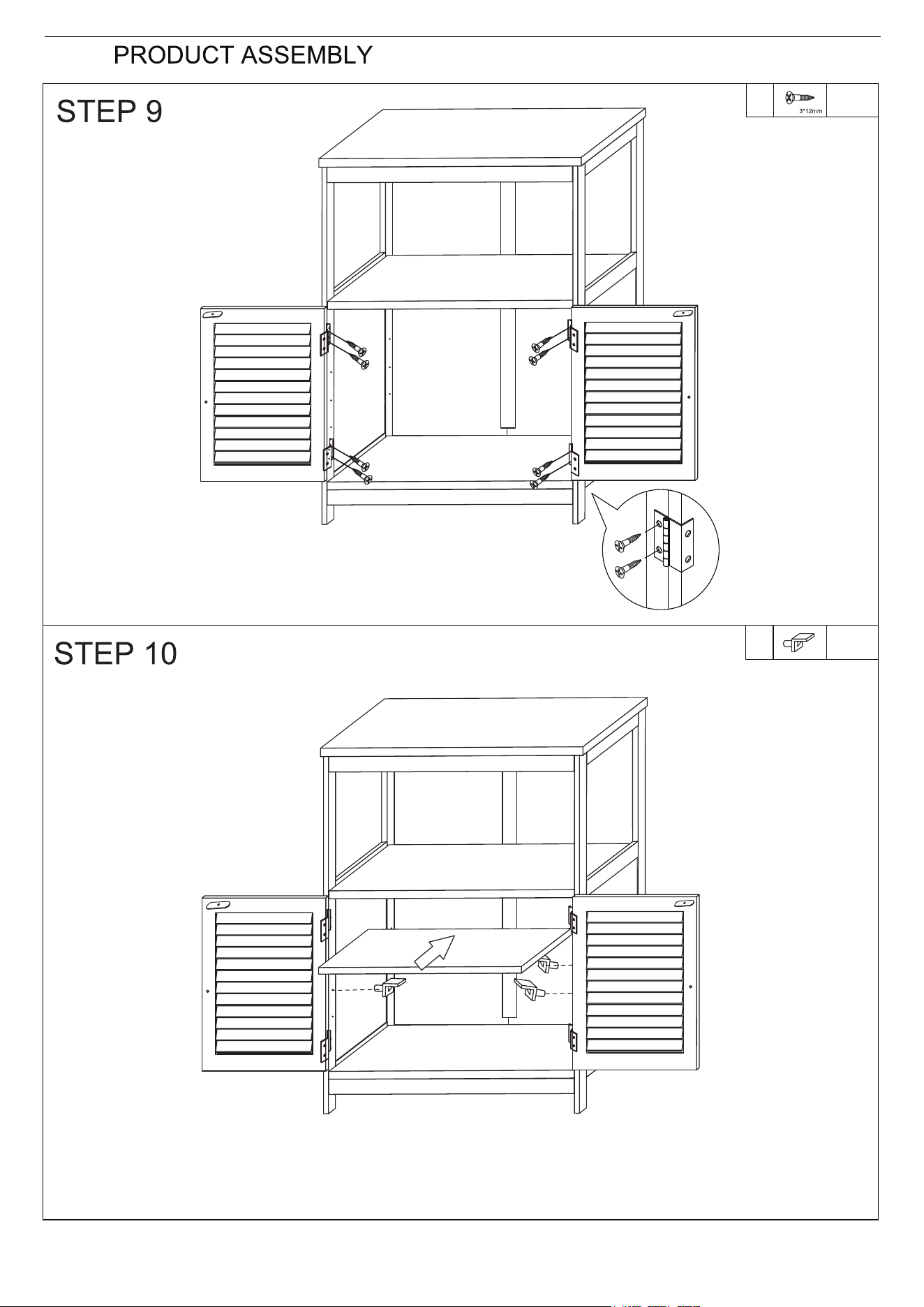
a) Attach Hinge (D) and Magnetic Bar (E) to Left Door (8) using Screw (F) as shown.
b) Attach Knob (H) to Door using Bolt (G).
9
F
F
D
E
G
H
F
D
9
9
a) Attach Hinge (D) and Magnetic Bar (E) to Right Door (9) using Screw (F) as shown.
b) Attach Knob (H) to Door using Bolt (G).
4
6
N
4/8
N
3 pcs
A
C
6 pcs
6 pcs
6 pcs
B
6
5
4
C
B
A
Turn
cam-lock
clockwise
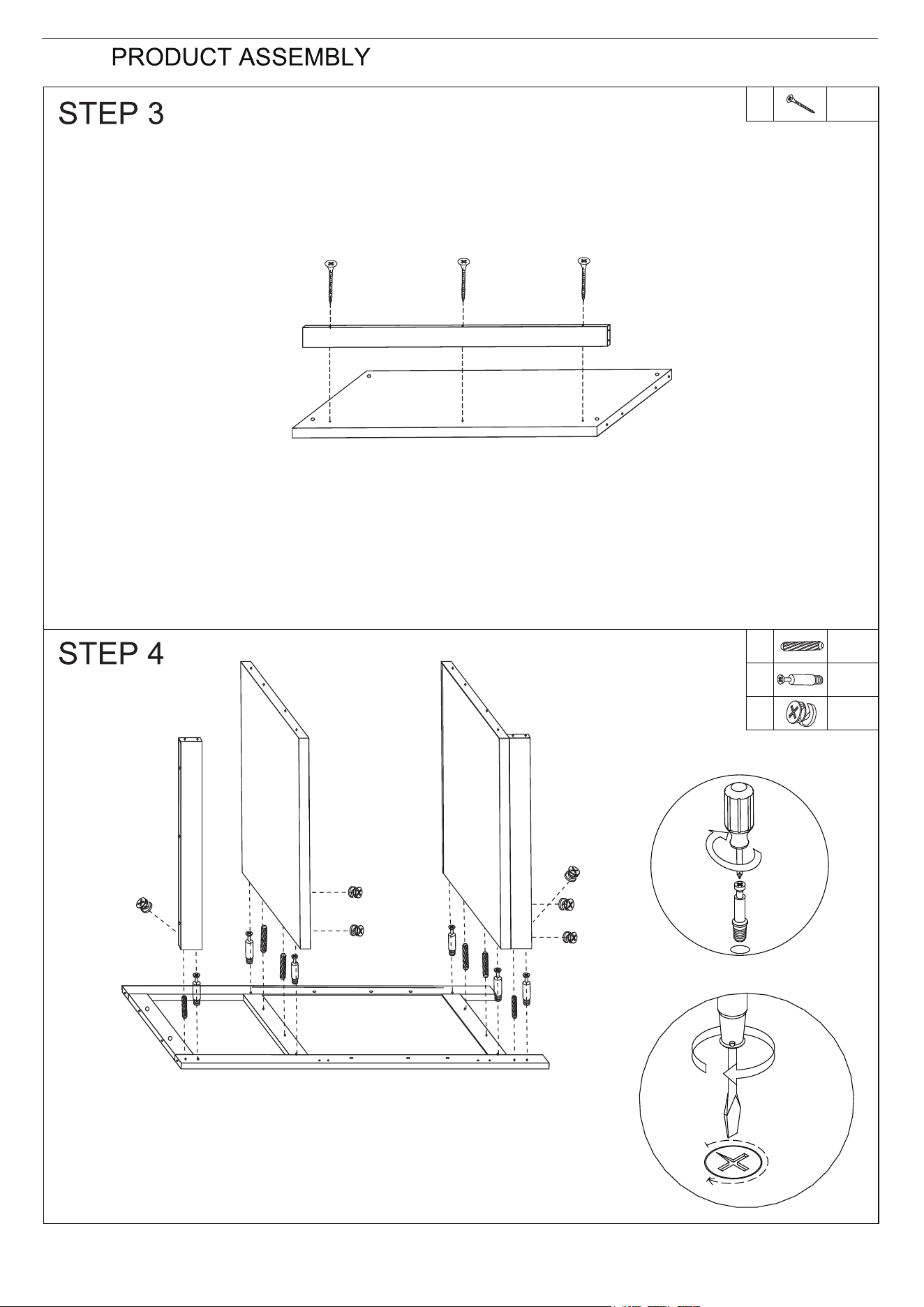
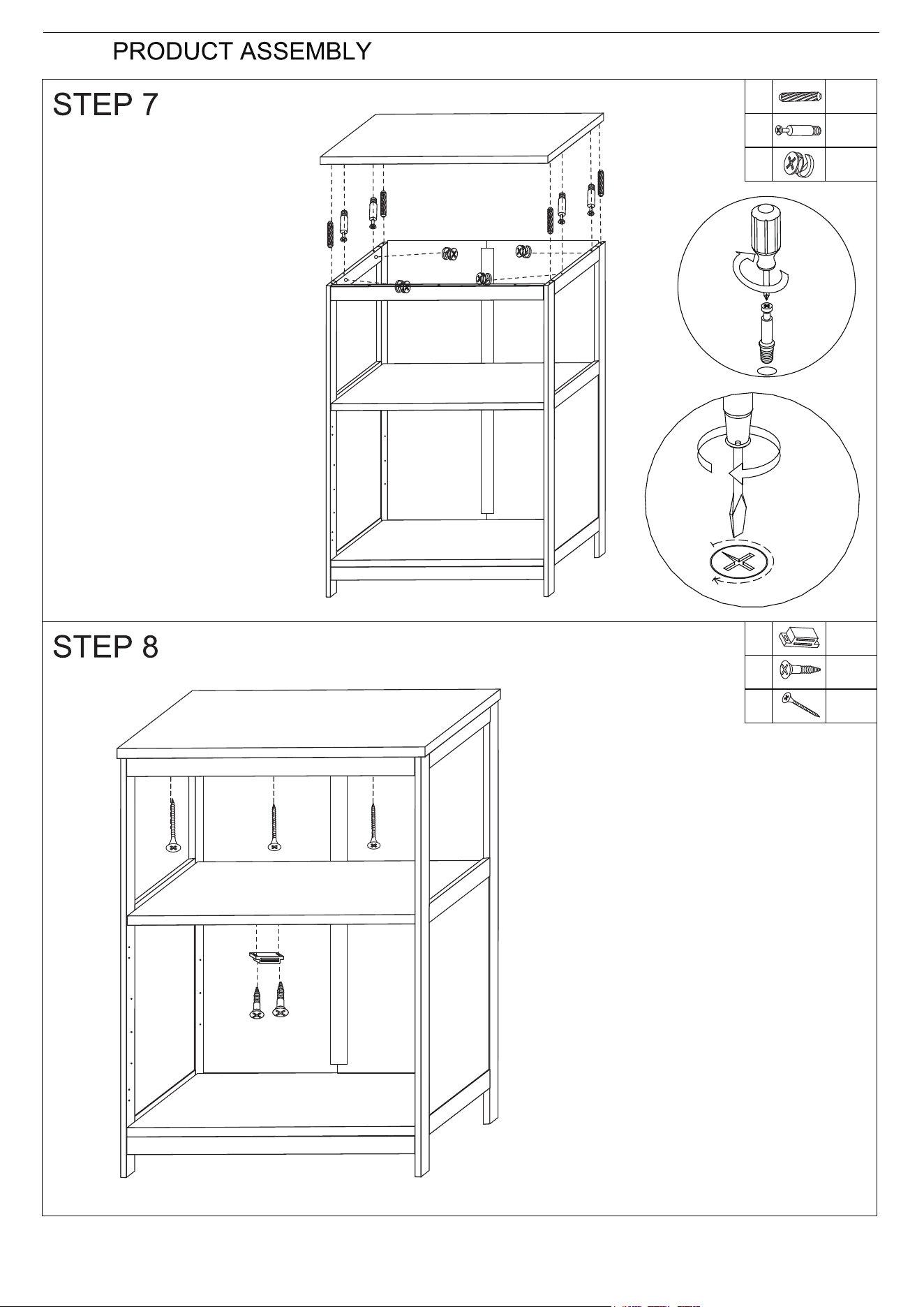
Attach Connect Bar (4) to Bottom Shelf (6) using Screw (N).
a) Screw Cam-bolt (B) into the pre-drilled holes on Left Panel
(1).
b) Attach Connect Bar (4), Fixed Shelf (5) and Bottom Shelf (6)
to (1) via Wood Dowel (A) and Cam-bolts on (1).
c) Insert Cam-lock (C) and turn it clockwise to lock onto Cam-bolt.
1
2
A
B
C
10
11
5/8
A
C
6 pcs
6 pcs
6 pcs
B
10
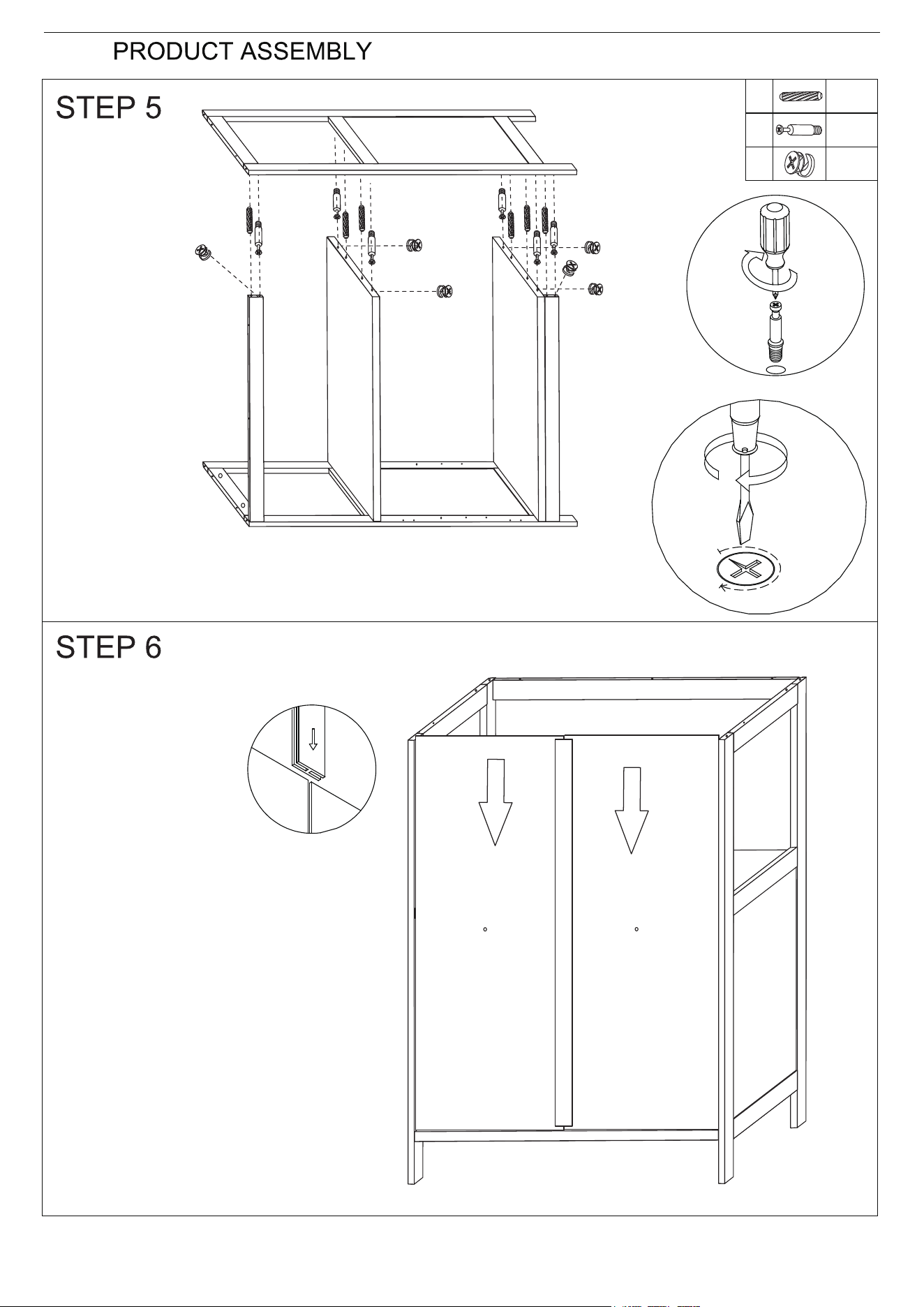
b) Attach (2) to (4, 5 & 6) via Wood Dowel (A) and Cam-bolts
on (2).
c) Insert Cam-lock (C) and turn it clockwise to lock onto Cam-bolt.
a) Screw Cam-bolt
(B) into the
pre-drilled holes
on Right Panel
(2).
6
5
4
4
Turn
cam-lock
clockwise
11
10
10
a) Slide in the Back Panel (10) via the
groove on Side Panel and Bottom
Shelf.
b) Slide in Back Connect Bar (11)
between two Back Panels.
C
3
N
I
J
6/8
A
B
A
C
4 pcs
4 pcs
4 pcs
B
Turn
cam-lock
clockwise
I
N
1 pc
2 pcs
3 pcs
J
3*14mm
a) Screw Cam-bolt (B) into
the pre-drilled holes on
Top Panel (3).
b) Attach (3) to (1 & 2) via
Wood Dowel (A) and
Cam-bolts on (3).
c) Insert Cam-lock (C) and
turn it clockwise to lock
onto Cam-bolt.
a) Affix Connect Bar (4) to Top Panel
(3) using Screw (N).
b) Attach Magnetic Catch (I) to Fixed
Shelf (5) using Screw (J).
1
2
3
4
5
K
7
7/8
F
8 pcs
F
4 pcs
F
8 9
D
F
Attach Door (8 & 9) to Side Panels (1 & 2) using Screw (F)
and hinge on Door.
1
2
Insert Shelf Pin (F) into the pre-drilled hole on Side Panels and place Adjustable Shelf
(7) on it.
11
12
J
M
L
O
M
N
Q
P
R
8/8
8 pcs
P
Q
R
2 pcs
8 pcs
3*16mm
Q
P
J
M
1 pc
1 pc
2 pcs
L
O
1 pc
1 pc
N
3*14mm
WALL
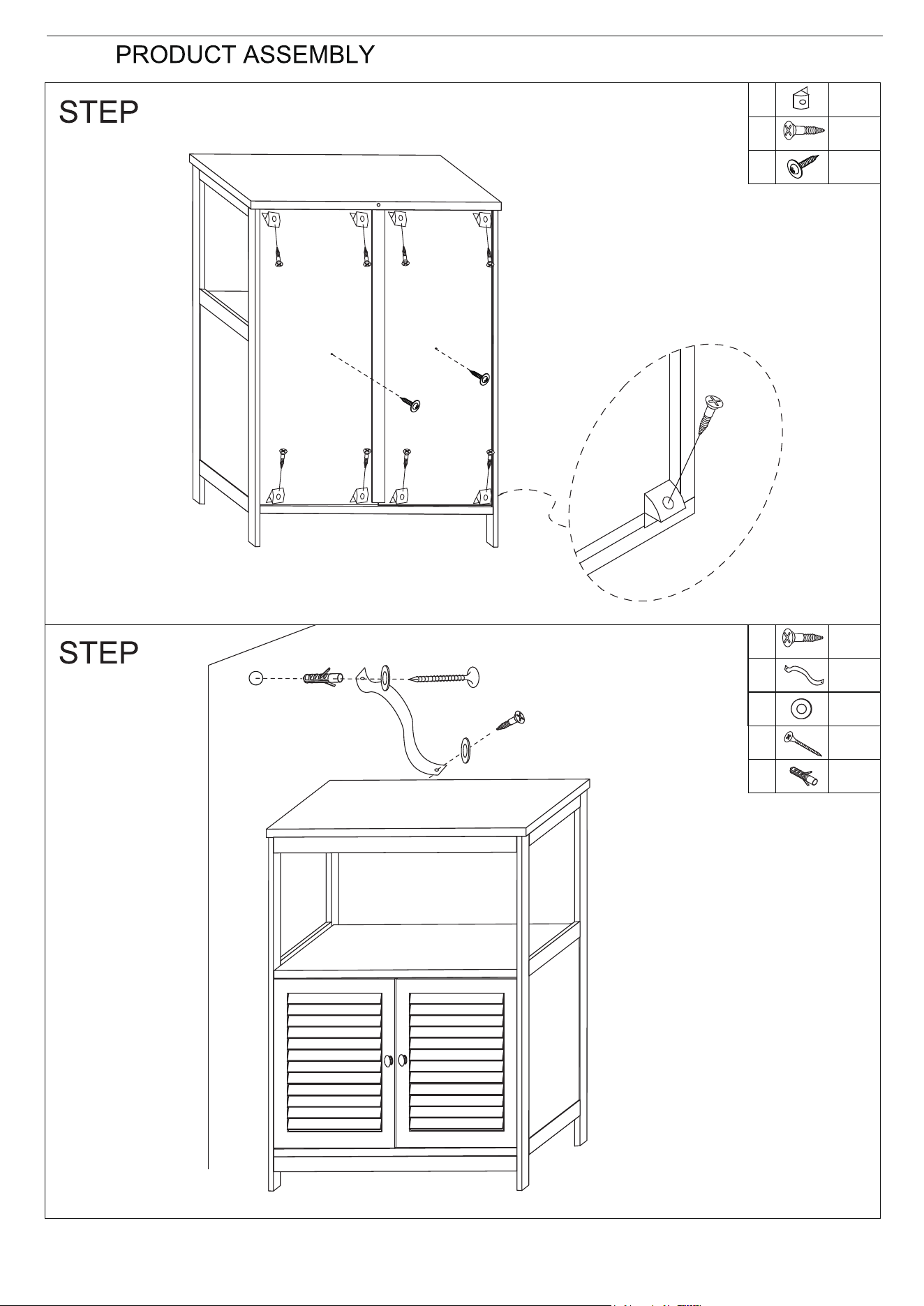
a) Attach Fixed Button (P) to the
groove for back panel by using
Screw (Q) as shown.
b) Affix Back panel to Fixed Shelf using
Screw (R).
a) Attach Bandage (L) to Top
Panel using Flat Washer
(M) and Screw (J).
b) Drill a hole (as per diameter
of Plastic Anchor ) in the
drywall.
c) Insert Plastic Anchor (O)
into the drywall.
d) Fixed the product to the
drywall using Flat Washer
(M) and Screw (N).
1