Standby Power Rating
HG04845 – (Aluminium, Dark Gray) – 48 kW 60 Hz
HG06045 – (Aluminium, Dark Gray) – 60 kW 60 Hz
HG08045 – (Aluminium, Dark Gray) – 80 kW 60 Hz
INCLUDES
• Innovative engine design and rigorous testing: Total commitment to
component testing, reliability testing, destruction and life testing, plus testing
to applicable CSA, NEMA, EGSA, and other standards allows users to choose
Honeywell generators with the confidence that these systems will provide
superior performance.
• PrecisionPower
TM
Electrical Technology: Superior harmonics and sine wave
form produce less than 5% Total Harmonic Distortion for utility quality power.
This allows confident operation of sensitive electronic and microchip based
appliances, such as variable speed HVAC.
• Solid-State, Frequency Compensated Voltage Regulation: This state-of-the-
art, power maximizing regulation system is the standard on all Honeywell models.
It provides optimized FAST RESPONSE to changing load conditions and
MAXIMUM MOTOR STARTING CAPABILITY by electronically torque-matching
the surge loads to the engine. Provides precise digital voltage regulation for
sensitive electronics.
• Single Source Service Response: Our extensive dealer network provides parts
and service know-how for the entire unit, from the engine to the smallest
electrical component.
• Honeywell Transfer Switches: The Honeywell generator line is offered with its
own transfer systems and controls for total system compatibility.
• Mobile Link® Wi-Fi Connectivity: Honeywell standby generators are Wi-Fi
enabled. Now users can remotely connect and monitor generator status on a
smartphone, tablet, or PC from anywhere in the world using Mobile Link's
free service
• 18 in (457 mm) Offset: Listed and labeled by the Southwest Research Institute
allowing installation as close as 18 in (457 mm) to a structure.
**Must be located away from doors, windows, and fresh air intakes and in
accordance with local codes.
• PrecisionPower™
Electrical Technology
• Two-line multilingual
digital LCD controller
(English, Spanish,
French, Portuguese)
• Isochronous
electronic governor
• UV/Ozone resistant
hoses
• System and status &
maintenance interval
LED indicators
• Closed coolant
recovery system
• Voltage regulation
designed for sensitive
electronics
• Electronic engine
control module
• Smart battery charger
• Sound attenuated
aluminum enclosure
• UL 2200 Listed
• Natural Gas (NG) or
Liquid Propane (LP)
Gas operation
• 5 Year premium
limited warranty
• Field convertible fuel
type with no
mechanical
adjustment required
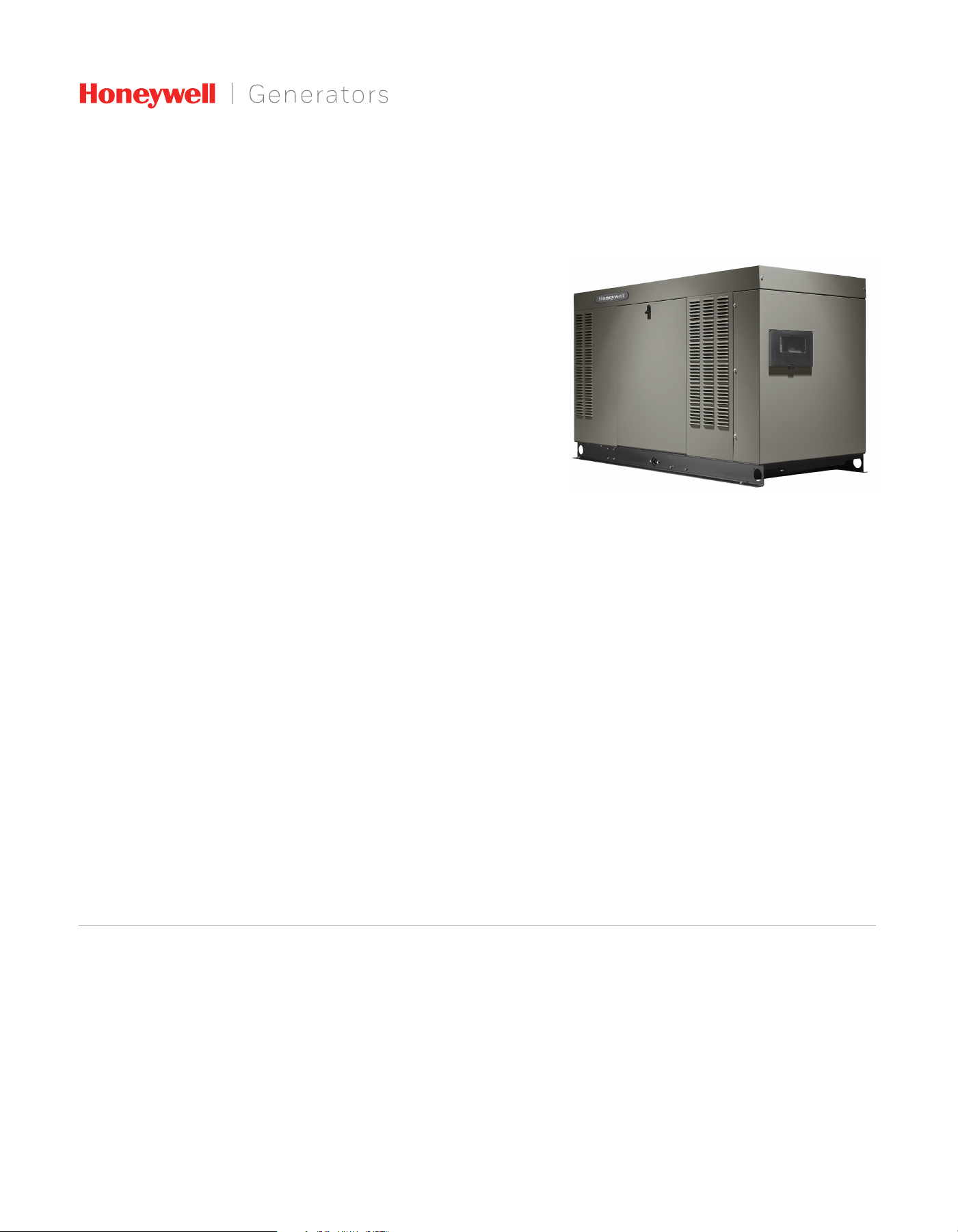
FEATURES & BENEFITS
48 / 60 / 80 kW Liquid-Cooled Generator Sets

48 / 60 / 80 kW Technical Specifications
GENERATOR SPECIFICATIONS 48 KW 60 / 80 KW
Type Synchronous
Rotor insulation class F H
Stator insulation class H
Telephone Interference Factor (TIF) <50
Alternator output leads 1-Phase 4 wire
Alternator output leads 3-Phase 6 wire
Bearings Sealed ball
Coupling Flexible disc
Excitation system Direct
VOLTAGE REGULATION
Type Electronic
Sensing Single-phase
Regulation Designed for sensitive electronics
GOVERNOR SPECIFICATIONS
Type Electronic
Frequency regulation Isochronous
Steady state regulation Designed for sensitive electronics
ELECTRICAL SYSTEM
Battery charge alternator 12 volt 30 amp
Static battery charger 2.5 amp
Recommended battery Group 27F, 725CCA
System voltage (battery not
included)
12 volts
GENERATOR FEATURES
Revolving field heavy duty generator
Directly connected to the engine
Operating temperature rise 248 °F (120 °C) above a 104 °F (40 °C) ambient
Class H insulation is NEMA rated
Class F insulation is NEMA rated
All models fully prototype tested
ENCLOSURE FEATURES
Aluminum weather protective
enclosure
Provides protection against mother nature.
Electrostatically applied textured epoxy paint for
added durability.
Enclosed critical grade muffler
Quiet, critical grade muffler is mounted inside the
unit to prevent injuries.
Small, compact, attractive Makes for an easy, eye appealing installation.
SAE
Sound attenuated enclosure ensures quiet
operation.
ENGINE SPECIFICATIONS 48 KW 60 / 80 KW
Make Generac
Type In-line
Cylinders 4
Displacement (L) 4.5
Bore (in / mm) 4.5 / 114.3
Stroke (in / mm) 4.25 / 107.95
Compression ratio 9.9:1 8.85:1
Intake air system
Naturally aspirated Turbocharged and
aftercooled
Lifter type Hydraulic
ENGINE LUBRICATION SYSTEM
Oil pump type Gear
Oil filter type Full flow spin-on cartridge
Crankcase capacity (qt / L) 11.6 / 11
ENGINE COOLING SYSTEM
Type Closed
Water pump Belt driven
Fan speed (rpm) 2,100
Fan diameter (in / cm) 20 / 50.8
Fan mode Pusher
FUEL SYSTEM
Fuel type Natural gas, propane vapor
Fuel shut off solenoid Standard
NG operating fuel pressure 3.5–14 in water column / 0.87–3.48 kPa
LP operating fuel pressure 7–14 in water column / 1.74–3.48 kPa

KW LPG AMP LPG KW NATURAL GAS AMP NATURAL GAS CB SIZE (BOTH)
HG04845
120/240 V, 1Ø, 1.0 pf 48 200 48 200 200
120/208 V, 3Ø, 0.8 pf 48 167 48 167 175
120/240 V, 3Ø, 0.8 pf 48 144 48 144 150
277/480 V, 3Ø, 0.8 pf 48 72 48 72 80
HG06045
120/240 V, 1Ø, 1.0 pf 60 250 60 250 300
120/208 V, 3Ø, 0.8 pf 60 208 60 208 200
120/240 V, 3Ø, 0.8 pf 60 180 60 180 200
277/480 V, 3Ø, 0.8 pf 60 90 60 90 100
HG08045
120/240 V, 1Ø, 1.0 pf 75 312 80 333 400
120/208 V, 3Ø, 0.8 pf 75 260 80 277 300
120/240 V, 3Ø, 0.8 pf 75 226 80 240 300
277/480 V, 3Ø, 0.8 pf 75 113 80 120 150
GENERATOR OUTPUT VOLTAGE/KW – 60 HZ
Voltage Dip @ < 0.4 pf
15% 30%
HG04845
120/240 V, 1Ø 100 300
120/208 V, 3Ø 118 242
120/240 V, 3Ø 145 260
277/480 V, 3Ø 64 123
HG06045
120/240 V, 1Ø 150 413
120/208 V, 3Ø 135 313
120/240 V, 3Ø 117 289
277/480 V, 3Ø 54 122
HG08045
120/240 V, 1Ø 283 600
120/208 V, 3Ø 236 500
120/240 V, 3Ø 204 432
277/480 V, 3Ø 102 192
SURGE CAPACITY IN AMPS
Natural Gas Propane
(ft
3
/hr) (m
3
/hr) (gal/hr) (ft
3
/hr) (L/hr)
HG04845
Exercise cycle
101 2.86 0.67 24.5 2.54
25% of rated load
201 5.7 2.88 104.7 10.9
50% of rated load
336 9.5 4.16 151.3 15.7
75% of rated load
447 12.7 5.28 192 20
100% of rated load
604 17.1 6.61 240.4 25
HG06045
Exercise cycle
103 2.9 0.9 33.2 3.5
25% of rated load
257 7.3 2.1 78 8.1
50% of rated load
432 12.2 4.4 161.2 16.8
75% of rated load
618 17.5 6.8 247.2 25.7
100% of rated load
808 22.9 8.4 305.6 31.8
HG08045
Exercise cycle
103 2.9 0.9 33.2 3.5
25% of rated load
292 8.3 2.6 93.6 9.7
50% of rated load
534 15.1 5.7 208.8 21.7
75% of rated load
799 22.6 8.3 303.2 31.5
100% of rated load
1063 30.1 10.8 393.2 40.9
ENGINE FUEL CONSUMPTION
Note: Fuel pipe must be sized for full load.
For BTU content, multiply ft³/hr x 2,520 (LP) or ft³/hr x 1,000 (NG)
For megajoule content, multiply m³/hr x 93.15 (LP) or m³/hr x 37.26 (NG)
See "Emissions Data Sheets" for maximum fuel flow for EPA and SCAQMD permitting
purposes.
STANDBY RATING: Standby ratings apply to installations served by a reliable utility source.
The standby rating is applicable to varying loads for the duration of a power outage. There
is no overload capability for this rating. Ratings are in accordance with ISO-3046-1. Design
and specifications are subject to change without notice.
48 / 60 / 80 kW Operating Data

MODEL 48 KW 60 / 80 KW
Air flow (inlet air including alternator and combustion air in cfm / cmm) 2829 / 80.1 3197 / 90.5
System coolant capacity (gal / L) 2.9 / 11 4.5 / 17
Heat rejection to coolant (BTU per hr / MJ per hr) 201,060 / 212 204,570
Maximum operation air temperature on radiator (°F / °C) 150 / 66
Maximum ambient temperature (°F / °C) 140 / 60
Flow at rated power (scfm / cmm) 92.7 / 2.6 170.4 / 4.8
Sound output in dB(A) at 23 ft (7 m)* 68 68
*Sound levels are measured in exercise mode and from the front of the generator. Sound levels taken from other sides of the generator may be higher depending on installation parameters.
Exhaust flow at rated output (scfm / cmm) 104 / 2.9 181 / 5.1
Exhaust temperature at muffler outlet (°F / °C) 945 / 507 1213 / 656
Rated synchronous rpm 1,800
ENGINE COOLING
COMBUSTION REQUIREMENTS
SOUND EMISSIONS
EXHAUST
ENGINE PARAMETERS
POWER ADJUSTMENT FOR AMBIENT CONDITIONS
Temperature deration ........................................................................................................................................................ 1.65% for every 10 °F above 77 °F or 3% for every 10 °C above 25 °C
Altitude deration ..............................................................................................................................................................3% for every 1,000 ft above 600 ft or 1% for every 100 m above 183 m
Two-line plain text LCD................................................................................................................................................................................................................Simple user interface for ease of operation.
Mode buttons: AUTO ..................................................................................................................................................................................................... Automatic Start on Utility failure. 7 day exerciser.
OFF .............................................................................................................................................................................Stops unit. Power is removed. Control and charger still operate.
MANUAL ............................................................................................................................. Start with starter control, unit stays on. If utility fails, transfer to load takes place.
Programmable start delay between 2–1500 seconds ........................................................................................................................................5 sec standard (programmable by dealer only)
Engine start sequence .........................................................................................................................................................................Cyclic cranking: 16 sec on, 7 rest (90 sec maximum duration)
Engine warm-up
............................................................................................................................................................................................................................................................................................................5 sec
Engine cool-down ....................................................................................................................................................................................................................................................................................................... 1 min
Starter lock-out ......................................................................................................................................................................................Starter cannot re-engage until 5 sec after engine has stopped.
Smart battery charger .........................................................................................................................................................................................................................................................................................Standard
Automatic Voltage Regulation with Over and Under Voltage protection
....................................................................................................................................................................................Standard
Automatic Low Oil Pressure shutdown ........................................................................................................................................................................................................................................................Standard
Overspeed shutdown ........................................................................................................................................................................................................................................................................... Standard, 72 Hz
High Temperature shutdown ...........................................................................................................................................................................................................................................................................Standard
Overcrank protection
...........................................................................................................................................................................................................................................................................................Standard
Safety fused..............................................................................................................................................................................................................................................................................................................Standard
Failure to Transfer protection ...........................................................................................................................................................................................................................................................................Standard
Low Battery/Battery Problem protection and Battery Condition indication .............................................................................................................................................................................Standard
50 Event Run log
..................................................................................................................................................................................................................................................................................................Standard
Future set capable exerciser .............................................................................................................................................................................................................................................................................Standard
Incorrect wiring protection ................................................................................................................................................................................................................................................................................Standard
Internal fault protection
.....................................................................................................................................................................................................................................................................................Standard
Common external fault capability .................................................................................................................................................................................................................................................................Standard
Governor failure protection ...............................................................................................................................................................................................................................................................................Standard
Field upgradeable firmware
..............................................................................................................................................................................................................................................................................Standard
CONTROLLER FEATURES
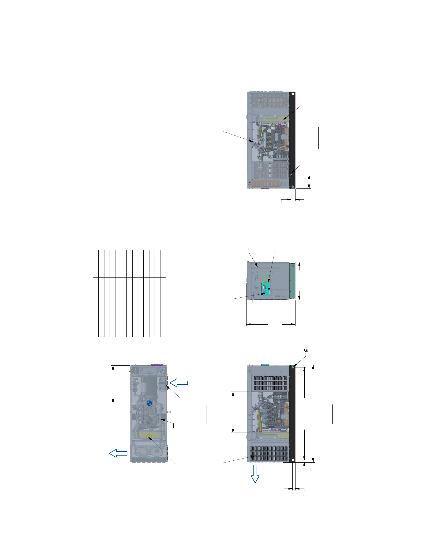
48 / 60 / 80 kW Operating Data
2119
[83.4]
OVERALL LENGTH
1212 [47.7]
DOOR TYP
888 [35.0]
OVERALL WIDTH
2026 [79.8] TYP
58
[2.3]
TYP
47
[1.8]
318
[12.5]
65
[2.6]
1168 [46.0]
OVERALL
HEIGHT
843 [33]
CENTER OF GRAVITY
(SEE NOTE 5)
WEIGHT DATA
ENGINE/KW
ENCLOSURE
MATERIAL
WEIGHT
GENSET ONLY
KG [LBS]
WEIGHT
SHIPPING SKID
KG [LBS]
SHIPPING WEIGHT
KG [LBS]
4.5L/48KW AL 808 [1781] 51 [112] 859 [1893]
SERVICE ITEM 4.5L
OIL FILL CAP LEFT SIDE
OIL DIP STICK LEFT SIDE
OIL FILTER LEFT SIDE
OIL DRAIN HOSE RIGHT SIDE
RADIATOR DRAIN HOSE RIGHT SIDE
COOLANT RECOVERY BOTTLE RIGHT SIDE
RADIATOR FILL CAP ROOF TOP
AIR CLEANER ELEMENT LEFT SIDE
SPARK PLUGS LEFT SIDE
MUFFLER SEE NOTE 11
DRIVE BELT EITHER SIDE
BATTERY LEFT SIDE
NOTES:
1. MINIMUM RECOMMENDED CONCRETE PAD SIZE IS 6" OFFSET OF OVERALL LENGTH
AND WIDTH OF GENERATOR. {1193.8 (47") WIDE X 2423.2 (95.4") LONG}. REFERENCE
INSTALLATION GUIDE SUPPLIED WITH THE UNIT FOR CONCRETE PAD GUIDELINES.
REFERENCE MANUFACTURER'S SPECIFICATIONS IF USING ENGINEERED, PREFABRICATED SLABS.
2. ALLOW SUFFICIENT ROOM ON ALL SIDES OF THE GENERATOR FOR MAINTENANCE
AND SERVICING. THIS UNIT MUST BE INSTALLED IN ACCORDANCE WITH CURRENT
APPLICABLE NFPA 37 AND NFPA 70 STANDARDS AS WELL AS ANY OTHER FEDERAL,
STATE, AND LOCAL CODES.
3. CONTROL PANEL / CIRCUIT BREAKER INFORMATION:
- SEE SPECIFICATION SHEET OR OWNERS MANUAL
- ACCESSIBLE THROUGH CUSTOMER ACCESS ASSEMBLY DOOR ON REAR OF GENERATOR.
4. REMOVE THE REAR ENCLOSURE COVER PANEL TO ACCESS
THE STUB-UP AREAS AS FOLLOWS:
- HIGH VOLTAGE CONNECTION INCLUDING AC LOAD LEAD CONDUIT CONNECTION
NEUTRAL CONNECTION, BATTERY CHARGER 120 VOLT AC (0.5 AMP MAX) CONNECTION.
- LOW VOLTAGE CONNECTION INCLUDING TRANSFER SWITCH CONTROL WIRES.
5. CENTER OF GRAVITY AND WEIGHT MAY CHANGE DUE TO UNIT OPTIONS.
6. BOTTOM OF GENERATOR SET MUST BE ENCLOSED TO PREVENT PEST INTRUSION AND
RECIRCULATION OF DISCHARGE AIR AND/OR IMPROPER COOLING AIR FLOW.
7. REFERENCE OWNERS MANUAL FOR LIFTING WARNINGS.
8. MOUNTING BOLTS OR STUDS TO MOUNTING SURFACE SHALL BE 5/8-11 GRADE 5
(USE STANDARD SAE TORQUE SPECS)
9. MUST ALLOW FREE FLOW OF INTAKE AIR, DISCHARGE AIR AND EXHAUST. SEE SPEC
SHEET FOR MINIMUM AIR FLOW AND MAXIMUM RESTRICTION REQUIREMENTS.
10. GENERATOR MUST BE INSTALLED SUCH THAT FRESH COOLING AIR IS AVAILABLE
AND THAT DISCHARGE AIR FROM RADIATOR IS NOT RECIRCULATED.
11. EXHAUST MUFFLER ENCLOSED WITHIN GENERATOR ENCLOSURE,
REMOVE FRONT PANEL TO ACCESS.
TOP VIEW
LEFT SIDE VIEW
REAR VIEW
RIGHT SIDE VIEW
RADIATOR/EXHAUST
DISCHARGE AIR
(BOTH SIDES)
AIR INTAKE
(BOTH SIDES)
REFERENCE OWNERS MANUAL
FOR PERIODIC REPLACEMENT
PARTS LIST
DIMENSIONS: MM [INCH]
EXHAUST MUFFLER
ENCLOSED WITHIN
GENERATOR ENCLOSURE
RADIATOR/EXHAUST
DISCHARGE AIR
CUSTOMER ACCESS
ASSEMBLY, CONTROL
PANEL ACCESS
BATTERY CHARGER
LOCATED WITHIN
SEE NOTE 4
REAR ENCLOSURE
COVER PANEL
SEE NOTE 4
CIRCUIT BREAKER
SEE NOTE 3
VICE ACTION LATCH
ONE PER DOOR
ONE LIFT OFF DOOR PER
SIDE OF GENERATOR
FUEL LINE CONNECTION
1-1/4" NPT FEMALE TEE
THROUGH BASEFRAME OPENING
REMOVE COVER
FOR ACCESS TO
RADIATOR FILL
CAP
BATTERY 12V
GROUP 27F
NEGATIVE GROUND
P/N G058665
Drawing A0000293718 Rev B (1 of 2)
48 kW Installation Layout
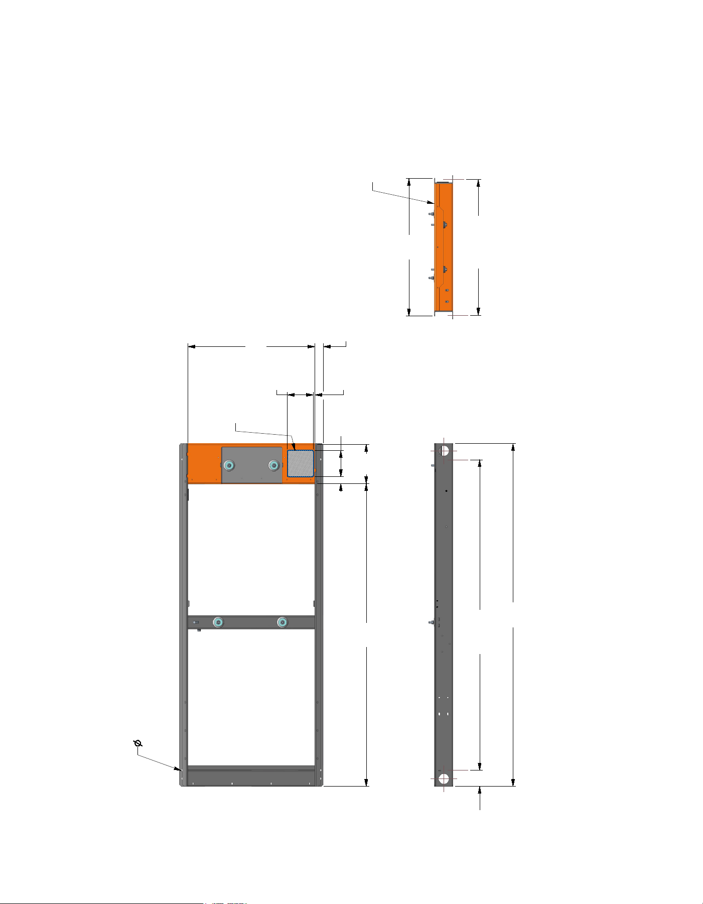
850
[33.5]
2119
[83.4]
1872
[73.7]
786
[30.9]
51
[2.0]
9
[.4]
42
[1.7]
162
[6.4]
STUB-UP
AREA
162
[6.4]
STUB-UP
AREA
243
[9.5]
100
[3.94]
1919 [75.5]
MOUNTING SLOT CENTERS
838.1 [33.00]
MOUNTING SLOT CENTERS
*NOTE:
STUB-UP AREA FOR HIGH AND LOW
VOLTAGE CONNECTIONS, CIRCUIT BREAKER,
NEUTRAL AND CUSTOMER CONNECTION OPENING.
DIMENSIONS: MM [INCH]
LEFT SIDE VIEW
13.5 X 29.5
[.53] [1.2]
MOUNTING SLOTS
4X
HIGH AND LOW
VOLTAGE
STUB-UP AREA
TOP VIEW
REMOVABLE
STUB-UP COVER
REAR VIEW
Drawing A0000293718 Rev B (2 of 2)
48 kW Installation Layout
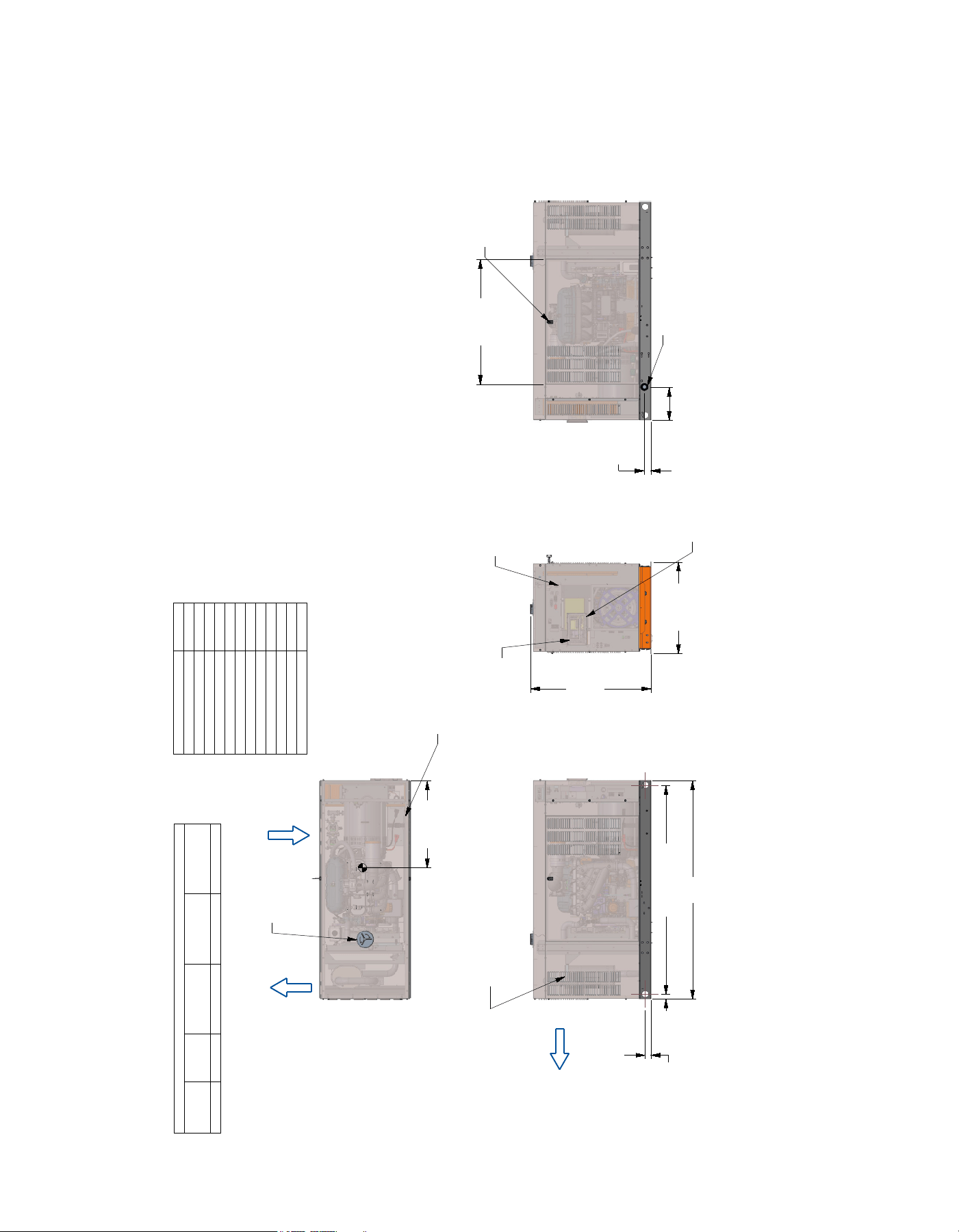
60 / 80 kW Installation Layout
Drawing A0000293264 Rev B (1 of 2)
4 3 2 1
4 3 1
A
B
A
B
1041.4 [41.00]
DOOR WIDTH TYP
960
[37.8]
CG (SEE NOTE 5)
2481 [97.7]
OVERALL LENGTH
109
[4.3]
1241 [48.9]
OVERALL
HEIGHT
63.5 [2.5]
LIFTING EYE
(4X)
47 TYP
[1.8]
2357 [92.8] TYP
964 [38.0]
OVERALL WIDTH
68 TYP
[2.7]
350
[13.8]
SERVICE ITEM 4.5L
OIL FILL CAP LEFT SIDE
OIL DIP STICK LEFT SIDE
OIL FILTER LEFT SIDE
OIL DRAIN HOSE LEFT SIDE
RADIATOR DRAIN HOSE RIGHT SIDE
COOLANT RECOVERY BOTTLE RIGHT SIDE
RADIATOR FILL CAP ROOF TOP
AIR CLEANER ELEMENT EITHER SIDE
SPARK PLUGS LEFT SIDE
MUFFLER SEE NOTE 11
FAN BELT EITHER SIDE
BATTERY LEFT SIDE
WEIGHT DATA
ENGINE/KW
ENCLOSURE
MATERIAL
WEIGHT
GENSET ONLY
KG [LBS]
WEIGHT
SHIPPING SKID
KG [LBS]
SHIPPING WEIGHT
KG [LBS]
4.5L/60KW AL 857 (1890) 79 [175] 936 (2064)
4.5L/80KW AL 903 (1990) 79 [175] 983 (2165]
TITLE
INSTALL G4.5L G26 60-80KW C3
ISSUE DATE:
SIZE CAGE NO DWG NO
A0000293264
REV
B
N/A
B
SCALE
0.035
WT-KG SHEET
1 of 2
GENERAC POWER SYSTEMS OWNS THE COPYRIGHT OF THIS DRAWING
WHICH IS SUPPLIED IN CONFIDENCE AND MUST NOT BE USED FOR
ANY PURPOSE OTHER THAN FOR WHICH IT IS SUPPLIED WITHOUT
THE EXPRESS WRITTEN CONSENT OF GENERAC POWER SYSTEMS.
c GENERAC POWER SYSTEMS 2013
ELECTRONICALLY APPROVED
INSIDE WINDCHILL
DRAWING CREATED FROM PRO/ENGINEER
3D FILE. ECO MODIFICATION TO BE
APPLIED TO SOLID MODEL ONLY.
SH
1/2
REV
B
WINDCHILL VERSION
B.3
NOTES:
1. MINIMUM RECOMMENDED CONCRETE PAD SIZE: (6" LARGER PER SIDE THAN GENERATOR)
1269 (50") WIDE 2786 (110") LONG.
REFERENCE INSTALLATION GUIDE SUPPLIED WITH UNIT FOR CONCRETE PAD GUIDELINES.
2. ALLOW SUFFICIENT ROOM ON ALL SIDES OF THE GENERATOR FOR MAINTENANCE
AND SERVICING. THIS UNIT MUST BE INSTALLED IN ACCORDANCE WITH CURRENT
APPLICABLE NFPA 37 AND NFPA 70 STANDARDS AS WELL AS ANY OTHER FEDERAL,
STATE, AND LOCAL CODES.
3. CONTROL PANEL / CIRCUIT BREAKER INFORMATION:
- SEE SPECIFICATION SHEET OR OWNERS MANUAL
- ACCESSIBLE THROUGH CUSTOMER ACCESS ASSEMBLY ON REAR OF GENERATOR.
4. INSIDE STUB-UP AREA FOR AC LOAD LEAD CONDUIT CONNECTION, NEUTRAL CONNECTION,
BATTERY CHARGER 120 VOLT AC (.5 AMP MAX) CONNECTION AND ACCESS TO TRANSFER
SWITCH CONTROL WIRES. REMOVE REAR COVER FOR ACCESS.
5. CENTER OF GRAVITY AND WEIGHT MAY CHANGE DUE TO UNIT OPTIONS.
6. BOTTOM OF GENERATOR SET MUST BE ENCLOSED TO PREVENT PEST INTRUSION AND
RECIRCULATION OF DISCHARGE AIR AND/OR IMPROPER COOLING AIR FLOW.
7. REFERENCE OWNERS MANUAL FOR LIFTING WARNINGS.
8. MOUNTING BOLTS OR STUDS TO MOUNTING SURFACE SHALL BE 5/8-11 GRADE 5
(USE STANDARD SAE TORQUE SPECS)
9. MUST ALLOW FREE FLOW OF INTAKE AIR, DISCHARGE AIR AND EXHAUST. SEE SPEC
SHEET FOR MINIMUM AIR FLOW AND MAXIMUM RESTRICTION REQUIREMENTS.
10. GENERATOR MUST BE INSTALLED SUCH THAT FRESH COOLING AIR IS AVAILABLE
AND THAT DISCHARGE AIR FROM RADIATOR IS NOT RECIRCULATED.
11. REMOVE FRONT END PANEL TO ACCESS EXHAUST MUFFLER. ACCESS AVAILABLE
THROUGH DOORS TO FAN BELT.
EXHAUST MUFFLER
ENCLOSED WITHIN
GENERATOR ENCLOSURE
SEE NOTES 9, 10 & 11
DIMENSIONS: MM [INCH]
RADIATOR/EXHAUST
DISCHARGE AIR
RADIATOR/EXHAUST
DISCHARGE AIR
(BOTH SIDES)
AIR INTAKE
(BOTH SIDES)
LEFT VIEW
CIRCUIT BREAKER
SEE NOTE 3
REFERENCE OWNERS MANUAL
FOR PERIODIC REPLACEMENT
PART LISTINGS.
REAR ENCLOSURE
COVER PANEL
SEE NOTE 4
CUSTOMER ACCESS
ASSEMBLY, CONTROL
PANEL ACCESS
BATTERY CHARGER
LOCATED WITHIN
SEE NOTE 3 & 4
REAR VIEW
VICE ACTION LATCH
ONE PER DOOR
ONE LIFT OFF DOOR PER
SIDE OF GENERATOR
RIGHT VIEW
FUEL LINE CONNECTION
1-1/4" NPT FEMALE TEE
THROUGH BASE FRAME OPENING
RADIATOR DRAIN
TOP VIEW
BATTERY 12V
GRP 27F
NEGATIVE GROUND
P/N G058665
REMOVE COVER FOR
ACCESS TO RADIATOR
FILL CAP
OIL DRAIN
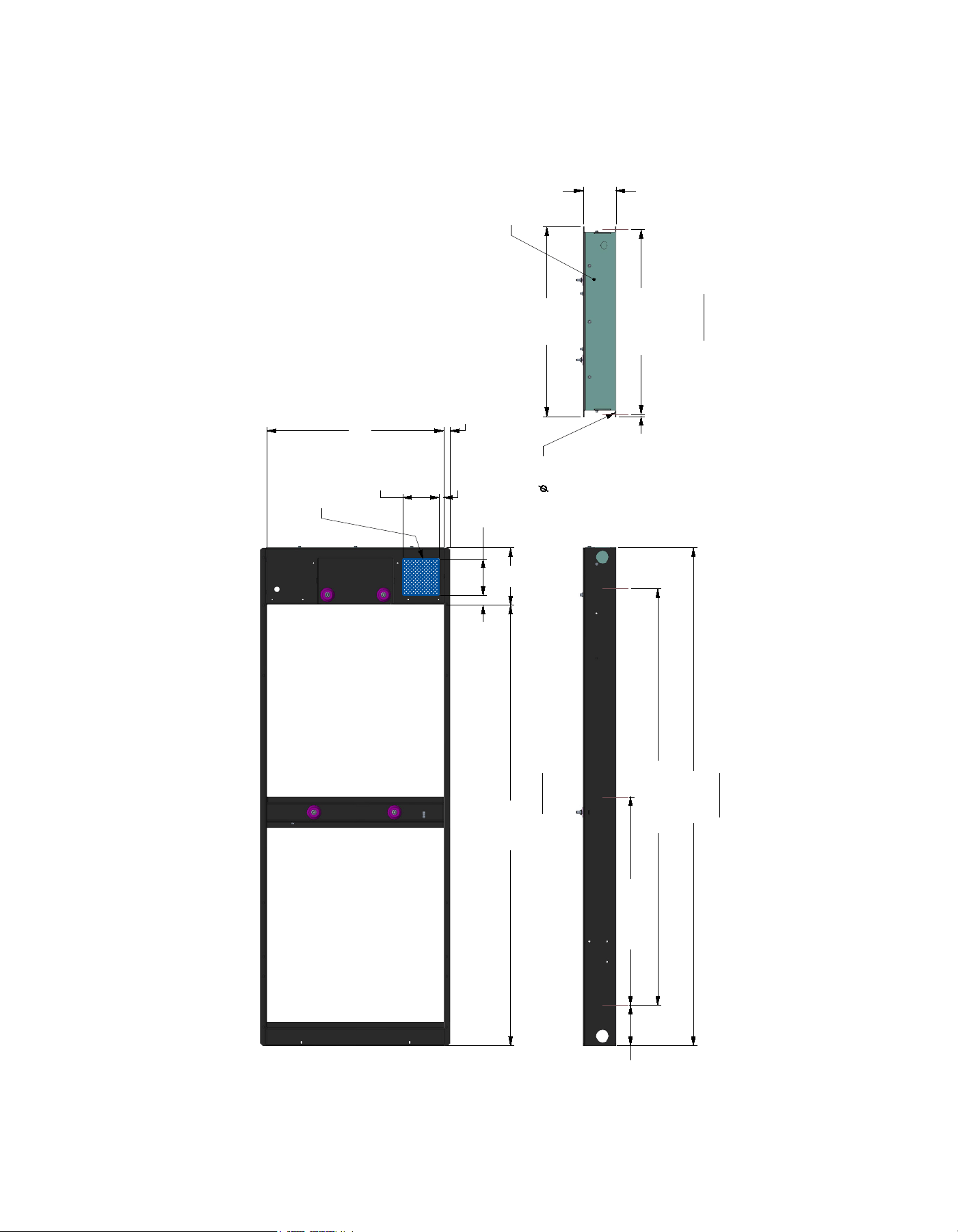
60 / 80 kW Installation Layout
Drawing A0000293264 Rev B (2 of 2)
4 3 2 1
4 3 1
A
B
A
B
935 [36.8]
TYP
2170 [85.4]
47 [1.9]
282
[11.1]
180 [7.1]
*STUB-UP
AREA
180 [7.1]
*STUB-UP
AREA
909 [35.8] TYP
MOUNTING CENTERS
200 [7.9] TYP
MOUNTING CENTERS
2050 [80.7] TYP
MOUNTING CENTERS
161 [6.3]
13 [.5]
TYP
22
[.87]
871
[34.3]
32
[1.3]
2452 [96.5]
1025 [40.4] TYP
MOUNTING CENTERS
DRAWING CREATED FROM PRO/ENGINEER
3D FILE. ECO MODIFICATION TO BE
APPLIED TO SOLID MODEL ONLY.
TITLE
INSTALL STUB-UP VIEW
G4.5L G26 60-80KW C3
ISSUE DATE:
SIZE CAGE NO DWG NO
A0000293264
REV
B
N/A
B
SCALE
0.080
WT-KG SHEET
2 of 2
GENERAC POWER SYSTEMS OWNS THE COPYRIGHT OF THIS DRAWING
WHICH IS SUPPLIED IN CONFIDENCE AND MUST NOT BE USED FOR
ANY PURPOSE OTHER THAN FOR WHICH IT IS SUPPLIED WITHOUT
THE EXPRESS WRITTEN CONSENT OF GENERAC POWER SYSTEMS.
c GENERAC POWER SYSTEMS 2013
ELECTRONICALLY APPROVED
INSIDE WINDCHILL
SH
2/2
REV
B
WINDCHILL VERSION
B.3
*NOTE:
STUB-UP AREA FOR HIGH AND LOW
VOLTAGE CONNECTIONS, CIRCUIT BREAKER,
NEUTRAL AND CUSTOMER CONNECTION OPENING.
LEFT VIEW
TOP VIEW
HIGH AND LOW
VOLTAGE
STUB-UP AREA
REAR VIEW
REMOVABLE
STUB-UP COVER
13.5 [.5]
MOUNTING HOLES
(6X)
MODEL # PRODUCT DESCRIPTION
G007992-0 Cold Weather Kit
If the temperature regularly falls below 32 °F (0 °C), install a cold weather kit to maintain optimal battery
temperature. The cold weather kit consists of a battery warmer with thermostat built into the wrap.
G007990-0 Extreme Cold Weather Kit
Recommended where the temperature regularly falls below 32 °F (0 °C) for extended periods of time.
For liquid cooled units only.
G005651-0 Base Plug Kit Add base plugs to the base of the generator to keep out debris.
G006160-0 Touch-Up Paint Kit
If the generator enclosure is scratched or damaged, it is important to touch-up the paint to protect from
future corrosion. The touch-up paint kit includes the necessary paint to correctly maintain or touch-up a
generator enclosure.
G007991-0 Scheduled Maintenance Kit
The liquid-cooled scheduled maintenance kit provides all the items necessary to perform complete routine
maintenance on Honeywell liquid-cooled generators (oil not included).
G006664-0 Local Wireless Remote Monitor
Completely wireless and battery powered, the wireless remote monitor provides the user with instant status
information without ever leaving the house.
G006665-0
Wireless Remote Monitor Extension
Harness
Recommended for use with the wireless remote monitor on units up to 60 kW, required for use on units 70
kW or greater.
G007993-0 E-Stop E-stop allows for immediate fuel shutoff and generator shutdown in the event of an emergency.
G007005-0 Wi-Fi LP Tank Fuel Level Monitor
The Wi-Fi enabled LP tank fuel level monitor provides constant monitoring of the connected LP fuel tank.
Monitoring the LP tank’s fuel level is an important step in verifying the generator is ready to run during an
unexpected power failure. Status alerts are available through a free application to notify users when the LP
tank is in need of a refill.
G007000-0 - 50 amps
G007006-0 - 100 amps
Smart Management Module
Smart Management Modules (SMM) are used to optimize the performance of a standby generator. They
manage large electrical loads upon startup and shed them to aid in recovery when overloaded. In many
cases, using SMM's can reduce the overall size and cost of the system.
G007169-0
Mobile Link® 4G LTE Cellular Accessory
The Mobile Link 4G LTE Cellular Accessory
allow users to monitor generator status from anywhere in the
world using a smart phone, tablet, or PC. Easily access information such as the current operating status and
maintenance alerts. Users can connect an account with an authorized service dealer for fast, friendly, and
proactive service. With Mobile Link, users are taken care of before the next power outage,
G006478-0 Harness Adapter Kit
The harness adapter kit is required to make liquid-cooled units compatible with Mobile Link® 4G LTE
Cellular Accessory.
48 / 60 / 80 kW Available Accessories
©2021 Generac Power Systems, Inc. All rights reserved.
Specifications subject to change without notice.
The Honeywell trademark is used under license from Honeywell
International Inc.
Honeywell International Inc. makes no representation or warranties
with respect to this product. This product is manufactured by
Generac Power Systems, Inc., Waukesha, WI. 53189, USA.
A0000379120 | Rev C | 04/2021
Generac Power Systems, Inc.
S45 W29290 Hwy 59
Waukesha, WI. 53189
1.855.GEN.INFO
www.honeywellgenerators.com