
Loading ...
Loading ...
Loading ...
13
FIGURE 11
ADJUSTMENTS
ADJUST THE SPINDLE TILT
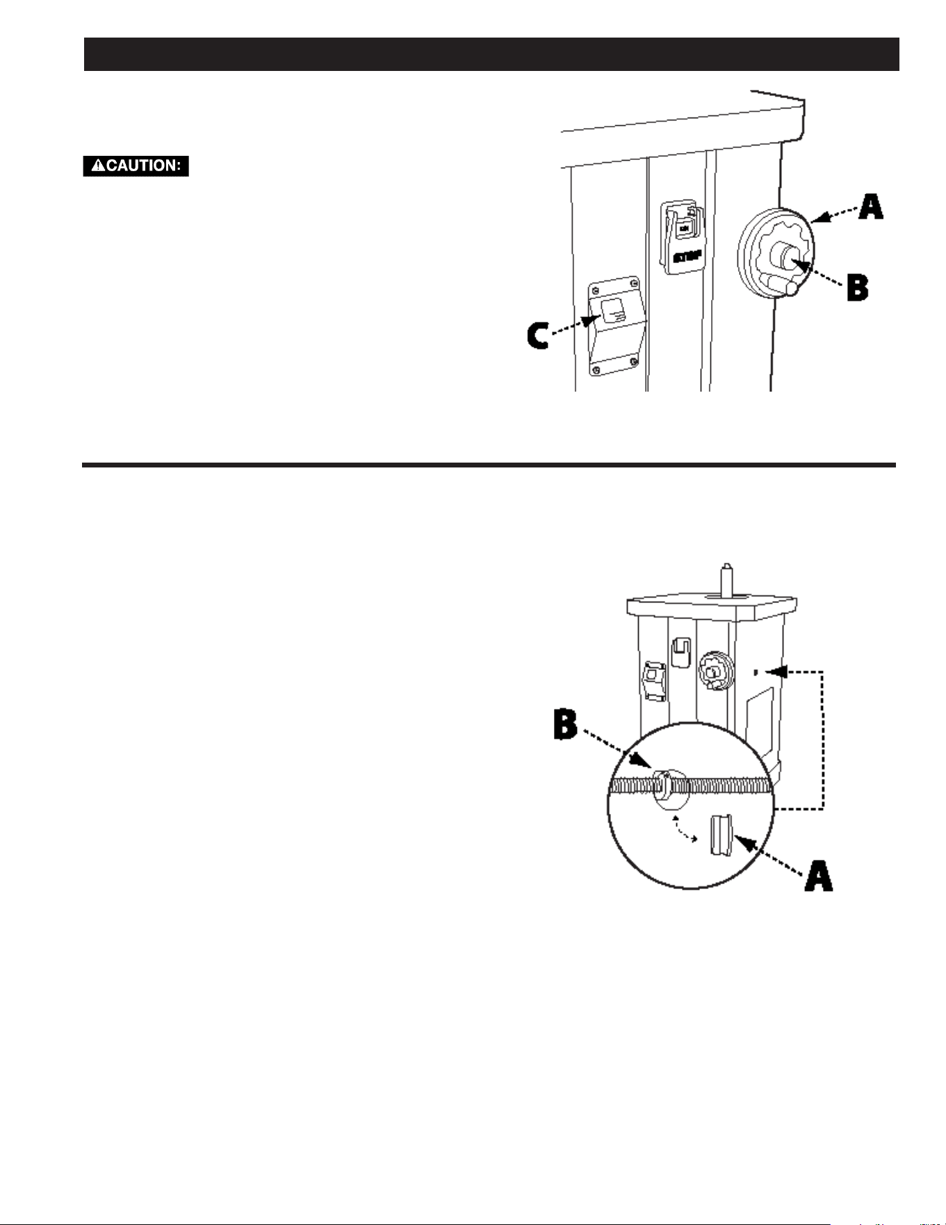
See Figure 11
For any bevel sanding operation, you
must use a table insert with an oblong-
shaped opening. Failure to do so may lead to serious
injury and / or damage to machine or the work piece.
1. Loosen the spindle tilt lock knob (A).
2. Rotate the spindle tilt wheel (B), using the tilt
indicator (C) for reference.
3. Once the spindle is at the desired angle, re-tighten
the spindle tilt lock knob.
ADJUST THE 90° AND 45° POSITIVE STOPS
See Figure 6
To adjust the 90° positive stop, see the section
“SQUARE THE TABLE TO THE SPINDLE” on page 11.
To adjust the 45° positive stop, refer to Figure 12
and do the following:
NOTE: The 90° stop must be adjusted and squared to
table BEFORE the 45° stop can be adjusted.
1. Verify the spindle is square to the table surface and
the tilt indicator is set to 90°.
2. Unlock the spindle tilt lock knob and rotate the
spindle tilt wheel until the tilt indicator reaches 45°.
3. Locate and remove the rubber access plug (A) on
the right side of the machine.
4. Using a 3 mm Allen wrench, loosen the 2 set screws
on the 45° positive stop collar (B).
5. Hold the collar in place with the wrench and rotate
the spindle tilt wheel. This will reposition the 45°
positive stop collar on the threaded rod.
6. Using a measuring triangle, check the angle of the
spindle to the table, repeating step 4 above until the
spindle is at a 45° angle to the table.
7. Tighten the 45° positive stop collar set screw and
replace the access plug.
8. Lock the spindle tilt lock knob.
FIGURE 12
Loading ...
Loading ...
Loading ...