
Explosion-Proof Thermal Bi-Spectrum
Network Positioning System
Quick Start Guide

Thermal Network Positioning System·Quick Start Guide
ii
Legal Information
© 2022 Hangzhou Hikvision Digital Technology Co., Ltd. All rights reserved.
About this Manual
The Manual includes instructions for using and managing the Product. Pictures, charts,
images and all other information hereinafter are for description and explanation only.
The information contained in the Manual is subject to change, without notice, due to
firmware updates or other reasons. Please find the latest version of this Manual at the
Hikvision website (https://www.hikvision.com).
Please use this Manual with the guidance and assistance of professionals trained in
supporting the Product.
Trademarks Acknowledgement
and other Hikvision's trademarks and logos are the properties of
Hikvision in various jurisdictions.
Other trademarks and logos mentioned are the properties of their respective owners.
Disclaimer
TO THE MAXIMUM EXTENT PERMITTED BY APPLICABLE LAW, THIS MANUAL AND THE
PRODUCT DESCRIBED, WITH ITS HARDWARE, SOFTWARE AND FIRMWARE, ARE
PROVIDED “AS IS” AND “WITH ALL FAULTS AND ERRORS”. HIKVISION MAKES NO
WARRANTIES, EXPRESS OR IMPLIED, INCLUDING WITHOUT LIMITATION,
MERCHANTABILITY, SATISFACTORY QUALITY, OR FITNESS FOR A PARTICULAR PURPOSE.
THE USE OF THE PRODUCT BY YOU IS AT YOUR OWN RISK. IN NO EVENT WILL HIKVISION
BE LIABLE TO YOU FOR ANY SPECIAL, CONSEQUENTIAL, INCIDENTAL, OR INDIRECT
DAMAGES, INCLUDING, AMONG OTHERS, DAMAGES FOR LOSS OF BUSINESS PROFITS,
BUSINESS INTERRUPTION, OR LOSS OF DATA, CORRUPTION OF SYSTEMS, OR LOSS OF
DOCUMENTATION, WHETHER BASED ON BREACH OF CONTRACT, TORT (INCLUDING
NEGLIGENCE), PRODUCT LIABILITY, OR OTHERWISE, IN CONNECTION WITH THE USE OF
THE PRODUCT, EVEN IF HIKVISION HAS BEEN ADVISED OF THE POSSIBILITY OF SUCH
DAMAGES OR LOSS.
YOU ACKNOWLEDGE THAT THE NATURE OF THE INTERNET PROVIDES FOR INHERENT
SECURITY RISKS, AND HIKVISION SHALL NOT TAKE ANY RESPONSIBILITIES FOR
ABNORMAL OPERATION, PRIVACY LEAKAGE OR OTHER DAMAGES RESULTING FROM
CYBER-ATTACK, HACKER ATTACK, VIRUS INFECTION, OR OTHER INTERNET SECURITY
RISKS; HOWEVER, HIKVISION WILL PROVIDE TIMELY TECHNICAL SUPPORT IF REQUIRED.
YOU AGREE TO USE THIS PRODUCT IN COMPLIANCE WITH ALL APPLICABLE LAWS, AND
YOU ARE SOLELY RESPONSIBLE FOR ENSURING THAT YOUR USE CONFORMS TO THE
APPLICABLE LAW. ESPECIALLY, YOU ARE RESPONSIBLE, FOR USING THIS PRODUCT IN A
Thermal Network Positioning System·Quick Start Guide
iii
MANNER THAT DOES NOT INFRINGE ON THE RIGHTS OF THIRD PARTIES, INCLUDING
WITHOUT LIMITATION, RIGHTS OF PUBLICITY, INTELLECTUAL PROPERTY RIGHTS, OR
DATA PROTECTION AND OTHER PRIVACY RIGHTS. YOU SHALL NOT USE THIS PRODUCT
FOR ANY PROHIBITED END-USES, INCLUDING THE DEVELOPMENT OR PRODUCTION OF
WEAPONS OF MASS DESTRUCTION, THE DEVELOPMENT OR PRODUCTION OF CHEMICAL
OR BIOLOGICAL WEAPONS, ANY ACTIVITIES IN THE CONTEXT RELATED TO ANY NUCLEAR
EXPLOSIVE OR UNSAFE NUCLEAR FUEL-CYCLE, OR IN SUPPORT OF HUMAN RIGHTS
ABUSES.
IN THE EVENT OF ANY CONFLICTS BETWEEN THIS MANUAL AND THE APPLICABLE LAW,
THE LATTER PREVAILS.
Regulatory Information
FCC Information
FCC compliance: This equipment has been tested and found to comply with the limits
for a Class A digital device, pursuant to part 15 of the FCC Rules. These limits are
designed to provide reasonable protection against harmful interference when the
equipment is operated in a commercial environment. This equipment generates, uses,
and can radiate radio frequency energy and, if not installed and used in accordance with
the instruction manual, may cause harmful interference to radio communications.
Operation of this equipment in a residential area is likely to cause harmful interference
in which case the user will be required to correct the interference at his own expense.
FCC Conditions
This device complies with part 15 of the FCC Rules. Operation is subject to the following
two conditions:
1. This device may not cause harmful interference.
2. This device must accept any interference received, including interference that may
cause undesired operation
EU Conformity Statement
This product and - if applicable - the supplied accessories too are marked
with "CE" and comply therefore with the applicable harmonized European
standards listed under the EMC Directive 2014/30/EU, the RoHS Directive
2011/65/EU, the ATEX Directive 2014/34/EU.
2012/19/EU (WEEE directive): Products marked with this symbol cannot be
disposed of as unsorted municipal waste in the European Union. For proper
recycling, return this product to your local supplier upon the purchase of
equivalent new equipment, or dispose of it at designated collection points.
For more information see: www.recyclethis.info.
2006/66/EC (battery directive): This product contains a battery that cannot
be disposed of as unsorted municipal waste in the European Union. See the
product documentation for specific battery information. The battery is
marked with this symbol, which may include lettering to indicate cadmium
(Cd), lead (Pb), or mercury (Hg). For proper recycling, return the battery to
Thermal Network Positioning System·Quick Start Guide
iv
your supplier or to a designated collection point. For more information see:
www.recyclethis.info.
Intended use of the camera
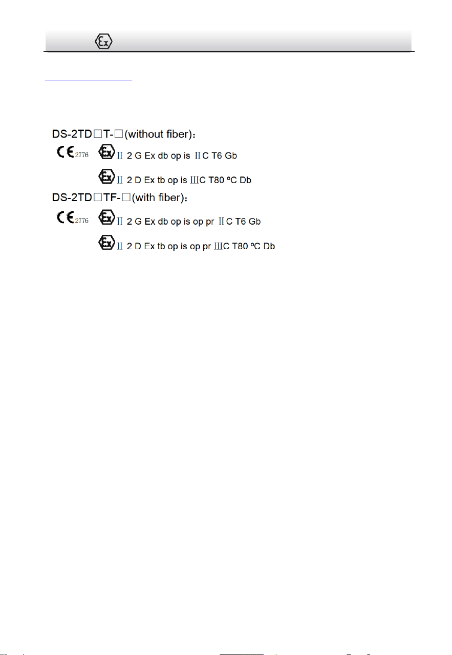
Ex mark:
Hazardous Area Classification: Zone 1, Zone 2, Zone 21, Zone 22.
IP Degree: IP68 (2m, 2h)
Ex Standards:
IEC 60079-0: 2017
EN IEC 60079-0: 2018
IEC 60079-1: 2014
EN 60079-1: 2014
IEC 60079-28: 2015
EN IEC 60079-0: 2018
IEC 60079-31: 2013
EN 60079-31: 2014
Special Conditions for Safe Use:
1. Ambient Temperature: -40°C to 60°C.
2. The width of flameproof joint is more than the minimum values specified in
IEC60079-1 standard. If needed, repair of the flameproof joints must only be made in
compliance with the structural specifications provided by the manufacturer. Repairs
must not be made on the basis of values specified in table 4 of IEC60079-1:2014.
3. When installation, the free end of the composite cable should be taken into the inside
of the end-equipment enclosure that is Ex apparatus, or safety area.
4. For type DS-2TD6566TF-*/** Explosion-proof thermal bi-spectrum network
positioning system, When installation, the free end of the composite cable with fiber
should be taken into the inside of the end-equipment enclosure that is Ex apparatus,
or the electrical Ex components (e.g. fiber optic terminal devices), or safety area.
5. DO NOT OPEN WHEN ENERGIZED.
6. USE FASTENERS WITH YIELD STRESS ≥ 450 MPa.
Industry Canada ICES-003 Compliance

Thermal Network Positioning System·Quick Start Guide
v
This device meets the CAN ICES-3 (A)/NMB-3(A) standards requirements.
Safety Instruction
These instructions are intended to ensure that user can use the product correctly to
avoid danger or property loss.
The precaution measure is divided into Warnings and Cautions:
Warnings: Neglecting any of the warnings may cause serious injury or death.
Cautions: Neglecting any of the cautions may cause injury or equipment damage.
Warnings
Grounding:
The both internal and external earthing shall be connected reliably.
Ground wire cross-sectional area of not less than the phase connector cross-sectional
area level, at least 4 mm².
The device should be used in compliance with local laws and electrical safety
regulations. Refer to the appropriate documentation for detailed information.
The input voltage should conform to IEC60950-1 standard: SELV (Safety Extra Low
Voltage) and the Limited Power Source (85 to 265 VAC). Refer to the appropriate
documentation for detailed information.
DO NOT connect multiple devices to one power adapter, to avoid over-heating or fire
hazards caused by overload.
Make sure the plug is properly connected to the power socket.
If smoke, odor, or noise arises from the device, immediately turn off the power,
unplug the power cable, and contact the service center.
The installer and user are responsible for password and security configuration and its
settings.
Both internal and external grounds should be connected properly. (The cross section
area of the grounding wire must be no less than 4 mm², and no less than that of the
phase connector).
For permanently connected equipment the disconnect device shall be incorporated in
the equipment, unless the equipment is accompanied by installation instructions
stating that an appropriate disconnect device shall be provided as part of the building
installation.
Warnings Follow
these safeguards to
prevent serious
injury or death.
Cautions Follow these
precautions to prevent
potential injury or
material damage.

Thermal Network Positioning System·Quick Start Guide
vi
Cautions
To ensure explosion-proof performance, do not damage explosion-proof surface
Do not drop the device or subject it to physical shock.
Wipe the device gently with a clean cloth and a small quantity of ethanol, if
necessary.
Do not aim the lens at the sun or any other bright light.
When any laser equipment is in use, make sure that the device lens is not exposed to
the laser beam, or it may burn out.
Do not expose the device to high electromagnetic radiation or extremely hot, cold,
dusty, or damp environments.
Place the device in a dry and well-ventilated environment.
Keep non-waterproof devices away from liquids.
Keep the device in original or similar packaging while transporting it.
A few device components (e.g., electrolytic capacitor) require regular replacement.
The average lifespan varies, so periodic checking is recommended. Contact your
dealer for details.
Improper use or replacement of the battery may result in explosion hazard. Replace
with the same or equivalent type only. Dispose of used batteries in conformance with
the instructions provided by the battery manufacturer.
Never attempt to disassemble the device.
Ex structure instruction
We have made adequate consideration in flameproof enclosure design of the
explosion-proof camera to prevent explosive gases getting into the inner volume, the
explosion inside the enclosure cannot cause the explosion of the external explosive
gases. We ensure the explosion-proof performance by strengthen enclosure the
strength, adjust the length and gap of the joint of associate components and limit the
maximum surface temperature.
The enclosure is able to subject to static pressure test (1.5 times of reference pressure
for at least 10s) specified in EN60079-01/IEC60079-1, no leakage or deformation
allowed after test.
The maximum surface temperature will no more than 80ºC in normal operation.
Tempering glass is adopted in observation port, the tempering glass shall pass the
impact and thermal shock test.
Protection the flameproof surface in maintaining of this product, otherwise the
damaged flameproof surface will affect the Explosion-proof performance.
Thermal Network Positioning System·Quick Start Guide
vii

Thermal Network Positioning System·Quick Start Guide
viii
Table of Contents
1 Introduction ................................................................................................. 1
1.1 Overview .................................................................................................................. 1
1.2 Model Description ................................................................................................... 1
2 Preparation .................................................................................................. 4
3 Appearance Description ............................................................................... 5
3.1 Positioning System Appearance ............................................................................... 5
3.2 Cable Descriptions ................................................................................................... 5
3.3 Alarm In/Out Connections ....................................................................................... 6
4 Installing the Positioning System .................................................................. 8
4.1 Monitoring Distance Range ..................................................................................... 8
4.2 Wiring ...................................................................................................................... 8
4.3 Bracket Installation .................................................................................................. 9
4.4 Explosion-proof Tube Installaion (without fiber) ................................................... 11
4.5 Explosion-proof control box(ATEX/IECEx certificates ) Installation (without fiber) 12
4.6 Explosion-proof control box(ATEX/IECEx certificates ) Installation (with fiber) ..... 14
4.7 Finishing Installing ................................................................................................. 15
5 Setting the System over the LAN ................................................................ 16
5.1 Wiring .................................................................................................................... 16
5.2 Activating the System ............................................................................................ 16
5.2.1 Activation via Web Browser ............................................................................ 16
5.2.2 Activation via SADP Software ...........................................................................17
5.3 Modifying the IP Address ....................................................................................... 18
6 Operating via Web browser ........................................................................ 20
6.1 Accessing the System ............................................................................................. 20
6.2 Live View Page ....................................................................................................... 21
Appendix ...................................................................................................... 23
Frequently Asked Questions (FAQ) .............................................................................. 23
Device Running Error ............................................................................................... 23
Device Upgrading ..................................................................................................... 23
Others ...................................................................................................................... 23
Common Material Emissivity Reference ...................................................................... 25

Thermal Network Positioning System·Quick Start Guide
1
1 Introduction
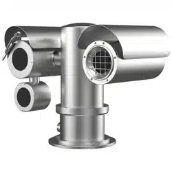
1.1 Overview
Explosion-Proof Thermal Bi-spectrum Network Positioning System is a surveillance
product capable of video/audio collecting, smart encoding and network transmitting. It
adopts an embedded system and a high-performed hardware process platform to
achieve good stability and reliability.
You can visit and configure your camera via web browser and client software.
Explosion-Proof Thermal Bi-spectrum Network Positioning System adopts a stainless
steel enclosure, receiving an IP68 rating for ingress protection.
The camera is designed and manufactured according to EN IEC60079-0:2018, EN60079-1:
2014, EN60079-28: 2015, EN60079-31: 2014, IEC60079-0: 2017, IEC60079-1: 2014,
IEC60079-28: 2015, IEC60079-31: 2013.All associate technical document, drawings and
samples of the camera are tested and certified by China National Quality Supervision
and Test Center for Explosion Protected Electrical Apparatus (CQST), ATEX certification
number: CNEX 19 ATEX 0040X and IECEx certification number is IECEx CNEX
19.0030X.
Application Scenarios: oil industry, mine fields, chemical industry, port, grain processing
industry, etc.
1.2 Model Description

Thermal Network Positioning System·Quick Start Guide
2
Explanation of model naming:
Lens focal length (mm):
25: 25 mm; 50: 50 mm
DS-2
T D 6 5 X X/XT
Hikvision front-end product
For specialized application
Thermal camera
Shape:
6: Positioning System
Max. Resolution (MP): 6: 0.3 MP
Stands for Thermal camera module component performance
T: Accurate temperature measurement
- X X
Explosion-proof camera
X
X X /X
IR Light
Optical Max. Resolution (MP):
2: 2 MP; 5:5MP
Optical camera module component type
Software Platform
Figure 1-1 Model Explanation
Models:
DS-2TD6566T-25H2LX/V2, DS-2TD6566T-50H2LX/V2,
DS-2TD6566T-25H2LX/V2UHK, DS-2TD6566T-25H2LX/V2CKV,
DS-2TD6566T-25H2LX/V2UVS, DS-2TD6566T-25H2LX/V2KVO,
DS-2TD6566T-25H2LX/V2HUN, DS-2TD6566T-50H2LX/V2UHK,
DS-2TD6566T-50H2LX/V2CKV, DS-2TD6566T-50H2LX/V2UVS,
DS-2TD6566T-50H2LX/V2KVO, DS-2TD6566T-50H2LX/V2HUN (Main cylinder normal
without fiber)
DS-2TD6566T-25H2LX/W, DS-2TD6566T-50H2LX/W,
DS-2TD6566T-25H2LX/WUHK, DS-2TD6566T-25H2LX/WCKV,
DS-2TD6566T-25H2LX/WUVS, DS-2TD6566T-25H2LX/WKVO,
DS-2TD6566T-25H2LX/WHUN, DS-2TD6566T-50H2LX/WUHK,
DS-2TD6566T-50H2LX/WCKV, DS-2TD6566T-50H2LX/WUVS,

Thermal Network Positioning System·Quick Start Guide
3
DS-2TD6566T-50H2LX/WKVO, DS-2TD6566T-50H2LX/WHUN (Main cylinder heighten
without fiber)
DS-2TD6566TF-25H2LX/V2, DS-2TD6566TF-50H2LX/V2,
DS-2TD6566TF-25H2LX/V2UHK, DS-2TD6566TF-25H2LX/V2CKV
DS-2TD6566TF-25H2LX/V2UVS, DS-2TD6566TF-25H2LX/V2KVO
DS-2TD6566TF-25H2LX/V2HUN, DS-2TD6566TF-50H2LX/V2UHK
DS-2TD6566TF-50H2LX/V2CKV, DS-2TD6566TF-50H2LX/V2UVS
DS-2TD6566TF-50H2LX/V2KVO, DS-2TD6566TF-50H2LX/V2HUN (Main cylinder normal
with fiber)
DS-2TD6566TF-25H2LX/W, DS-2TD6566TF-50H2LX/W,
DS-2TD6566TF-25H2LX/WUHK, DS-2TD6566TF-25H2LX/WCKV,
DS-2TD6566TF-25H2LX/WUVS, DS-2TD6566TF-25H2LX/WKVO,
DS-2TD6566TF-25H2LX/WHUN, DS-2TD6566TF-50H2LX/WUHK,
DS-2TD6566TF-50H2LX/WCKV, DS-2TD6566TF-50H2LX/WUVS,
DS-2TD6566TF-50H2LX/WKVO, DS-2TD6566TF-50H2LX/WHUN (Main cylinder heighten
with fiber)
DS-2TD6536T-9H2LX/V2, DS-2TD6566T-9H2LX/ V2, DS-2TD6536T-15H2LX/ V2,
DS-2TD6566T-15H2LX/ V2, DS-2TD6536T-25H2LX/ V2, DS-2TD6566T-25H2LX/ V2,
DS-2TD6536T-50H2LX/ V2, DS-2TD6566T-50H2LX/ V2, DS-2TD6536T-75H2LX/ V2,
DS-2TD6566T-75H2LX/ V2, DS-2TD6536T-AH2LX/ V2, DS-2TD6566T-AH2LX/ V2,
DS-2TD6536T-BH2LX/ V2, DS-2TD6566T-BH2LX/ V2, DS-2TD6536T-CH2LX/ V2,
DS-2TD6566T-CH2LX/ V2, DS-2TD6536T-DH2LX/ V2, DS-2TD6566T-DH2LX/ V2,
DS-2TD6537T-9H4LX/W, DS-2TD6567T-9H4LX/W, DS-2TD6537T-15H4LX/W,
DS-2TD6567T-15H4LX/W, DS-2TD6537T-25H4LX/W, DS-2TD6567T-25H4LX/W,
DS-2TD6537T-50H4LX/W, DS-2TD6567T-50H4LX/W, DS-2TD6537T-75H4LX/W,
DS-2TD6567T-75H4LX/W, DS-2TD6537T-AH4LX/W, DS-2TD6567T-AH4LX/W,
DS-2TD6537T-BH4LX/W, DS-2TD6567T-BH4LX/W, DS-2TD6537T-CH4LX/W,
DS-2TD6567T-CH4LX/W, DS-2TD6537T-DH4LX/W, DS-2TD6567T-DH4LX/W,
DS-2TD65AD-Q, DS-2TD65AD-W, DS-2TD65AD-E, DS-2TD65AD-R

Thermal Network Positioning System·Quick Start Guide
4
2 Preparation
Basic Requirement
All the electronic operation should be strictly compliance with the electrical safety
regulations, fire prevention regulations and other related regulations in your local
region.
Check the package contents and make sure that the device in the package is in
good condition and all the assembly parts are included.
Use the system according to the working environment requirement.
Checking Installing Environment
Be sure that there is enough space to install the positioning system and
accessories.
Make sure that the wall is strong enough to withstand at least 8 times the weight
of the system and the mount.
Preparing Cables
According to the actual network bandwidth, the Cat5 (in 100M) or Cat6 (100M
above) is needed.
When the Positioning System uses standard 24 VAC power supply, the power cable
should be American wire gauge 18 or above. The formula of the cross-section S
(mm²) and the maximum transmission distance L (m) of the bare wire is L=50*S.
Choose the video cable according to the transmission length. The video should
meet the least demands as: 75Ω resistance; 100% copper core conducting wire;
95% weaving copper shield.
Preparing Tools
Before installation, please prepare the tools needed, such as the expansion screws,
electric hammer, electric drill, wrench, screwdriver, electroprobe and network
cable.
Original Packaging
When you unpack the positioning system, please keep the original package
properly, in case of returning or repairing the positioning system, you can pack the
positioning system with the package.
Note: The user should be responsible for any damage caused when transporting
with unoriginal package.

Thermal Network Positioning System·Quick Start Guide
5
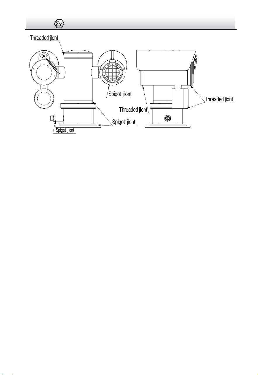
3 Appearance Description
3.1 Positioning System Appearance
Refer to the following figures for thermal positioning system overview.
Figure 3-1 Thermal Positioning System Overview
Table 3-1 Description of Thermal Positioning System
No.
Description
1
Optical
2
IR Light
3
Power Cable
4
Thermal
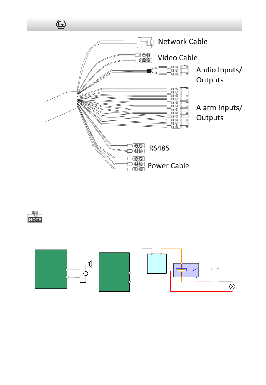
3.2 Cable Descriptions
The cable interfaces of positioning system are shown in Figure 3-2. The cables of power
supply, alarm inputs, alarm outputs, etc. are distinguished by different colors. Please
refer to the labels attached on the cables for identification.
Thermal Network Positioning System·Quick Start Guide
6
Figure 3-2 Cables of Positioning Systems
3.3 Alarm In/Out Connections
This section is only for the positioning system with alarm in/out functions.
The positioning system can be connected with alarm inputs (0~5VDC) and alarm outputs.
Refer to the following diagrams for alarm output:
JQC-
3FG
Relay
30VDC
GND OUT
L N
~
220V AC
Relay Output
(10A 250VAC)
Diagram (left)
Diagram (right)
1A
OUT(n)
OUT(n)
+
-
DC
DC Load
Relay Output
Positioning System
OUT(n)
OUT(n)
Positioning System
Figure 3-3 Alarm Out Connections
The alarm provides the relay output (no voltage), and the external power supply is
required when it connects to the alarm device.
For DC power supply (left diagram), the input voltage must be no more than 30VDC,
1A.

Thermal Network Positioning System·Quick Start Guide
7
For AC power supply, the external relay must be used (right diagram) to prevent
damages to the positioning system and avoid risk of electric shock.

Thermal Network Positioning System·Quick Start Guide
8
4 Installing the Positioning System
4.1 Monitoring Distance Range
Electric lens is adopted for the thermal channel of positioning system. It supports
auto-focus function and remote focus function. For different lens focal length, the
monitoring range is shown in the table below:
Table 4-1 Monitoring Range (Pixel Interval: 17um)
Lens Focal Length/mm
25
50
75
100
MRAD
0.68
0.34
0.23
0.17
Detection Range (Vehicle)/m
2255
4510
6765
9020
Detection Range (Human)/m
735
1471
2206
2941
Recognition Range
(Vehicle)/m
564
1127
1691
2255
Recognition Range
(Human)/m
184
368
551
735
Identification Range
(Vehicle)/m
282
564
846
1127
Identification Range
(Human)/m
92
184
276
368
This table is for reference only, and the actual detection range may vary according to
different camera settings, mounting condition, monitor and so on.
When the weather is fine and the atmospheric visibility is normal, the probability of
detecting/recognizing/identifying target is 50%.
The human width is presumed as 0.5m (human width cannot exceed 0.75m), the
human height is presumed as 1.8m, and the vehicle width cannot exceed 2.3m.
4.2 Wiring
Please fully take into consideration the installation environment and position of the
positioning system when you plan for the wiring. In order to make sure the stable power
supply and signal transmission, please closely follow the rules below:

Thermal Network Positioning System·Quick Start Guide
9
Please get familiar with the installation environment before you wiring, including the
wiring distance, wiring environment, keeping magnetic-field interference away, etc.
Please make sure the rated voltage of the cable is higher than that the device
requires, thus guarantee the device can work normally when the voltage instability
occurs.
Please avoid the interrupt line connection
It’s recommended to use a single complete cable for the device connection; if not,
reinforce and protective measures should be taken for the wiring point between two
cables, in case the circuit aging will make the device work abnormally.
Make sure the video cable and the signal transmission cable are well protected. And
pay attention to reinforce and protective measures during wiring.
Make sure the cables are not too redundant or being stretched too tight.
Under normal circumstances, the wiring is completed by the professional technicians.
However, when the device cannot work normally, you can check the above
information to look for reason.
4.3 Bracket Installation
Steps:
2. Drill four φ16.5 holes in the wall according to the screw hole sites of the racket.
140mm (5.51")
150mm(5.91")
Figure 1-2 Dimension of a Wall Mounting Bracket
3. Insert four M12 expansion screws into the screw holes.

Thermal Network Positioning System·Quick Start Guide
10
Figure 1-3 Drill Expansion Screws
4. Align the holes on the bracket with the position of expansion screws, Install the
bracket plate onto the wall, and tighten the expansion screws.
Figure 1-4 Install Bracket Plate
5. Align the holes on the camera with the holes of bracket, fix the camera with M10
screws.
Figure 1-5 Install Camera

Thermal Network Positioning System·Quick Start Guide
11
4.4 Explosion-proof Tube Installaion (without fiber)
Purpose
:
You must use the explosion-proof tube and junction box to prevent the explosive gas
from entering into the camera through the cable. Or it may cause danger.
Steps:
1. Cut all terminals of the cable.
Figure 1-6 Cut all terminals
2. Unscrew one cable gland of the explosion-proof tube, route the cable through the
tube.
3. Screw the explosion-proof tube with the thread connector of camera.
Unscrew the
Cable Gland
Screw
Figure 1-7 Explosion-proof Tube
Thermal Network Positioning System·Quick Start Guide
12
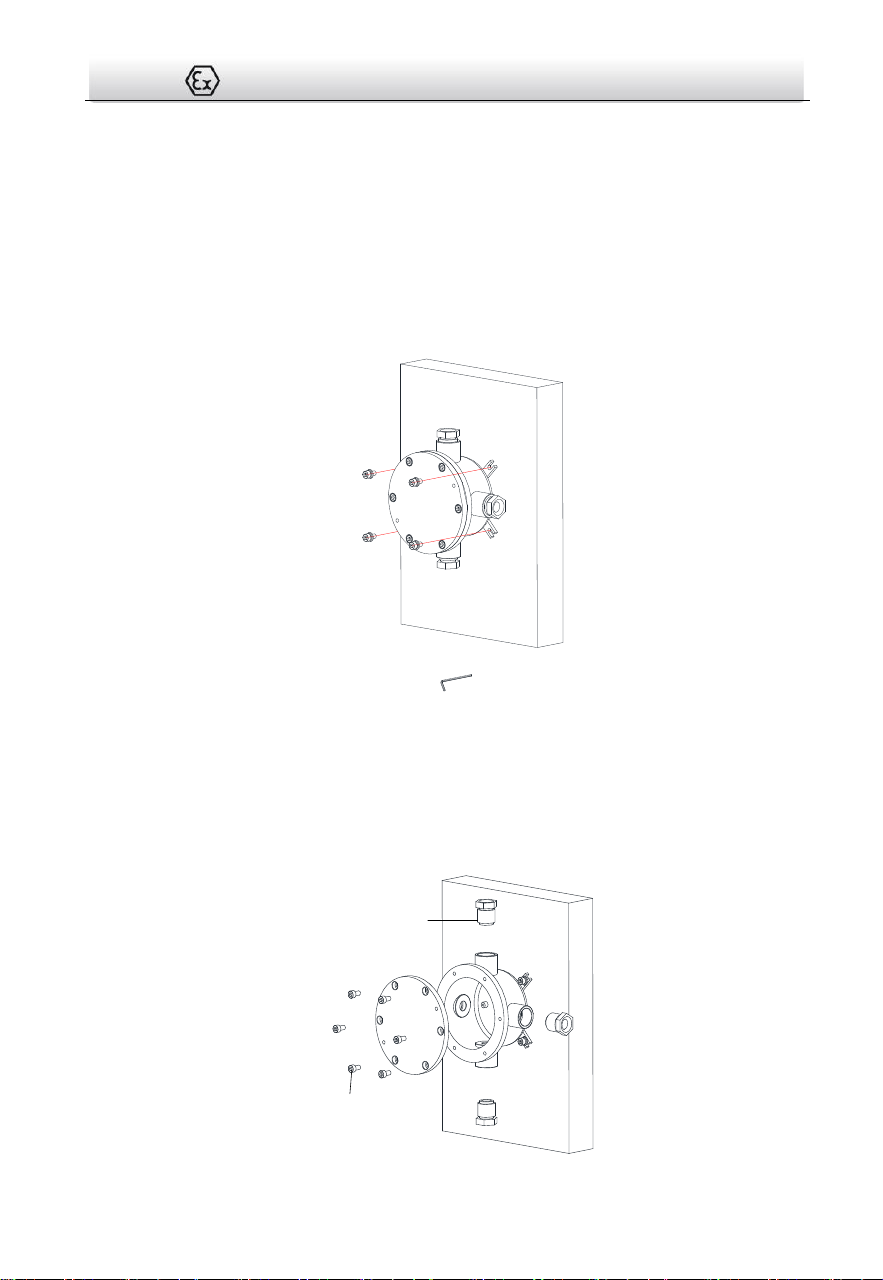
4.5 Explosion-proof control box(ATEX/IECEx
certificates ) Installation (without fiber)
Steps:
1. Attach the junction box onto the wall, and mark the four screw sites with pencil.
2. Drill four φ8 screw holes on the wall.
3. Use the Allen wrench to secure the junction box on the wall with four M8 * 80
expansion screws.
4. Place gasket and screw the nuts.
Figure 1-8 Secure the Junction Box
5. Loosen the screws to disassemble the junction box cover and keep the cover aside.
Note:
● Do not take out the safety rope.
● Be careful to protect the cover of junction box from damage.
6. Loosen the cable glands and keep the glands aside.
Cable Gland
Screw

Thermal Network Positioning System·Quick Start Guide
13
Figure 1-9 Disassemble the Junction Box
7. Connect the cables.
1). Route the camera cables through the top cable gland and insert them into the
junction box.
2). Route the external cables through the bottom cable gland and insert them into the
junction box.
3). Poke through the sealing ring, and use the sealing rings to cover the cables.
4). Connect the power cables with the connector, and then connect the video cables.
Sealing Ring
Top Cable
Gland
Sealing Ring
Bottom
Cable Gland
Figure 1-10 Connect Cables
8. Connect the junction box and explosion-proof tube with cable glands.
9. Cover the junction box with the screws.
Figure 1-11 Cover the Junction Box

Thermal Network Positioning System·Quick Start Guide
14
Result:
The Installation is complete, see the figure below.
Figure 1-12 Installation Complete
4.6 Explosion-proof control box(ATEX/IECEx
certificates ) Installation (with fiber)
For type DS-2TD□TF-□,Refer to Figure 1-13,must use galvanized steel pipe to protect
optical fiber strongly. Figure shown as Explosion-proof control box. If necessary, the free
end of the composite cable should be taken into the inside of the end-equipment
enclosure that is Ex apparatus, or safety area.
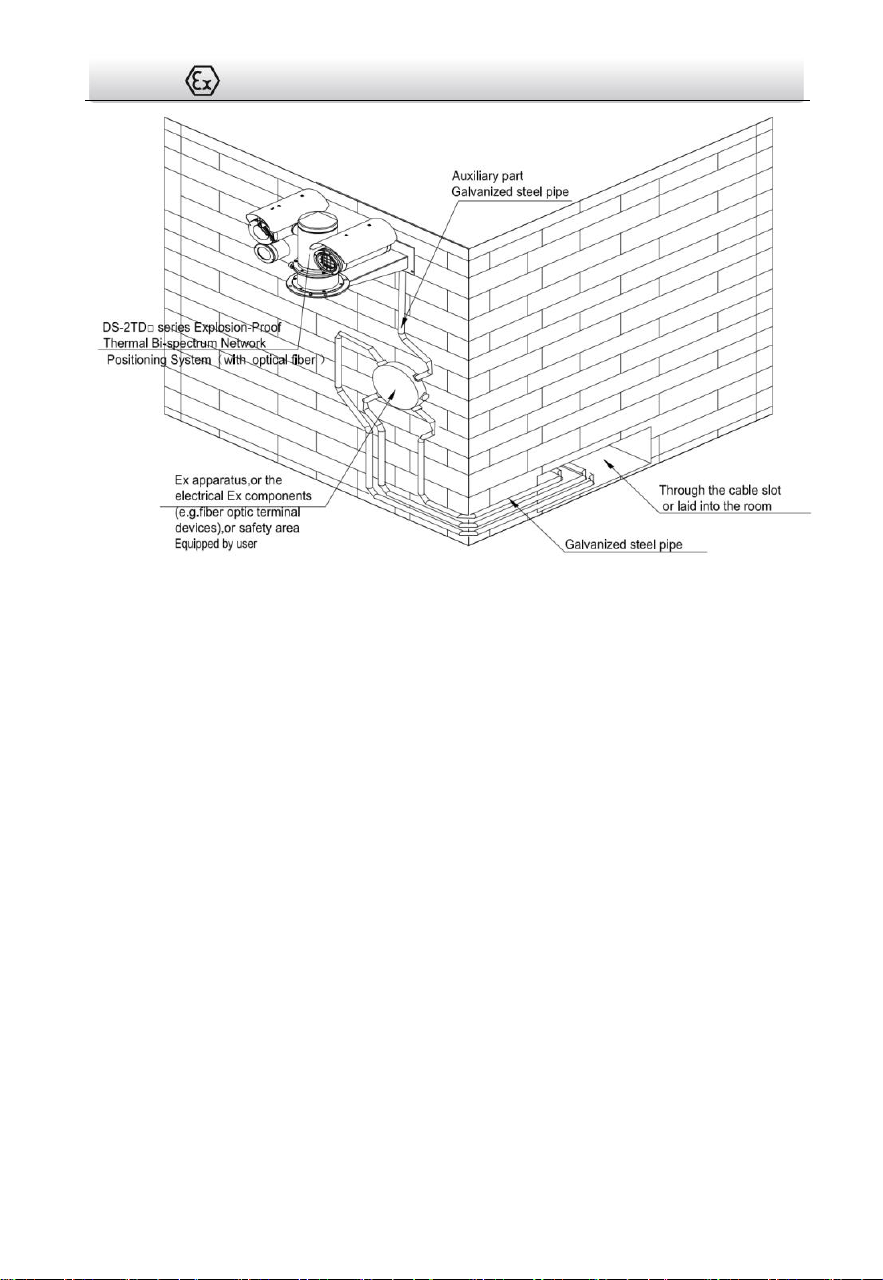
Thermal Network Positioning System·Quick Start Guide
15
Figure 1-13 Installation Complete With Optical Fiber Model
4.7 Finishing Installing
Connect the corresponding cables and turn the power on; the system will do the
self-test automatically. Make sure the live view image and the PTZ control work
normally and then finish the installation.

Thermal Network Positioning System·Quick Start Guide
16
5 Setting the System over the LAN
You shall acknowledge that the use of the product with Internet access might be
under network security risks. For avoidance of any network attacks and
information leakage, please strengthen your own protection. If the product does
not work properly, please contact with your dealer or the nearest service center.
To ensure the network security of the positioning system, we recommend you to
have the system assessed and maintained termly. You can contact us if you need
such service.
5.1 Wiring
To view and configure the system via LAN (Local Area Network), you need to connect the
network system in the same subnet with your PC. Then, install the SADP or client
software to search and change the IP of network system.
The following figure shows the cable connection of network system.
Network Positioning
System
Switch
Internet
NVR
PC
Figure 5-1 Wiring over LAN
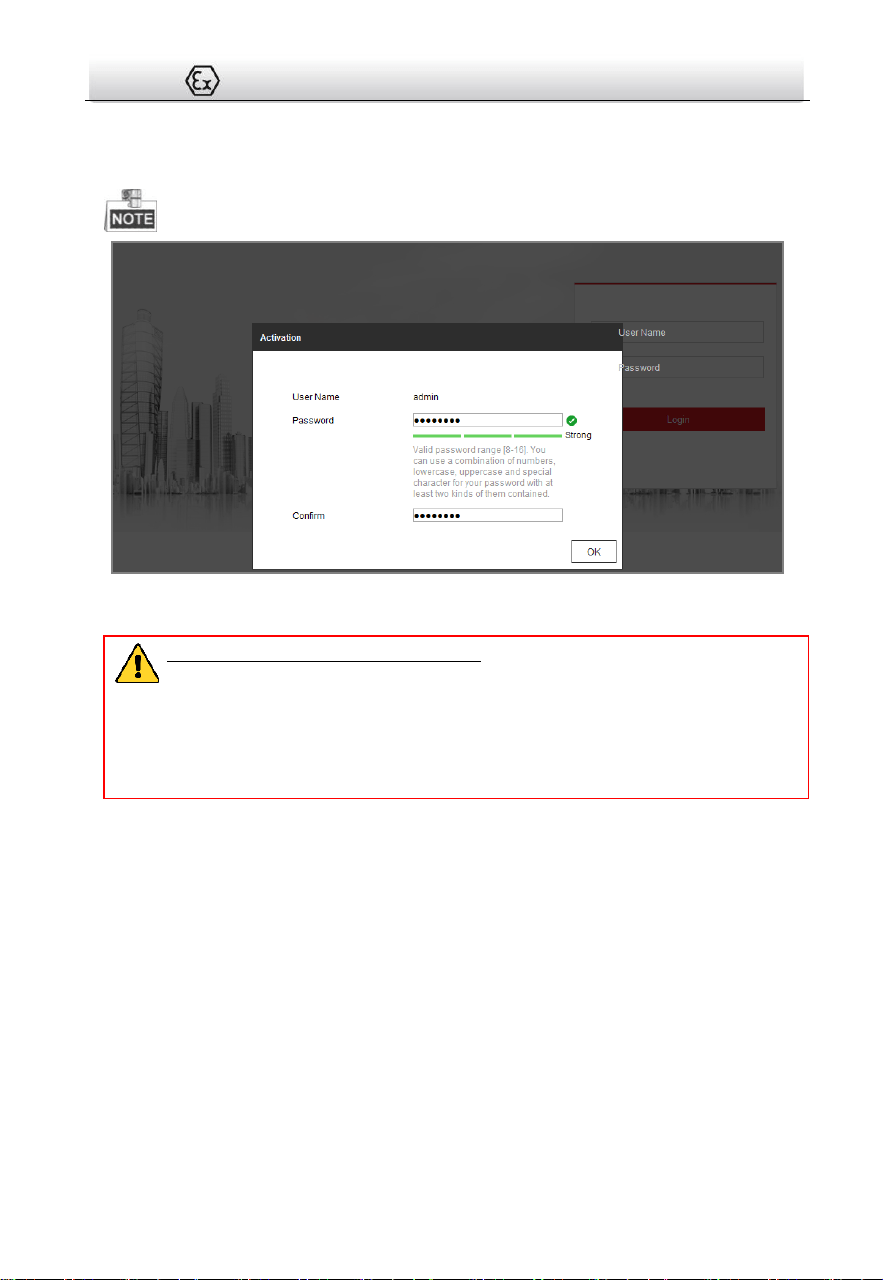
5.2 Activating the System
Purpose:
You are required to activate the system first by setting a strong password for it before
you can use the system.
Activation via Web Browser, Activation via SADP, and Activation via client software are
supported. In the following sections, activation via web browser and SADP will be taken
as examples. You may refer to the user manual of the system for the details of activation
via client software.
5.2.1 Activation via Web Browser
Steps:
Thermal Network Positioning System·Quick Start Guide
17
6. Power on the system, and connect the system to the network.
7. Input the IP address into the address bar of the web browser, and click Enter to enter
the activation interface.
The default IP address of the system is 192.168.1.64.
Figure 5-2 Activation Interface(Web)
8. Create a password and input the password into the password field.
STRONG PASSWORD RECOMMENDED– We highly recommend you create a
strong password of your own choosing (using a minimum of 8 characters,
including upper case letters, lower case letters, numbers, and special
characters) in order to increase the security of your product. And we
recommend you reset your password regularly, especially in the high security
system, resetting the password monthly or weekly can better protect your
product.
9. Confirm the password.
10. Click OK to activate the system and enter the live view interface.
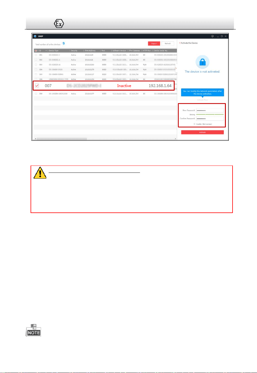
5.2.2 Activation via SADP Software
SADP software is used for detecting the online device, activating the device, and
resetting the password.
Get the SADP software from the supplied disk or the official website, and install the
SADP according to the prompts. Follow the steps to activate the system.
Steps:
1. Run the SADP software to search the online devices.
2. Check the device status from the device list, and select an inactive device.
Thermal Network Positioning System·Quick Start Guide
18
Select inactive device.
Input and confirm
password.
Figure 5-3 SADP Interface
3. Create a password and input the password in the password field, and confirm the
password.
STRONG PASSWORD RECOMMENDED– We highly recommend you create a
strong password of your own choosing (using a minimum of 8 characters,
including upper case letters, lower case letters, numbers, and special
characters) in order to increase the security of your product. And we
recommend you reset your password regularly, especially in the high security
system, resetting the password monthly or weekly can better protect your
product.
4. Click OK to save the password.
You can check whether the activation is completed on the popup window. If activation
failed, please make sure that the password meets the requirement and then try again.
5.3 Modifying the IP Address
Purpose:
To view and configure the system via LAN (Local Area Network), you need to connect the
network system in the same subnet with your PC. Then, install the SADP software or
client software to search and change the IP of network system. We will take modifying
the IP Address via SADP software as an example to introduce the IP address
modification.
Steps:
1. Run the SADP software.
2. Click to select an active device.
Please refer to section 3.2 to activate the system if it is inactive.

Thermal Network Positioning System·Quick Start Guide
19
3. Change the device IP address to the same subnet with your computer by either
modifying the IP address manually or checking the checkbox of Enable DHCP.
Figure 5-4 Modify the IP Address
4. Input the password and click Save to activate your IP address modification.

Thermal Network Positioning System·Quick Start Guide
20
6 Operating via Web browser
6.1 Accessing the System
System Requirement:
Operating System: Microsoft Windows XP SP1 and above version / Vista / Win7 /
Server 2003 / Server 2008 32bits
CPU: Intel Pentium IV 3.0 GHz or higher
RAM: 1G or higher
Display: 1024×768 resolution or higher
Web Browser: Internet Explorer 7.0 and above version, Apple Safari 5.02 and above
version, Mozilla Firefox 5 and above version and Google Chrome8 and above version
Steps:
1. Open the web browser.
2. In the browser address bar, input the IP address of the network positioning system,
e.g., 192.168.1.64 and press the Enter key to enter the login interface.
3. Activate the positioning system for the first time using, refer to the section 5.2
Activating the System.
4. Input the user name and password and click .
The admin user should configure the device accounts and user/operator
permissions properly. Delete the unnecessary accounts and user/operator
permissions.
The device IP address gets locked if the admin user performs 7 failed password
attempts (5 attempts for the user/operator).

Thermal Network Positioning System·Quick Start Guide
21
Figure 6-1 Login Interface
5. Install the plug-in before viewing the live video and managing the network
positioning system. Please follow the installation prompts to install the plug-in.
You may have to close the web browser to finish the installation of the plug-in.
Figure 6-2 Download Plug-in
6. Reopen the web browser after the installation of the plug-in and repeat the above
steps 2-4 to login.
For detailed instructions of further configuration, please refer to the user
manual of network positioning system.
6.2 Live View Page
The live video page allows you to view live video, capture images, realize PTZ control,
set/call presets and configure video parameters.

Thermal Network Positioning System·Quick Start Guide
22
Live View
Parameters
Live View Window
Toolbar
Show or hide
PTZ control
panel
PTZ Control
Preset/ Patrol/Pattern
Menu Bar
Figure 6-3 Live View Page
Menu Bar:
Click each tab to enter Live View, Playback, Picture, and Configuration page
respectively.
Click to display the help file of the positioning system.
Click to logout the system.
Live View Window:
Display the live video.
Toolbar:
Operations on the live view page, e.g., live view, capture, record, audio on/off,
regional exposure, regional focus, etc.
PTZ Control:
Panning, tilting, focusing and zooming actions of the positioning system. The lighter,
wiper, one-touch focus and lens initialization control.
Preset/patrol/pattern:
Set and call the preset/patrol/pattern for the positioning system.

Thermal Network Positioning System·Quick Start Guide
23
Appendix
Frequently Asked Questions (FAQ)
Device Running Error
Question:
The device fails to start up or reboots repeatedly.
The device constantly powers off unexpectedly when you pan/tilt
the device or call preset.
The device fails to zoom in/out or pan/tilt.
Answer:
Examine the power supply of the positioning system and see
whether it meets the requirements.
Select the power supply as close as possible.
Examine the power cord and see whether it meets the
requirements.
Device Upgrading
Question:
Device fails to upgrade.
Answer:
Examine if the device upgrading fails because of the poor network.
Examine if the upgrading program matches with the device type.
Others
Question:
The device live view is vague.
Answer:
Examine if you removed the protective film.
Examine if the lens is dirty or not.
Examine if any obstruction is nearby, e.g. spider web.
Question:

Thermal Network Positioning System·Quick Start Guide
24
Live view fails with good network connection.
Answer:
Examine if the IE plug-in is well installed. Change the Website
Blocker settings if necessary.
For cross-domain routing, enable the UPnP of device, or set
manual mapping to port No. 80, 8000, or 554.
Examine if the live view channel amount exceeds the upper limit.
Examine the network bandwidth.
Question:
Focus fails when you test outdoor device in indoor situation.
Answer:
Restore the device to default settings.
Adjust the Min. Focusing Distance in Configuration > Image>
Display Settings > Focus

Thermal Network Positioning System·Quick Start Guide
25
Common Material Emissivity Reference
Material
Emissivity
Human Skin
0.98
PCB
0.91
Cement Concrete
0.95
Ceramics
0.92
Rubber
0.95
Paint
0.93
Wood
0.85
Asphalt
0.96
Brick
0.95
Sand
0.90
Soil
0.92
Cotton
0.98
Cardboard
0.90
White Paper
0.90
Water
0.96

UD25684B-A


