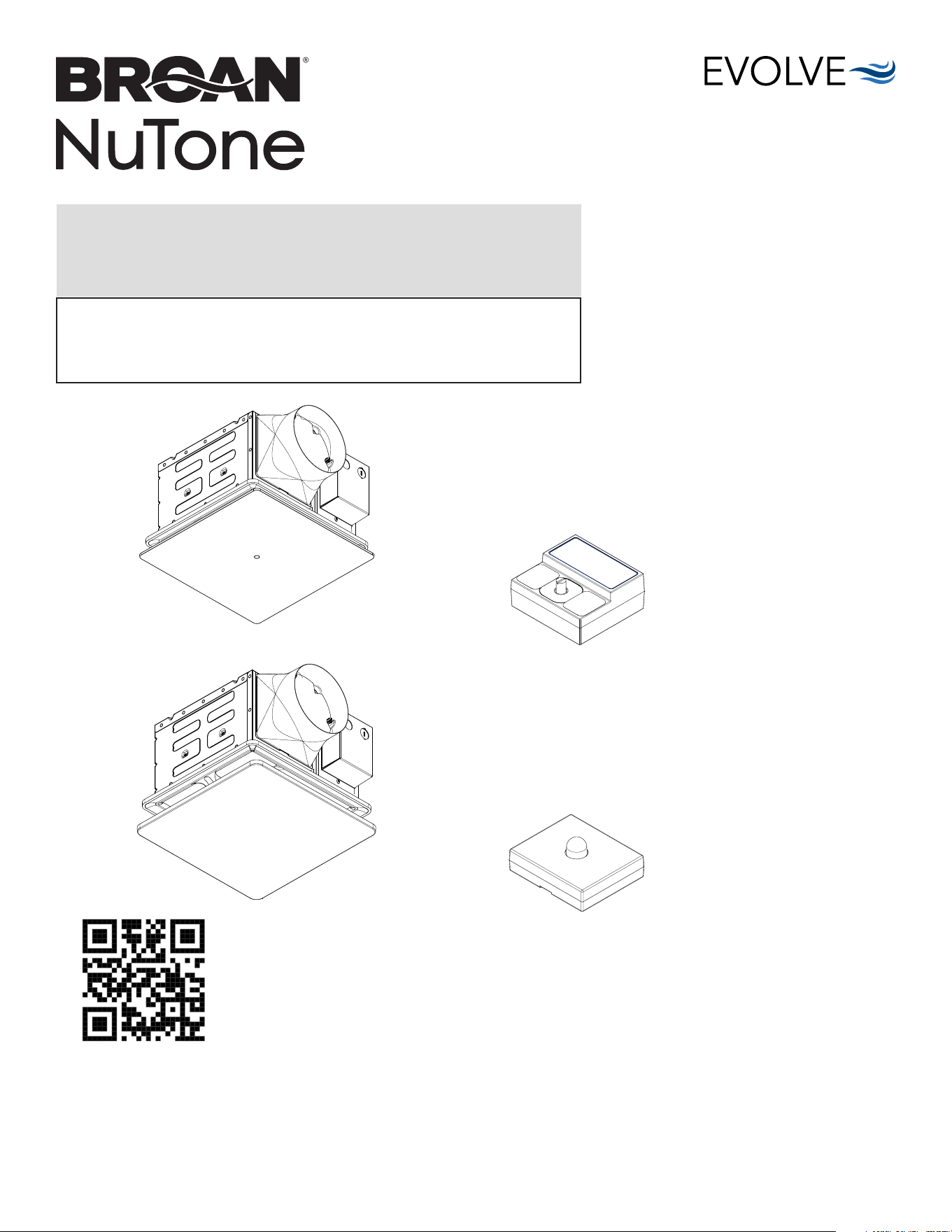
PTE511RK:
50-80-110 Selectable CFM
with Continuous Run Fan
PTEL511RK:
50-80-110 Selectable CFM
with Continuous Run Fan/Light
PTE1115RK:
110-130-150 Selectable CFM
with Continuous Run Fan
PTEL1115RK:
110-130-150 Selectable CFM
with Continuous Run Fan/Light
PES: Humidity Sensing Module
PEM: Motion Sensing Module
(available only with PTE511RK and
PTE1115RK models)
READ AND SAVE THESE INSTRUCTIONS
Installer: leave this guide with homeowner.
Register your product online at www.broan-nutone.com/register.
Easy installation in both
new construction and retrofit
Table of Contents
Warnings and Cautions 2
Typical Installation 2
Preparation 3
New Construction/Retrofit Installation 4
New Construction Installation 5
Retrofit Installation 6
New Construction/Retrofit Installation 7
Operation 12
Cleaning and Maintenance 13
Troubleshooting 13
© 2024 Broan
INSTALLATION GUIDE
PTE1115RK
PTEL1115RK
PEM
PES
Scan this QR code for helpful hints.
For Warranty Statement, Service Parts, Technical Support, or to Register your product, please
visit our website or call:
In the United States - Broan-NuTone.com 800-558-1711.
In Canada - Broan-NuTone.ca 800-567-3855.
PTE511RK
n
PTE1115RK
n
PTEL511RK
n
PTEL1115RK Installation Guide
Page 2
WARNING
TO REDUCE THE RISK OF FIRE, ELECTRIC SHOCK, OR
INJURY TO PERSONS, OBSERVE THE FOLLOWING:
1. Use this unit only in the manner intended by the manufacturer.
If you have questions, contact the manufacturer at the address
or telephone number listed in the warranty.
2. Acceptable for use over a tub or shower (PTE511RK and
PTE1115RK models only) when connected to a GFCI (Ground
Fault Circuit Interrupter) - protected branch circuit.
3. Ducted fans must always be vented to the outdoors.
4. Use only ON/OFF switch, mechanical timer or relay-switched
control.
5. Before servicing or cleaning unit, switch power off at service
panel and lock the service disconnecting means to prevent
power from being switched on accidentally. When the service
disconnecting means cannot be locked, securely fasten a
prominent warning device, such as a tag, to the service panel.
6. Installation work and electrical wiring must be done by a
qualified person(s) in accordance with all applicable codes
and standards, including fire-rated construction codes and
standards.
7. Sufficient air is needed for proper combustion and exhausting
of gases through the flue (chimney) of fuel burning equipment
to prevent backdrafting. Follow the heating equipment
manufacturer’s guideline and safety standards such as those
published by the National Fire Protection Association (NFPA),
and the American Society for Heating, Refrigeration and
Air Conditioning Engineers (ASHRAE), and the local code
authorities.
8. When cutting or drilling into wall or ceiling, do not damage
electrical wiring and other hidden utilities.
9. This unit must be grounded.
10. Do not use replacement parts that have not been recommended
by the manufacturer (e.g. parts made at home using a 3D
printer).
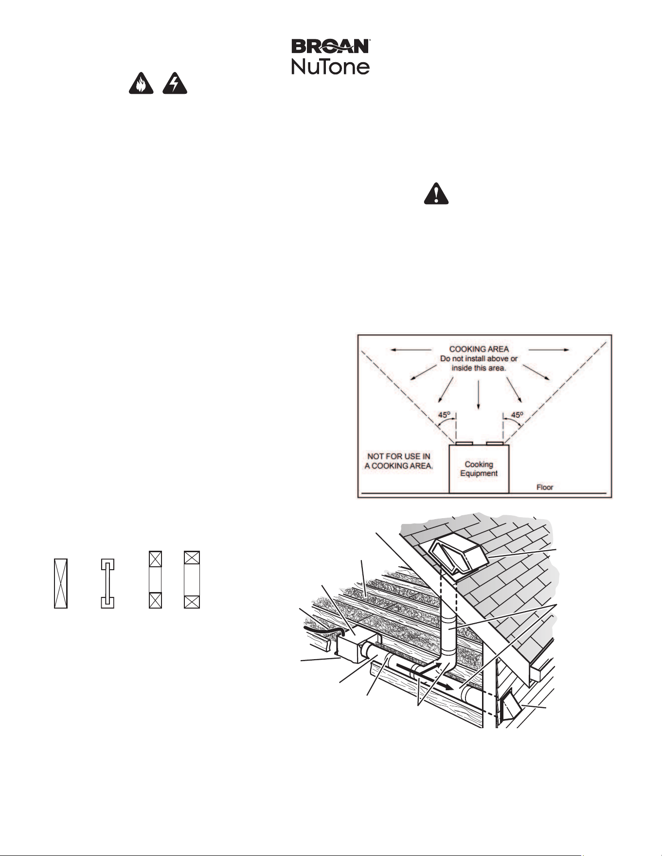
Typical Installation
CAUTION
1. For general ventilating use only. Do not use to exhaust
hazardous or explosive materials and vapors.
2. This product is designed for installation in ceilings up to a
12/12 pitch (45 degree angle). Duct connector must point up.
DO NOT MOUNT THIS PRODUCT IN A WALL.
3. To avoid motor bearing damage and noisy and/or unbalanced
impellers, keep drywall spray, construction dust, etc. off power
unit.
4. Please read specification label on product for further
information and requirements.
• Installation is the same for:
• Fits in 2" x 8" ceiling construction.
• Infinitely adjust the fan position
between joists from 14" to 24"
on center.
• Can be installed between joists or
trusses if the distance between them
is 10½".
• Do not install this fan in a ceiling
thermally insulated to a value greater
than R40.
*Purchase
separately.
INSULATION*
(Place around and
over Fan Housing.)
ROOF CAP*
(with built-in
damper)
FAN
HOUSING
POWER
CABLE*
ROUND
DUCT*
ROUND
ELBOWS*
Seal gaps
around
Housing.
Seal duct
joints with
tape.
OR
Keep duct
runs short.
WALL CAP*
(with built-in
damper)
Joists I-Joists Trusses
The ducting from this fan to the outside of the building has a strong effect on the air flow, noise and
energy use of the fan. Use the shortest, straighest duct routing possible for best performance,
and avoid installing the fan with smaller ducts than recommended. Insulation around the ducts
can reduce energy loss and inhibit mold growth. Fans installed with existing ducts may not
achieve their rated airflow.
6-inch round rigid metal duct is recommended for best performance.
11. Monitor your fan for unusual sounds, smells and smoke. If any
appear, turn off the fan immediately and replace it.
12. When performing service, maintenance and installation work,
gloves and safety glasses are recommended.
13. Do not use this fan with any solid-state speed control device.
PTE511RK
n
PTE1115RK
n
PTEL511RK
n
PTEL1115RK Installation Guide
Page 3
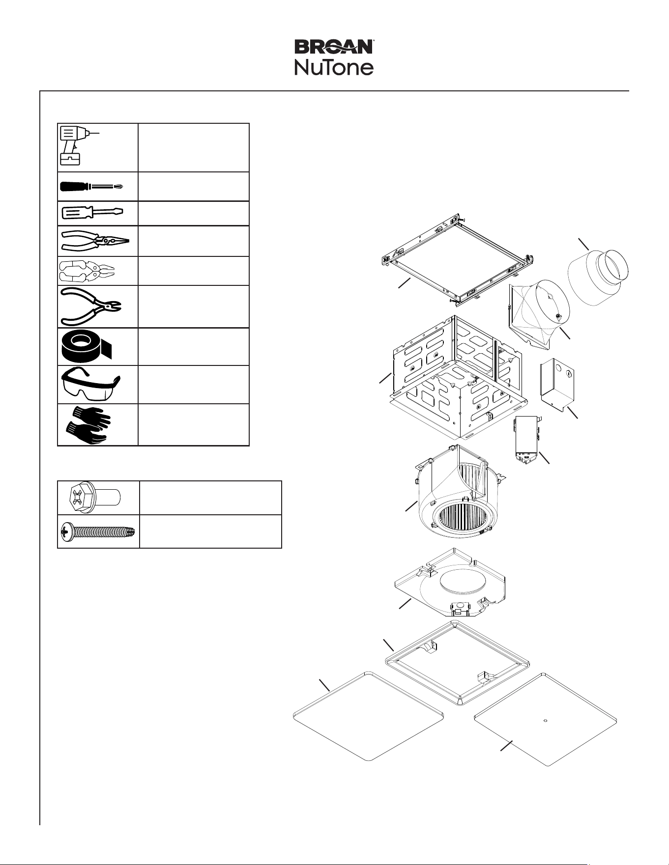
Preparation
Tools Needed Materials Needed
• 6" round metal ducting for PTE1115RK and PTEL1115RK models
• 4” round metal ducting for PTE511RK and PTEL511RK models
• Roof cap or wall cap (built-in damper recommended)
• Electrical wiring and supplies per local code requirements
Power screwdriver
with a Phillips bit
Phillips screwdriver
Flathead screwdriver
Pliers
Wire insulation stripper
Wire cutter
Foil tape
Safety glasses
Safety gloves
Fan Main Parts
Parts Bag Content
Mounting Frame
Housing
Blower
Muffler Plate
Trim Cover
Fan Lit Grille
Fan Only Grille
Controller
Power Box
6" Duct
Connector
4" Duct
Reducer
5 X Phillips Hex Head Screw
2 X Phillips Pan Head Screw
PTE511RK
n
PTE1115RK
n
PTEL511RK
n
PTEL1115RK Installation Guide
Page 4
New Construction/Retrofit Installation
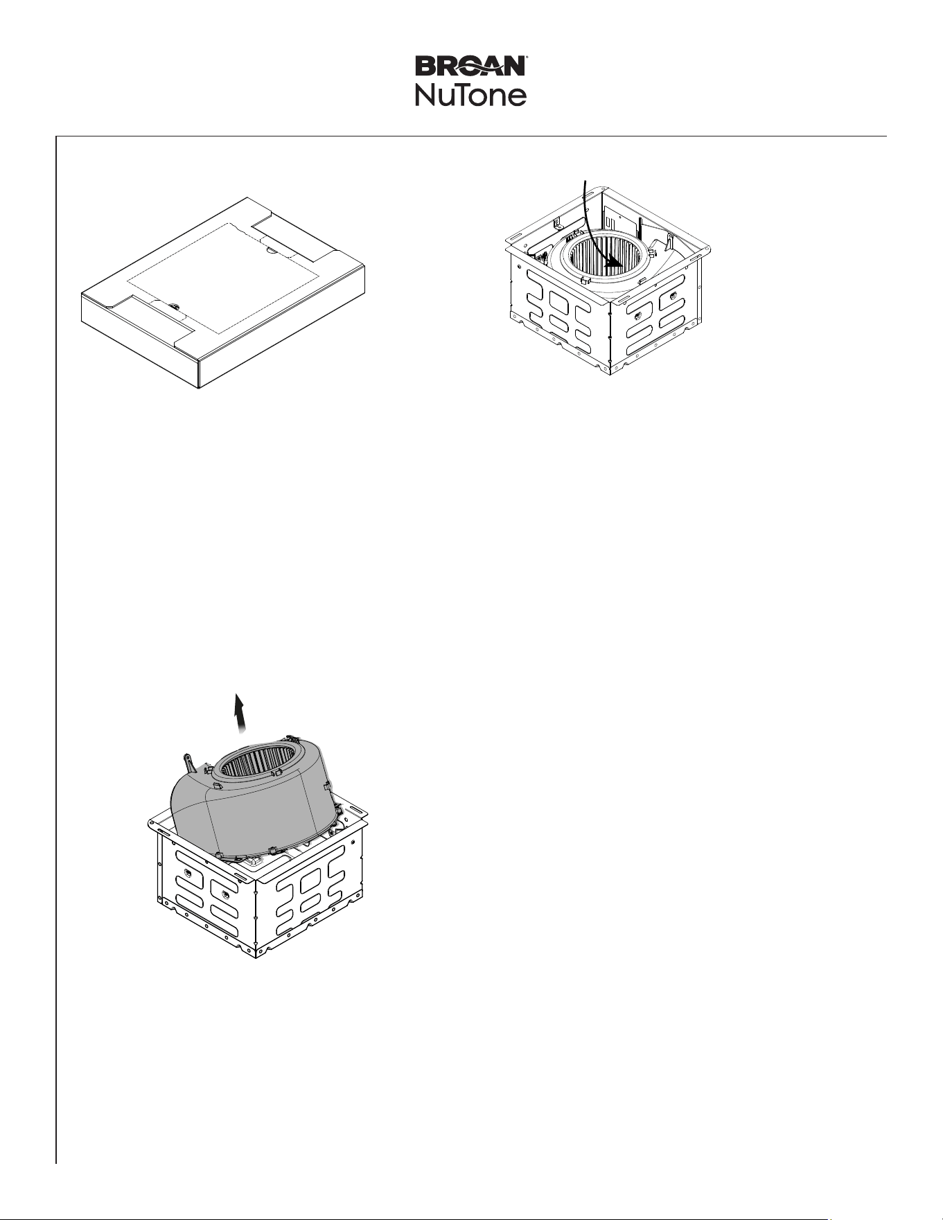
1
Remove Packaging
2
Remove Blower
Assembly
• Slide the Blower Assembly. Tilt the Blower Assembly.
• Remove and set aside the Blower Assembly.
Remove
Parts Bag from
Blower.
Remove
Grille from Grille Filler.
Lit Models Only:
Remove Jumper
Cable from Grille
Filler.
Tilt blower to
clear metal tabs.
PTE511RK
n
PTE1115RK
n
PTEL511RK
n
PTEL1115RK Installation Guide
Page 5
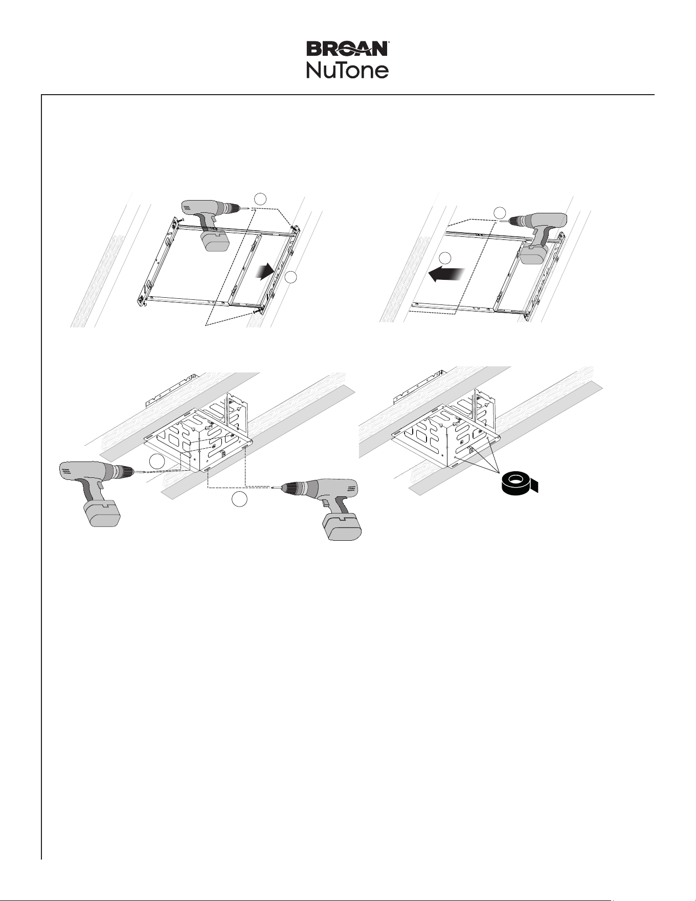
New Construction Installation
3
Mount Housing
NOTE: Use 4 screws preattached to mounting frame to mount to
joist.
Using Mounting Frame (Recommended Installation)
Directly to Joist (Alternate Installation)
1
2
NOTE: Use 4 screws preattached to mounting frame to mount to joist.
1
2
4
3
Mount the frame 1/2" above the bottom of the joist. Housing flange should be level with the joist when installed.
Make sure UP
on the mounting
frame is oriented
correctly.
NOTE: If using alternate
installation method
without mounting frame,
tape off mounting frame
holes on the housing,
on both sides, using
foil tape to prevent air
leakage.
PTE511RK
n
PTE1115RK
n
PTEL511RK
n
PTEL1115RK Installation Guide
Page 6
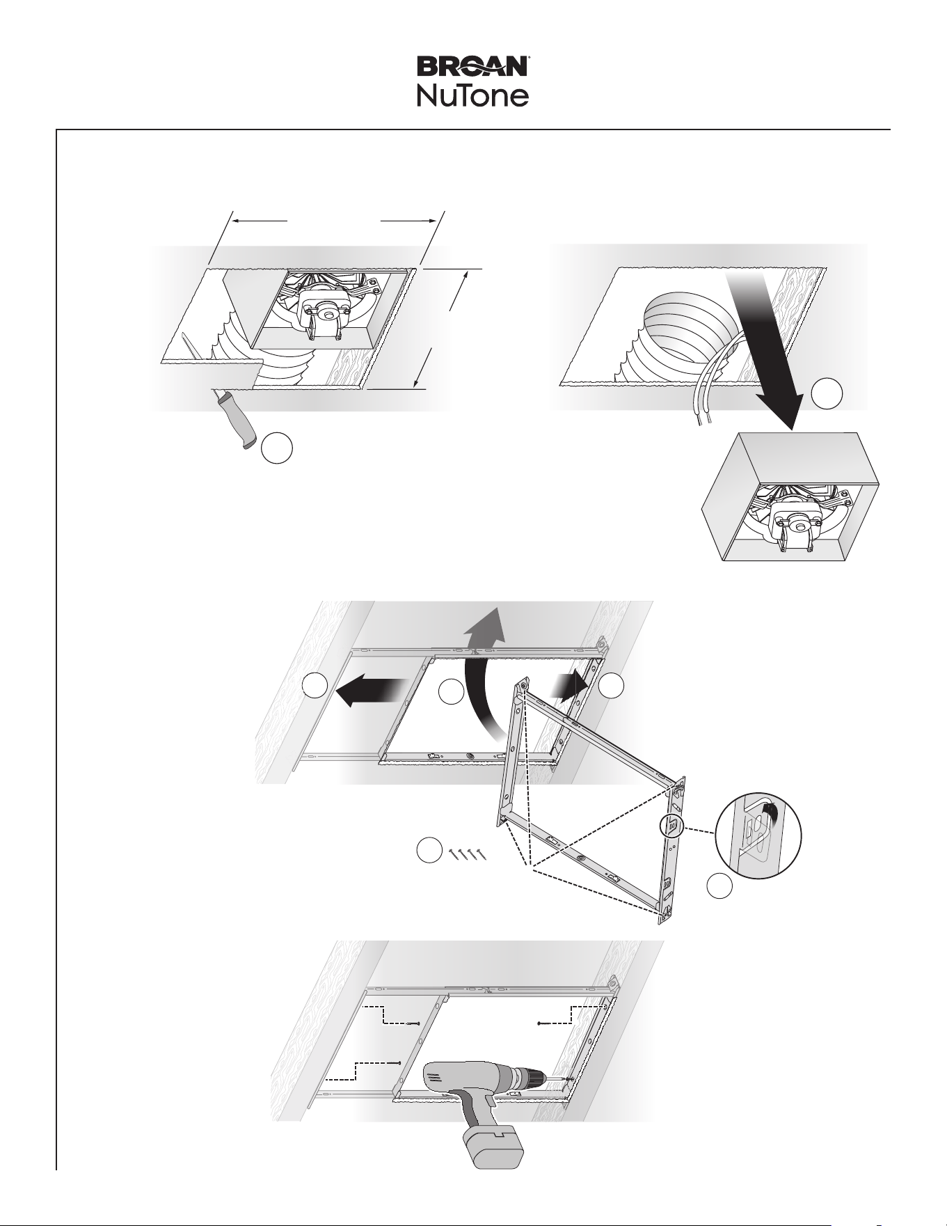
Retrofit Installation
12" (30.5 cm)
1
2
Existing ductwork and
wiring left in place
11" (27.9 cm)
parallel with joists
Examine the existing wiring to make sure it is not damaged. If any damage is found,
DO NOT CONTINUE INSTALLATION of this product. Contact a qualified person(s) for repair.
2
Examine Wiring
1
Enlarge Ceiling Opening and Remove Existing Fan
1
2
3
4
5
3.1
Insert
Mounting
Frame
Bend up
four tabs.
Remove screws from
Mounting Frame
and set aside.
NOTE: Skip this
step if the space
between joists or
trusses is 10½".
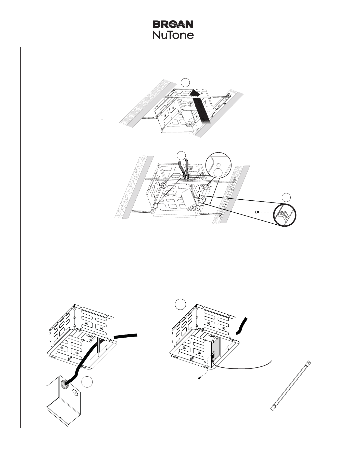
3.2
Secure
Mounting
Frame
Screws set
aside
in Step 3.1
PTE511RK
n
PTE1115RK
n
PTEL511RK
n
PTEL1115RK Installation Guide
Page 7
New Construction/Retrofit Installation
1
3
4
2
4
Snap-in and
Secure Housing
Position Housing
between joists and
crimp channel on both
sides of Mounting Frame
to lock Housing in place.
Do not crimp Housing.
snap!
Secure Housing on
both sides using 2
screws per bracket.
Screw from
Parts Bag
5
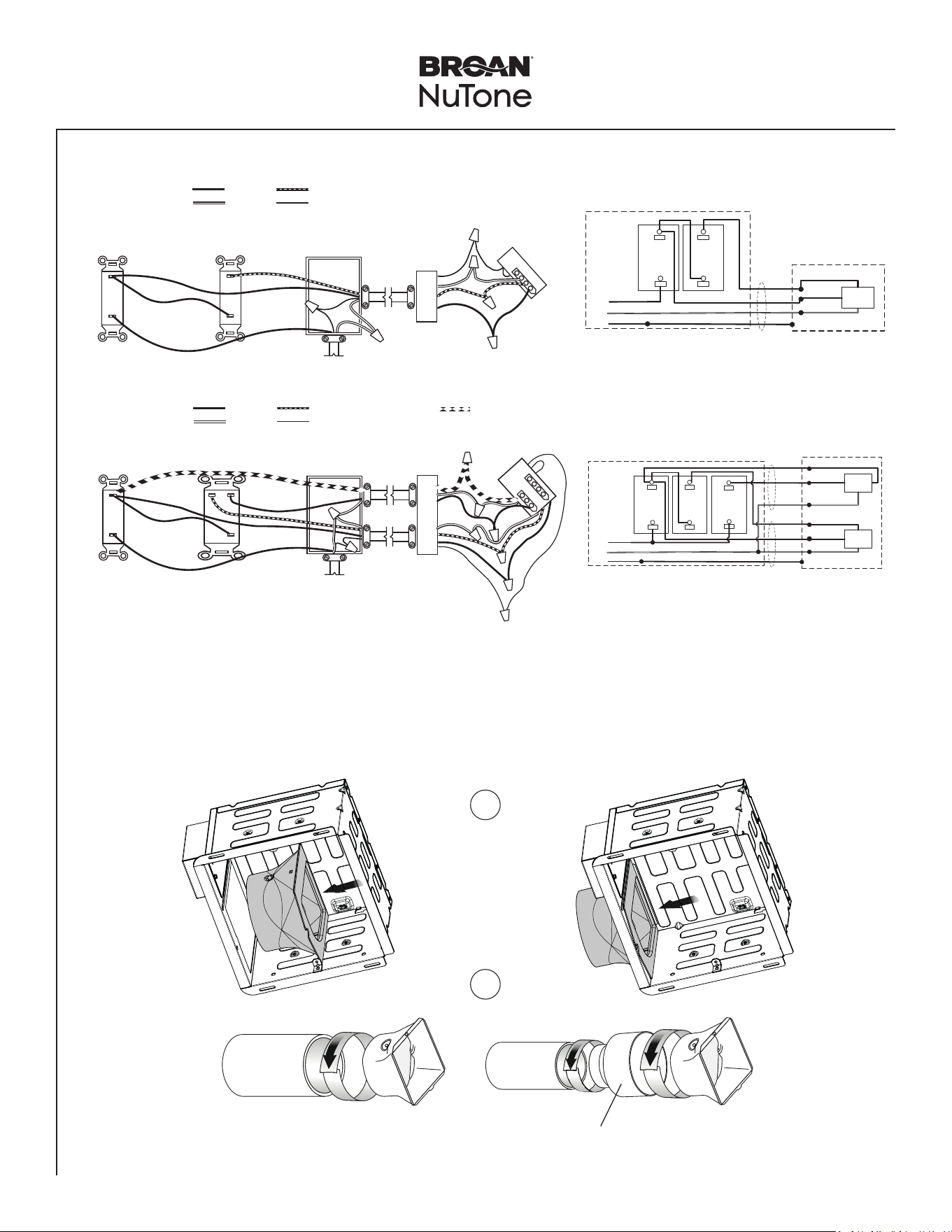
Insert Power Box into Housing
1
1- Run 120 VAC electrical wiring to the installation location.
2- Attach cable clamp to the Power Box.
3- Secure house wiring using cable clamp.
4- Connect wires on power panel to 120 VAC as shown in wiring diagram.
5- Assemble the Power Panel to the Power Box. Secure Power Panel using provided screw.
2
NOTE: Second knockout plate
used for lit models.
NOTE: If installing the lit model,
connect jumper cable to
wire panel.
PTE511RK
n
PTE1115RK
n
PTEL511RK
n
PTEL1115RK Installation Guide
Page 8
BOOST
SWITCH
(purchase separately)
POWER
BOX
120 VAC LINE IN
SWITCH BOX
BLACK
WHITE GROUND (green or bare)
RED
CONTROL
SWITCH
(purchase separately)
Do not use a
speed control.
POWER
PANEL
14/4
2-FUNCTION
BOOST & TASK LIGHT
(purchase separately)
POWER
BOX
120 VAC LINE IN
SWITCH BOX
BLACK
WHITE GROUND (green or bare)
RED
CONTROL SWITCH
(purchase separately)
Do not use a
speed control.
POWER
PANEL
BLUE
14/3
14/4
New Construction/Retrofit Installation
PTE511RK - PTE1115RK
PTEL511RK - PTEL1115RK
FAN
BLK
WHT
WHT
GRD
GRD
SWITCH BOX
UNIT
LINE
IN
WHT
REDRED
REDRED
14/4
BOOST
SWITCH
CONTROL
SWITCH
BLK
BLK
FAN
BLK
WHT
WHT
GRD
GRD
SWITCH BOX
UNIT
LINE
IN
LIGHT
WHT
WHT
BLUBLU
REDRED
REDRED
BLK
WHT
14/3
14/4
TASK LIGHT/
DIMMER
SWITCH
BOOST
SWITCH
CONTROL
SWITCH
BLK
BLK
BLKBLK
TapeTape
Tape6" Ducting
4" Ducting
6
Insert Duct Connector and Attach Ducting
1
2
NOTE: 6" duct connector provided with 110-130-150 Selectable
CFM models PTE1115RK and PTEL1115RK.
NOTE: 6" duct connector and 4" reducer provided with 50-80-110
Selectable CFM models PTE511RK and PTEL511RK.
PTE511RK
n
PTE1115RK
n
PTEL511RK
n
PTEL1115RK Installation Guide
Page 9
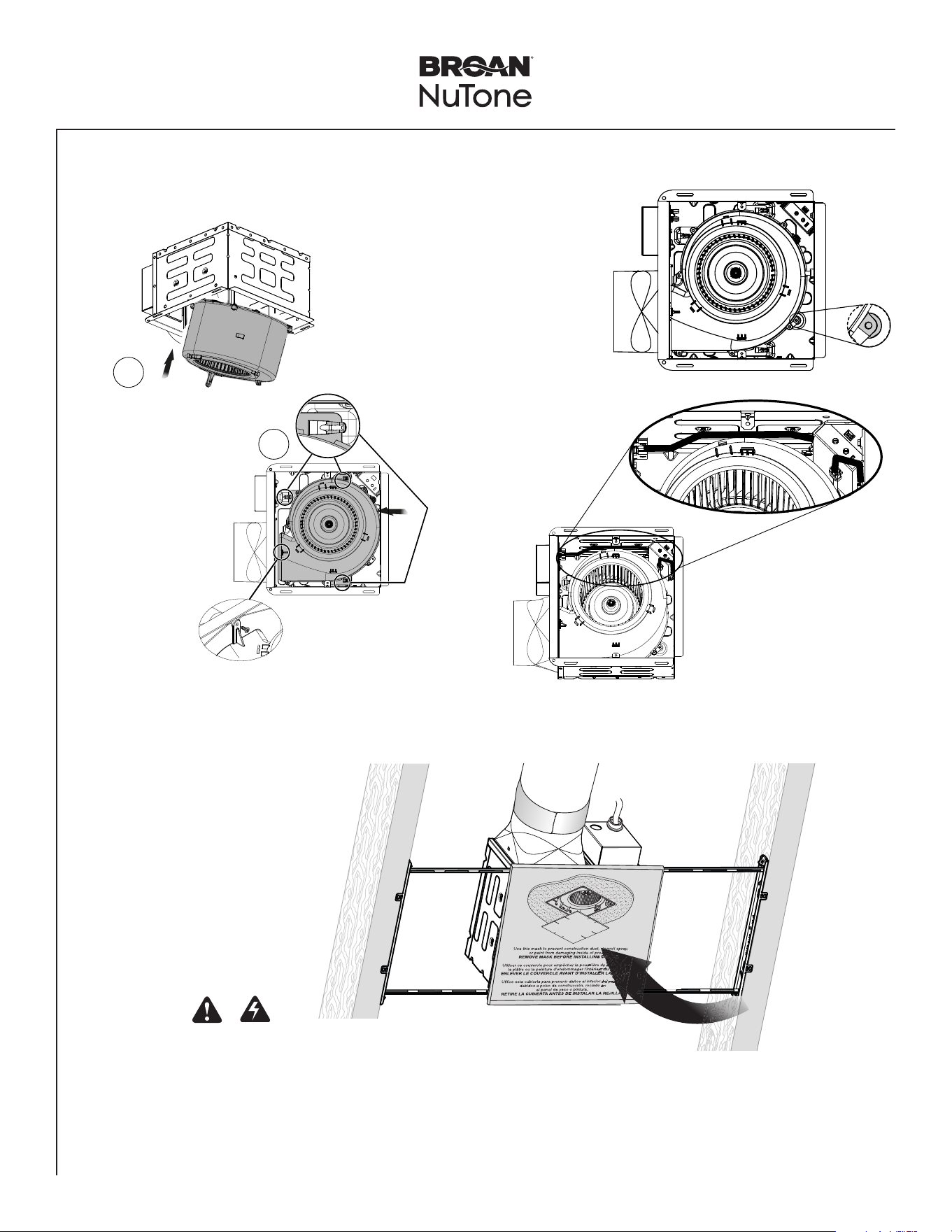
7
Insert Blower in Housing
Slide the
Blower until it
is engaged at 3
places
inside Housing.
1
2
click!
New Construction/Retrofit Installation
Secure blower in place
using screw from parts bag.
NOTE: Make wire connections
after installing blower.
Adjust fan settings on
controller for boost
airflow, low speed
continuous airflow and
time delay.
E
Tilt blower to
clear metal tabs.
D
Install blower
plate mounting
screw for
recommended
installation.
8
Insert Mask and
Finish Ceiling
Mask protects unit
during construction.
Remove before
installing Grille.
• Install ceiling material.
• Cut out around Housing.
CAUTION
If the blower was unplugged, power must be
disconnected (see page 2, WARNING item 5)
before inserting motor plugs into control assembly.
IN ORDER TO PREVENT MOTOR/CONTROL DAMAGE:
PTE511RK
n
PTE1115RK
n
PTEL511RK
n
PTEL1115RK Installation Guide
Page 10
New Construction/Retrofit Installation
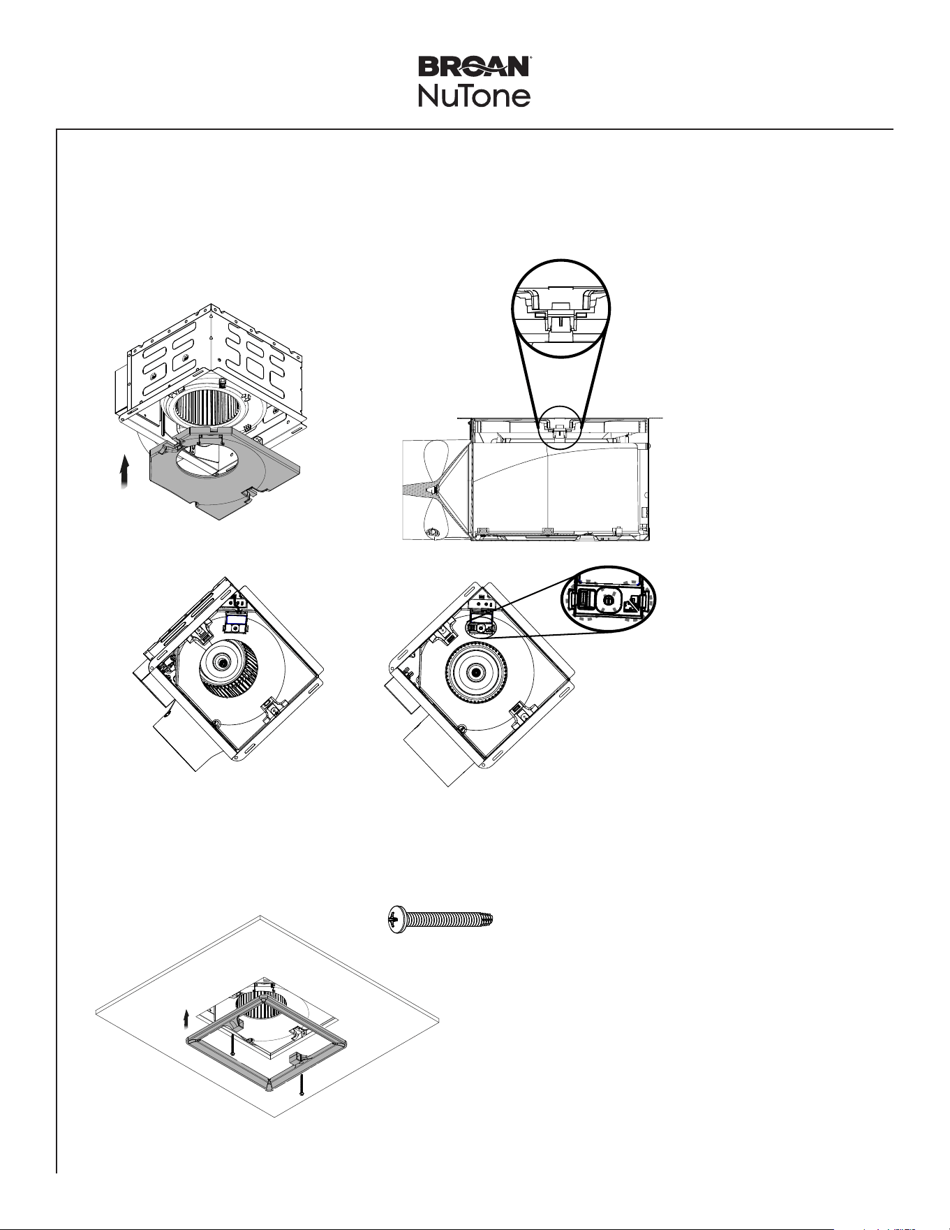
9
Insert Muffler Plate in the Housing
• Insert the Muffler Plate in the Housing. There are two points that muffler plate snaps in.
• If using the Humidity Sensing Module (accessory) - PES (purchase separately), connect the module and snap into the
Muffler Plate.
snap!
PES
NOTE: To remove the muffler
plate, use a flat head
screwdriver to slide
between muffler and
blower snap-in features
to easily detach the
muffler plate from the
blower.
NOTE: Remove the two small
orange stickers.
10
Install the Trim Cover
2 X
NOTE: Install trim cover using a
power screwdriver.
NOTE: Connect the PES
module to the top of the
fan controller.

PTE511RK
n
PTE1115RK
n
PTEL511RK
n
PTEL1115RK Installation Guide
Page 11
New Construction/Retrofit Installation
11
Install Grille
• Slide the grille onto the Trim Cover.
• If using the Motion Sensing Module (accessory) - PEM (purchase separately) remove the cap. Connect the module and
snap to the back of the non-lit Grille. NOTE: this module is not compatible with the fan/light models PTEL511RK and
PTEL1115RK. A motion wall control would need to be used for fan/light models.
1
2
NOTE: For lit models, connect jumper wire to back side of the
grille.
NOTE: Connect motion module to the top
of the fan controller or daisy chain
connecting to PES module.
PTE511RK
n
PTE1115RK
n
PTEL511RK
n
PTEL1115RK Installation Guide
Page 12
WARNING Before servicing or cleaning unit,
switch power off at service panel and lock the service
disconnecting means to prevent power from being
switched on accidentally. When the service disconnecting
means cannot be locked, securely fasten a prominent
warning device, such as a tag, to the service panel.
Operation
To Turn Fan ON
Turn the control switch ON.
It is normal for this ventilation fan to take approximately
5-10 seconds to start running after it is turned on.
• Fan will run at the certified airflow rate if the boost
switch is ON.
• Fan will run at low speed continuous airflow rate if the
boost switch is OFF.
To Use Fan Time Delay Airflow Rate Change
1. Turn the control switch ON.
2. Turn the boost switch ON - fan will run at the certified
airflow rate.
3. When the boost switch is turned OFF, fan will
continue to run at the certified airflow rate until the
user-adjustable time delay has elapsed, and then will
automatically change to the low speed continuous
airflow rate.
To Set the Low Speed Continuous Airflow Rate*
Using a small, flat-blade screwdriver, carefully rotate the
CONTINUOUS RUN adjustment until the arrow points to
the desired airflow rate.
To Set the User-Adjustable Time Delay*
Using a small, flat-blade screwdriver, carefully rotate the
TIME adjustment until the arrow points to the desired time
delay, shown in minutes.
* The user-adjustable controls are located in one corner
of the Fan Housing, behind the Grille.
To Turn Fan OFF
Turn the control switch OFF (sold separately).
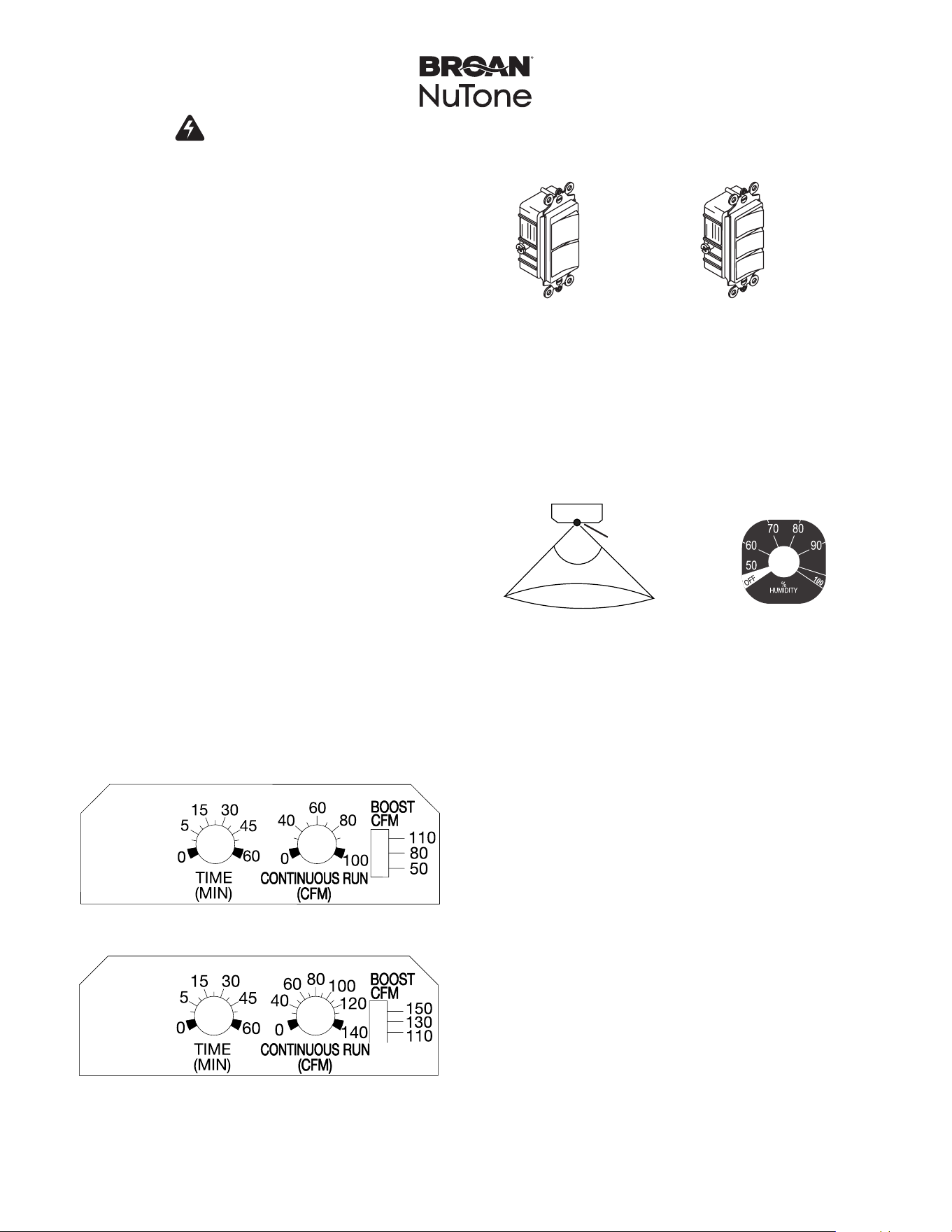
Lighting
Fan/light models are equipped with a main task light
and a night light. The fan and task light can be operated
independently using separate switches. The night light
automatically turns on when the room is dark. There is a
switch on the underside of the grille to deactivate the night
light.
Optional motion (PEM) or humidity sensing (PES)
modules (sold separately)
PTE511RK/PTEL511RK User-adjustable controls
PTE1115RK/PTEL1115RK User-adjustable controls
90º
sensor
10 ft.
PEM Range
PES Range
P2RW P3RW

PTE511RK
n
PTE1115RK
n
PTEL511RK
n
PTEL1115RK Installation Guide
Page 13
1114591A
Cleaning and Maintenance
CAUTION
IN ORDER TO PREVENT MOTOR/CONTROL DAMAGE:
DISCONNECT ELECTRIC POWER SUPPLY AND LOCK
OUT SERVICE PANEL BEFORE SERVICING THE UNIT.
DO NOT remove motor plug to stop spinning motor.
Power must be disconnected (see WARNING at top left of
this page) before motor plug is removed or inserted into
control assembly.
PREVENTIVE MAINTENANCE
For quiet and efficient operation, long life and attractive
appearance, regularly clean the grille and interior of unit.
TO CLEAN THE GRILLE
Remove the grille, use a mild detergent, such as
dishwashing liquid, and dry with a soft cloth. DO NOT
USE ABRASIVE CLOTHS, STEEL WOOL PADS, OR
SCOURING POWDERS.
TO CLEAN INTERIOR OF UNIT
Once the grille is removed, vacuum interior of unit with the
dusting brush attachment.
MAINTENANCE
The motor is permanently lubricated and never needs
oiling. If the unit makes excessive or unusual noises,
replace the blower assembly (includes motor and impeller).
Troubleshooting
Symptom: The fan does not run.
• Check for an open fuse or circuit breaker in the building’s
service panel.
• Check that the two (2) plug-in connections for the Motor
and the Control are seated firmly in place.
• Check that the Blower Wheel spins freely.
Symptom: The fan runs erratically.
• Check that the Blower Wheel is firmly attached to the
Motor shaft and both spin freely.
Symptom: The fan seems noisy.
• Check that the back draft damper in the fan’s Duct
Connector pivots freely. Screws used to attach the duct to
the Duct Connector may be preventing the damper from
opening.
• Check that the back draft damper in the wall or roof cap
pivots freely. These dampers are sometimes mistakenly
painted shut or obstructed by bird and insect debris.
Symptom: The fan does not properly ventilate the room.
• For spot ventilation, turn both the boost switch and the
control switch ON to enable the fan to run at the certified
airflow rate.
• For spot ventilation followed by continuous ventilation,
increase the “TIME” setting of the user-adjustable time
delay.
• For continuous ventilation, increase the “CFM” setting of
the low speed continuous airflow rate.