

AXIS Q1686 - DLE Radar - Video Fusion Camera
T able of Contents
Solution overview . . . . . . . . . . . . . . . . . . . . . . . . . . . . . . . . . . . . . . . . . . . 3
Radar - video fusion . . . . . . . . . . . . . . . . . . . . . . . . . . . . . . . . . . . . . . . . . . . . . . 3
Installation . . . . . . . . . . . . . . . . . . . . . . . . . . . . . . . . . . . . . . . . . . . . . . . . 4
Preview mode . . . . . . . . . . . . . . . . . . . . . . . . . . . . . . . . . . . . . . . . . . . . . . . . . . 4
Considerations . . . . . . . . . . . . . . . . . . . . . . . . . . . . . . . . . . . . . . . . . . . . . . . . . . 4
Radar coverage . . . . . . . . . . . . . . . . . . . . . . . . . . . . . . . . . . . . . . . . . . . . . . . . . 5
Installation examples and use cases . . . . . . . . . . . . . . . . . . . . . . . . . . . . . . . . . 7
Mounting recommendations . . . . . . . . . . . . . . . . . . . . . . . . . . . . . . . . . . . . . . . 10
Get started . . . . . . . . . . . . . . . . . . . . . . . . . . . . . . . . . . . . . . . . . . . . . . . . 12
Find the device on the network . . . . . . . . . . . . . . . . . . . . . . . . . . . . . . . . . . . . 12
Open the device's web interface . . . . . . . . . . . . . . . . . . . . . . . . . . . . . . . . . . . . 12
Create an administrator account . . . . . . . . . . . . . . . . . . . . . . . . . . . . . . . . . . . 12
Secure passwords . . . . . . . . . . . . . . . . . . . . . . . . . . . . . . . . . . . . . . . . . . . . . . . 12
V erify that no one has tampered with the device software . . . . . . . . . . . . . . 13
W eb interface overview . . . . . . . . . . . . . . . . . . . . . . . . . . . . . . . . . . . . . . . . . . 13
Congure your device . . . . . . . . . . . . . . . . . . . . . . . . . . . . . . . . . . . . . . . . 14
Optimize the device for speed measurement and license plate capture . . . . . 14
Basic settings . . . . . . . . . . . . . . . . . . . . . . . . . . . . . . . . . . . . . . . . . . . . . . . . . . 17
Adjust the image . . . . . . . . . . . . . . . . . . . . . . . . . . . . . . . . . . . . . . . . . . . . . . . . 17
View and record video . . . . . . . . . . . . . . . . . . . . . . . . . . . . . . . . . . . . . . . . . . . . 22
Additional radar settings . . . . . . . . . . . . . . . . . . . . . . . . . . . . . . . . . . . . . . . . . 23
Set up rules for events . . . . . . . . . . . . . . . . . . . . . . . . . . . . . . . . . . . . . . . . . . . 26
Audio . . . . . . . . . . . . . . . . . . . . . . . . . . . . . . . . . . . . . . . . . . . . . . . . . . . . . . . . . 32
The web interface . . . . . . . . . . . . . . . . . . . . . . . . . . . . . . . . . . . . . . . . . . . 34
Status . . . . . . . . . . . . . . . . . . . . . . . . . . . . . . . . . . . . . . . . . . . . . . . . . . . . . . . . 34
Video . . . . . . . . . . . . . . . . . . . . . . . . . . . . . . . . . . . . . . . . . . . . . . . . . . . . . . . . . 35
Radar . . . . . . . . . . . . . . . . . . . . . . . . . . . . . . . . . . . . . . . . . . . . . . . . . . . . . . . . . 45
Analytics . . . . . . . . . . . . . . . . . . . . . . . . . . . . . . . . . . . . . . . . . . . . . . . . . . . . . . 50
Audio . . . . . . . . . . . . . . . . . . . . . . . . . . . . . . . . . . . . . . . . . . . . . . . . . . . . . . . . . 50
Recordings . . . . . . . . . . . . . . . . . . . . . . . . . . . . . . . . . . . . . . . . . . . . . . . . . . . . . 51
Apps . . . . . . . . . . . . . . . . . . . . . . . . . . . . . . . . . . . . . . . . . . . . . . . . . . . . . . . . . . 52
System . . . . . . . . . . . . . . . . . . . . . . . . . . . . . . . . . . . . . . . . . . . . . . . . . . . . . . . . 52
Maintenance . . . . . . . . . . . . . . . . . . . . . . . . . . . . . . . . . . . . . . . . . . . . . . . . . . . 68
Learn more . . . . . . . . . . . . . . . . . . . . . . . . . . . . . . . . . . . . . . . . . . . . . . . . 69
Long - distance connections . . . . . . . . . . . . . . . . . . . . . . . . . . . . . . . . . . . . . . . . 69
Remote focus and zoom . . . . . . . . . . . . . . . . . . . . . . . . . . . . . . . . . . . . . . . . . . 69
Privacy masks . . . . . . . . . . . . . . . . . . . . . . . . . . . . . . . . . . . . . . . . . . . . . . . . . . 69
Overlays . . . . . . . . . . . . . . . . . . . . . . . . . . . . . . . . . . . . . . . . . . . . . . . . . . . . . . . 69
Streaming and storage . . . . . . . . . . . . . . . . . . . . . . . . . . . . . . . . . . . . . . . . . . . 69
Cybersecurity . . . . . . . . . . . . . . . . . . . . . . . . . . . . . . . . . . . . . . . . . . . . . . . . . . . 72
Specications . . . . . . . . . . . . . . . . . . . . . . . . . . . . . . . . . . . . . . . . . . . . . . 74
Product overview . . . . . . . . . . . . . . . . . . . . . . . . . . . . . . . . . . . . . . . . . . . . . . . . 74
LED indicators . . . . . . . . . . . . . . . . . . . . . . . . . . . . . . . . . . . . . . . . . . . . . . . . . . 75
SD card slot . . . . . . . . . . . . . . . . . . . . . . . . . . . . . . . . . . . . . . . . . . . . . . . . . . . . 75
Buttons . . . . . . . . . . . . . . . . . . . . . . . . . . . . . . . . . . . . . . . . . . . . . . . . . . . . . . . 76
Connectors . . . . . . . . . . . . . . . . . . . . . . . . . . . . . . . . . . . . . . . . . . . . . . . . . . . . 76
Clean your device . . . . . . . . . . . . . . . . . . . . . . . . . . . . . . . . . . . . . . . . . . . 79
T roubleshooting . . . . . . . . . . . . . . . . . . . . . . . . . . . . . . . . . . . . . . . . . . . . 80
Reset to factory default settings . . . . . . . . . . . . . . . . . . . . . . . . . . . . . . . . . . . 80
AXIS OS options . . . . . . . . . . . . . . . . . . . . . . . . . . . . . . . . . . . . . . . . . . . . . . . . 80
Check the current AXIS OS version . . . . . . . . . . . . . . . . . . . . . . . . . . . . . . . . . . 80
Upgrade AXIS OS . . . . . . . . . . . . . . . . . . . . . . . . . . . . . . . . . . . . . . . . . . . . . . . . 80
T echnical issues, clues, and solutions . . . . . . . . . . . . . . . . . . . . . . . . . . . . . . . . 81
P erformance considerations . . . . . . . . . . . . . . . . . . . . . . . . . . . . . . . . . . . . . . . 82
Contact support . . . . . . . . . . . . . . . . . . . . . . . . . . . . . . . . . . . . . . . . . . . . . . . . . 82
2
AXIS Q1686 - DLE Radar - Video Fusion Camera
Solution overview
Solution overview
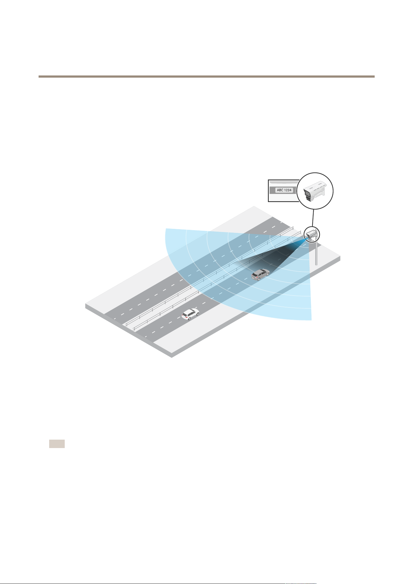
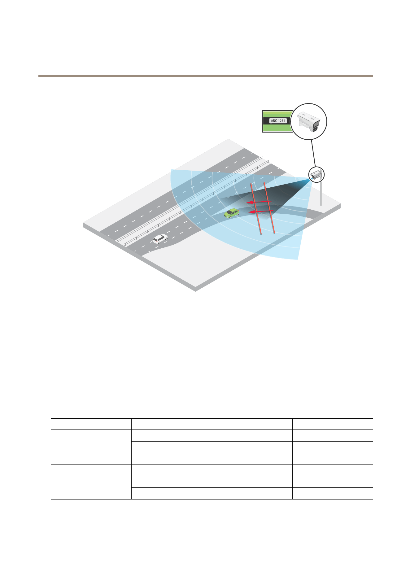
A radar - video fusion camera is a visual camera with a fully integrated radar module. As such, this camera can use the radar to
measure the speed of approaching or departing vehicles, and the video to capture license plates.
Use AXIS Q1686 - DLE with an optional license plate capture application, like AXIS License Plate V erier , or with a third - party
solution, to process the images and speed provided by the camera.
AXIS Q1686 - DLE is mounted on a pole on the side of a highway , and measures the speed and cap-
tures the license plates of approaching vehicles.
Radar - video fusion
Each technology in AXIS Q1686 - DLE – radar , video, and optional license plate capture software – generates metadata on its own. The
metadata includes information like speed, object class, direction, and license plate information. What’s special about this device is
that it fuses the metadata, which means it connects the speed and license plate of the same vehicle.
Note
AXIS Q1686 - DLE produces the fused metadata, which needs to be processed by a video management software (VMS) or other
platform. The VMS requests the metadata through the RTSP metadata stream and can use the data to trigger actions or
log statistics.
The fused metadata is not available in the web interface of the device.
3
AXIS Q1686 - DLE Radar - Video Fusion Camera
Installation
Installation
This video shows an example of how to install a radar - video fusion camera.
For complete instructions on all installation scenarios as well as important safety information, see the installation guide on
axis.com/products/axis - q1686 - dle/support
T o watch this video, go to the web version of this document.
help.axis.com/?&piaId=95369§ion=solution - overview
Note: The optical unit of the camera in the video is not identical with the one in AXIS Q1686 - DLE.
Preview mode
Preview mode is ideal for installers when ne tuning the camera view during the installation. No login is required to access the
camera view in preview mode. It is available only in factory defaulted state for a limited time from powering up the device.
T o watch this video, go to the web version of this document.
help.axis.com/?&piaId=95369§ion=preview - mode
This video demonstrates how to use preview mode.
Considerations
Where to install the product
Mount the product appropriately to get the best video and radar coverage. Consider the following when you mount a radar - video
fusion camera that is going to be used for license plate capture:
Center or side mounted
Y ou can mount the camera on a gantry above the road, or on a sturdy pole on the side of a road. The ability to capture license plates
and measure the speed of vehicles is affected by factors like the mounting height of the device, its position, the zoom of the camera,
and the speed of approaching or departing vehicles. For more information about possible mounting scenarios, see .
Environment
Environmental aspects can affect the performance of the video and the radar . Direct sunlight can distort the image and affect the
camera’s ability to capture license plates. Solid and metal objects, such as road signs, trees or large bushes, can affect the radar by
4

AXIS Q1686 - DLE Radar - Video Fusion Camera
Installation
creating blind spots (radar shadow) behind the object. Metal objects in the eld of detection, such as containers or trams, can cause
reections that affect the radar’s ability to perform classications, which can lead to ghost tracks and false alarms in the radar stream.
1
Actual detection
2
Reected detection (ghost track)
Radar coexistence
If you mount more than eight radars or radar - video fusion cameras operating on the 60 GHz frequency band close together , they may
interfere with each other , which can affect the radar’s performance.
License plate capture software
AXIS Q1686 - DLE doesn’t include any license plate capture software. However , the device is built on an open platform, which makes it
possible to use the device with third - party solutions on the edge or server side.
Y ou can use AXIS Q1686 - DLE with the edge application AXIS License Plate V erier . The combination has been thoroughly tested
and produces metadata that connects the speed and direction of a vehicle with its license plate. For recommendations on how to
mount the device when you’re going to use it with AXIS License Plate V erier , see .
For information about third - party options for license plate capture, see axis.com/support/tools/technology - partner - nder . Contact
your preferred supplier for recommendations on how to use the software.
Radar coverage
The radar in AXIS Q1686 - DLE has a horizontal eld of detection of 95°. Its detection range depends on factors like the mounting
height and tilt angle of the device, and the size and speed of moving vehicles. The detection range also depends on the radar prole.
There are two available proles in this radar: road monitoring and area monitoring . The road monitoring prole is optimized for
tracking vehicles moving at speeds up to 200 km/h (125 mph) while the area monitoring prole is optimized for tracking humans,
vehicles and unknown objects moving at speeds up to 55 km/h (34 mph).
By default, the radar prole in AXIS Q1686 - DLE is set to Road monitoring . For more information about the radar’s detection range
when used for road monitoring, see .
If you want to use AXIS Q1686 - DLE for area monitoring instead, select the Area monitoring prole. For information about the
radar’s detection range when used for area monitoring, see .
Note
T o change the radar prole, go to Radar > Settings > Detection .
Road detection range
The road monitoring prole in the radar is optimized for detection of vehicles and is recommended when you use the radar - video
fusion camera for speed measurement and license plate capture. With the road monitoring prole, the radar provides a speed
accuracy of +/ - 2 km/h (1.25 mph) when monitoring approaching or departing vehicles moving at up to 200 km/h (125 mph).
The mounting height of the radar - video fusion camera and the vehicle speed impacts the detection range of the radar . When
mounted at an optimal installation height, the radar detects approaching and departing vehicles within the following ranges:
• 25–1 00 m (82–328 ft) for vehicles moving at 50 km/h (3 1 mph).
• 40–80 m (13 1–262 ft) for vehicles moving at 1 00 km/h (62 mph).
5
AXIS Q1686 - DLE Radar - Video Fusion Camera
Installation
• 50–7 0 m (164–230 ft) for vehicles moving at 200 km/h (125 mph).
Note
T o minimize the risk of missed detections of vehicles travelling in high speeds, set up a scenario in the radar that triggers on
the object types V ehicle and Unknown . For more information about how to set up a radar scenario, see .
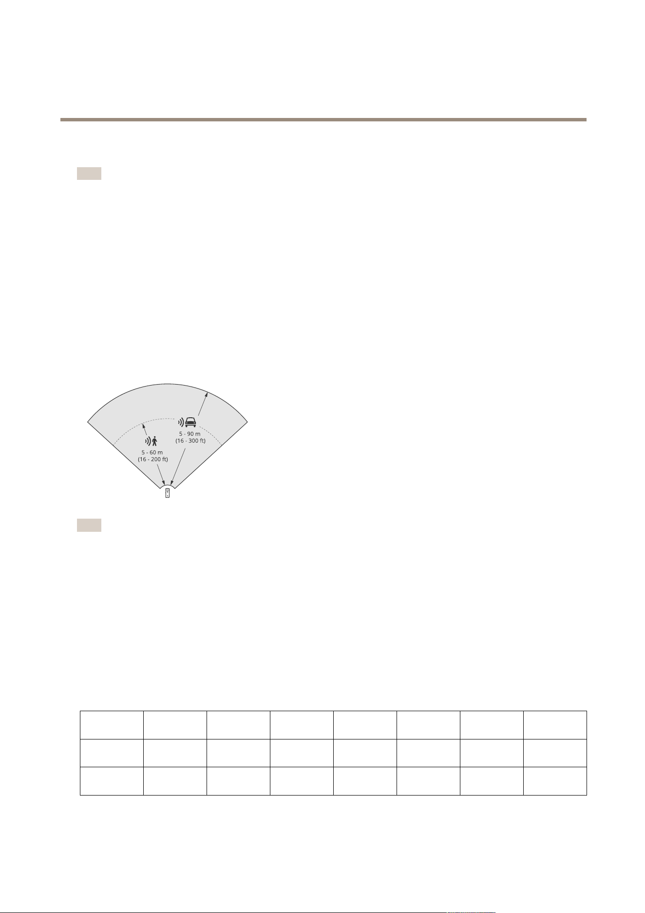
Area detection range
The detection range is the distance within which an object can be tracked and can trigger an alarm. It’s measured from a near
detection limit (how close to the device a detection can be made) to a far detection limit (how far from the device a detection
can be made).
The area monitoring prole is optimized for human detection, however , it will also allow you to track vehicles and other objects
moving at up to 55 km/h (34 mph) with a speed accuracy of +/ - 2 km/h (1.25 mph).
When mounted at the optimal installation height, the detection ranges are:
• 5 – 60 m (16–200 ft) when detecting a human
• 5 – 90 m (16–300 ft) when detecting a vehicle
Note
• Enter the mounting height in the web interface when you calibrate the radar .
• The detection range is affected by the scene and the product’s tilt angle.
• The detection range is affected by the moving object type and size.
The radar detection range was measured under these conditions:
• The range was measured along the ground.
• The object was a person with a height of 17 0 cm (5 ft 7 in).
• The person was walking straight in front of the radar .
• The values were measured when the person entered the detection zone.
• The radar sensitivity was set to Medium .
Mounting
height
15° tilt 20° tilt 25° tilt 30° tilt 35° tilt 40° tilt 45° tilt
3.5 m
(1 1 ft)
6.0–60+ m
(19–196+ ft)
5.0–60+ m
(16–196+ ft)
4.0–60+ m
(13–196+ ft)
4.0–60 m
(13–196 ft)
4.0–55 m
(13– 180 ft)
4.0–40 m
(13–13 1 ft)
4.0–30 m
(13–98 ft)
4.5 m
(14 ft)
6.0–60+ m
(19–196+ ft)
6.0–60+ m
(19–196+ ft)
5.0–60+ m
(16–196+ ft)
4.0–60+ m
(13–96+ ft)
4.0–60 m
(13–196 ft)
4.0–45 m
(13–147 ft)
4.0–40 m
(13–13 1 ft)
6
AXIS Q1686 - DLE Radar - Video Fusion Camera
Installation
Mounting
height
15° tilt 20° tilt 25° tilt 30° tilt 35° tilt 40° tilt 45° tilt
6 m
(19 ft)
1 0–60+ m
(32–196+ ft)
9.0–60+ m
(29–196+ ft)
7.0–60+ m
(22–196+ ft)
6.0–60+ m
(19–196+ ft)
6.0–60 m
(19–196 ft)
5.0–55 m
(16–180 ft)
5.0–55 m
(16–180 ft)
8 m
(26 ft)
16–60 m
(52–196 ft)
14–60 m
(45–196 ft)
1 0–60 m
(32–196 ft)
8.0–60+ m
(26–196+ ft)
8.0–60+ m
(26–196+ ft)
7.0–60 m
(22–196 ft)
7.0–60 m
(22–196 ft)
1 0 m
(32 ft)
2 1–60 m
(68–196 ft)
19–60 m
(62–196 ft)
14–60 m
(45–196 ft)
12–60+ m
(39–196+ ft)
1 0–60+ m
(32–196+ ft)
9.0–60 m
(29–196 ft)
9.0–60 m
(29–196 ft)
12 m
(39 ft)
25–60 m
(82–196 ft)
23–60 m
(75–196 ft)
19–60 m
(62–196 ft)
16–60+ m
(52–196+ ft)
13–60+ m
(42–196+ ft)
1 1–60 m
(36–196 ft)
1 1–55 m
(36–180 ft)
Note
• Setting the radar sensitivity to Low will decrease the detection range by 20% while setting it to High will increase the
detection range by 20%.
• In installations where you expect small animals to appear outside the fusion zone, but still in the detection zone of the radar ,
you can minimize the false alarms by setting the radar sensitivity to Low . This will however reduce the detection range.
Installation examples and use cases
Installation examples
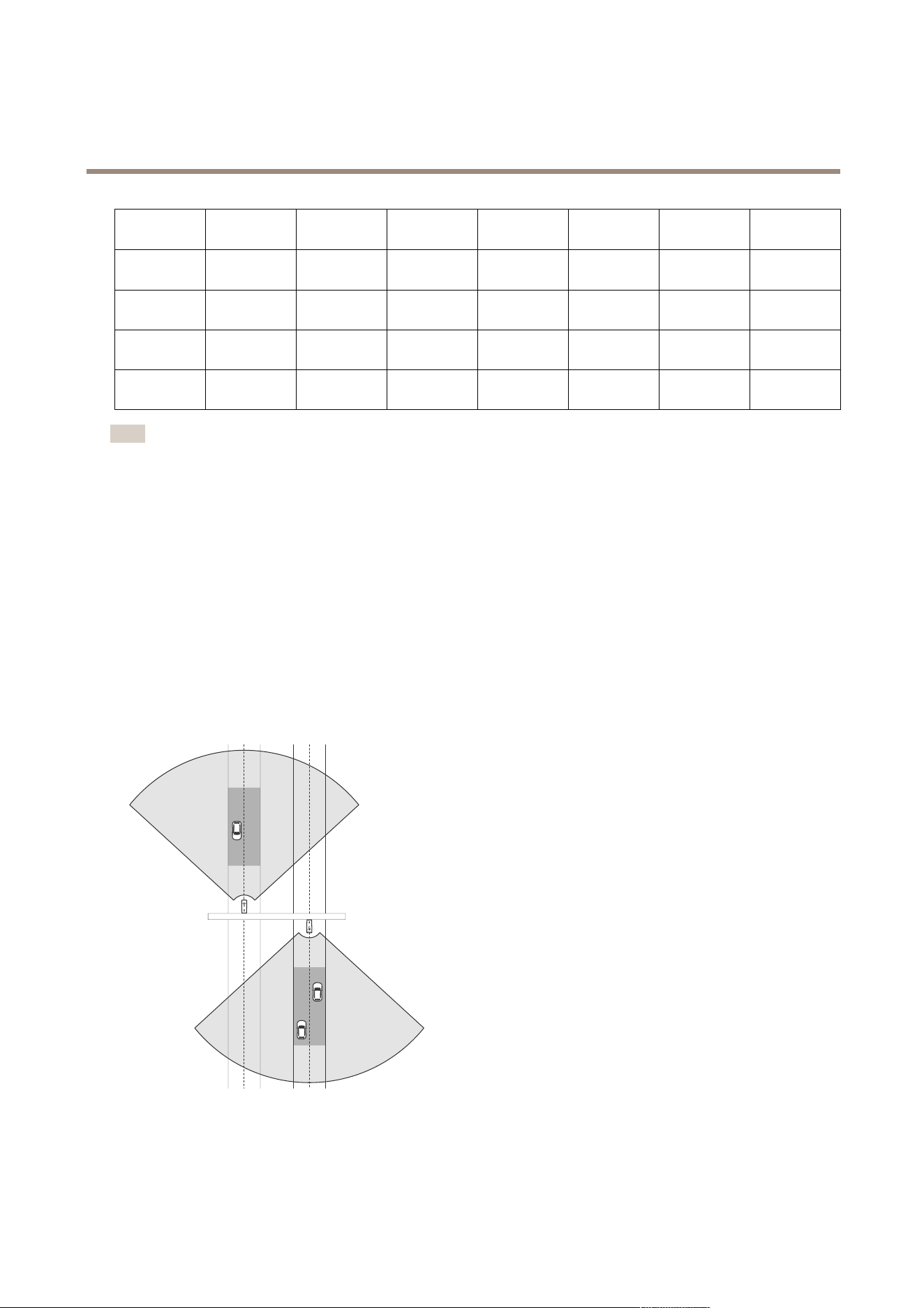
Center mounted
Y ou can mount the radar - video fusion camera on a gantry above the road. This is the recommended placement if you want to
measure the speed and capture license plates in two adjacent lanes.
Place the camera above the vehicles to view the license plates head on, and make sure to zoom in so that the lane, or lanes,
where you intend to capture license plates cover the image.
The same type of installation is possible if you want to capture license plates and the speed of vehicles that drive away from
the radar - video fusion camera, instead of driving towards it.
7
AXIS Q1686 - DLE Radar - Video Fusion Camera
Installation
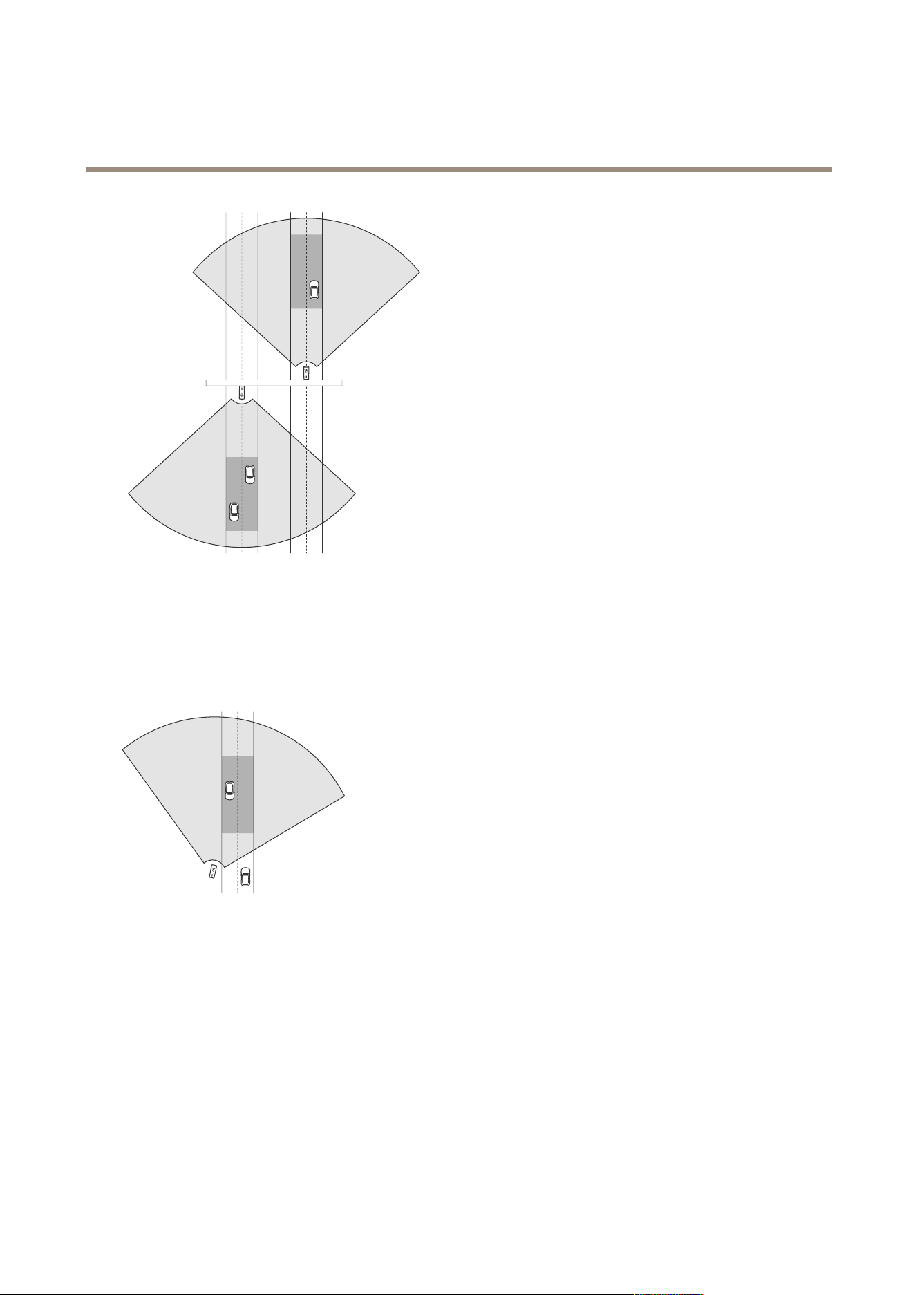
Side mounted
Y ou can mount the radar - video fusion camera on a sturdy pole on the side of the road. If you intend to capture license plates in
two lanes in this type of installation, we recommend a lateral distance of max 7 m (23 ft) between the camera and the centre of
the farthest lane on the road.
Make sure to zoom in so that the lane, or lanes, where you intend to capture license plates cover the image.
Recommendations
• For recommendations about how to mount the device when using AXIS License Plate V erier , see .
• For information about license plate capture in general, see the white paper “License plate capture” at
axis.com/learning/white - papers .
Road monitoring use cases
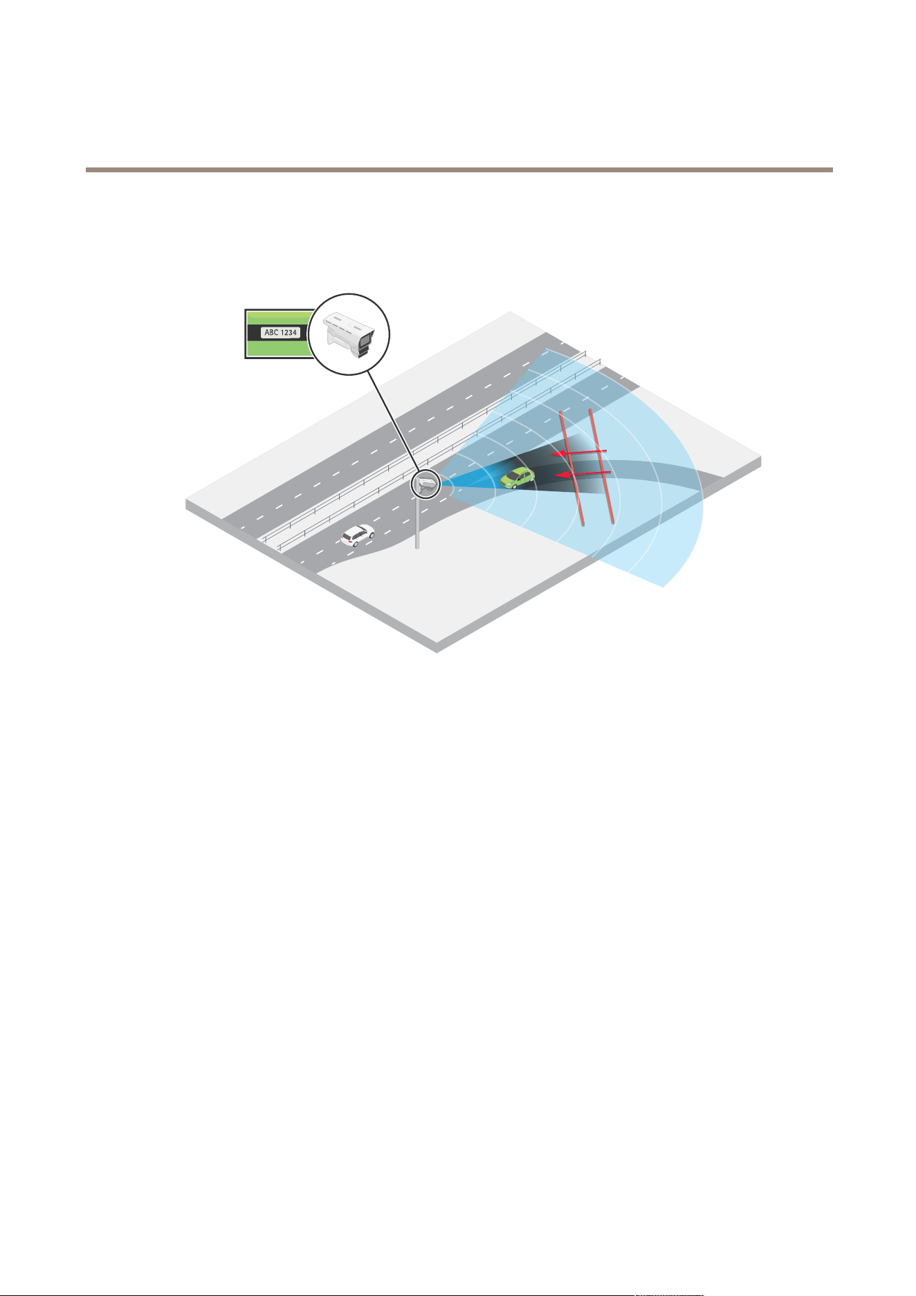
Wrong - way detection
T o capture the speed and license plates of vehicles driving in the wrong direction on a highway ramp, trafc control uses
AXIS Q1686 - DLE with AXIS License Plate V erier installed.
8
AXIS Q1686 - DLE Radar - Video Fusion Camera
Installation
They mount the camera on a pole facing the ramp according to . For reliable detections, they set up a line crossing scenario in the
radar pages of the device’s web interface and congure it so that a vehicle must cross two virtual lines to trigger an alarm. In the
radar scenario, they position the two lines across the ramp and specify the driving direction and speed the radar should trigger on.
With this conguration, the radar detects vehicles and their speed when driving in the wrong direction. At the same time, the camera
can provide visual identication and capture the license plates of the vehicles. With this setup it’s possible to create rules for events,
for example to trigger a recording when the vehicle crosses the lines, or trigger external lights that can warn the driver . Additionally ,
the license plate information can be processed on the server side.
The same setup is possible for capturing rear license plates. The radar measures the speed of departing vehicles while the camera
captures the rear license plates.
9
AXIS Q1686 - DLE Radar - Video Fusion Camera
Installation
For an example of how to create a rule that triggers a recording, see .
Mounting recommendations
AXIS Q1686 - DLE has been thoroughly tested with the application AXIS License Plate V erier . The mounting recommendations in the
following tables are based on the combined performance of the camera, radar and application.
The optimal distance for the device to capture license plates of vehicles travelling in high speeds is 40 m (13 1 ft). As seen in the
tables, you can capture license plates closer or further away than 40 m (13 1 ft), but at slower speeds.
Center mounted
This table shows the recommendations for a device that is mounted on a gantry above the road where there is no lateral distance
between the camera and the road.
Mounting height Tilt angle
Capture distance Speed
13°
25 m (82 ft) Up to 80 km/h (50 mph)
9°
40 m (13 1 ft) Up to 200 km/h (124 mph)
6 m (19.7 ft)
7°
50 m (164 ft) Up to 125 km/h (78 mph)
18°
25 m (82 ft) Up to 80 km/h (50 mph)
1 1°
40 m (13 1 ft) Up to 160 km/h (99 mph)
8 m (26.2 ft)
9°
50 m (164 ft) Up to 1 04 km/h (65 mph)
Denitions of the table parameters are available in .
1 0

AXIS Q1686 - DLE Radar - Video Fusion Camera
Installation
Side mounted
This table shows the recommendations for a device that is mounted on a pole on the side of the road where the lateral distance
from the camera to the centre of the farthest lane on the road is max 7 m (23 ft).
Mounting height Tilt angle P an angle
Capture distance Speed
13° 16°
25 m (82 ft) Up to 50 km/h (3 1 mph)
9° 1 0°
40 m (13 1 ft) Up to 140 km/h (87
mph)
6 m (19.7 ft)
7° 8°
50 m (164 ft) Up to 125 km/h (78
mph)
18° 16°
25 m (82 ft) Up to 50 km/h (3 1 mph)
1 1° 1 0°
40 m (13 1 ft) Up to 140 km/h (87
mph)
8 m (26.2 ft)
9° 8°
50 m (164 ft) Up to 1 04 km/h (65
mph)
Denitions of the table parameters are available in .
For information about how to congure the device so it can measure the speed of passing vehicles and capture license plates, see .
Denitions
• Mounting height : The distance from the ground up to the optics in the device.
• Tilt angle : The downward tilt angle, or vertical angle, of the device.
• P an angle : The horizontal angle of the device when it’s side mounted and directed at the point on the road where you
expect to capture license plates.
• Capture distance : The distance from the device to the point on the road where you expect to capture license plates
• Speed : The maximum speed at which the device can capture license plates and at the same time measure the speed
of passing vehicles.
1 1

AXIS Q1686 - DLE Radar - Video Fusion Camera
Get started
Get started
Find the device on the network
T o nd Axis devices on the network and assign them IP addresses in Windows®, use AXIS IP Utility or AXIS Device Manager . Both
applications are free and can be downloaded from axis.com/support .
For more information about how to nd and assign IP addresses, go to How to assign an IP address and access your device .
Browser support
Y ou can use the device with the following browsers:
Chrome
T M
Firefox
®
Edge
T M
Safari
®
Windows
®
recommended
recommended
macOS
®
recommended recommended
Linux
®
recommended recommended
Other operating systems *
*T o use AXIS OS web interface with iOS 15 or iP adOS 15, go to Settings Settings
Settings
> >
>
Safari Safari
Safari
> >
>
Advanced Advanced
Advanced
> >
>
Experimental Experimental
Experimental
Features Features
Features
and disable
NSURLSession W ebsocket.
Open the device's web interface
1. Open a browser and type the IP address or host name of the Axis device.
If you do not know the IP address, use AXIS IP Utility or AXIS Device Manager to nd the device on the network.
2. T ype the username and password. If you access the device for the rst time, you must create an administrator account. See .
For descriptions of all the controls and options in the device’s web interface, see .
Create an administrator account
The rst time you log in to your device, you must create an administrator account.
1. Enter a username.
2. Enter a password. See .
3. Re - enter the password.
4. Accept the license agreement.
5. Click Add account .
Important
The device has no default account. If you lose the password for your administrator account, you must reset the device. See .
Secure passwords
Important
Axis devices send the initially set password in clear text over the network. T o protect your device after the rst login, set
up a secure and encrypted HTTPS connection and then change the password.
12
AXIS Q1686 - DLE Radar - Video Fusion Camera
Get started
The device password is the primary protection for your data and services. Axis devices do not impose a password policy as they
may be used in various types of installations.
T o protect your data we strongly recommend that you:
• Use a password with at least 8 characters, preferably created by a password generator .
• Don’t expose the password.
• Change the password at a recurring interval, at least once a year .
V erify that no one has tampered with the device software
T o make sure that the device has its original AXIS OS, or to take full control of the device after a security attack:
1. Reset to factory default settings. See .
After the reset, secure boot guarantees the state of the device.
2. Congure and install the device.
W eb interface overview
This video gives you an overview of the device’s web interface.
T o watch this video, go to the web version of this document.
help.axis.com/?&piaId=95369§ion=web - interface - overview
Axis device web interface
13

AXIS Q1686 - DLE Radar - Video Fusion Camera
Configur e your device
Configur e your device
Optimize the device for speed measurement and license plate capture
This radar - video fusion camera is factory - calibrated so that the camera and radar module are perfectly aligned.
Note
Do not move or remove the lens, optical unit or radar module since this will undo the calibration and alignment.
T o set up the device for vehicle detection and speed measurement, and to optimize the image for license plate capture, follow
these steps:
1.
2.
3.
4.
5.
6.
7.
Set the mounting height in the radar
The mounting height is measured from the ground up to the optics in the device and should be as accurate as possible to detect
and measure the speed of passing vehicles correctly . For scenes with uneven surfaces, add the value that represents the average
height in the scene.
1. Go to Radar > Settings > General .
2. Set the height under Mounting height .
Aim and tilt the device
Aim and tilt the device towards the area where you intend to capture license plates.
Note
This procedure requires physical access to the device.
1. If you’re using the device with AXIS License Plate V erier , check the tables in for tilt angle recommendations based on
mounting height of the device, intended capture distance, and vehicle speed.
If you’re using a third - party license plate capture solution, contact your supplier for recommendations.
2. Loosen the screw in the wall mount.
3. Aim the camera at the road where you intend to capture license plates.
4. Tilt the device according to the recommendations.
5. V alidate the position of the device, see for instructions.
V alidate the mounting height and tilt
Note
This procedure requires physical access to the device.
14

AXIS Q1686 - DLE Radar - Video Fusion Camera
Configur e your device
T o validate the position of the device, add an augmented overlays in the camera’s live view . The overlay shows a projection of the
radar through a grid, including the distance from the device to the road. This will help you check that the radar detects vehicles
correctly at the intended capture distance.
1. Go to Video > Image .
2. Click in the live view to access the device’s onscreen controls.
3. Expand Predened controls .
4. T urn on Augmented overlay (radar) .
5. Click T oggle augmented overlay .
6. In the camera’s live view , check that the distance to the road is correct in the projected grid.
7. If necessary , re - measure the mounting height and adjust the settings, or adjust the tilt angle, and check again.
8. When you have validated the position of the device, tighten the screws in the wall mount.
Note
T urn off the augmented overlay when you’re done with the validation.
Add lanes in the radar
Add lanes in the radar that correspond to the lanes on the road you are monitoring. The lanes in the radar improves the tracking and
performance when detecting vehicles and the speed they’re travelling in.
1. Go to Radar > Settings > Object Visualization .
2. Set T rail lifetime to 1 hour .
This shows the trail of passing vehicles on the road, which makes it easier to position the lanes.
3. Go to Radar > Lanes .
4. Click + Add lane .
5. By default, the name of the rst lane will be Lane 1 . Expand it to edit the name.
6. Click on the lane in the radar view and use the mouse to move and shape it to cover the desired part of the radar view or
reference map. One lane in the radar should correspond to one lane on the road you are monitoring.
7. Check that the trail of the passing vehicles stays within the lane, or lanes, you have added.
8. Click Lanes enabled to activate the lanes you have added.
Repeat the steps to add an additional lane. W e recommend that you add a maximum of two lanes.
Example:
15
AXIS Q1686 - DLE Radar - Video Fusion Camera
Configur e your device
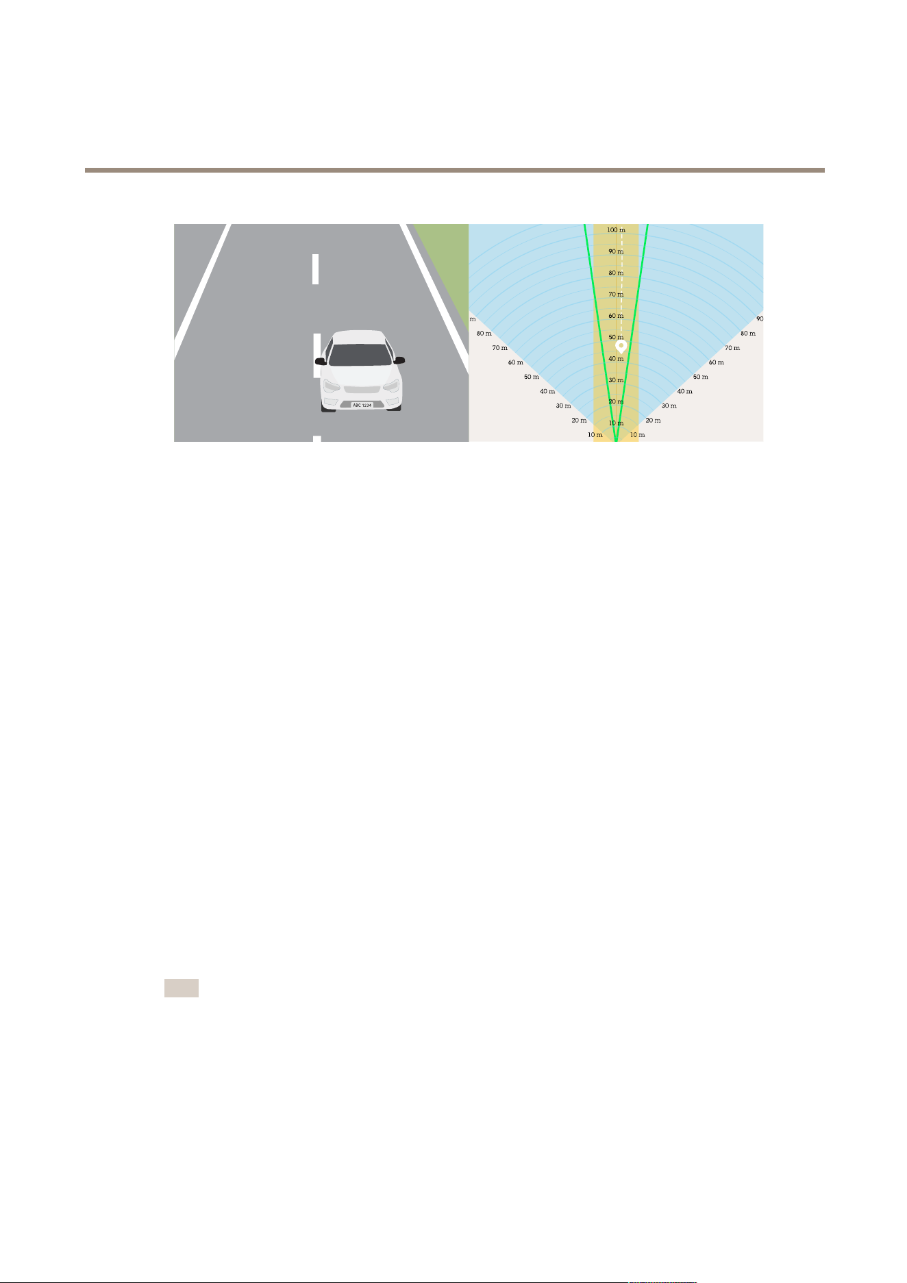
The camera view is illustrated on the left side, and the radar view with two added lanes in yellow on the right. The passing car is
shown as a white track in the radar view , followed by a trail.
T o change the unit of measurement in the radar grid, go to System > Regional settings .
Add exclude zones
Exclude zones are areas in which moving objects will be ignored. Add exclude zones to ignore, for example, swaying foliage on the side
of a road. Y ou could also add exclude zones to ignore ghost tracks caused by radar - reective materials, for example a metal fence.
Add an exclude zone:
1. Go to Radar > Exclude zones .
2. Click Add exclude zone .
Use the mouse to move and shape the zone so that it covers the desired part of the radar view or reference map.
Optimize the image for license plate capture
1. In the device’s web interface, go to Video > Installation > T rafc camera installation assistant .
2. Select the surveillance mode License plate capture .
3. Click Next .
4. Under Capture settings , add the following information:
- Camera height : the distance between the camera and the ground.
- Road distance : the lateral distance between the camera and the middle of the lane that you are going to monitor .
- T ypical car speed : the typical speed of the approaching or departing vehicles.
Note
T urn on Accelerometer to calculate the car distance automatically .
- Car distance : the distance between the camera and the approaching or departing vehicles.
5. Click Next in the trafc camera installation assistant.
6. The assistant provides a scene prole and a max shutter value for your installation. T o save these settings, click Apply
settings .
7. In the live view , zoom in so that the view covers the lane or lanes that you want to monitor . See for more information.
16

AXIS Q1686 - DLE Radar - Video Fusion Camera
Configur e your device
8. T o verify the settings, record a few vehicles passing by and look at the license plates in the recording. See for more
information.
Set up a license plate capture solution
Set up a license plate capture solution that can process the images provided by the camera. For more information, see .
AXIS License Plate V erier
If you’re going to use AXIS Q1686 - DLE with AXIS License Plate V erier , see AXIS License Plate V erier user manual for information
about how to set up the application.
If you intend to capture license plates in two lanes, we recommend that you create one area of interest for each lane in the
application. For instructions, see Adjust the area of interest in AXIS License Plate V erier user manual.
T o validate that AXIS License Plate V erier captures the license plates correctly , turn on license plate overlays in the web interface
of AXIS Q1686 - DLE. For more information, see .
Basic settings
Set the capture mode
1. Go to Video > Installation > Capture mode .
2. Click Change .
3. Select a capture mode and click Save and restart .
See also .
Set the power line frequency
1. Go to Video > Installation > P ower line frequency .
2. Click Change .
3. Select a power line frequency and click Save and restart .
Adjust the image
This section includes instructions about conguring your device. If you want to learn more about how certain features work, go to .
Level the camera
T o adjust the view in relation to a reference area or an object, use the level grid in combination with a mechanical adjustment
of the camera.
1. Go to Video > Image > and click .
2. Click to show the level grid.
3. Adjust the camera mechanically until the position of the reference area or the object is aligned with the level grid.
Adjust the zoom and focus
T o adjust the zoom:
1. Go to Video > Installation and adjust the zoom slider .
17

AXIS Q1686 - DLE Radar - Video Fusion Camera
Configur e your device
T o adjust the focus:
1. Click to show the autofocus area.
2. Adjust the autofocus area to cover the part of the image that you want to be in focus.
If you don’t select an autofocus area, the camera focuses on the entire scene. For trafc scenes where you intend to
capture license plates, we recommend that you focus on the lines in the centre of the road.
3. Click Autofocus .
4. T o ne tune the focus, adjust the focus slider .
Select scene prole
A scene prole is a set of predened image appearance settings including color level, brightness, sharpness, contrast and local
contrast. Scene proles are precongured in the product for quick setup to a specic scenario, for example Forensic which is
optimized for surveillance conditions. For a description of each available setting, see .
Y ou can select a scene prole during the initial setup of the camera. Y ou can also select or change scene prole later .
1. Go to Video > Image > Appearance .
2. Go to Scene prole and select a prole.
Reduce image processing time with low latency mode
Y ou can optimize the image processing time of your live stream by turning on low latency mode. The latency in your live stream is
reduced to a minimum. When you use low latency mode, the image quality is lower than usual.
1. Go to System > Plain cong .
2. Select ImageSource from the drop - down list.
3. Go to ImageSource/I0/Sensor > Low latency mode and select On .
4. Click Save .
Select exposure mode
T o improve image quality for specic surveillance scenes, use exposure modes. Exposure modes lets you control aperture, shutter
speed, and gain. Go to Video > Image > Exposure and select between the following exposure modes:
• For most use cases, select Automatic exposure.
• For environments with certain articial lighting, for example uorescent lighting, select Flicker - free .
Select the same frequency as the power line frequency .
• For environments with certain articial light and bright light, for example outdoors with uorescent lighting at night and
sun during daytime, select Flicker - reduced .
Select the same frequency as the power line frequency .
• T o lock the current exposure settings, select Hold current .
Benet from IR light in low - light conditions by using night mode
Y our camera uses visible light to deliver color images during the day . But as the visible light diminishes, color images become less
bright and clear . If you switch to night mode when this happens, the camera uses both visible and near - infrared light to deliver bright
and detailed black - and - white images instead. Y ou can set the camera to switch to night mode automatically .
18

AXIS Q1686 - DLE Radar - Video Fusion Camera
Configur e your device
1. Go to Video > Image > Day - night mode , and make sure that the IR - cut lter is set to Auto .
2. T o use the built - in IR light when the camera is in night mode, turn on Allow illumination and Synchronize illumination .
Optimize IR illumination
Depending on the installation environment and the conditions around the camera, for example external light sources in the scene,
you can sometimes improve the image quality if you manually adjust the intensity of the LEDs. If you have problems with reections
from the LEDs, you can try to reduce the intensity .
1. Go to Video > Image > Day - night mode .
2. T urn on Allow illumination .
3. Click in the live view and select Manual .
4. Adjust the intensity .
Reduce noise in low - light conditions
T o reduce noise in low - light conditions, you can adjust one or more of the following settings:
• Adjust the trade - off between noise and motion blur . Go to Video > Image > Exposure and move the Blur - noise trade - off
slider toward Low noise .
• Set the exposure mode to automatic.
Note
A high max shutter value can result in motion blur .
• T o slow down the shutter speed, set max shutter to the highest possible value.
Note
When you reduce the max gain, the image can become darker .
• Set the max gain to a lower value.
• If possible, move the slider under Aperture toward Open .
• Reduce sharpness in the image, under Video > Image > Appearance .
Reduce motion blur in low - light conditions
T o reduce motion blur in low - light conditions, adjust one or more of the following settings in Video > Image > Exposure :
• Move the Blur - noise trade - off slider toward Low motion blur .
Note
When you increase the gain, image noise also increases.
• Set Max shutter to a shorter time, and Max gain to a higher value.
If you still have problems with motion blur:
• Increase the light level in the scene.
• Mount the camera so that objects move toward it or away from it rather than sideways.
19

AXIS Q1686 - DLE Radar - Video Fusion Camera
Configur e your device
Maximize the details in an image
Important
If you maximize the details in an image, the bitrate will probably increase and you might get a reduced frame rate.
• Make sure to select the capture mode that has the highest resolution.
• Go to Video > Stream > General and set the compression as low as possible.
• Below the live view image, click and in Video format , select MJPEG .
• Go to Video > Stream > Zipstream and select Off .
Handle scenes with strong backlight
Dynamic range is the difference in light levels in an image. In some cases the difference between the darkest and the brightest
areas can be signicant. The result is often an image where either the dark or the bright areas are visible. Wide dynamic range
(WDR) makes both dark and bright areas of the image visible.
1. Go to Video > Image > Wide dynamic range .
2. Use the Local contrast slider to adjust the amount of WDR.
3. Use the T one mapping slider to adjust the amount of WDR.
4. If you still have problems, go to Exposure and adjust the Exposure zone to cover the area of interest.
Find out more about WDR and how to use it at axis.com/web - articles/wdr .
Stabilize a shaky image with image stabilization
Image stabilization is suitable in environments where the product is mounted in an exposed location where vibrations can occur , for
example, due to wind or passing trafc.
The feature makes the image smoother , steadier , and less blurry . It also reduces the le size of the compressed image and lowers the
bitrate of the video stream.
Note
When you turn on image stabilization, the image is slightly cropped, which lowers the maximum resolution.
1. Go to Video > Installation > Image correction .
2. T urn on Image stabilization .
Hide parts of the image with privacy masks
Y ou can create one or several privacy masks to hide parts of the image.
1. Go to Video > Privacy masks .
2. Click .
3. Click the new mask and type a name.
4. Adjust the size and placement of the privacy mask according to your needs.
5. T o change the color for all privacy masks, click Privacy masks and select a color .
See also
20

AXIS Q1686 - DLE Radar - Video Fusion Camera
Configur e your device
Show an image overlay
Y ou can add an image as an overlay in the video stream.
1. Go to Video > Overlays .
2. Select Image and click .
3. Click Images .
4. Drag and drop an image.
5. Click Upload .
6. Click Manage overlay .
7. Select the image and a position. Y ou can also drag the overlay image in the live view to change the position.
Show a text overlay
Y ou can add a text eld as an overlay in the video stream. This is useful for example when you want to display the date, time or a
company name in the video stream.
1. Go to Video > Overlays .
2. Select T ext and click .
3. T ype the text you want to display in the video stream.
4. Select a position. Y ou can also drag the overlay text eld in the live view to change the position.
Add street names and compass direction to the image
Note
The street name and compass direction will be visible on all video streams and recordings.
1. Go to Apps .
2. Select axis - orientationaid .
3. Click Open .
4. T o add a street name, click Add text and modify the text to t the street.
5. T o add a compass, click Add compass and modify the compass to t the image.
Show license plate overlays
License plate overlays are available with the optional application AXIS License Plate V erier .
1. Go to Video > Image .
2. Click in the live view to access the device’s onscreen controls.
3. Expand Predened controls .
4. T urn on License plate overlay .
5. Click Show overlay .
2 1

AXIS Q1686 - DLE Radar - Video Fusion Camera
Configur e your device
6. T o move the overlay , click Move overlay .
View and record video
This section includes instructions about conguring your device. T o learn more about how streaming and storage works, go to .
Reduce bandwidth and storage
Important
Reducing the bandwidth can lead to loss of detail in the image.
1. Go to Video > Stream .
2. Click in the live view .
3. Select Video format H.264 .
4. Go to Video > Stream > General and increase Compression .
5. Go to Video > Stream > Zipstream and do one or more of the following:
Note
The Zipstream settings are used for both H.264 and H.265.
- Select the Zipstream Strength that you want to use.
- T urn on Optimize for storage . This can only be used if the video management software supports B - frames.
- T urn on Dynamic FPS .
- T urn on Dynamic GOP and set a high Upper limit GOP length value.
Note
Most web browsers don’t support H.265 decoding and because of this the device doesn’t support it in its web interface.
Instead you can use a video management system or application that supports H.265 decoding.
Set up network storage
T o store recordings on the network, you need to set up your network storage.
1. Go to System > Storage .
2. Click Add network storage under Network storage .
3. T ype the IP address of the host server .
4. T ype the name of the shared location on the host server under Network share .
5. T ype the username and password.
6. Select the SMB version or leave it on Auto .
7. Select Add share without testing if you experience temporary connection issues, or if the share is not yet congured.
8. Click Add .
22

AXIS Q1686 - DLE Radar - Video Fusion Camera
Configur e your device
Record and watch video
Record video directly from the camera
1. Go to Video > Image .
2. T o start a recording, click .
If you haven’t set up any storage, click and . For instructions on how to set up network storage, see
3. T o stop recording, click again.
W atch video
1. Go to Recordings .
2. Click for your recording in the list.
V erify that no one has tampered with the video
With signed video, you can make sure that no one has tampered with the video recorded by the camera.
1. Go to Video > Stream > General and turn on Signed video .
2. Use AXIS Camera Station (5.46 or later) or another compatible video management software to record video. For
instructions, see the AXIS Camera Station user manual .
3. Export the recorded video.
4. Use AXIS File Player to play the video. Download AXIS File Player .
indicates that no one has tampered with the video.
Note
T o get more information about the video, right - click the video and select Show digital signature .
Additional radar settings
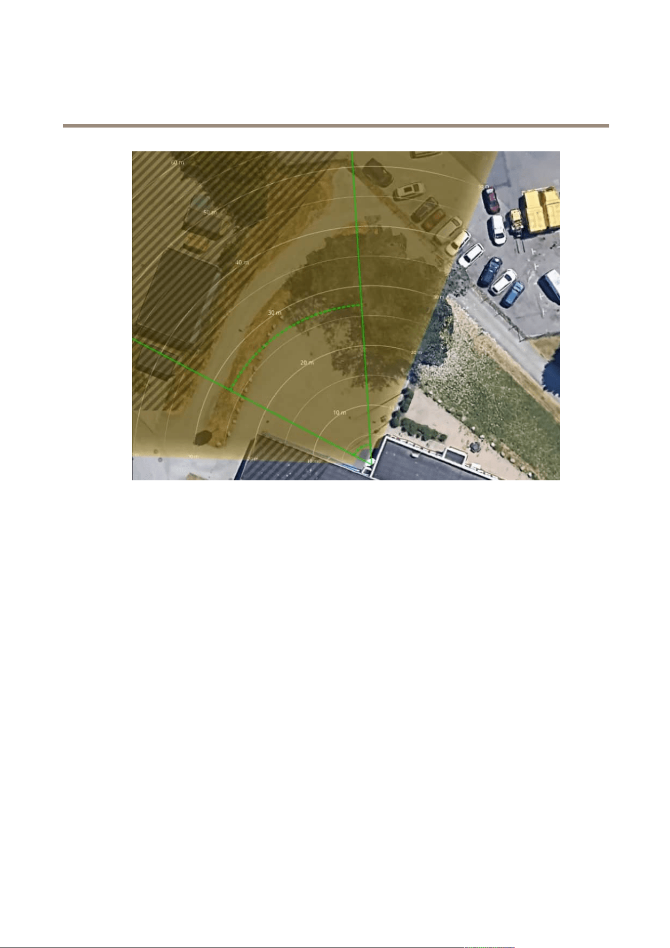
Upload a reference map
The default live view of the radar will show the radar coverage and any detected movement, and you can add detection zones and
rules right away . T o make it easier to see where objects are moving, upload a reference map, for example a ground plan or an aerial
photo, that shows the area covered by the radar .
23
AXIS Q1686 - DLE Radar - Video Fusion Camera
Configur e your device
Image requirements:
• Supported le formats are jpeg and png.
• The orientation is not important, since the radar coverage shape will move to adapt to the image during calibration.
Upload the reference map and calibrate it so that the actual radar coverage ts the position, direction and scale of the map.
1. Go to Radar > Map calibration .
2. Upload your reference map and follow the setup assistant.
Add scenarios
A scenario is a combination of triggering conditions and detection settings, which you can use to create rules in the event system.
Add scenarios if you want to create different rules for different parts of the scene.
Add a scenario:
1. Go to Radar > Scenarios .
2. Click Add scenario .
3. T ype the name of the scenario.
4. Select if you want to trigger on objects moving in an area or on objects crossing one, or two, lines.
T rigger on objects moving in an area:
1. Select Movement in area .
2. Click Next .
24

AXIS Q1686 - DLE Radar - Video Fusion Camera
Configur e your device
3. Select the type of zone that should be included in the scenario.
Use the mouse to move and shape the zone so that it covers the desired part of the radar image or reference map.
4. Click Next .
5. Add detection settings.
5.1 Add seconds until trigger after under Ignore short - lived objects .
5.2 Select which object type to trigger on under T rigger on object type .
5.3 Add a range for the speed limit under Speed limit .
6. Click Next .
7. Set the minimum duration of the alarm under Minimum trigger duration .
8. Click Save .
T rigger on objects crossing a line:
1. Select Line crossing .
2. Click Next .
3. P osition the line in the scene.
Use the mouse to move and shape the line.
4. T o change the detection direction, turn on Change direction .
5. Click Next .
6. Add detection settings.
6.1 Add seconds until trigger after under Ignore short - lived objects .
6.2 Select which object type to trigger on under T rigger on object type .
6.3 Add a range for the speed limit under Speed limit .
7. Click Next .
8. Set the minimum duration of the alarm under Minimum trigger duration .
The default value is set to 2 seconds. If you want the scenario to trigger every time an object crosses the line, lower
the duration to 0 seconds.
9. Click Save .
T rigger on objects crossing two lines:
1. Select Line crossing .
2. Click Next .
3. T o make the object cross two lines for the alarm to trigger , turn on Require crossing of two lines .
4. P osition the lines in the scene.
Use the mouse to move and shape the line.
5. T o change the detection direction, turn on Change direction .
6. Click Next .
25

AXIS Q1686 - DLE Radar - Video Fusion Camera
Configur e your device
7. Add detection settings.
7.1 Set the time limit between crossing the rst and the second line under Max time between crossings .
7.2 Select which object type to trigger on under T rigger on object type .
7.3 Add a range for the speed limit under Speed limit .
8. Click Next .
9. Set the minimum duration of the alarm under Minimum trigger duration .
The default value is set to 2 seconds. If you want the scenario to trigger every time an object has crossed the two lines,
lower the duration to 0 seconds.
1 0. Click Save .
Show a text overlay with the tilt angle of the radar
Y ou can add an overlay in the radar’s live view that shows the tilt angle of the radar . This is helpful during installation, or whenever
you need to know the tilt angle of the device.
Note
The tilt angle overlay shows “90” when the device is horizontal. If the overlay shows “75”, the tilt angle of the radar
is 15° below the horizon.
1. Go to Radar > Overlays .
2. Select T ext and click .
3. T ype #op .
Y ou can also click Modier and select #op from the list.
4. Select a position. Y ou can also drag the overlay eld in the live view to change the position.
Set up rules for events
T o learn more, check out our guide Get started with rules for events .
T rigger an action
1. Go to System > Events and add a rule. The rule denes when the device will perform certain actions. Y ou can set
up rules as scheduled, recurring, or manually triggered.
2. Enter a Name .
3. Select the Condition that must be met to trigger the action. If you specify more than one condition for the rule, all of the
conditions must be met to trigger the action.
4. Select which Action the device should perform when the conditions are met.
Note
If you make changes to an active rule, the rule must be turned on again for the changes to take effect.
Note
If you change the denition of a stream prole that is used in a rule, then you need to restart all the rules that use that
stream prole.
26

AXIS Q1686 - DLE Radar - Video Fusion Camera
Configur e your device
Save power when no motion is detected
This example explains how to turn on power saving mode when no motion is detected in the scene.
Note
When you turn on power saving mode, the IR illumination range is reduced.
Make sure that AXIS Object Analytics is running:
1. Go to Apps > AXIS Object Analytics .
2. Start the application if it is not already running.
3. Make sure you have set up the application according to your needs.
Create a rule:
1. Go to System > Events and add a rule.
2. T ype a name for the rule.
3. In the list of conditions, under Application , select Object Analytics .
4. Select Invert this condition .
5. In the list of actions, under P ower saving mode , select Use power saving mode while the rule is active .
6. Click Save .
Record video when the camera detects an object
This example explains how to set up the camera to start recording to the SD card when the camera detects an object. The recording
will include ve seconds before detection and one minute after detection ends.
Before you start:
• Make sure you have an SD card installed.
Make sure that AXIS Object Analytics is running:
1. Go to Apps > AXIS Object Analytics .
2. Start the application if it is not already running.
3. Make sure you have set up the application according to your needs.
Create a rule:
1. Go to System > Events and add a rule.
2. T ype a name for the rule.
3. In the list of conditions, under Application , select Object Analytics .
4. In the list of actions, under Recordings , select Record video while the rule is active .
5. In the list of storage options, select SD_DISK .
6. Select a camera and a stream prole.
7. Set the prebuffer time to 5 seconds.
8. Set the postbuffer time to 1 minute.
9. Click Save .
27

AXIS Q1686 - DLE Radar - Video Fusion Camera
Configur e your device
Show a text overlay in the video stream when the device detects an object
This example explains how to display the text “Motion detected” when the device detects an object.
Make sure that AXIS Object Analytics is running:
1. Go to Apps > AXIS Object Analytics .
2. Start the application if it is not already running.
3. Make sure you have set up the application according to your needs.
Add the overlay text:
1. Go to Video > Overlays .
2. Under Overlays , select T ext and click .
3. Enter #D in the text eld.
4. Choose text size and appearance.
5. T o position the text overlay , click and select an option.
Create a rule:
1. Go to System > Events and add a rule.
2. T ype a name for the rule.
3. In the list of conditions, under Application , select Object Analytics .
4. In the list of actions, under Overlay text , select Use overlay text .
5. Select a video channel.
6. In T ext , type “Motion detected”.
7. Set the duration.
8. Click Save .
Note
If you update the overlay text it will be automatically updated on all video streams dynamically .
Provide visual indication of an ongoing event
Y ou have the option to connect the AXIS I/O Indication LED to your network camera. This LED can be congured to turn on whenever
certain events occur in the camera. For example, to let people know that video recording is in progress.
Required hardware
• AXIS I/O Indication LED
• An Axis network video camera
Note
For instructions on how to connect the AXIS I/O Indication LED, see the installation guide provided with the product.
The following example shows how to congure a rule that turns on the AXIS I/O Indication LED to indicate that camera is recording.
1. Go to System > Accessories > I/O ports .
28

AXIS Q1686 - DLE Radar - Video Fusion Camera
Configur e your device
2. For the port that you connected the AXIS I/O Indication LED to, click to set the direction to Output , and click
to set the normal state to Circuit open .
3. Go to System > Events .
4. Create a new rule.
5. Select the Condition that must be met to trigger the camera to start recording. It can, for example, be a time schedule or
motion detection.
6. In the list of actions, select Record video . Select a storage space. Select a stream prole or create a new . Also set the
Prebuffer and P ostbuffer as required.
7. Save the rule.
8. Create a second rule and select the same Condition as in the rst rule.
9. In the list of actions, select T oggle I/O while the rule is active , and then select the port the AXIS I/O Indication LED is
connected to. Set the state to Active .
1 0. Save the rule.
Other scenarios where AXIS I/O Indication LED can be used are for example:
• Congure the LED to turn on when the camera starts, to indicate the presence of the camera. Select System ready as
a condition.
• Congure the LED to turn on when live stream is active to indicate that a person or a program is accessing a stream from
the camera. Select Live stream accessed as a condition.
Record video when the camera detects impact
Shock detection allows the camera to detect tampering caused by vibrations or shock. Vibrations due to the environment or to an
object can trigger an action depending on the shock sensitivity range, which can be set from 0 to 1 00. In this scenario, someone is
throwing rocks at the camera after hours and you would like to get a video clip of the event.
T urn on shock detection:
1. Go to System > Detectors > Shock detection .
2. T urn on shock detection, and adjust the shock sensitivity .
Create a rule:
3. Go to System > Events > Rules and add a rule.
4. T ype a name for the rule.
5. In the list of conditions, under Device status , select Shock detected .
6. Click + to add a second condition.
7. In the list of conditions, under Scheduled and recurring , select Schedule .
8. In the list of schedules, select After hours .
9. In the list of actions, under Recordings , select Record video while the rule is active .
1 0. Select where to save the recordings.
1 1. Select a Camera .
12. Set the prebuffer time to 5 seconds.
29

AXIS Q1686 - DLE Radar - Video Fusion Camera
Configur e your device
13. Set the postbuffer time to 50 seconds.
14. Click Save .
T rigger an alarm if someone opens the housing
This example explains how to trigger an alarm if someone opens the housing.
Add a recipient:
1. Go to System > Events > Recipients and click Add recipient .
2. T ype a name for the recipient.
3. Select Email .
4. T ype an email address to send the email to.
5. The camera doesn’t have it’s own email server , so it will need to log into another email server to be able to send mails. Fill
in the rest of the information according to your email provider .
6. T o send a test email, click T est .
7. Click Save .
Create a rule:
8. Go to System > Events > Rules and add a rule.
9. T ype a name for the rule.
1 0. In the list of conditions, select Casing open .
1 1. In the list of actions, select Send notication to email .
12. Select a recipient from the list.
13. T ype a subject and a message for the email.
14. Click Save .
Send an email automatically if someone spray paints the lens
Activate the tampering detection:
1. Go to System > Detectors > Camera tampering .
2. Set a value for T rigger delay . The value indicates the time that must pass before an email is sent.
3. T urn on T rigger on dark images to detect if the lens is sprayed, covered, or rendered severely out of focus.
Add an email recipient:
4. Go to System > Events > Recipients and add a recipient.
5. T ype a name for the recipient.
6. Select Email .
7. T ype an email address to send the email to.
8. The camera doesn’t have it’s own email server , so it has to log into another email server to send mails. Fill in the rest of the
information according to your email provider .
9. T o send a test email, click T est .
30

AXIS Q1686 - DLE Radar - Video Fusion Camera
Configur e your device
1 0. Click Save .
Create a rule:
1 1. Go to System > Events > Rules and add a rule.
12. T ype a name for the rule.
13. In the list of conditions, under Video , select T ampering .
14. In the list of actions, under Notications , select Send notication to email and then select the recipient from the list.
15. T ype a subject and a message for the email.
16. Click Save .
Use MQTT to send radar data
Use the radar - video fusion camera with the application AXIS Speed Monitor to collect radar data for detected objects and send
it over MQTT .
This example explains how to set up an MQTT client in the device where you have installed AXIS Speed Monitor , and how to create a
condition that will publish the radar data collected in AXIS Speed Monitor as a payload to an MQTT broker .
Before you start:
• Install AXIS Speed Monitor in your radar - video fusion camera, or install it in a camera that you connect to the radar
in the radar - video fusion camera.
For more information, see AXIS Speed Monitor user manual .
• Set up an MQTT broker and get the broker’s IP address, username and password.
Learn more about MQTT and MQTT brokers in AXIS OS Knowledge Base .
Set up the MQTT client in the web interface of the device where you have installed AXIS Speed Monitor:
1. Go to System > MQTT > MQTT client > Broker and enter the following information:
- Host : The broker IP address
- Client ID : The ID of the device
- Protocol : The protocol the broker is set to
- P ort : The port number used by the broker
- The broker Username and P assword
2. Click Save and Connect .
Create a condition that publishes the radar data as a payload to the MQTT broker:
3. Go to System > MQTT > MQTT publication and click + Add condition .
4. In the list of conditions, under Application , select Speed Monitor: T rack exited zone .
The device will now be able to send information about the radar tracks for every moving object that exits a scenario. Every object will
have its own radar track parameters, for example rmd_zone_name , tracking_id , and trigger_count . Y ou can nd the full list of
parameters in AXIS Speed Monitor user manual .
T rigger a recording if a vehicle drives in the wrong direction
This example explains how to trigger a recording and record video to an SD card if the radar detects that a vehicle drives in the
wrong direction.
3 1

AXIS Q1686 - DLE Radar - Video Fusion Camera
Configur e your device
Before you start:
• Make sure you have installed an SD card.
Add a scenario in the radar :
1. Go to Radar > Scenarios .
2. Click + Add scenario .
3. T ype the name of the scenario.
4. Select Line crossing .
5. Click Next .
6. T o make the object cross two lines for the alarm to trigger , turn on Require crossing of two lines .
7. P osition the lines in the scene.
Use the mouse to move and shape them.
8. T o change the detection direction, turn on Change direction .
9. Click Next .
1 0. Add detection settings.
1 0.1 Set the time limit between crossing the rst and the second line under Max time between crossings .
1 0.2 Select that you want to trigger on vehicles under T rigger on object type .
1 0.3 Add a range for the speed limit under Speed limit .
1 1. Click Next .
12. Set the minimum duration of the alarm under Minimum trigger duration .
The default value is set to 2 seconds. If you want the scenario to trigger every time an object has crossed the two lines,
lower the duration to 0 seconds.
13. Click Save .
Create a rule that triggers a recording :
1. Go to System > Events and add a rule
2. T ype a name for the rule.
3. In the list of conditions, under Radar motion , select the scenario you just created.
4. In the list of actions, under Recordings , select Record video while the rule is active .
5. In the list of storage options, select SD_DISK .
6. Select Camera 1 .
7. Set the prebuffer time to 5 seconds.
8. Set the postbuffer to 30 seconds.
9. Click Save .
32

AXIS Q1686 - DLE Radar - Video Fusion Camera
Configur e your device
Audio
Add audio to your recording
T urn on audio:
1. Go to Video > Stream > Audio and include audio.
2. If the device has more than one input source, select the correct one in Source .
3. Go to Audio > Device settings and turn on the correct input source.
4. If you make any changes to the input source, click Apply changes .
Edit the stream prole that is used for the recording:
5. Go to System > Stream proles and select the stream prole.
6. Select Include audio and turn it on.
7. Click Save .
Connect to a network speaker
Network speaker pairing allows you to use a compatible Axis network speaker as if it is connected directly to the camera. Once
paired, the speaker acts as an audio out device where you can play audio clips and transmit sound through the camera.
Important
For this feature to work with a video management software (VMS), you must rst pair the camera with the network speaker ,
then add the camera to your VMS.
P air camera with network speaker
1. Go to System > Edge - to - edge > P airing .
2. T ype the network speaker’s IP address, username and password.
3. Select Speaker pairing .
4. Click Connect . A conrmation message appears.
33
AXIS Q1686 - DLE Radar - Video Fusion Camera
The web inter face
The web inter face
T o reach the device’s web interface, type the device’s IP address in a web browser .
Note
Support for the features and settings described in this section varies between devices. This icon indicates that
the feature or setting is only available in some devices.
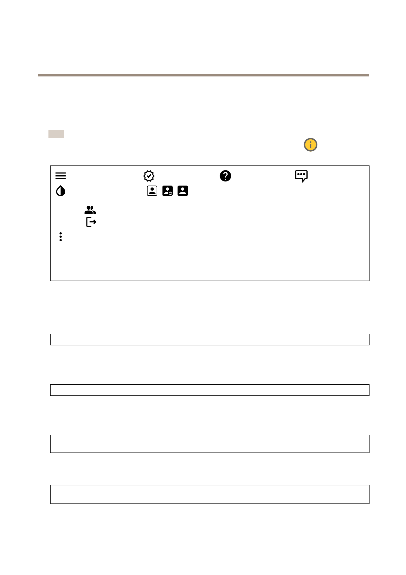
Show or hide the main menu. Access the release notes. Access the product help. Change the language.
Set light theme or dark theme. The user menu contains:
• Information about the user who is logged in.
• Change account : Log out from the current account and log in to a new account.
• Log out : Log out from the current account.
The context menu contains:
• Analytics data : Accept to share non - personal browser data.
• Feedback : Share any feedback to help us improve your user experience.
• Legal : View information about cookies and licenses.
• About : View device information, including AXIS OS version and serial number .
• Legacy device interface : Change the device’s web interface to the legacy version.
Status
Device info
Shows the device information, including AXIS OS version and serial number .
Upgrade AXIS OS : Upgrade the software on your device. T akes you to the Maintenance page where you can do the upgrade.
Time sync status
Shows NTP synchronization information, including if the device is in sync with an NTP server and the time remaining until
the next sync.
NTP settings : View and update the NTP settings. T akes you to the Date and time page where you can change the NTP settings.
Security
Shows what kind of access to the device that is active, what encryption protocols are in use, and if unsigned apps are allowed.
Recommendations to the settings are based on the AXIS OS Hardening Guide.
Hardening guide : Link to AXIS OS Hardening guide where you can learn more about cybersecurity on Axis devices and best
practices.
Connected clients
Shows the number of connections and connected clients.
View details : View and update the list of connected clients. The list shows IP address, protocol, port, state, and PID/process
of each connection.
34
AXIS Q1686 - DLE Radar - Video Fusion Camera
The web inter face
Ongoing recordings
Shows ongoing recordings and their designated storage space.
Recordings: View ongoing and ltered recordings and their source. For more information, see Shows the storage
space where the recording is saved.
Video
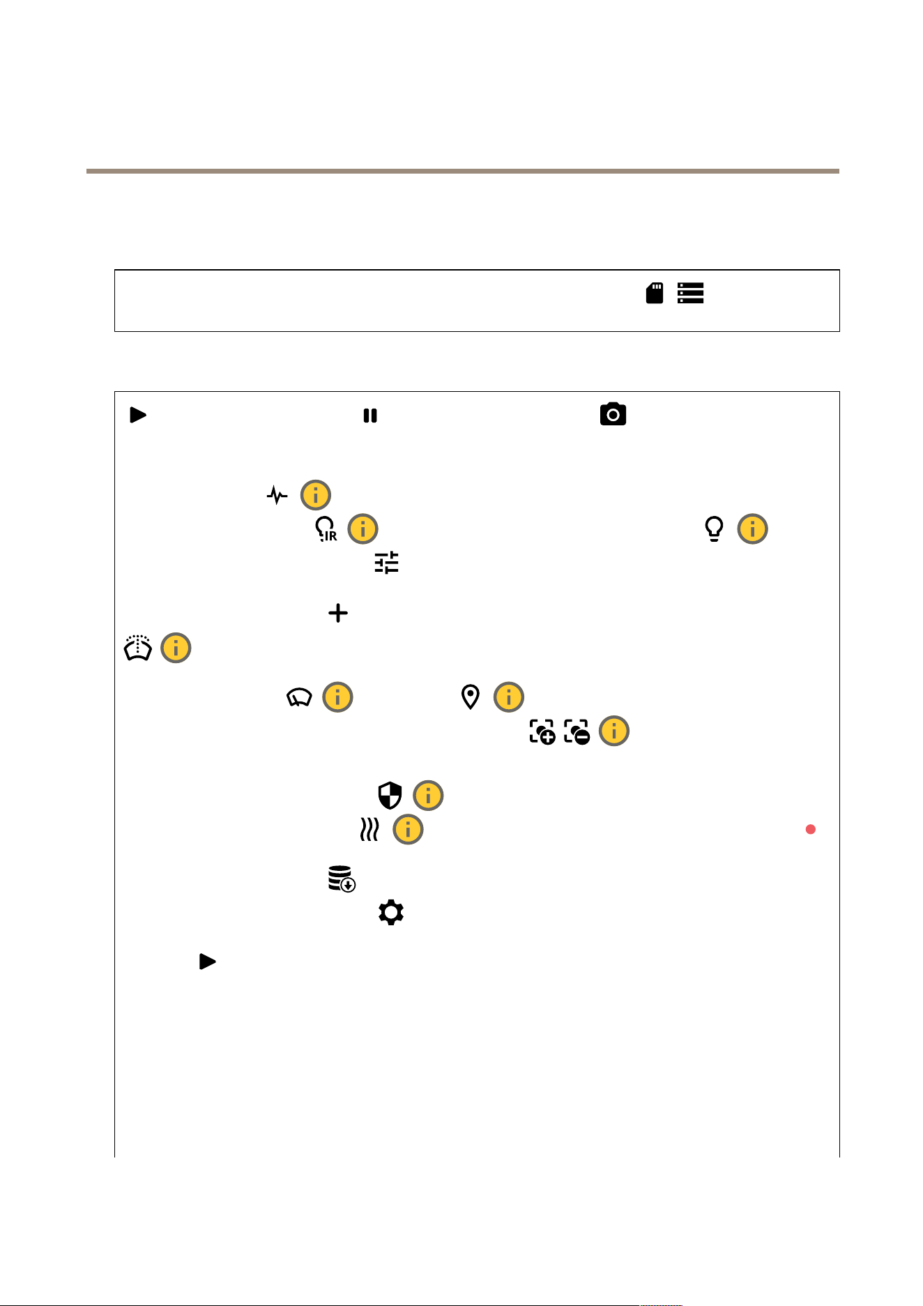
Click to play the live video stream. Click to freeze the live video stream. Click to take a snapshot
of the live video stream. The le is saved in the ‘Downloads’ folder on your computer . The image le name is
[snapshot_YYYY_MM_DD_HH_MM_SS.jpg]. The size of the snapshot depends on the compression that the specic web - browser
engine where the snapshot is received applies, therefore, the snapshot size may vary from the actual compression setting that is
congured in the device. Click to show I/O output ports. Use the switch to open or close the circuit of a port, for
example, to test external devices. Click to manually turn on or turn off the IR illumination. Click to
manually turn on or turn off the white light. Click to access onscreen controls:
• Predened controls : T urn on to use the available onscreen controls.
• Custom controls : Click Add custom control to add an onscreen control.
Starts the washer . When the sequence starts, the camera moves to the congured position to receive the wash spray .
When the whole wash sequence is completed, the camera returns to its previous position. This icon is only visible when the washer
is connected and congured. Starts the wiper . Click and select a preset position to go to that preset
position in the live view . Or , click Setup to go to the preset position page. Adds or removes a focus recall area.
When you add a focus recall area, the camera saves the focus settings at that specic pan/tilt range. When you have set a focus
recall area and the camera enters that area in the live view , the camera recalls the previously saved focus. It’s enough to cover half
of the area for the camera to recall the focus. Click to select a guard tour , then click Start to play the guard tour . Or ,
click Setup to go to the guard tours page. Click to manually turn on the heater for a selected period of time.
Click to start a continuous recording of the live video stream. Click again to stop the recording. If a recording is ongoing, it will
resume automatically after a reboot. Click to show the storage that is congured for the device. T o congure the storage,
you need to be logged in as an administrator . Click to access more settings:
• Video format : Select the encoding format to use in the live view .
• Autoplay : T urn on to autoplay a muted video stream whenever you open the device in a new session.
• Client stream information : T urn on to show dynamic information about the video stream used by the browser that
shows the live video stream. The bitrate information differs from the information shown in a text overlay , because of
different information sources. The bitrate in the client stream information is the bitrate of the last second, and it
comes from the encoding driver of the device. The bitrate in the overlay is the average bitrate of the last 5 seconds,
and it comes from the browser . Both values cover only the raw video stream and not the additional bandwidth
generated when it’s transported over the network through UDP/T CP/HTTP .
• Adaptive stream : T urn on to adapt the image resolution to the viewing client’s actual display resolution, to improve
the user experience and help prevent a possible overload of the client’s hardware. The adaptive stream is only
applied when you view the live video stream in the web interface in a browser . When adaptive stream is turned on,
the maximum frame rate is 30 fps. If you take a snapshot while adaptive stream is turned on, it will use the image
resolution selected by the adaptive stream.
35
AXIS Q1686 - DLE Radar - Video Fusion Camera
The web inter face
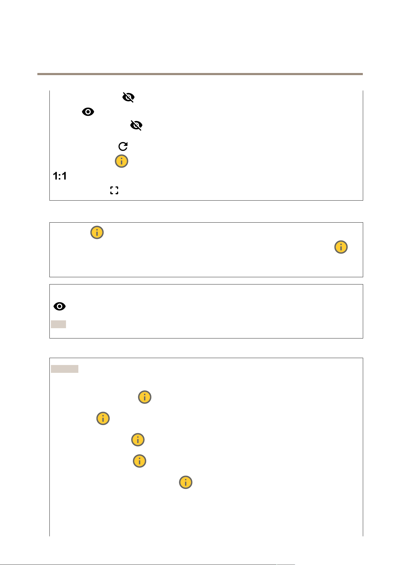
• Level grid : Click to show the level grid. The grid helps you decide if the image is horizontally aligned. Click
to hide it.
• Pixel counter : Click to show the pixel counter . Drag and resize the box to contain your area of interest. Y ou can
also dene the pixel size of the box in the Width and Height elds.
• Refresh : Click to refresh the still image in the live view .
• PTZ controls : T urn on to display PTZ controls in the live view .
Click to show the live view at full resolution. If the full resolution is larger than your screen size, use the smaller image to
navigate in the image. Click to show the live video stream in full screen. Press ESC to exit full screen mode.
Installation
Capture mode : A capture mode is a preset conguration that denes how the camera captures images. When you
change the capture mode, it can affect many other settings, such as view areas and privacy masks. Mounting position :
The orientation of the image can change depending on how you mount the camera. P ower line frequency : T o minimize image
icker , select the frequency your region uses. The American regions usually use 60 Hz. The rest of the world mostly uses 50 Hz. If
you're not sure of your region's power line frequency , check with the local authorities.
Zoom : Use the slider to adjust the zoom level. Focus : Use the slider to manually set the focus. AF : Click to make the camera focus
on the selected area. If you don’t select an autofocus area, the camera focuses on the entire scene. Autofocus area : Click
to show the autofocus area. This area should include the area of interest. Reset focus : Click to make the focus return to
its original position.
Note
In cold environments, it can take several minutes for the zoom and focus to become available.
Image correction
Important
W e recommend you not to use multiple image correction features at the same time, since it can lead to performance issues.
Barrel distortion correction (BDC) : T urn on to get a straighter image if it suffers from barrel distortion. Barrel distortion
is a lens effect that makes the image appear curved and bent outwards. The condition is seen more clearly when the image is
zoomed out. Crop : Use the slider to adjust the correction level. A lower level means that the image width is kept at the
expense of image height and resolution. A higher level means that image height and resolution are kept at the expense of
image width. Remove distortion : Use the slider to adjust the correction level. Pucker means that the image width is
kept at the expense of image height and resolution. Bloat means that image height and resolution are kept at the expense of
image width. Image stabilization : T urn on to get a smoother and steadier image with less blur . W e recommend that
you use image stabilization in environments where the device is mounted in an exposed location and subject to vibrations due
to, for example, wind or passing trafc. Focal length : Use the slider to adjust the focal length. A higher value leads to
higher magnication and a narrower angle of view , while a lower value leads to a lower magnication and a wider angle of
36
AXIS Q1686 - DLE Radar - Video Fusion Camera
The web inter face
view . Stabilizer margin : Use the slider to adjust the size of the stabilizer margin, which determines the level of vibration
to stabilize. If the product is mounted in an environment with a lot of vibration, move the slider towards Max . As a result, a
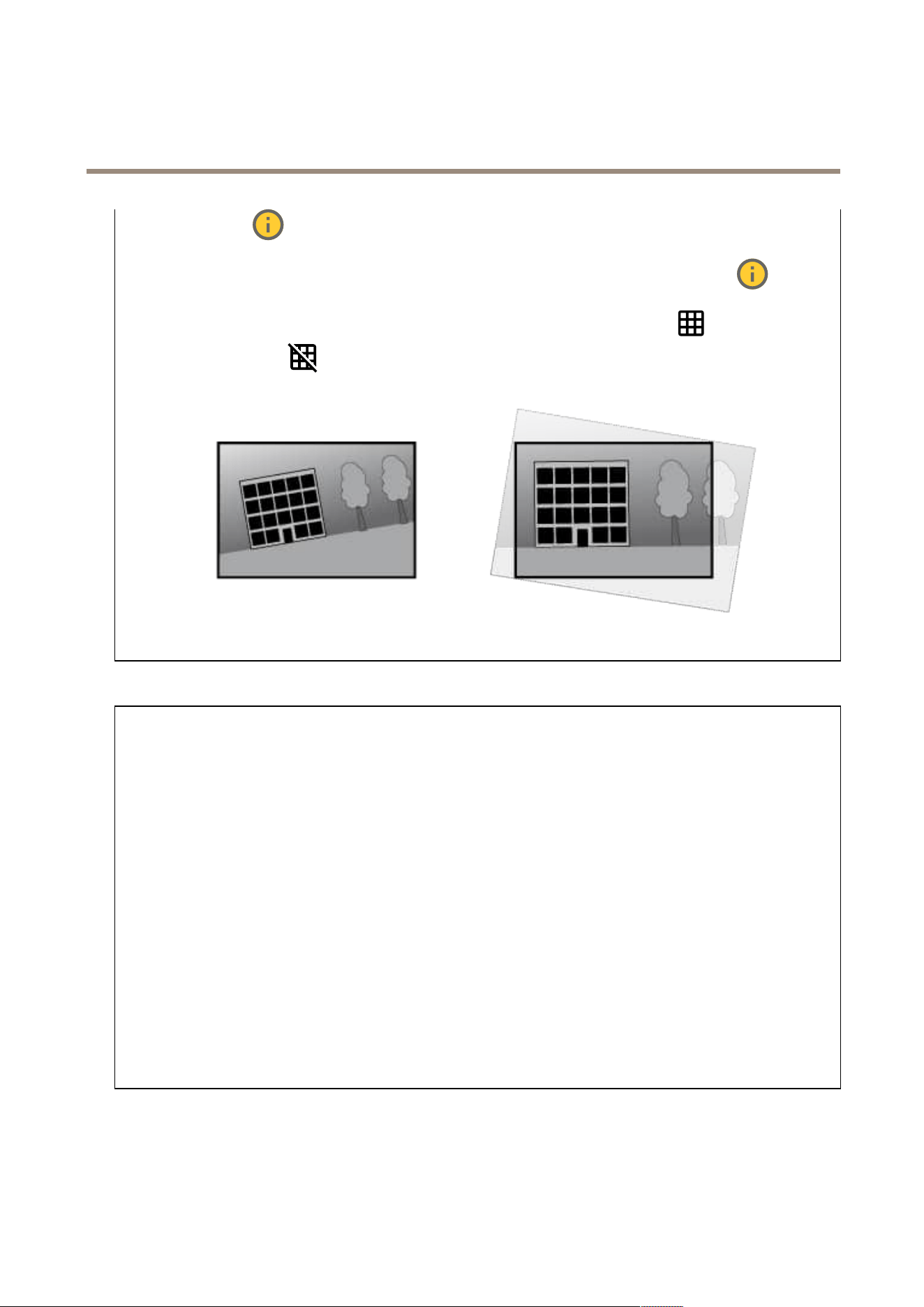
smaller scene is captured. If the environment has less vibration, move the slider towards Min . Straighten image : T urn on
and use the slider to straighten the image horizontally by rotating and cropping it digitally . The functionality is useful when
it’s not possible to mount the camera exactly level. Ideally , straighten the image during installation. : Click to show a
supporting grid in the image. : Click to hide the grid.
The image before and after it has been straightened.
T rafc camera installation assistance
Surveillance mode
• License plate capture : Select if you’re setting up the camera for license plate capture.
• T rafc overview : Select if you’re setting up the camera for road monitoring.
Capture settings
• Camera height : Enter the distance between the camera and the ground.
• Road distance : Enter the distance between the camera and the middle of the lane you are monitoring.
• T ypical car speed : Enter the typical car speed.
• Accelerometer : T urn on to automatically get the distance between the camera and the cars on the road.
• Car distance : Enter the distance between the camera and the cars on the road.
Installation overview
The overview shows the camera’s current position, and indicates if the position is according to recommendations. Red values
fall outside the recommendations.
• V ertical angle : The recommended vertical angle, or tilt angle, is between 0 and 29°.
• Horizontal angle : The recommended horizontal angle, or pan angle, is between 0 and 29°.
• Roll angle : The recommended roll angle is between 0 and 24°.
• Car distance : The calculated distance between the moving vehicles and the camera.
Image settings
An overview of the suggested Max shutter and Scene prole settings based on your conguration.
• Apply settings : Click to activate the conguration. Y our device reloads and updates the scene prole.
Image
Appearance
37
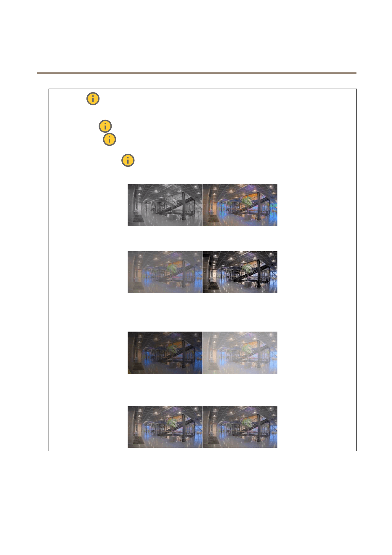
AXIS Q1686 - DLE Radar - Video Fusion Camera
The web inter face
Scene prole : Select a scene prole that suits your surveillance scenario. A scene prole optimizes image settings,
including color level, brightness, sharpness, contrast, and local contrast, for a specic environment or purpose.
• Forensic : Suitable for surveillance purposes.
• Indoor : Suitable for indoor environments.
• Outdoor : Suitable for outdoor environments.
• Vivid : Useful for demonstration purposes.
• T rafc overview : Suitable for vehicle trafc monitoring.
Saturation : Use the slider to adjust the color intensity . Y ou can, for example, get a grayscale image.
Contrast : Use the slider to adjust the difference between light and dark.
Brightness : Use the slider to adjust the light intensity . This can make objects easier to see. Brightness is applied after image
capture, and doesn’t affect the information in the image. T o get more details from a dark area, it’s usually better to increase
gain or exposure time.
Sharpness : Use the slider to make objects in the image appear sharper by adjusting the edge contrast. If you increase the
sharpness, it may increase the bitrate and the amount of storage space needed as well.
Wide dynamic range
38
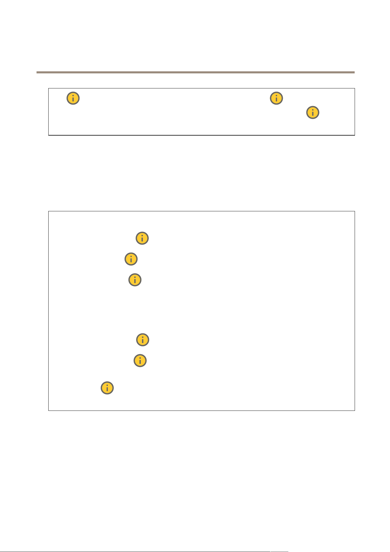
AXIS Q1686 - DLE Radar - Video Fusion Camera
The web inter face
WDR : T urn on to make both bright and dark areas of the image visible. Local contrast : Use the slider to adjust the
contrast of the image. A higher value makes the contrast higher between dark and light areas. T one mapping : Use the
slider to adjust the amount of tone mapping that is applied to the image. If the value is set to zero, only the standard gamma
correction is applied, while a higher value increases the visibility of the darkest and brightest parts in the image.
White balance
When the camera detects the color temperature of the incoming light, it can adjust the image to make the colors look more natural.
If this is not sufcient, you can select a suitable light source from the list.
The automatic white balance setting reduces the risk of color icker by adapting to changes gradually . If the lighting changes, or
when the camera is rst started, it can take up to 30 seconds to adapt to the new light source. If there is more than one type of light
source in a scene, that is, they differ in color temperature, the dominating light source acts as a reference for the automatic white
balance algorithm. This behavior can be overridden by choosing a xed white balance setting that matches the light source you
want to use as a reference.
Light environment :
• Automatic : Automatic identication and compensation for the light source color . This is the recommended setting
which can be used in most situations.
• Automatic – outdoors : Automatic identication and compensation for the light source color . This is the
recommended setting which can be used in most outdoor situations.
• Custom – indoors : Fixed color adjustment for a room with some articial light other than uorescent lighting
and good for a normal color temperature around 2800 K.
• Custom – outdoors : Fixed color adjustment for sunny weather conditions with a color temperature around
5500 K.
• Fixed – uorescent 1 : Fixed color adjustment for uorescent lighting with a color temperature around 4000 K.
• Fixed – uorescent 2 : Fixed color adjustment for uorescent lighting with a color temperature around 3000 K.
• Fixed – indoors : Fixed color adjustment for a room with some articial light other than uorescent lighting and
good for a normal color temperature around 2800 K.
• Fixed – outdoors 1 : Fixed color adjustment for sunny weather conditions with a color temperature around 5500 K.
• Fixed – outdoors 2 : Fixed color adjustment for cloudy weather condition with a color temperature around 6500 K.
• Street light – mercury : Fixed color adjustment for ultraviolet emission in mercury vapor lights common
in street lighting.
• Street light – sodium : Fixed color adjustment that compensates for the yellow orange color of sodium vapor
lights common in street lighting.
• Hold current : K eep the current settings and do not compensate for light changes.
• Manual : Fix the white balance with the help of a white object. Drag the circle to an object that you want
the camera to interpret as white in the live view image. Use the Red balance and Blue balance sliders to adjust the
white balance manually .
Day - night mode
39
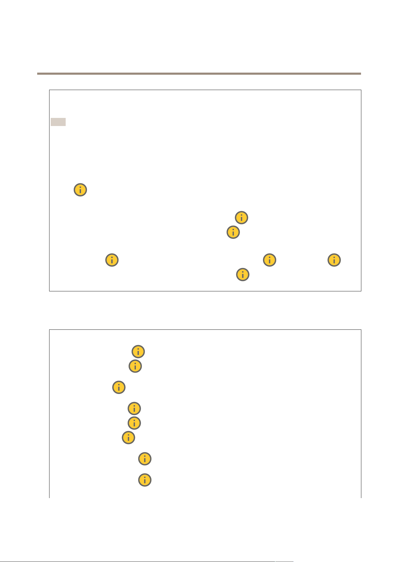
AXIS Q1686 - DLE Radar - Video Fusion Camera
The web inter face
IR - cut lter :
• Auto : Select to automatically turn on and off the IR - cut lter . When the camera is in day mode, the IR - cut lter
is turned on and blocks incoming infrared light, and when in night mode, the IR - cut lter is turned off and the
camera’s light sensitivity increases.
Note
• Some devices have IR - pass lters in night mode. The IR - pass lter increases IR - light sensitivity but blocks visible light.
• On : Select to turn on the IR - cut lter . The image is in color , but with reduced light sensitivity .
• Off : Select to turn off the IR - cut lter . The image is in black and white for increased light sensitivity .
Threshold : Use the slider to adjust the light threshold where the camera changes from day mode to night mode.
• Move the slider towards Bright to decrease the threshold for the IR - cut lter . The camera changes to night mode
earlier .
• Move the slider towards Dark to increase the threshold for the IR - cut lter . The camera changes to night mode later .
IR light If your device doesn’t have built - in illumination, these controls are only available when you connect a supporting
Axis accessory . Allow illumination : T urn on to let the camera use the built - in light in night mode. Synchronize illumination : T urn
on to automatically synchronize the illumination with the surrounding light. The synchronization between day and night only
works if the IR - cut lter is set to Auto or Off . Automatic illumination angle : T urn on to use the automatic illumination
angle. T urn off to set the illumination angle manually . Illumination angle : Use the slider to manually set the illumination
angle, for example, if the angle needs to be different from the camera’s angle of view . If the camera has a wide angle of view , you
can set the illumination angle to a narrower angle, which equals a greater tele position. This will result in dark corners in the
image. IR wavelength : Select the desired wavelength for the IR light. White light Allow illumination : T urn
on to let the camera use white light in night mode. Synchronize illumination : T urn on to automatically synchronize the
white light with the surrounding light.
Exposure
Select an exposure mode to reduce rapidly changing irregular effects in the image, for example, icker produced by different types of
light sources. W e recommend you to use the automatic exposure mode, or the same frequency as your power network.
Exposure mode :
• Automatic : The camera adjusts the aperture, gain, and shutter automatically .
• Automatic aperture : The camera adjusts the aperture and gain automatically . The shutter is xed.
• Automatic shutter : The camera adjusts the shutter and gain automatically . The aperture is xed.
• Hold current : Locks the current exposure settings.
• Flicker - free : The camera adjusts the aperture and gain automatically , and uses only the following shutter
speeds: 1/50 s ( 50 Hz) and 1/60 s ( 60 Hz).
• Flicker - free 50 Hz : The camera adjusts the aperture and gain automatically , and uses the shutter speed 1/50 s.
• Flicker - free 60 Hz : The camera adjusts the aperture and gain automatically , and uses the shutter speed 1/60 s.
• Flicker - reduced : This is the same as icker - free, but the camera might use shutter speeds faster than
1/1 00 s ( 50 Hz) and 1/120 s ( 60 Hz) for brighter scenes.
• Flicker - reduced 50 Hz : This is the same as icker - free, but the camera might use shutter speeds faster
than 1/1 00 s for brighter scenes.
• Flicker - reduced 60 Hz : This is the same as icker - free, but the camera might use shutter speeds faster
than 1/120 s for brighter scenes.
40
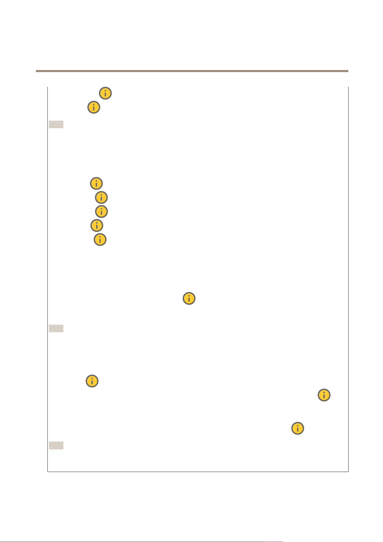
AXIS Q1686 - DLE Radar - Video Fusion Camera
The web inter face
• Manual : The aperture, gain, and shutter are xed.
Exposure zone : Use exposure zones to optimize the exposure in a selected part of the scene, for example, the area in
front of an entrance door .
Note
The exposure zones are related to the original image (unrotated), and the names of the zones apply to the original image.
This means, for example, that if the video stream is rotated 90°, then the Upper zone becomes the Right zone in the
stream, and Left becomes Lower .
• Automatic : Suitable for most situations.
• Center : Uses a xed area in the center of the image to calculate the exposure. The area has a xed size and
position in the live view .
• Full : Uses the entire live view to calculate the exposure.
• Upper : Uses an area with a xed size and position in the upper part of the image to calculate the exposure.
• Lower : Uses an area with a xed size and position in the lower part of the image to calculate the exposure.
• Left : Uses an area with a xed size and position in the left part of the image to calculate the exposure.
• Right : Uses an area with a xed size and position in the right part of the image to calculate the exposure.
• Spot : Uses an area with a xed size and position in the live view to calculate the exposure.
• Custom : Uses an area in the live view to calculate the exposure. Y ou can adjust the size and position of the area.
Max shutter : Select the shutter speed to provide the best image. Low shutter speeds (longer exposure) might cause motion blur
when there is movement, and a too high shutter speed might affect the image quality . Max shutter works with max gain to improve
the image. Max gain : Select the suitable max gain. If you increase the max gain, it improves the visible level of detail in dark
images, but also increases the noise level. More noise can also result in increased use of bandwidth and storage. If you set the max
gain to a high value, images can differ a lot if the light conditions are very different from day to night. Max gain works with max
shutter to improve the image. Motion - adaptive exposure : Select to reduce motion blur in low - light conditions. Blur - noise
trade - off : Use the slider to adjust the priority between motion blur and noise. If you want to prioritize low bandwidth and have
less noise at the expense of details in moving objects, move the slider towards Low noise . If you want to prioritize the preservation
of details in moving objects at the expense of noise and bandwidth, move the slider towards Low motion blur .
Note
Y ou can change the exposure either by adjusting the exposure time or by adjusting the gain. If you increase the exposure
time, it results in more motion blur , and if you increase the gain, it results in more noise. If you adjust the Blur - noise
trade - off towards Low noise , the automatic exposure will prioritize longer exposure times over increasing gain, and the
opposite if you adjust the trade - off towards Low motion blur . Both the gain and exposure time will eventually reach
their maximum values in low - light conditions, regardless of the priority set.
Lock aperture : T urn on to keep the aperture size set by the Aperture slider . T urn off to allow the camera to automatically
adjust the aperture size. Y ou can, for example, lock the aperture for scenes with permanent light conditions. Aperture : Use
the slider to adjust the aperture size, that is, how much light passes through the lens. T o allow more light to enter the sensor and
thereby produce a brighter image in low - light conditions, move the slider towards Open . An open aperture also reduces the depth
of eld, which means that objects close to or far from the camera can appear unfocused. T o allow more of the image to be in
focus, move the slider towards Closed . Exposure level : Use the slider to adjust the image exposure. Defog : T urn on to
detect the effects of foggy weather and automatically remove them for a clearer image.
Note
W e recommend you not to turn on Defog in scenes with low contrast, large light level variations, or when the autofocus is
slightly off. This can affect the image quality , for example, by increasing the contrast. Furthermore, too much light can
negatively impact the image quality when defog is active.
General
4 1
AXIS Q1686 - DLE Radar - Video Fusion Camera
The web inter face
Name : Enter a name for the selected camera.
Optics
T emperature compensation : T urn on if you want the focus position to be corrected based on the temperature in the
optics. IR compensation : T urn on if you want the focus position to be corrected when IR - cut lter is off and when there is
IR light. Calibrate zoom and focus : Click to reset the optics and the zoom and focus settings to the factory default position. Y ou
need to do this if the optics have lost calibration during transport, or if the device has been exposed to extreme vibrations.
Stream
General
Resolution : Select the image resolution suitable for the surveillance scene. A higher resolution increases bandwidth and
storage. Frame rate : T o avoid bandwidth problems on the network or reduce storage size, you can limit the frame rate to a xed
amount. If you leave the frame rate at zero, the frame rate is kept at the highest possible rate under the current conditions. A
higher frame rate requires more bandwidth and storage capacity . P - frames : A P - frame is a predicted image that shows only the
changes in the image from the previous frame. Enter the desired number of P - frames. The higher the number , the less bandwidth is
required. However , if there is network congestion, there could be a noticeable deterioration in the video quality . Compression : Use
the slider to adjust the image compression. High compression results in a lower bitrate and lower image quality . Low compression
improves the image quality , but uses more bandwidth and storage when you record. Signed video : T urn on to add the
signed video feature to the video. Signed video protects the video from tampering by adding cryptographic signatures to the video.
Zipstream
Zipstream is a bitrate reduction technology , optimized for video surveillance, that reduces the average bitrate in an H.264 or H.265
stream in real time. Axis Zipstream applies a high bitrate in scenes where there are multiple regions of interest, for example, in scenes
with moving objects. When the scene is more static, Zipstream applies a lower bitrate, and thereby reduces the required storage.
T o learn more, see Reducing the bit rate with Axis Zipstream
Select the bitrate reduction Strength :
• Off : No bitrate reduction.
• Low : No visible quality degradation in most scenes. This is the default option and it can be used in all types
of scenes to reduce the bitrate.
• Medium : Visible effects in some scenes through less noise and a slightly lower level of detail in regions of lower
interest, for example, where there’s no movement.
• High : Visible effects in some scenes through less noise and a lower level of detail in regions of lower interest, for
example, where there’s no movement. W e recommend this level for cloud - connected devices and devices that
use local storage.
• Higher : Visible effects in some scenes through less noise and a lower level of detail in regions of lower interest,
for example, where there’s no movement.
• Extreme : Visible effects in most scenes. The bitrate is optimized for smallest possible storage.
Optimize for storage : T urn on to minimize the bitrate while maintaining quality . The optimization does not apply to the stream
shown in the web client. This can only be used if your VMS supports B - frames. T urning on Optimize for storage also turns on
Dynamic GOP . Dynamic FPS (frames per second): T urn on to allow the bandwidth to vary based on the level of activity in the
scene. More activity requires more bandwidth. Lower limit : Enter a value to adjust the frame rate between minimal fps and the
stream default fps based on scene motion. W e recommend you to use lower limit in scenes with very little motion, where the fps
could drop to 1 or lower . Dynamic GOP (Group of Pictures): T urn on to dynamically adjust the interval between I - frames based on
the level of activity in the scene. Upper limit : Enter a maximum GOP length, that is, the maximum number of P - frames between
two I - frames. An I - frame is a self - contained image frame that is independent of other frames.
Bitrate control
42
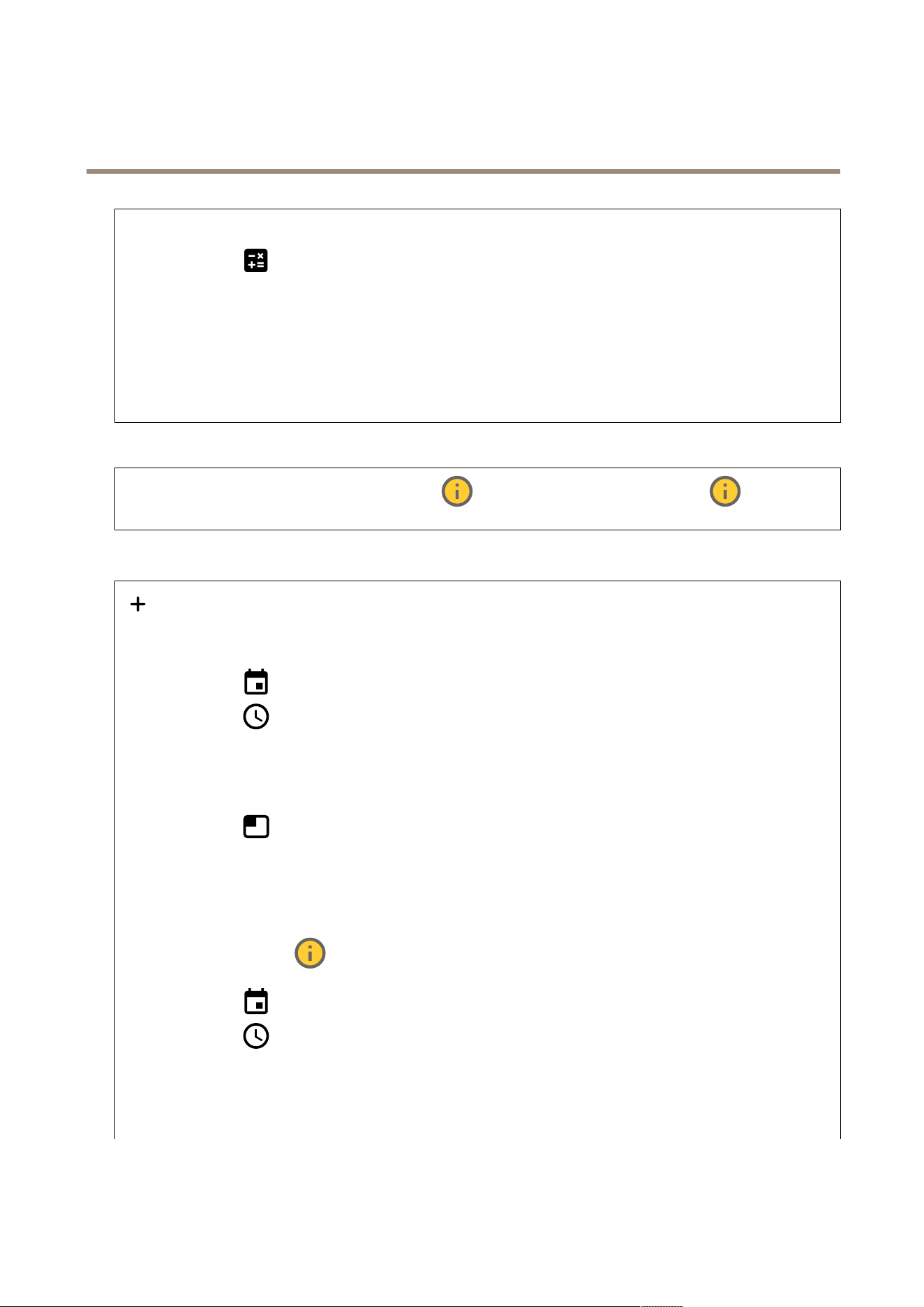
AXIS Q1686 - DLE Radar - Video Fusion Camera
The web inter face
• Average : Select to automatically adjust the bitrate over a longer time period and provide the best possible image
quality based on the available storage.
- Click to calculate the target bitrate based on available storage, retention time, and bitrate limit.
- T arget bitrate : Enter desired target bitrate.
- Retention time : Enter the number of days to keep the recordings.
- Storage : Shows the estimated storage that can be used for the stream.
- Maximum bitrate : T urn on to set a bitrate limit.
- Bitrate limit : Enter a bitrate limit that is higher than the target bitrate.
• Maximum : Select to set a maximum instant bitrate of the stream based on your network bandwidth.
- Maximum : Enter the maximum bitrate.
• V ariable : Select to allow the bitrate to vary based on the level of activity in the scene. More activity requires more
bandwidth. W e recommend this option for most situations.
Audio
Include : T urn on to use audio in the video stream. Source : Select what audio source to use. Stereo : T urn on to
include built - in audio as well as audio from an external microphone.
Overlays
: Click to add an overlay . Select the type of overlay from the dropdown list:
• T ext : Select to show a text that is integrated in the live view image and visible in all views, recordings and snapshots.
Y ou can enter your own text, and you can also include pre - congured modiers to automatically show , for example,
time, date, and frame rate.
- : Click to add the date modier %F to show yyyy - mm - dd.
- : Click to add the time modier %X to show hh:mm:ss (24 - hour clock).
- Modiers : Click to select any of the modiers shown in the list to add them to the text box. For example,
%a shows the day of the week.
- Size : Select the desired font size.
- Appearance : Select the text color and background color , for example, white text on a black background
(default).
- : Select the position of the overlay in the image.
• Image : Select to show a static image superimposed over the video stream. Y ou can use .bmp, .png, .jpeg, or .svg les.
T o upload an image, click Images . Before you upload an image, you can choose to:
- Scale with resolution : Select to automatically scale the overlay image to t the video resolution.
- Use transparency : Select and enter the RGB hexadecimal value for that color . Use the format RRGGBB .
Examples of hexadecimal values: FFFFFF for white, 000000 for black, FF0000 for red, 6633FF for blue, and
669900 for green. Only for .bmp images.
• Scene annotation : Select to show a text overlay in the video stream that stays in the same position, even
when the camera pans or tilts in another direction. Y ou can choose to only show the overlay within certain zoom levels.
- : Click to add the date modier %F to show yyyy - mm - dd.
- : Click to add the time modier %X to show hh:mm:ss (24 - hour clock).
- Modiers : Click to select any of the modiers shown in the list to add them to the text box. For example,
%a shows the day of the week.
- Size : Select the desired font size.
- Appearance : Select the text color and background color , for example, white text on a black background
(default).
43
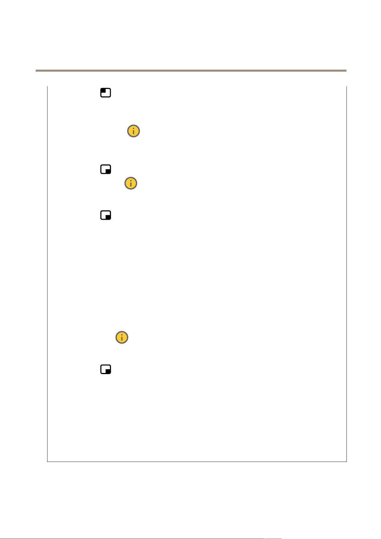
AXIS Q1686 - DLE Radar - Video Fusion Camera
The web inter face
- : Select the position of the overlay in the image. The overlay is saved and remains in the pan and
tilt coordinates of this position.
- Annotation between zoom levels (%) : Set the zoom levels which the overlay will be shown within.
- Annotation symbol : Select a symbol that appears instead of the overlay when the camera is not within the
set zoom levels.
• Streaming indicator : Select to show an animation superimposed over the video stream. The animation
indicates that the video stream is live, even if the scene doesn’t contain any motion.
- Appearance : Select the animation color and background color , for example, red animation on a transparent
background (default).
- Size : Select the desired font size.
- : Select the position of the overlay in the image.
• Widget: Linegraph : Show a graph chart that displays how a measured value changes over time.
- Title : Enter a title for the widget.
- Overlay modier : Select an overlay modier as data source. If you have created MQTT overlays, they will be
located at the end of the list.
- : Select the position of the overlay in the image.
- Size : Select the size of the overlay .
- Visible on all channels : T urn off to show only on your currently selected channel. T urn on to show on all
active channels.
- Update interval : Choose the time between data updates.
- T ransparency : Set the transparency of the entire overlay .
- Background transparency : Set the transparency only of the background of the overlay .
- P oints : T urn on to add a point to the graph line when data is updated.
- X axis
- Label : Enter the text label for the x axis.
- Time window : Enter how long time the data is visualized.
- Time unit : Enter a time unit for the x axis.
- Y axis
- Label : Enter the text label for the y axis.
- Dynamic scale : T urn on for the scale to automatically adapt to the data values. T urn off to manually enter
values for a xed scale.
- Min alarm threshold and Max alarm threshold : These values will add horizontal reference lines to the graph,
making it easier to see when the data value becomes too high or too low .
• Widget: Meter : Show a bar chart that displays the most recently measured data value.
- Title : Enter a title for the widget.
- Overlay modier : Select an overlay modier as data source. If you have created MQTT overlays, they will be
located at the end of the list.
- : Select the position of the overlay in the image.
- Size : Select the size of the overlay .
- Visible on all channels : T urn off to show only on your currently selected channel. T urn on to show on all
active channels.
- Update interval : Choose the time between data updates.
- T ransparency : Set the transparency of the entire overlay .
- Background transparency : Set the transparency only of the background of the overlay .
- P oints : T urn on to add a point to the graph line when data is updated.
- Y axis
- Label : Enter the text label for the y axis.
- Dynamic scale : T urn on for the scale to automatically adapt to the data values. T urn off to manually enter
values for a xed scale.
- Min alarm threshold and Max alarm threshold : These values will add horizontal reference lines to the bar
chart, making it easier to see when the data value becomes too high or too low .
44
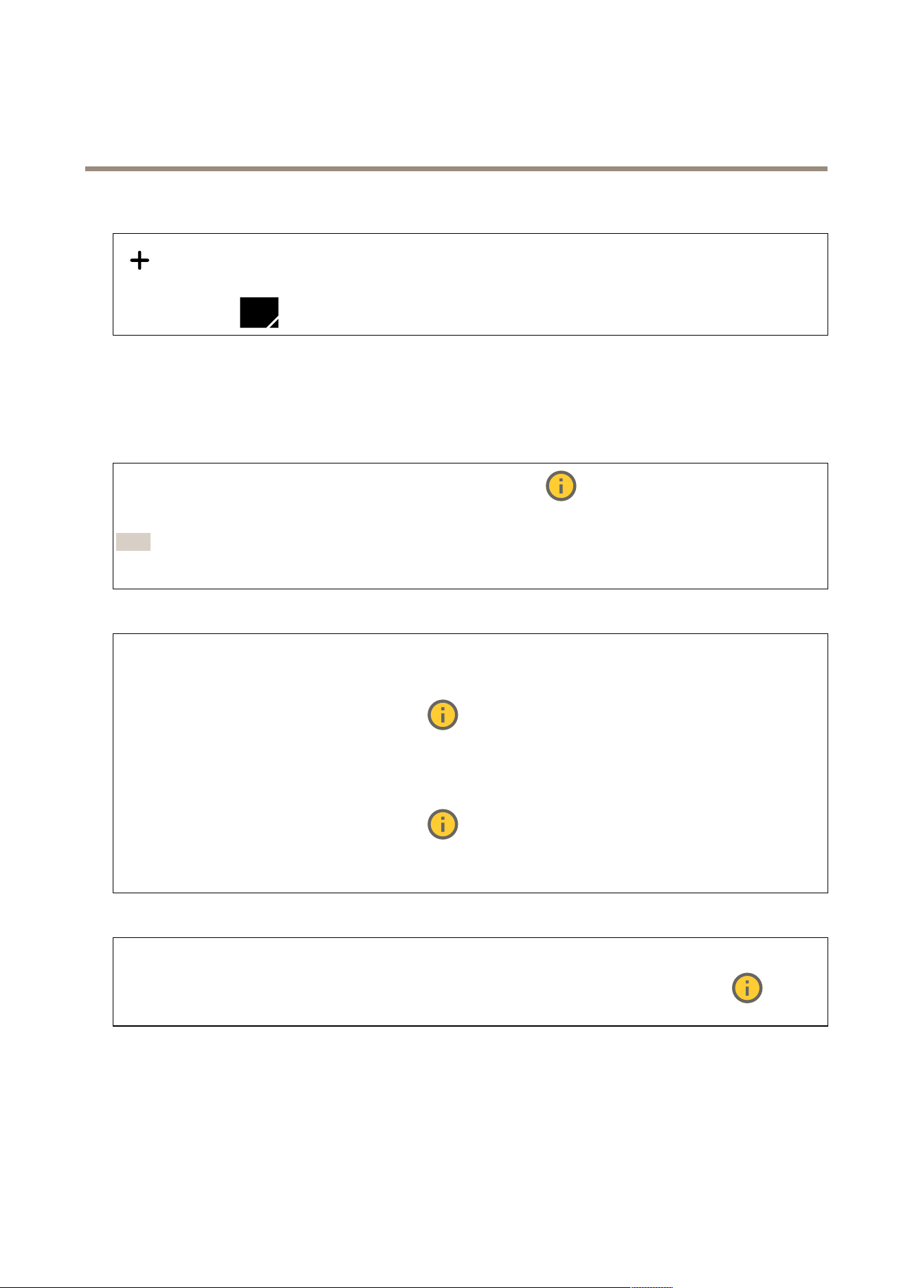
AXIS Q1686 - DLE Radar - Video Fusion Camera
The web inter face
Privacy masks
: Click to create a new privacy mask. Privacy masks : Click to change the color of all privacy masks, or to delete all privacy
masks permanently . Cell size : If you choose mosaic color , the privacy masks appear as pixilated patterns. Use the slider to change
the size of the pixels. Mask x : Click to rename, disable, or permanently delete the mask.
Radar
Settings
General
Radar transmission : Use this to turn off the radar module completely . Channel : If you have problems with multiple devices
interfering with each other , select the same channel for up to four devices that are close to each other . For most installations, select
Auto to let the devices automatically negotiate which channel to use. Mounting height : Enter the mounting height for the product.
Note
Be as specic as you can when you enter the mounting height. This helps the device visualize the radar detection in
the correct position in the image.
Detection
Detection sensitivity : Select how sensitive the radar should be. A higher value means that you get a longer detection range,
but there is also a higher risk of false alarms. A lower sensitivity decreases the number of false alarms, but it may shorten the
detection range. Radar prole : Select a prole that suits your area of interest.
• Area monitoring : T rack both large and small objects moving at lower speeds in open areas.
- Ignore stationary rotating objects : T urn on to minimize false alarms from stationary objects with
rotating movements, such as fans or turbines.
- Ignore small objects : T urn on to minimize false alarms from small objects, such as cats or rabbits.
- Ignore swaying objects : T urn on to minimize false alarms from swaying objects, such as trees, bushes,
or agpoles.
• Road monitoring : T rack vehicles moving at higher speeds in urban zones and on suburban roads
- Ignore stationary rotating objects : T urn on to minimize false alarms from stationary objects with
rotating movements, such as fans or turbines.
- Ignore swaying objects : T urn on to minimize false alarms from swaying objects, such as trees, bushes,
or agpoles.
View
Information legend : T urn on to show a legend containing the object types the radar can detect and track. Drag and drop to
move the information legend. Zone opacity : Select how opaque or transparent the coverage zone should be. Grid opacity : Select
how opaque or transparent the grid should be. Color scheme : Select a theme for the radar visualization. Rotation : Select
the preferred orientation of the radar image.
Object visualization
45
AXIS Q1686 - DLE Radar - Video Fusion Camera
The web inter face
T rail lifetime : Select how long the trail of a tracked object is visible in the radar view . Icon style : Select the icon style of the
tracked objects in the radar view . For plain triangles, select T riangle . For representative symbols, select Symbol . The icons will
point in the direction the tracked objects are moving, regardless of style.
Show information with icon : Select which information to display next to the icon of the tracked object:
• Object type : Show the object type that the radar has detected.
• Classication probability : Show how sure the radar is that the object classication is correct.
• V elocity : Show how fast the object is moving.
Stream
General
Resolution : Select the image resolution suitable for the surveillance scene. A higher resolution increases bandwidth and
storage. Frame rate : T o avoid bandwidth problems on the network or reduce storage size, you can limit the frame rate to a xed
amount. If you leave the frame rate at zero, the frame rate is kept at the highest possible rate under the current conditions. A
higher frame rate requires more bandwidth and storage capacity . P - frames : A P - frame is a predicted image that shows only the
changes in the image from the previous frame. Enter the desired number of P - frames. The higher the number , the less bandwidth is
required. However , if there is network congestion, there could be a noticeable deterioration in the video quality . Compression : Use
the slider to adjust the image compression. High compression results in a lower bitrate and lower image quality . Low compression
improves the image quality , but uses more bandwidth and storage when you record. Signed video : T urn on to add the
signed video feature to the video. Signed video protects the video from tampering by adding cryptographic signatures to the video.
Zipstream
Zipstream is a bitrate reduction technology , optimized for video surveillance, that reduces the average bitrate in an H.264 or H.265
stream in real time. Axis Zipstream applies a high bitrate in scenes where there are multiple regions of interest, for example, in scenes
with moving objects. When the scene is more static, Zipstream applies a lower bitrate, and thereby reduces the required storage.
T o learn more, see Reducing the bit rate with Axis Zipstream
Select the bitrate reduction Strength :
• Off : No bitrate reduction.
• Low : No visible quality degradation in most scenes. This is the default option and it can be used in all types
of scenes to reduce the bitrate.
• Medium : Visible effects in some scenes through less noise and a slightly lower level of detail in regions of lower
interest, for example, where there’s no movement.
• High : Visible effects in some scenes through less noise and a lower level of detail in regions of lower interest, for
example, where there’s no movement. W e recommend this level for cloud - connected devices and devices that
use local storage.
• Higher : Visible effects in some scenes through less noise and a lower level of detail in regions of lower interest,
for example, where there’s no movement.
• Extreme : Visible effects in most scenes. The bitrate is optimized for smallest possible storage.
Optimize for storage : T urn on to minimize the bitrate while maintaining quality . The optimization does not apply to the stream
shown in the web client. This can only be used if your VMS supports B - frames. T urning on Optimize for storage also turns on
Dynamic GOP . Dynamic FPS (frames per second): T urn on to allow the bandwidth to vary based on the level of activity in the
scene. More activity requires more bandwidth. Lower limit : Enter a value to adjust the frame rate between minimal fps and the
stream default fps based on scene motion. W e recommend you to use lower limit in scenes with very little motion, where the fps
could drop to 1 or lower . Dynamic GOP (Group of Pictures): T urn on to dynamically adjust the interval between I - frames based on
the level of activity in the scene. Upper limit : Enter a maximum GOP length, that is, the maximum number of P - frames between
two I - frames. An I - frame is a self - contained image frame that is independent of other frames.
Bitrate control
46
AXIS Q1686 - DLE Radar - Video Fusion Camera
The web inter face
• Average : Select to automatically adjust the bitrate over a longer time period and provide the best possible image
quality based on the available storage.
- Click to calculate the target bitrate based on available storage, retention time, and bitrate limit.
- T arget bitrate : Enter desired target bitrate.
- Retention time : Enter the number of days to keep the recordings.
- Storage : Shows the estimated storage that can be used for the stream.
- Maximum bitrate : T urn on to set a bitrate limit.
- Bitrate limit : Enter a bitrate limit that is higher than the target bitrate.
• Maximum : Select to set a maximum instant bitrate of the stream based on your network bandwidth.
- Maximum : Enter the maximum bitrate.
• V ariable : Select to allow the bitrate to vary based on the level of activity in the scene. More activity requires more
bandwidth. W e recommend this option for most situations.
Audio
Include : T urn on to use audio in the video stream. Source : Select what audio source to use. Stereo : T urn on to
include built - in audio as well as audio from an external microphone.
Map calibration
Use map calibration to upload and calibrate a reference map. This will make it easier to see where objects move in the area
covered by the radar . Upload map : Select the reference map you want to upload. Set radar position on map : Specify the position
of the radar on the map, add a reference point straight in front of the radar and type the distance between the radar and the
reference point. Click Calibrate to start the calibration. The result of the calibration is a reference map that displays the radar
coverage in the appropriate scale.
Lanes
Lanes improve the radar’s performance and ability to track vehicles when monitoring lanes on a road. Add one lane in the radar
for each actual lane you are monitoring. Add lane : Click to add a new lane. Use the mouse to modify the shape of the
lane you have added. : Click to expand and edit the name of the lane. : Click to delete the lane. Lanes enabled :
T urn on to activate the lanes you have added.
Exclude zones
An exclude zone is an area in which moving objects are ignored. Use exclude zones if there are areas inside a scenario that trigger
a lot of unwanted alarms. : Click to create a new exclude zone.T o modify an exclude zone, select it in the list. T rack
passing objects : T urn on to track objects that pass through the exclude zone. The passing objects keep their track IDs and are
visible throughout the zone. Objects that appear from within the exclude zone will not be tracked. Zone shape presets : Select
the initial shape of the exclude zone.
• Cover everything : Select to set an exclude zone that covers the entire radar coverage area.
• Reset to box : Select to place a rectangular exclude zone in the middle of the coverage area.
T o modify the shape of the zone, drag and drop any of the points on the lines. T o remove a point, right - click on it.
47
AXIS Q1686 - DLE Radar - Video Fusion Camera
The web inter face
Scenarios
A scenario is a combination of triggering conditions, as well as scene and detection settings. : Click to create a new
scenario. Y ou can create up to 20 scenarios.
T riggering conditions : Select the condition that will trigger alarms.
• Movement in area : Select if you want the scenario to trigger on objects moving in an area.
• Line crossing : Select if you want to the scenario to trigger on objects crossing one, or two, lines.
Scene : Dene the area or lines in the scenario where moving objects will trigger alarms.
• For Movement in area , select one of the shape presets to modify the area.
• For Line crossing , drag and drop the line in the scene. T o create more points on a line, click and drag anywhere
on it. T o remove a point, right - click on it.
- Require crossing of two lines : T urn on if the object must pass two lines before the scenario triggers an alarm.
- Change direction: T urn on if you want the scenario to trigger an alarm when objects cross the line in
the other direction.
Detection settings : Dene the trigger criteria for the scenario.
• For Movement in area :
- Ignore short - lived objects : Set the delay in seconds from when the radar detects the object to when the
scenario triggers an alarm. This can help to reduce false alarms.
- T rigger on object type : Select the type of objects (human, vehicle, unknown) you want the scenario to
trigger on.
- Speed limit : T rigger on objects moving at speeds within a specic range.
- Invert : Select if you want to trigger on speeds above and below the set speed limit.
• For Line crossing :
- Ignore short - lived objects : Set the delay in seconds from when the radar detects the object to when the
scenario triggers an action. This can help to reduce false alarms. This option is not available for objects
crossing two lines.
- Max time between crossings : Set the max time between crossing the rst line and the second line. This
option is only available for objects crossing two lines.
- T rigger on object type : Select the type of objects (human, vehicle, unknown) you want the scenario to
trigger on.
- Speed limit : T rigger on objects moving at speeds within a specic range.
- Invert : Select if you want to trigger on speeds above and below the set speed limit.
Alarm settings : Dene the criteria for the alarm.
• Minimum trigger duration : Set the minimum duration for the triggered alarm.
Overlays
: Click to add an overlay . Select the type of overlay from the dropdown list:
• T ext : Select to show a text that is integrated in the live view image and visible in all views, recordings and snapshots.
Y ou can enter your own text, and you can also include pre - congured modiers to automatically show , for example,
time, date, and frame rate.
- : Click to add the date modier %F to show yyyy - mm - dd.
- : Click to add the time modier %X to show hh:mm:ss (24 - hour clock).
- Modiers : Click to select any of the modiers shown in the list to add them to the text box. For example,
%a shows the day of the week.
- Size : Select the desired font size.
- Appearance : Select the text color and background color , for example, white text on a black background
(default).
- : Select the position of the overlay in the image.
• Image : Select to show a static image superimposed over the video stream. Y ou can use .bmp, .png, .jpeg, or .svg les.
T o upload an image, click Images . Before you upload an image, you can choose to:
48
AXIS Q1686 - DLE Radar - Video Fusion Camera
The web inter face
- Scale with resolution : Select to automatically scale the overlay image to t the video resolution.
- Use transparency : Select and enter the RGB hexadecimal value for that color . Use the format RRGGBB .
Examples of hexadecimal values: FFFFFF for white, 000000 for black, FF0000 for red, 6633FF for blue, and
669900 for green. Only for .bmp images.
• Scene annotation : Select to show a text overlay in the video stream that stays in the same position, even
when the camera pans or tilts in another direction. Y ou can choose to only show the overlay within certain zoom levels.
- : Click to add the date modier %F to show yyyy - mm - dd.
- : Click to add the time modier %X to show hh:mm:ss (24 - hour clock).
- Modiers : Click to select any of the modiers shown in the list to add them to the text box. For example,
%a shows the day of the week.
- Size : Select the desired font size.
- Appearance : Select the text color and background color , for example, white text on a black background
(default).
- : Select the position of the overlay in the image. The overlay is saved and remains in the pan and
tilt coordinates of this position.
- Annotation between zoom levels (%) : Set the zoom levels which the overlay will be shown within.
- Annotation symbol : Select a symbol that appears instead of the overlay when the camera is not within the
set zoom levels.
• Streaming indicator : Select to show an animation superimposed over the video stream. The animation
indicates that the video stream is live, even if the scene doesn’t contain any motion.
- Appearance : Select the animation color and background color , for example, red animation on a transparent
background (default).
- Size : Select the desired font size.
- : Select the position of the overlay in the image.
• Widget: Linegraph : Show a graph chart that displays how a measured value changes over time.
- Title : Enter a title for the widget.
- Overlay modier : Select an overlay modier as data source. If you have created MQTT overlays, they will be
located at the end of the list.
- : Select the position of the overlay in the image.
- Size : Select the size of the overlay .
- Visible on all channels : T urn off to show only on your currently selected channel. T urn on to show on all
active channels.
- Update interval : Choose the time between data updates.
- T ransparency : Set the transparency of the entire overlay .
- Background transparency : Set the transparency only of the background of the overlay .
- P oints : T urn on to add a point to the graph line when data is updated.
- X axis
- Label : Enter the text label for the x axis.
- Time window : Enter how long time the data is visualized.
- Time unit : Enter a time unit for the x axis.
- Y axis
- Label : Enter the text label for the y axis.
- Dynamic scale : T urn on for the scale to automatically adapt to the data values. T urn off to manually enter
values for a xed scale.
- Min alarm threshold and Max alarm threshold : These values will add horizontal reference lines to the graph,
making it easier to see when the data value becomes too high or too low .
• Widget: Meter : Show a bar chart that displays the most recently measured data value.
- Title : Enter a title for the widget.
- Overlay modier : Select an overlay modier as data source. If you have created MQTT overlays, they will be
located at the end of the list.
- : Select the position of the overlay in the image.
49
AXIS Q1686 - DLE Radar - Video Fusion Camera
The web inter face
- Size : Select the size of the overlay .
- Visible on all channels : T urn off to show only on your currently selected channel. T urn on to show on all
active channels.
- Update interval : Choose the time between data updates.
- T ransparency : Set the transparency of the entire overlay .
- Background transparency : Set the transparency only of the background of the overlay .
- P oints : T urn on to add a point to the graph line when data is updated.
- Y axis
- Label : Enter the text label for the y axis.
- Dynamic scale : T urn on for the scale to automatically adapt to the data values. T urn off to manually enter
values for a xed scale.
- Min alarm threshold and Max alarm threshold : These values will add horizontal reference lines to the bar
chart, making it easier to see when the data value becomes too high or too low .
Radar PTZ autotracking
P air the radar with a PTZ camera to use radar autotracking. T o establish the connection, go to System > Edge - to - edge .
Congure initial settings: Camera mounting height : The distance from the ground to the height of the mounted PTZ camera. P an
alignment : P an the PTZ camera so that it points in the same direction as the radar . Click on the IP address of the PTZ camera to
access it. Save pan offset : Click to save the pan alignment. Ground incline offset : Use the ground incline offset to ne tune the
camera’s tilt. If the ground is sloped, or if the camera is not mounted horizontally , the camera may aim too high or too low when
tracking an object. Done : Click to save your settings and continue with the conguration.
Congure PTZ autotracking: T rack : Select if you want to track humans, vehicles and/or unknown objects. T racking : T urn on to start
tracking objects with the PTZ camera. The tracking automatically zooms in on an object, or a group of objects, to keep them in
the view of the camera. Object switching : If the radar detects multiple objects that won't t in the PTZ camera's view , the PTZ
camera tracks the object that the radar gives the highest priority , and ignores the others. Object hold time : Determines for how
many seconds the PTZ camera should track each object. Return to home : T urn on to make the PTZ camera return to its home
position when the radar no longer tracks any objects. Return to home timeout : Determines how long the PTZ camera should
stay at the tracked objects last known position before returning to home. Zoom : Use the slider to ne tune the zoom of the PTZ
camera. Recongure installation : Click to clear all settings and go back to the initial conguration.
Analytics
AXIS Object Analytics
Start : Click to start AXIS Object Analytics. The application will run in the background, and you can create rules for events based on
the application’s current settings. Open : Click to open AXIS Object Analytics. The application opens up in a new window where you
can congure its settings. Not installed : AXIS Object Analytics is not installed on this device. Upgrade AXIS OS to the
latest version to get the latest version of the application.
Audio
Device settings
Input : T urn on or off audio input. Shows the type of input.
50
AXIS Q1686 - DLE Radar - Video Fusion Camera
The web inter face
Input type : Select the type of input, for instance, if it’s internal microphone or line. P ower type : Select power type
for your input. Apply changes : Apply your selection. Echo cancellation : T urn on to remove echoes during two - way
communication. Separate gain controls : T urn on to adjust the gain separately for the different input types. Automatic
gain control : T urn on to dynamically adapt the gain to changes in the sound. Gain : Use the slider to change the gain.
Click the microphone icon to mute or unmute.
Output : Shows the type of output.
Gain : Use the slider to change the gain. Click the speaker icon to mute or unmute.
Stream
Encoding : Select the encoding to use for the input source streaming. Y ou can only choose encoding if audio input is turned on. If
audio input is turned off, click Enable audio input to turn it on.
Echo cancellation : T urn on to remove echoes during two - way communication.
Audio clips
Add clip : Add a new audio clip. Y ou can use .au, .mp3, .opus, .vorbis, .wav les. Play the audio clip. Stop
playing the audio clip. The context menu contains:
• Rename : Change the name of the audio clip.
• Create link : Create a URL that, when used, plays the audio clip on the device. Specify the volume and number
of times to play the clip.
• Download : Download the audio clip to your computer .
• Delete : Delete the audio clip from the device.
Audio enhancement
Input
T en Band Graphic Audio Equalizer : T urn on to adjust the level of different frequency bands within an audio signal. This feature is
for advanced users with audio conguration experience. T alkback range : Choose the operational range to gather audio
content. An increase to the operational range cause a reduction of simultaneous two - way communication capabilities. V oice
enhancement : T urn on to enhance the voice content in relation to other sounds.
Recordings
Ongoing recordings : Show all ongoing recordings on the device. Start a recording on the device. Choose which
storage device to save to. Stop a recording on the device. T riggered recordings will end when manually stopped or when the
device is shut down. Continuous recordings will continue until manually stopped. Even if the device is shut down, the recording
will continue when the device starts up again.
5 1
AXIS Q1686 - DLE Radar - Video Fusion Camera
The web inter face
Play the recording. Stop playing the recording. Show or hide information and options about the
recording. Set export range : If you only want to export part of the recording, enter a time span. Note that if you work in a
different time zone than the location of the device, the time span is based on the device’s time zone. Encrypt : Select to set a
password for exported recordings. It will not be possible to open the exported le without the password. Click to delete a
recording. Export : Export the whole or a part of the recording.
Click to lter the recordings. From : Show recordings done after a certain point in time. T o : Show recordings up until a certain
point in time. Source : Show recordings based on source. The source refers to the sensor . Event : Show recordings based
on events. Storage : Show recordings based on storage type.
Apps
Add app : Install a new app. Find more apps : Find more apps to install. Y ou will be taken to an overview page of Axis
apps. Allow unsigned apps : T urn on to allow installation of unsigned apps. Allow root - privileged apps : T urn on to
allow apps with root privileges full access to the device. View the security updates in AXIS OS and ACAP apps.
Note
The device’s performance might be affected if you run several apps at the same time.
Use the switch next to the app name to start or stop the app. Open : Access the app’s settings. The available settings depend on the
application. Some applications don’t have any settings. The context menu can contain one or more of the following options:
• Open - source license : View information about open - source licenses used in the app.
• App log : View a log of the app events. The log is helpful when you contact support.
• Activate license with a key : If the app requires a license, you need to activate it. Use this option if your device
doesn’t have internet access.
If you don’t have a license key , go to axis.com/products/analytics . Y ou need a license code and the Axis product serial
number to generate a license key .
• Activate license automatically : If the app requires a license, you need to activate it. Use this option if your device has
internet access. Y ou need a license code to activate the license.
• Deactivate the license : Deactivate the license to replace it with another license, for example, when you change from a
trial license to a full license. If you deactivate the license, you also remove it from the device.
• Settings : Congure the parameters.
• Delete : Delete the app permanently from the device. If you don’t deactivate the license rst, it remains active.
System
Time and location
Date and time
The time format depends on the web browser’s language settings.
Note
W e recommend you synchronize the device’s date and time with an NTP server .
52
AXIS Q1686 - DLE Radar - Video Fusion Camera
The web inter face
Synchronization : Select an option for the device’s date and time synchronization.
• Automatic date and time (manual NTS KE servers) : Synchronize with the secure NTP key establishment servers
connected to the DHCP server .
- Manual NTS KE servers : Enter the IP address of one or two NTP servers. When you use two NTP servers,
the device synchronizes and adapts its time based on input from both.
- Max NTP poll time : Select the maximum amount of time the device should wait before it polls the NTP
server to get an updated time.
- Min NTP poll time : Select the minimum amount of time the device should wait before it polls the NTP
server to get an updated time.
• Automatic date and time (NTP servers using DHCP) : Synchronize with the NTP servers connected to the DHCP server .
- Fallback NTP servers : Enter the IP address of one or two fallback servers.
- Max NTP poll time : Select the maximum amount of time the device should wait before it polls the NTP
server to get an updated time.
- Min NTP poll time : Select the minimum amount of time the device should wait before it polls the NTP
server to get an updated time.
• Automatic date and time (manual NTP servers) : Synchronize with NTP servers of your choice.
- Manual NTP servers : Enter the IP address of one or two NTP servers. When you use two NTP servers, the
device synchronizes and adapts its time based on input from both.
- Max NTP poll time : Select the maximum amount of time the device should wait before it polls the NTP
server to get an updated time.
- Min NTP poll time : Select the minimum amount of time the device should wait before it polls the NTP
server to get an updated time.
• Custom date and time : Manually set the date and time. Click Get from system to fetch the date and time settings
once from your computer or mobile device.
Time zone : Select which time zone to use. Time will automatically adjust to daylight saving time and standard time.
• DHCP : Adopts the time zone of the DHCP server . The device must connected to a DHCP server before you can select
this option.
• Manual : Select a time zone from the drop - down list.
Note
The system uses the date and time settings in all recordings, logs, and system settings.
Device location
Enter where the device is located. Y our video management system can use this information to place the device on a map.
• Latitude : P ositive values are north of the equator .
• Longitude : P ositive values are east of the prime meridian.
• Heading : Enter the compass direction that the device is facing. 0 is due north.
• Label : Enter a descriptive name for the device.
• Save : Click to save your device location.
Regional settings
Sets the system of measurement to use in all system settings.
Metric (m, km/h) : Select for distance measurement to be in meters and speed measurement to be in kilometers per hour . U.S.
customary (ft, mph) : Select for distance measurement to be in feet and speed measurement to be in miles per hour .
Network
IPv4
53
AXIS Q1686 - DLE Radar - Video Fusion Camera
The web inter face
Assign IPv4 automatically : Select to let the network router assign an IP address to the device automatically . W e recommend
automatic IP (DHCP) for most networks. IP address : Enter a unique IP address for the device. Static IP addresses can be assigned
at random within isolated networks, provided that each address is unique. T o avoid conicts, we recommend you contact your
network administrator before you assign a static IP address. Subnet mask : Enter the subnet mask to dene what addresses are
inside the local area network. Any address outside the local area network goes through the router . Router : Enter the IP address of
the default router (gateway) used to connect devices that are attached to different networks and network segments. Fallback to
static IP address if DHCP isn’t available : Select if you want to add a static IP address to use as fallback if DHCP is unavailable
and can’t assign an IP address automatically .
Note
If DHCP isn’t available and the device uses a static address fallback, the static address is congured with a limited scope.
IPv6
Assign IPv6 automatically : Select to turn on IPv6 and to let the network router assign an IP address to the device automatically .
Hostname
Assign hostname automatically : Select to let the network router assign a hostname to the device automatically . Hostname :
Enter the hostname manually to use as an alternative way of accessing the device. The server report and system log use the
hostname. Allowed characters are A–Z, a–z, 0–9 and -.
DNS servers
Assign DNS automatically : Select to let the DHCP server assign search domains and DNS server addresses to the device
automatically . W e recommend automatic DNS (DHCP) for most networks. Search domains : When you use a hostname that is
not fully qualied, click Add search domain and enter a domain in which to search for the hostname the device uses. DNS
servers : Click Add DNS server and enter the IP address of the DNS server . This provides the translation of hostnames to IP
addresses on your network.
HTTP and HTTPS
HTTPS is a protocol that provides encryption for page requests from users and for the pages returned by the web server . The encrypted
exchange of information is governed by the use of an HTTPS certicate, which guarantees the authenticity of the server .
T o use HTTPS on the device, you must install an HTTPS certicate. Go to System > Security to create and install certicates.
Allow access through : Select if a user is allowed to connect to the device through the HTTP , HTTPS , or both HTTP and HTTPS
protocols.
Note
If you view encrypted web pages through HTTPS, you might experience a drop in performance, especially when you
request a page for the rst time.
HTTP port : Enter the HTTP port to use. The device allows port 80 or any port in the range 1 0 24 - 65535. If you are logged in as
an administrator , you can also enter any port in the range 1 - 1 0 23. If you use a port in this range, you get a warning. HTTPS
port : Enter the HTTPS port to use. The device allows port 443 or any port in the range 1 0 24 - 65535. If you are logged in as an
administrator , you can also enter any port in the range 1 - 1 0 23. If you use a port in this range, you get a warning. Certicate :
Select a certicate to enable HTTPS for the device.
Network discovery protocols
Bonjour
®
: T urn on to allow automatic discovery on the network. Bonjour name : Enter a friendly name to be visible on the network.
The default name is the device name and MAC address. UPnP
®
: T urn on to allow automatic discovery on the network. UPnP name :
Enter a friendly name to be visible on the network. The default name is the device name and MAC address. WS - Discovery : T urn on
to allow automatic discovery on the network. LLDP and CDP : T urn on to allow automatic discovery on the network. T urning LLDP
and CDP off can impact the P oE power negotiation. T o resolve any issues with the P oE power negotiation, congure the P oE
switch for hardware P oE power negotiation only .
One - click cloud connection
54

AXIS Q1686 - DLE Radar - Video Fusion Camera
The web inter face
One - click cloud connection (O3C) together with an O3C service provides easy and secure internet access to live and recorded video
from any location. For more information, see axis.com/end - to - end - solutions/hosted - services .
Allow O3C :
• One - click : This is the default setting. Press and hold the control button on the device to connect to an O3C service
over the internet. Y ou need to register the device with the O3C service within 24 hours after you press the control
button. Otherwise, the device disconnects from the O3C service. Once you register the device, Always is enabled and
the device stays connected to the O3C service.
• Always : The device constantly attempts to connect to an O3C service over the internet. Once you register the device,
it stays connected to the O3C service. Use this option if the control button on the device is out of reach.
• No : Disables the O3C service.
Proxy settings : If needed, enter the proxy settings to connect to the proxy server . Host : Enter the proxy server’s address. P ort : Enter
the port number used for access. Login and P assword : If needed, enter username and password for the proxy server . Authentication
method :
• Basic : This method is the most compatible authentication scheme for HTTP . It’s less secure than the Digest method
because it sends the username and password unencrypted to the server .
• Digest : This method is more secure because it always transfers the password encrypted across the network.
• Auto : This option lets the device select the authentication method depending on the supported methods. It prioritizes
the Digest method over the Basic method.
Owner authentication key (OAK) : Click Get key to fetch the owner authentication key . This is only possible if the device is
connected to the internet without a rewall or proxy .
SNMP
The Simple Network Management Protocol (SNMP) allows remote management of network devices.
SNMP : Select the version of SNMP to use.
• v1 and v2c :
- Read community : Enter the community name that has read - only access to all supported SNMP objects. The
default value is public .
- Write community : Enter the community name that has read or write access to all supported SNMP objects
(except read - only objects). The default value is write .
- Activate traps : T urn on to activate trap reporting. The device uses traps to send messages for important
events or status changes to a management system. In the web interface, you can set up traps for SNMP v1
and v2c. T raps are automatically turned off if you change to SNMP v3 or turn off SNMP . If you use SNMP v3,
you can set up traps through the SNMP v3 management application.
- T rap address : Enter the IP address or host name of the management server .
- T rap community : Enter the community to use when the device sends a trap message to the management
system.
- T raps :
- Cold start : Sends a trap message when the device starts.
- W arm start : Sends a trap message when you change an SNMP setting.
- Link up : Sends a trap message when a link changes from down to up.
- Authentication failed : Sends a trap message when an authentication attempt fails.
Note
All Axis Video MIB traps are enabled when you turn on SNMP v1 and v2c traps. For more information, see
AXIS OS P ortal > SNMP .
• v3 : SNMP v3 is a more secure version, which provides encryption and secure passwords. T o use SNMP v3, we
recommend you to activate HTTPS, as the password is then sent through HTTPS. This also prevents unauthorized
parties’ access to unencrypted SNMP v1 and v2c traps. If you use SNMP v3, you can set up traps through the SNMP v3
management application.
- P assword for the account “initial” : Enter the SNMP password for the account named “initial”. Although the
password can be sent without activating HTTPS, we don’t recommend it. The SNMP v3 password can only
be set once, and preferably only when HTTPS is enabled. Once the password is set, the password eld is no
longer displayed. T o set the password again, you must reset the device to factory default settings.
55
AXIS Q1686 - DLE Radar - Video Fusion Camera
The web inter face
P ower over Ethernet
Security
Certicates
Certicates are used to authenticate devices on a network. The device supports two types of certicates:
• Client/server certicates
A client/server certicate validates the device’s identity , and can be self - signed or issued by a Certicate Authority (CA).
A self - signed certicate offers limited protection and can be used before a CA - issued certicate has been obtained.
• CA certicates
Y ou can use a CA certicate to authenticate a peer certicate, for example to validate the identity of an authentication
server when the device connects to a network protected by IEEE 80 2.1X. The device has several pre - installed CA
certicates.
These formats are supported:
• Certicate formats: .PEM, .CER, and .PFX
• Private key formats: PKCS#1 and PKCS#12
Important
If you reset the device to factory default, all certicates are deleted. Any pre - installed CA certicates are reinstalled.
Add certicate : Click to add a certicate.
• More : Show more elds to ll in or select.
• Secure keystore : Select to use Secure element or T rusted Platform Module 2.0 to securely store the private key . For
more information on which secure keystore to select, go to help.axis.com/en - us/axis - os#cryptographic - support .
• K ey type : Select the default or a different encryption algorithm from the drop - down list to protect the certicate.
The context menu contains:
• Certicate information : View an installed certicate’s properties.
• Delete certicate : Delete the certicate.
• Create certicate signing request : Create a certicate signing request to send to a registration authority to apply
for a digital identity certicate.
Secure keystore :
• Secure element (CC EAL6+) : Select to use secure element for secure keystore.
• T rusted Platform Module 2.0 (CC EAL4+, FIPS 140 - 2 Level 2) : Select to use TPM 2.0 for secure keystore.
Network access control and encryption
IEEE 80 2.1x IEEE 80 2.1x is an IEEE standard for port - based network admission control providing secure authentication of wired
and wireless network devices. IEEE 80 2.1x is based on EAP (Extensible Authentication Protocol).T o access a network protected
by IEEE 80 2.1x, network devices must authenticate themselves. The authentication is performed by an authentication server ,
typically a RADIUS server (for example, FreeRADIUS and Microsoft Internet Authentication Server). IEEE 80 2.1AE MACsec IEEE
80 2.1AE MACsec is an IEEE standard for media access control (MAC) security that denes connectionless data condentiality
and integrity for media access independent protocols. Certicates When congured without a CA certicate, server certicate
validation is disabled and the device tries to authenticate itself regardless of what network it is connected to.When using a
certicate, in Axis' implementation, the device and the authentication server authenticate themselves with digital certicates
using EAP - TLS (Extensible Authentication Protocol - T ransport Layer Security).T o allow the device to access a network protected
through certicates, you must install a signed client certicate on the device. Authentication method : Select an EAP type used for
authentication. Client certicate : Select a client certicate to use IEEE 80 2.1x. The authentication server uses the certicate
to validate the client’s identity . CA certicates : Select CA certicates to validate the authentication server’s identity . When no
certicate is selected, the device tries to authenticate itself regardless of what network it is connected to. EAP identity : Enter the
user identity associated with the client certicate. EAPOL version : Select the EAPOL version that is used in the network switch. Use
IEEE 80 2.1x : Select to use the IEEE 80 2.1x protocol.These settings are only available if you use IEEE 80 2.1x PEAP - MSCHAPv2 as
the authentication method:
• P assword : Enter the password for your user identity .
• P eap version : Select the P eap version that is used in the network switch.
• Label : Select 1 to use client EAP encryption; select 2 to use client PEAP encryption. Select the Label that the network
switch uses when using P eap version 1.
56
AXIS Q1686 - DLE Radar - Video Fusion Camera
The web inter face
These settings are only available if you use IEEE 80 2.1ae MACsec (Static CAK/Pre - Shared K ey) as the authentication method:
• K ey agreement connectivity association key name : Enter the connectivity association name (CKN). It must be 2 to 64
(divisible by 2) hexadecimal characters. The CKN must be manually congured in the connectivity association and
must match on both ends of the link to initially enable MACsec.
• K ey agreement connectivity association key : Enter the connectivity association key (CAK). It should be either 32
or 64 hexadecimal characters long. The CAK must be manually congured in the connectivity association and must
match on both ends of the link to initially enable MACsec.
Prevent brute - force attacks
Blocking : T urn on to block brute - force attacks. A brute - force attack uses trial - and - error to guess login info or encryption
keys. Blocking period : Enter the number of seconds to block a brute - force attack. Blocking conditions : Enter the number of
authentication failures allowed per second before the block starts. Y ou can set the number of failures allowed both on page
level and device level.
Firewall
Activate : T urn on the rewall.
Default P olicy : Select the default state for the rewall.
• Allow: Allows all connections to the device. This option is set by default.
• Deny: Denies all connections to the device.
T o make exceptions to the default policy , you can create rules that allows or denies connections to the device from specic
addresses, protocols, and ports.
• Address : Enter an address in IPv4/IPv6 or CIDR format that you want to allow or deny access to.
• Protocol : Select a protocol that you want to allow or deny access to.
• P ort : Enter a port number that you want to allow or deny access to. Y ou can add a port number between 1 and 65535.
• P olicy : Select the policy of the rule.
: Click to create another rule.
Add rules: Click to add the rules that you have dened.
• Time in seconds: Set a time limit for testing the rules. The default time limit is set to 300 seconds. T o activate the
rules straight away , set the time to 0 seconds.
• Conrm rules: Conrm the rules and their time limit. If you have set a time limit of more than 1 second, the rules will
be active during this time. If you have set the time to 0 , the rules will be active straight away .
P ending rules : An overview of the latest tested rules that you are yet to conrm.
Note
The rules that have a time limit appear under Active rules until the displayed timer runs out, or until you conrm them. If
you don't conrm them, they will appear under P ending rules once the timer runs out, and the rewall will revert to the
previously dened settings. If you conrm them, they will replace the current active rules.
Conrm rules : Click to activate the pending rules. Active rules : An overview of the rules you are currently running on the device.
: Click to delete an active rule. : Click to delete all rules, both pending and active.
Custom signed AXIS OS certicate
T o install test software or other custom software from Axis on the device, you need a custom signed AXIS OS certicate. The
certicate veries that the software is approved by both the device owner and Axis. The software can only run on a specic device
which is identied by its unique serial number and chip ID. Only Axis can create custom signed AXIS OS certicates, since Axis
holds the key to sign them. Install : Click to install the certicate. Y ou need to install the certicate before you install the
software. The context menu contains:
• Delete certicate : Delete the certicate.
57
AXIS Q1686 - DLE Radar - Video Fusion Camera
The web inter face
Accounts
Accounts
Add account : Click to add a new account. Y ou can add up to 1 00 accounts. Account : Enter a unique account name. New
password : Enter a password for the account. P asswords must be 1 to 64 characters long. Only ASCII printable characters (code
32 to 126) are allowed in the password, for example, letters, numbers, punctuation, and some symbols. Repeat password : Enter
the same password again. Privileges :
• Administrator : Has full access to all settings. Administrators can also add, update, and remove other accounts.
• Operator : Has access to all settings except:
- All System settings.
The context menu contains: Update account : Edit the account properties. Delete account : Delete the account. Y ou can’t
delete the root account.
Anonymous access
Allow anonymous viewing : T urn on to allow anyone access the device as a viewer without logging in with an account. Allow
anonymous PTZ operating : T urn on to allow anonymous users to pan, tilt, and zoom the image.
SSH accounts
Add SSH account : Click to add a new SSH account.
• Restrict root access : T urn on to restrict functionality that requires root access.
• Enable SSH : T urn on to use SSH service.
Account : Enter a unique account name. New password : Enter a password for the account. P asswords must be 1 to 64 characters
long. Only ASCII printable characters (code 32 to 126) are allowed in the password, for example, letters, numbers, punctuation,
and some symbols. Repeat password : Enter the same password again. Comment : Enter a comment (optional). The context
menu contains: Update SSH account : Edit the account properties. Delete SSH account : Delete the account. Y ou can’t delete the
root account.
OpenID Conguration
Important
If you can't use OpenID to sign in, use the Digest or Basic credentials you used when you congured OpenID to sign in.
Client ID : Enter the OpenID username. Outgoing Proxy : Enter the proxy address for the OpenID connection to use a proxy
server . Admin claim : Enter a value for the admin role. Provider URL : Enter the web link for the API endpoint authentication. Format
should be https://[insert URL]/.well - known/openid - conguration Operator claim : Enter a value for the operator role. Require claim :
Enter the data that should be in the token. Viewer claim : Enter the value for the viewer role. Remote user : Enter a value to identify
remote users. This assists to display the current user in the device’s web interface. Scopes : Optional scopes that could be part of
the token. Client secret : Enter the OpenID password Save : Click to save the OpenID values. Enable OpenID : T urn on to close current
connection and allow device authentication from the provider URL.
Events
Rules
A rule denes the conditions that triggers the product to perform an action. The list shows all the currently congured rules in
the product.
Note
Y ou can create up to 256 action rules.
58
AXIS Q1686 - DLE Radar - Video Fusion Camera
The web inter face
Add a rule : Create a rule. Name : Enter a name for the rule. W ait between actions : Enter the minimum time (hh:mm:ss)
that must pass between rule activations. It is useful if the rule is activated by , for example, day - night mode conditions, to avoid
that small light changes during sunrise and sunset activate the rule repeatedly . Condition : Select a condition from the list. A
condition must be met for the device to perform an action. If multiple conditions are dened, all of them must be met to trigger
the action. For information about specic conditions, see Get started with rules for events . Use this condition as a trigger : Select
to make this rst condition function only as a starting trigger . It means that once the rule is activated, it remains active for as long
as all the other conditions are met, no matter the state of the rst condition. If you don’t select this option, the rule will simply be
active whenever all the conditions are met. Invert this condition : Select if you want the condition to be the opposite of your
selection. Add a condition : Click to add an additional condition. Action : Select an action from the list and enter its
required information. For information about specic actions, see Get started with rules for events .
Recipients
Y ou can set up your device to notify recipients about events or send les. The list shows all the recipients currently congured in the
product, along with information about their conguration.
Note
Y ou can create up to 20 recipients.
Add a recipient : Click to add a recipient. Name : Enter a name for the recipient. T ype : Select from the list:
• FTP
- Host : Enter the server's IP address or hostname. If you enter a hostname, make sure that a DNS server is
specied under System > Network > IPv4 and IPv6 .
- P ort : Enter the port number used by the FTP server . The default is 2 1.
- Folder : Enter the path to the directory where you want to store les. If this directory doesn’t already exist
on the FTP server , you will get an error message when uploading les.
- Username : Enter the username for the login.
- P assword : Enter the password for the login.
- Use temporary le name : Select to upload les with temporary , automatically generated lenames. The
les get renamed to the desired names when the upload completes. If the upload is aborted/interrupted,
you don’t get any corrupt les. However , you probably still get the temporary les. This way you know
that all les that have the desired name are correct.
- Use passive FTP : Under normal circumstances, the product simply requests the target FTP server to open the
data connection. The device actively initiates both the FTP control and data connections to the target server .
This is normally needed if there is a rewall between the device and the target FTP server .
• HTTP
- URL : Enter the network address to the HTTP server and the script that will handle the request. For example,
http://192.168.254.1 0/cgi - bin/notify .cgi.
- Username : Enter the username for the login.
- P assword : Enter the password for the login.
- Proxy : T urn on and enter the required information if a proxy server must be passed to connect to the HTTP
server .
• HTTPS
- URL : Enter the network address to the HTTPS server and the script that will handle the request. For example,
https://192.168.254.1 0/cgi - bin/notify .cgi.
- V alidate server certicate : Select to validate the certicate that was created by HTTPS server .
- Username : Enter the username for the login.
- P assword : Enter the password for the login.
- Proxy : T urn on and enter the required information if a proxy server must be passed to connect to the HTTPS
server .
• Network storage
Y ou can add network storage such as NAS (network - attached storage) and use it as a recipient to store les. The les
are stored in the Matroska (MKV) le format.
59
AXIS Q1686 - DLE Radar - Video Fusion Camera
The web inter face
- Host : Enter the IP address or hostname for the network storage.
- Share : Enter the name of the share on the host.
- Folder : Enter the path to the directory where you want to store les.
- Username : Enter the username for the login.
- P assword : Enter the password for the login.
• SFTP
- Host : Enter the server's IP address or hostname. If you enter a hostname, make sure that a DNS server is
specied under System > Network > IPv4 and IPv6 .
- P ort : Enter the port number used by the SFTP server . The default is 22.
- Folder : Enter the path to the directory where you want to store les. If this directory doesn’t already exist on
the SFTP server , you will get an error message when uploading les.
- Username : Enter the username for the login.
- P assword : Enter the password for the login.
- SSH host public key type (MD5) : Enter the ngerprint of the remote host’s public key (a 32 - digit
hexadecimal string). The SFTP client supports SFTP servers using SSH - 2 with RSA, DSA, ECDSA, and ED255 19
host key types. RSA is the preferred method during negotiation, followed by ECDSA, ED255 19, and DSA. Make
sure to enter the right MD5 host key that is used by your SFTP server . While the Axis device supports both
MD5 and SHA - 256 hash keys, we recommend using SHA - 256 due to stronger security over MD5. For more
information on how to congure an SFTP server with an Axis device, go to the AXIS OS P ortal .
- SSH host public key type (SHA256) : Enter the ngerprint of the remote host’s public key (a 43 - digit Base64
encoded string). The SFTP client supports SFTP servers using SSH - 2 with RSA, DSA, ECDSA, and ED255 19 host
key types. RSA is the preferred method during negotiation, followed by ECDSA, ED255 19, and DSA. Make
sure to enter the right MD5 host key that is used by your SFTP server . While the Axis device supports both
MD5 and SHA - 256 hash keys, we recommend using SHA - 256 due to stronger security over MD5. For more
information on how to congure an SFTP server with an Axis device, go to the AXIS OS P ortal .
- Use temporary le name : Select to upload les with temporary , automatically generated lenames. The
les get renamed to the desired names when the upload completes. If the upload is aborted or interrupted,
you don’t get any corrupt les. However , you probably still get the temporary les. This way , you know
that all les that have the desired name are correct.
• SIP or VMS :
SIP : Select to make a SIP call.
VMS : Select to make a VMS call.
- From SIP account : Select from the list.
- T o SIP address : Enter the SIP address.
- T est : Click to test that your call settings works.
• Email
- Send email to : Enter the email address to send emails to. T o enter multiple addresses, use commas to
separate them.
- Send email from : Enter the email address of the sending server .
- Username : Enter the username for the mail server . Leave this eld empty if the mail server does not
require authentication.
- P assword : Enter the password for the mail server . Leave this eld empty if the mail server does not require
authentication.
- Email server (SMTP) : Enter the name of the SMTP server , for example, smtp.gmail.com, smtp.mail.yahoo.com.
- P ort : Enter the port number for the SMTP server , using values in the range 0 - 65535. The default value is 587.
- Encryption : T o use encryption, select either SSL or TLS.
- V alidate server certicate : If you use encryption, select to validate the identity of the device. The certicate
can be self - signed or issued by a Certicate Authority (CA).
- POP authentication : T urn on to enter the name of the POP server , for example, pop.gmail.com.
Note
Some email providers have security lters that prevent users from receiving or viewing large amount of
attachments, from receiving scheduled emails and similar . Check the email provider's security policy to avoid
your email account being locked or missing out on your expected emails.
• T CP
- Host : Enter the server's IP address or hostname. If you enter a hostname, make sure that a DNS server is
specied under System > Network > IPv4 and IPv6 .
- P ort : Enter the port number used to access the server .
60
AXIS Q1686 - DLE Radar - Video Fusion Camera
The web inter face
T est : Click to test the setup. The context menu contains: View recipient : Click to view all the recipient details. Copy
recipient : Click to copy a recipient. When you copy , you can make changes to the new recipient. Delete recipient : Click to delete
the recipient permanently .
Schedules
Schedules and pulses can be used as conditions in rules. The list shows all the schedules and pulses currently congured in the
product, along with information about their conguration. Add schedule : Click to create a schedule or pulse.
Manual triggers
Y ou can use the manual trigger to manually trigger a rule. The manual trigger can, for example, be used to validate actions
during product installation and conguration.
MQTT
MQTT (Message Queuing T elemetry T ransport) is a standard messaging protocol for the Internet of Things (IoT). It was designed for
simplied IoT integration and is used in a wide variety of industries to connect remote devices with a small code footprint and
minimal network bandwidth. The MQTT client in Axis device software can simplify integration of data and events produced in the
device to systems which are not video management software (VMS).Set up the device as an MQTT client. MQTT communication is
based on two entities, the clients and the broker . The clients can send and receive messages. The broker is responsible for routing
messages between clients.Y ou can learn more about MQTT in AXIS OS P ortal .
ALPN
ALPN is a TLS/SSL extension that allows for the selection of an application protocol during the handshake phase of the connection
between the client and server . This is used to enable MQTT trafc over the same port that is used for other protocols, such as HTTP .
In some cases, there might not be a dedicated port open for MQTT communication. A solution in such cases is to use ALPN to
negotiate the use of MQTT as the application protocol on a standard port, allowed by the rewalls.
MQTT client
Connect : T urn on or off the MQTT client. Status : Shows the current status of the MQTT client. BrokerHost : Enter the hostname or
IP address of the MQTT server . Protocol : Select which protocol to use. P ort : Enter the port number .
• 1883 is the default value for MQTT over T CP
• 8883 is the default value for MQTT over SSL
• 80 is the default value for MQTT over W ebSocket
• 443 is the default value for MQTT over W ebSocket Secure
ALPN protocol : Enter the ALPN protocol name provided by your MQTT broker provider . This is only applicable with MQTT over SSL
and MQTT over W ebSocket Secure. Username : Enter the username that the client will use to access the server . P assword : Enter
a password for the username. Client ID : Enter a client ID. The client identier is sent to the server when the client connects to
it. Clean session : Controls the behavior at connection and disconnection time. When selected, the state information is discarded at
connect and disconnect. HTTP proxy : A URL with a maximum length of 255 bytes. Y ou can leave the eld empty if you don't want
to use an HTTP proxy . HTTPS proxy : A URL with a maximum length of 255 bytes. Y ou can leave the eld empty if you don't want to
use an HTTPS proxy . K eep alive interval : Enables the client to detect when the server is no longer available without having to wait
for the long T CP/IP timeout. Timeout : The time interval in seconds to allow a connect to complete. Default value: 60 Device topic
prex : Used in the default values for the topic in the connect message and L WT message on the MQTT client tab , and in the
publication conditions on the MQTT publication tab . Reconnect automatically : Species whether the client should reconnect
automatically after a disconnect. Connect message Species if a message should be sent out when a connection is established. Send
message : T urn on to send messages. Use default : T urn off to enter your own default message. T opic : Enter the topic for the default
message. P ayload : Enter the content for the default message. Retain : Select to keep the state of client on this T opicQoS : Change
the QoS layer for the packet ow . Last Will and T estament message The Last Will T estament (L WT) lets a client provide a testament
along with its credentials when connecting to the broker . If the client disconnects ungracefully at some point later (maybe because
his power source died), it can let the broker deliver a message to other clients. This L WT message has the same form as an ordinary
message and gets routed via the same mechanics. Send message : T urn on to send messages. Use default : T urn off to enter your
6 1
AXIS Q1686 - DLE Radar - Video Fusion Camera
The web inter face
own default message. T opic : Enter the topic for the default message. P ayload : Enter the content for the default message. Retain :
Select to keep the state of client on this T opicQoS : Change the QoS layer for the packet ow .
MQTT publication
Use default topic prex : Select to use the default topic prex, that is dened in the device topic prex in the MQTT client
tab . Include topic name : Select to include the topic that describes the condition in the MQTT topic. Include topic namespaces :
Select to include ONVIF topic namespaces in the MQTT topic. Include serial number : Select to include the device’s serial number in
the MQTT payload. Add condition : Click to add a condition. Retain : Denes which MQTT messages are sent as retained.
• None : Send all messages as non - retained.
• Property : Send only stateful messages as retained.
• All : Send both stateful and stateless messages as retained.
QoS : Select the desired level for the MQTT publication.
MQTT subscriptions
Add subscription : Click to add a new MQTT subscription. Subscription lter : Enter the MQTT topic that you want to
subscribe to. Use device topic prex : Add the subscription lter as prex to the MQTT topic. Subscription type :
• Stateless : Select to convert MQTT messages into a stateless message.
• Stateful : Select to convert MQTT messages into a condition. The payload is used as the state.
QoS : Select the desired level for the MQTT subscription.
MQTT overlays
Note
Connect to an MQTT broker before you add MQTT overlay modiers.
Add overlay modier : Click to add a new overlay modier . T opic lter : Add the MQTT topic that contains the data you want
to show in the overlay . Data eld : Specify the key for the message payload that you want to show in the overlay , assuming the
message is in JSON format.
Modier : Use the resulting modier when you create the overlay .
• Modiers that start with #XMP show all of the data received from the topic.
• Modiers that start with #XMD show the data specied in the data eld.
Storage
Network storage
Ignore : T urn on to ignore network storage. Add network storage : Click to add a network share where you can save recordings.
• Address : Enter the IP address or host name of the host server , typically a NAS (network - attached storage). W e
recommend you to congure the host to use a xed IP address (not DHCP since a dynamic IP address can change) or
that you use DNS. Windows SMB/CIFS names are not supported.
• Network share : Enter the name of the shared location on the host server . Several Axis devices can use the same
network share since each device gets its own folder .
• User : If the server requires a login, enter the username. T o log in to a specic domain server , type
DOMAIN\username .
• P assword : If the server requires a login, enter the password.
• SMB version : Select the SMB storage protocol version to connect to the NAS. If you select Auto , the device tries
to negotiate one of the secure versions SMB: 3.0 2, 3.0, or 2.1. Select 1.0 or 2.0 to connect to older NAS that don’t
support higher versions. Y ou can read more about SMB support in Axis devices here .
• Add share without testing : Select to add the network share even if an error is discovered during the connection test.
The error can be, for example, that you didn’t enter a password even though the server requires one.
62

AXIS Q1686 - DLE Radar - Video Fusion Camera
The web inter face
Remove network storage : Click to unmount, unbind, and remove the connection to the network share. This removes all settings
for the network share. Unbind : Click to unbind and disconnect the network share.
Bind : Click to bind and connect the network share. Unmount : Click to unmount the network share.
Mount : Click to mount the network share. Write protect : T urn on to stop writing to the network share and protect recordings from
being removed. Y ou can’t format a write - protected network share. Retention time : Select how long to keep recordings, to limit
the amount of old recordings, or to comply with regulations regarding data storage. If the network storage becomes full, old
recordings are removed before the selected time period passes. T ools
• T est connection : T est the connection to the network share.
• Format : Format the network share, for example, when you need to quickly erase all data. CIFS is the available
le system option.
Use tool : Click to activate the selected tool.
Onboard storage
Important
Risk of data loss and corrupted recordings. Do not remove the SD card while the device is running. Unmount the SD
card before you remove it.
Unmount : Click to safely remove the SD card. Write protect : T urn on to stop writing to the SD card and protect recordings from
being removed. Y ou can’t format a write - protected SD card. Autoformat : T urn on to automatically format a newly inserted SD
card. It formats the le system into ext4. Ignore : T urn on to stop storing recordings on the SD card. When you ignore the SD card,
the device no longer recognizes that the card exists. The setting is only available for administrators. Retention time : Select how
long to keep recordings, to limit the amount of old recordings, or to comply with regulations regarding data storage. If the SD card
becomes full, old recordings are removed before the selected time period has passed. T ools
• Check : Check for errors on the SD card. This only works for the ext4 le system.
• Repair : Repair errors in the ext4 le system. T o repair an SD card with the VFA T le system, eject the SD card, insert it
in a computer , and perform a disk repair .
• Format : Format the SD card, for example, when you need to change the le system or quickly erase all data. VFA T
and ext4 are the two available le system options. The recommended format is ext4, due to its resilience against
data loss if the card is ejected or if there is an abrupt power loss. However , you need a third - party ext4 driver or
application to access the le system from Windows®.
• Encrypt : Use this tool to format the SD card and enable encryption. Encrypt deletes all data stored on the SD card.
After using Encrypt , the data that’s stored on the SD card is protected using encryption.
• Decrypt : Use this tool to format the SD card without encryption. Decrypt deletes all data stored on the SD card. After
using Decrypt , the data that’s stored on the SD card is not protected using encryption.
• Change password : Change the password required to encrypt the SD card.
Use tool : Click to activate the selected tool.
W ear trigger : Set a value for the SD card wear level at which you want to trigger an action. The wear level ranges from 0–200%.
A new SD card that has never been used has a wear level of 0%. A wear level of 1 00% indicates that the SD card is close to
its expected lifetime. When the wear - level reaches 200%, there is a high risk of the SD card malfunctioning. W e recommend
setting the wear trigger between 80–90%. This gives you time to download any recordings as well as replace the SD card in
time before it potentially wears out. The wear trigger allows you to set up an event and get a notication when the wear
level reaches your set value.
Stream proles
A stream prole is a group of settings that affect the video stream. Y ou can use stream proles in different situations, for example,
when you create events and use rules to record.
63
AXIS Q1686 - DLE Radar - Video Fusion Camera
The web inter face
Add stream prole : Click to create a new stream prole. Preview : A preview of the video stream with the stream
prole settings you select. The preview updates when you change the settings on the page. If your device has different
view areas, you can change the view area in the drop - down in the bottom left corner of the image. Name : Add a name for
your prole. Description : Add a description of your prole. Video codec : Select the video codec that should apply for the
prole. Resolution : See for a description of this setting. Frame rate : See for a description of this setting. Compression : See for
a description of this setting. Zipstream : See for a description of this setting. Optimize for storage : See for a
description of this setting. Dynamic FPS : See for a description of this setting. Dynamic GOP : See for a description
of this setting. Mirror : See for a description of this setting. GOP length : See for a description of this setting. Bitrate
control : See for a description of this setting. Include overlays : Select what type of overlays to include. See for information about
how to add overlays. Include audio : See for a description of this setting.
ONVIF
ONVIF accounts
ONVIF (Open Network Video Interface Forum) is a global interface standard that makes it easier for end - users, integrators,
consultants, and manufacturers to take advantage of the possibilities offered by network video technology . ONVIF enables
interoperability between different vendor products, increased exibility , reduced cost and future - proof systems.
When you create an ONVIF account, you automatically enable ONVIF communication. Use the account name and password for all
ONVIF communication with the device. For more information see the Axis Developer Community at axis.com .
Add accounts : Click to add a new ONVIF account. Account : Enter a unique account name. New password : Enter a password
for the account. P asswords must be 1 to 64 characters long. Only ASCII printable characters (code 32 to 126) are allowed in the
password, for example, letters, numbers, punctuation, and some symbols. Repeat password : Enter the same password again. Role :
• Administrator : Has full access to all settings. Administrators can also add, update, and remove other accounts.
• Operator : Has access to all settings except:
- All System settings.
- Adding apps.
• Media account : Allows access to the video stream only .
The context menu contains: Update account : Edit the account properties. Delete account : Delete the account. Y ou can’t
delete the root account.
ONVIF media proles
An ONVIF media prole consists of a set of congurations that you can use to change media stream settings. Y ou can create new
proles with your own set of congurations or use precongured proles for a quick setup.
Add media prole : Click to add a new ONVIF media prole. Prole name : Add a name for the media prole. Video source :
Select the video source for your conguration.
• Select conguration : Select a user - dened conguration from the list. The congurations in the drop - down list
correspond to the device's video channels, including multiviews, view areas and virtual channels.
Video encoder : Select the video encoding format for your conguration.
• Select conguration : Select a user - dened conguration from the list and adjust the encoding settings. The
congurations in the drop - down list act as identiers/names of the video encoder conguration. Select user 0 to 15
to apply your own settings, or select one of the default users if you want to use predened settings for a specic
encoding format.
Note
Enable audio in the device to get the option to select an audio source and audio encoder conguration.
64
AXIS Q1686 - DLE Radar - Video Fusion Camera
The web inter face
Audio source : Select the audio input source for your conguration.
• Select conguration : Select a user - dened conguration from the list and adjust the audio settings. The
congurations in the drop - down list correspond to the device's audio inputs. If the device has one audio input, it's
user0. If the device has several audio inputs, there will be additional users in the list.
Audio encoder : Select the audio encoding format for your conguration.
• Select conguration : Select a user - dened conguration from the list and adjust the audio encoding settings. The
congurations in the drop - down list act as identiers/names of the audio encoder conguration.
Audio decoder : Select the audio decoding format for your conguration.
• Select conguration : Select a user - dened conguration from the list and adjust the settings. The congurations in
the drop - down list act as identiers/names of the conguration.
Audio output : Select the audio output format for your conguration.
• Select conguration : Select a user - dened conguration from the list and adjust the settings. The congurations in
the drop - down list act as identiers/names of the conguration.
Metadata : Select the metadata to include in your conguration.
• Select conguration : Select a user - dened conguration from the list and adjust the metadata settings. The
congurations in the drop - down list act as identiers/names of the metadata conguration.
PTZ : Select the PTZ settings for your conguration.
• Select conguration : Select a user - dened conguration from the list and adjust the PTZ settings. The congurations
in the drop - down list correspond to the device's video channels with PTZ support.
Create : Click to save your settings and create the prole. Cancel : Click to cancel the conguration and clear all settings. prole_x :
Click on the prole name to open and edit the precongured prole.
Analytics metadata
Metadata producers
Lists the apps that stream metadata and the channels they use.
Producer : The app that produces the metadata. Below the app is a list of the types of metadata the app streams from the
device. Channel : The channel that the app uses. Select to enable the metadata stream. Deselect for compatibility or resource
management reasons.
Detectors
Camera tampering
The camera tampering detector generates an alarm when the scene changes, for example, when the lens is covered, sprayed
or severely put out of focus, and the time in T rigger delay has passed. The tampering detector only activates when the camera
has not moved for at least 1 0 seconds. During this period, the detector sets up a scene model to use as a comparison to detect
tampering in current images. For the scene model to be set up properly , make sure that the camera is in focus, the lighting
conditions are correct, and the camera doesn’t point at a scene that lacks contours, for example, a blank wall. Camera tampering
can be used as a condition to trigger actions.
T rigger delay : Enter the minimum time that the tampering conditions must be active before the alarm triggers. This can help
prevent false alarms for known conditions that affect the image. T rigger on dark images : It is very difcult to generate alarms
when the camera lens is sprayed, since it is impossible to distinguish that event from other situations where the image turns dark
in a similar way , for example, when the lighting conditions change. T urn on this parameter to generate alarms for all cases where
the image turns dark. When it’s turned off, the device doesn’t generate any alarm when the image turns dark.
Note
For detection of tampering attempts in static and non - crowded scenes.
Audio detection
65
AXIS Q1686 - DLE Radar - Video Fusion Camera
The web inter face
These settings are available for each audio input. Sound level : Adjust the sound level to a value from 0–1 00, where 0 is the most
sensitive and 1 00 the least sensitive. Use the activity indicator as a guide when you set the sound level. When you create events,
you can use the sound level as a condition. Y ou can choose to trigger an action if the sound level rises above, falls below or
passes the set value.
Shock detection
Shock detector : T urn on to generate an alarm if the device is hit by an object or if it is tampered with. Sensitivity level : Move
the slider to adjust the sensitivity level at which the device should generate an alarm. A low value means that the device only
generates an alarm if the hit is powerful. A high value means that the device generates an alarm even with mild tampering.
Accessories
I/O ports
Use digital input to connect external devices that can toggle between an open and closed circuit, for example, PIR sensors, door
or window contacts, and glass break detectors.
Use digital output to connect external devices such as relays and LEDs. Y ou can activate connected devices through the VAPIX®
Application Programming Interface or the web interface.
P ortName : Edit the text to rename the port. Direction : indicates that the port is an input port. indicates that it’s an
output port. If the port is congurable, you can click the icons to change between input and output. Normal state : Click for
open circuit, and for closed circuit. Current state : Shows the current state of the port. The input or output is activated
when the current state is different from the normal state. An input on the device has an open circuit when it’s disconnected or
when there is a voltage above 1 V DC.
Note
During restart, the output circuit is open. When the restart is complete, the circuit goes back to the normal position. If you
change any settings on this page, the output circuits go back to their normal positions regardless of any active triggers.
Supervised : T urn on to make it possible to detect and trigger actions if someone tampers with the connection to digital
I/O devices. In addition to detecting if an input is open or closed, you can also detect if someone has tampered with it (that is, cut
or shorted). T o supervise the connection requires additional hardware (end - of - line resistors) in the external I/O loop.
Edge - to - edge
Audio pairing allows you to use a compatible Axis network speaker as if it’s part of the main device. Once paired, the network
speaker acts as an audio out device where you can play audio clips and transmit sound.
Important
For this feature to work with a video management software (VMS), you must rst pair the device with the speaker , then
add the device to your VMS.
Set a 'W ait between actions (hh:mm:ss)' limit in the event rule when you use a network paired audio device in an event
rule with 'Audio detection' as condition and 'Play audio clip' as action. This will help you avoid a looping detection if the
capturing microphone picks up audio from the speaker .
Audio pairing Address : Enter the host name or IP address of the network speaker . Username : Enter username. P assword : Enter
password for the user . Speaker pairing : Select to pair a network speaker . Clear elds : Click to clear all elds. Connect : Click to
establish connection to the speaker .
PTZ pairing allows you to pair a radar with a PTZ camera to use autotracking. Radar PTZ autotracking makes the PTZ camera track
objects based on information from the radar about the objects’ positions.
66
AXIS Q1686 - DLE Radar - Video Fusion Camera
The web inter face
PTZ pairing Address : Enter host name or IP address of the PTZ camera. Username : Enter the username of the PTZ camera. P assword :
Enter the password for the PTZ camera. Clear elds : Click to clear all elds. Connect : Click to establish connection to the PTZ
camera. Congure radar autotracking : Click to open and congure autotracking. Y ou can also go to Radar > Radar PTZ
autotracking to congure.
Logs
Reports and logs
Reports
• View the device server report : View information about the product status in a pop - up window . The Access Log is
automatically included in the Server Report.
• Download the device server report : It creates a .zip le that contains a complete server report text le in UTF–8
format, as well as a snapshot of the current live view image. Always include the server report .zip le when you
contact support.
• Download the crash report : Download an archive with detailed information about the server's status. The crash report
contains information that is in the server report as well as detailed debug information. This report might contain
sensitive information such as network traces. It can take several minutes to generate the report.
Logs
• View the system log : Click to show information about system events such as device startup, warnings, and critical
messages.
• View the access log : Click to show all failed attempts to access the device, for example, when a wrong login
password is used.
Network trace
Important
A network trace le might contain sensitive information, for example certicates or passwords.
A network trace le can help you troubleshoot problems by recording activity on the network. T race time : Select the duration of
the trace in seconds or minutes, and click Download .
Remote system log
Syslog is a standard for message logging. It allows separation of the software that generates messages, the system that stores them,
and the software that reports and analyzes them. Each message is labeled with a facility code, which indicates the software
type generating the message, and assigned a severity level.
Server : Click to add a new server . Host : Enter the hostname or IP address of the server . Format : Select which syslog
message format to use.
• Axis
• RFC 3 164
• RFC 5424
Protocol : Select the protocol to use:
• UDP (Default port is 5 14)
• T CP (Default port is 60 1)
• TLS (Default port is 65 14)
P ort : Edit the port number to use a different port. Severity : Select which messages to send when triggered. CA certicate set :
See the current settings or add a certicate.
Plain cong
Plain cong is for advanced users with experience of Axis device conguration. Most parameters can be set and edited from
this page.
67

AXIS Q1686 - DLE Radar - Video Fusion Camera
The web inter face
Maintenance
Restart : Restart the device. This does not affect any of the current settings. Running applications restart automatically . Restore :
Return most settings to the factory default values. Afterwards you must recongure the device and apps, reinstall any apps that
didn’t come preinstalled, and recreate any events and presets.
Important
The only settings saved after restore are:
• Boot protocol (DHCP or static)
• Static IP address
• Default router
• Subnet mask
• 80 2.1X settings
• O3C settings
• DNS server IP address
Factory default : Return all settings to the factory default values. Afterwards you must reset the IP address to make the device
accessible.
Note
All Axis device software is digitally signed to ensure that you only install veried software on your device. This further
increases the overall minimum cybersecurity level of Axis devices. For more information, see the white paper “Axis
Edge V ault” at axis.com .
AXIS OS upgrade : Upgrade to a new AXIS OS version. New releases can contain improved functionality , bug xes, and completely
new features. W e recommend you to always use the latest AXIS OS release. T o download the latest release, go to axis.com/support .
When you upgrade, you can choose between three options:
• Standard upgrade : Upgrade to the new AXIS OS version.
• Factory default : Upgrade and return all settings to the factory default values. When you choose this option, you can’t
revert to the previous AXIS OS version after the upgrade.
• Autorollback : Upgrade and conrm the upgrade within the set time. If you don’t conrm, the device reverts to the
previous AXIS OS version.
AXIS OS rollback : Revert to the previously installed AXIS OS version.
68

AXIS Q1686 - DLE Radar - Video Fusion Camera
Lear n mor e
Lear n mor e
Long - distance connections
This product supports ber - optic cable installations through a media converter . Fiber - optic cable installations offer a number
of benets such as:
• Long - distance connection
• High speed
• Long lifetime
• Large capacity of data transmission
• Electromagnetic interference immunity
Find out more about ber - optic cable installations in the white paper “Long distance surveillance - Fiber - optic communication in
network video” at axis.com/learning/white - papers .
For information about how to install the media converter see the Installation Guide for this product.
Remote focus and zoom
The remote focus and zoom functionality allows you to make focus and zoom adjustments to your camera from a computer . It is a
convenient way to ensure that the scene’s focus, viewing angle and resolution are optimized without having to visit the camera’s
installation location.
Privacy masks
A privacy mask is a user - dened area that covers a part of the monitored area. In the video stream, privacy masks appear either as
blocks of solid color or with a mosaic pattern.
Y ou’ll see the privacy mask on all snapshots, recorded video, and live streams.
Y ou can use the VAPIX® application programming interface (API) to hide the privacy masks.
Important
If you use multiple privacy masks it may affect the product’s performance.
Y ou can create several privacy masks. Each mask can have 3 to 1 0 anchor points.
Overlays
Overlays are superimposed over the video stream. They are used to provide extra information during recordings, such as a timestamp,
or during product installation and conguration. Y ou can add either text or an image.
The video streaming indicator is another type of overlay . It shows you that the live view video stream is live.
Streaming and storage
Video compression formats
Decide which compression method to use based on your viewing requirements, and on the properties of your network. The
available options are:
Motion JPEG
69

AXIS Q1686 - DLE Radar - Video Fusion Camera
Lear n mor e
Note
T o ensure support for the Opus audio codec, the Motion JPEG stream is always sent over RTP .
Motion JPEG, or MJPEG, is a digital video sequence that is made up of a series of individual JPEG images. These images are then
displayed and updated at a rate sufcient to create a stream that shows constantly updated motion. For the viewer to perceive motion
video the rate must be at least 16 image frames per second. Full motion video is perceived at 30 (NTSC) or 25 (P AL) frames per second.
The Motion JPEG stream uses considerable amounts of bandwidth, but provides excellent image quality and access to every image
contained in the stream.
H.264 or MPEG - 4 P art 1 0/A VC
Note
H.264 is a licensed technology . The Axis product includes one H.264 viewing client license. T o install additional unlicensed
copies of the client is prohibited. T o purchase additional licenses, contact your Axis reseller .
H.264 can, without compromising image quality , reduce the size of a digital video le by more than 80% compared to the Motion
JPEG format and by as much as 50% compared to older MPEG formats. This means that less network bandwidth and storage space
are required for a video le. Or seen another way , higher video quality can be achieved for a given bitrate.
H.265 or MPEG - H P art 2/HEVC
H.265 can, without compromising image quality , reduce the size of a digital video le by more than 25% compared to H.264.
Note
• H.265 is licensed technology . The Axis product includes one H.265 viewing client license. Installing additional unlicensed
copies of the client is prohibited. T o purchase additional licenses, contact your Axis reseller .
• Most web browsers don’t support H.265 decoding and because of this the camera doesn’t support it in its web interface.
Instead you can use a video management system or application supporting H.265 decoding.
How do Image, Stream, and Stream prole settings relate to each other?
The Image tab contains camera settings that affect all video streams from the product. If you change something in this tab , it
immediately affects all video streams and recordings.
The Stream tab contains settings for video streams. Y ou get these settings if you request a video stream from the product and don’t
specify for example resolution, or frame rate. When you change the settings in the Stream tab , it doesn’t affect ongoing streams, but
it will take effect when you start a new stream.
The Stream proles settings override the settings from the Stream tab . If you request a stream with a specic stream prole, the
stream contains the settings of that prole. If you request a stream without specifying a stream prole, or request a stream prole
that doesn't exist in the product, the stream contains the settings from the Stream tab .
Bitrate control
Bitrate control helps you to manage the bandwidth consumption of your video stream.
V ariable bitrate (VBR)
V ariable bitrate allows the bandwidth consumption to vary depending on the level of activity in the scene. The more activity ,
the more bandwidth you need. With variable bitrate you are guaranteed constant image quality , but you need to make sure
you have storage margins.
7 0
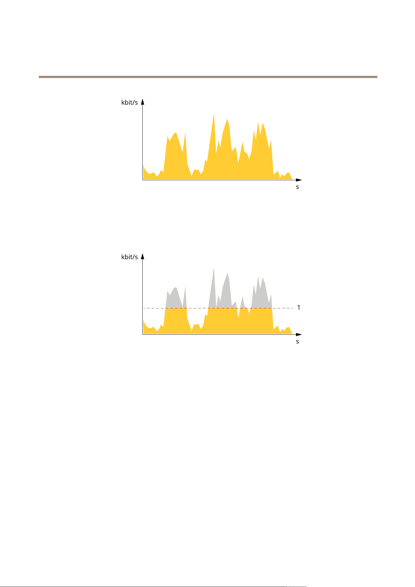
AXIS Q1686 - DLE Radar - Video Fusion Camera
Lear n mor e
Maximum bitrate (MBR)
Maximum bitrate lets you set a target bitrate to handle bitrate limitations in your system. Y ou might see a decline in image quality or
frame rate as the instantaneous bitrate is kept below the specied target bitrate. Y ou can choose to prioritize either image quality
or frame rate. W e recommend that you congure the target bitrate to a higher value than the expected bitrate. This gives you a
margin in case there is a high level of activity in the scene.
1
T arget bitrate
Average bitrate (ABR)
With average bitrate, the bitrate is automatically adjusted over a longer period of time. This is so you can meet the specied target
and provide the best video quality based on your available storage. Bitrate is higher in scenes with a lot of activity , compared to static
scenes. Y ou are more likely to get better image quality when in scenes with a lot of activity if you use the average bitrate option. Y ou
can dene the total storage required to store the video stream for a specied amount of time (retention time) when image quality is
adjusted to meet the specied target bitrate. Specify the average bitrate settings in one of the following ways:
• T o calculate the estimated storage need, set the target bitrate and the retention time.
• T o calculate the average bitrate, based on available storage and required retention time, use the target bitrate calculator .
7 1
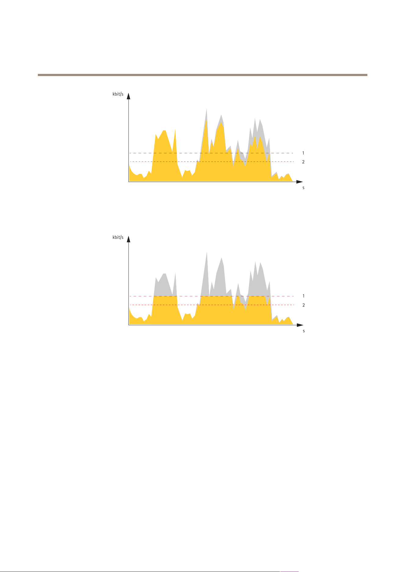
AXIS Q1686 - DLE Radar - Video Fusion Camera
Lear n mor e
kbit/s
s
1
2
1
T arget bitrate
2
Actual average bitrate
Y ou can also turn on maximum bitrate and specify a target bitrate within the average bitrate option.
kbit/s
s
1
2
1
T arget bitrate
2
Actual average bitrate
Cybersecurity
Axis Edge V ault
Axis Edge V ault provides a hardware - based cybersecurity platform that safeguards the Axis device. It offers features to guarantee the
device’s identity and integrity and to protect your sensitive information from unauthorized access. It builds on a strong foundation of
cryptographic computing modules (secure element and TPM) and SoC security (TEE and secure boot), combined with expertise in
edge device security .
Signed OS
Signed OS is implemented by the software vendor signing the AXIS OS image with a private key . When the signature is attached
to the operating system, the device will validate the software before installing it. If the device detects that the integrity of the
software is compromised, the AXIS OS upgrade will be rejected.
Secure boot
Secure boot is a boot process that consists of an unbroken chain of cryptographically validated software, starting in immutable
memory (boot ROM). Being based on the use of signed OS, secure boot ensures that a device can boot only with authorized software.
72

AXIS Q1686 - DLE Radar - Video Fusion Camera
Lear n mor e
Secure keystore
A tamper - protected environment for the protection of private keys and secure execution of cryptographic operations. It prevents
unauthorized access and malicious extraction in the event of a security breach. Depending on security requirements, an Axis device
can have either one or multiple hardware - based cryptographic computing modules, which provide a hardware - protected secure
keystore. Depending on security requirements, an Axis device can have either one or multiple hardware - based cryptographic
computing modules, like a TPM 2.0 (T rusted Platform Module) or a secure element, and/or a TEE (T rusted Execution Environment),
which provide a hardware - protected secure keystore. Furthermore, selected Axis products feature a FIPS 140 - 2 Level 2 - certied
secure keystore.
Axis device ID
Being able to verify the origin of the device is key to establishing trust in the device identity . During production, devices with
Axis Edge V ault are assigned a unique, factory - provisioned, and IEEE 80 2.1AR - compliant Axis device ID certicate. This works
like a passport to prove the origin of the device. The device ID is securely and permanently stored in the secure keystore as a
certicate signed by Axis root certicate. The device ID can be leveraged by the customer’s IT infrastructure for automated secure
device onboarding and secure device identication
Signed video
Signed video ensures that video evidence can be veried as untampered without proving the chain of custody of the video le. Each
camera uses its unique video signing key , which is securely stored in the secure keystore, to add a signature into the video stream.
When the video is played, the le player shows whether the video is intact. Signed video makes it possible to trace the video back to
the camera origin and veries that the video has not been tampered with after it left the camera.
Encrypted le system
The secure keystore prevents the malicious exltration of information and prevents conguration tampering by enforcing strong
encryption upon the le system. This ensures no data stored in the le system can be extracted or tampered with when the device is
not in use, unauthenticated access to the device is achieved and/or the Axis device is stolen. During the secure boot process, the
read - write lesystem is decrypted and can be mounted and used by the Axis device.
T o learn more about the cybersecurity features in Axis devices, go to axis.com/learning/white - papers and search for cybersecurity .
Axis security notication service
Axis provides a notication service with information about vulnerability and other security related matters for Axis devices. T o receive
notications, you can subscribe at axis.com/security - notication - service .
Vulnerability management
T o minimize customers' risk of exposure, Axis, as a Common Vulnerability and Exposures (CVE) numbering authority (CNA) , follows
industry standards to manage and respond to discovered vulnerabilities in our devices, software, and services. For more information
about Axis vulnerability management policy , how to report vulnerabilities, already disclosed vulnerabilities, and corresponding
security advisories, see axis.com/vulnerability - management .
Secure operation of Axis devices
Axis devices with factory default settings are pre - congured with secure default protection mechanisms. W e recommend using more
security conguration when installing the device. T o nd out more about Axis hardening guides and other cyber security related
documentation, go to axis.com/support/cybersecurity/resources .
73
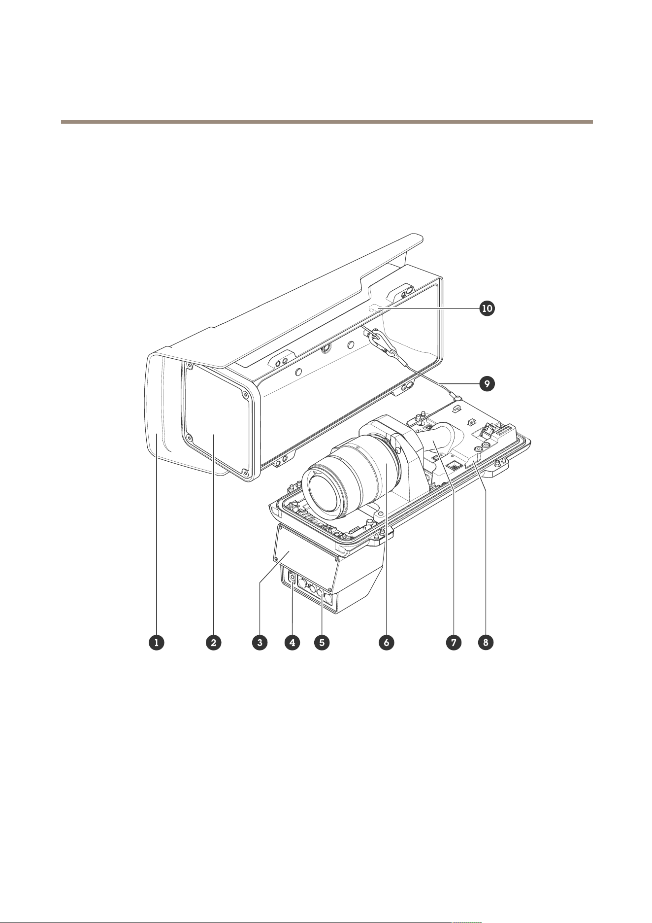
AXIS Q1686 - DLE Radar - Video Fusion Camera
Specifications
Specifications
Product overview
1
W eathershield
2
Window
3
Radar
4
Light sensor
5
IR illumination LED
6
Optical unit
7
Cable cover
8
Intrusion alarm sensor
9
Safety wire
1 0
Intrusion alarm magnet
74
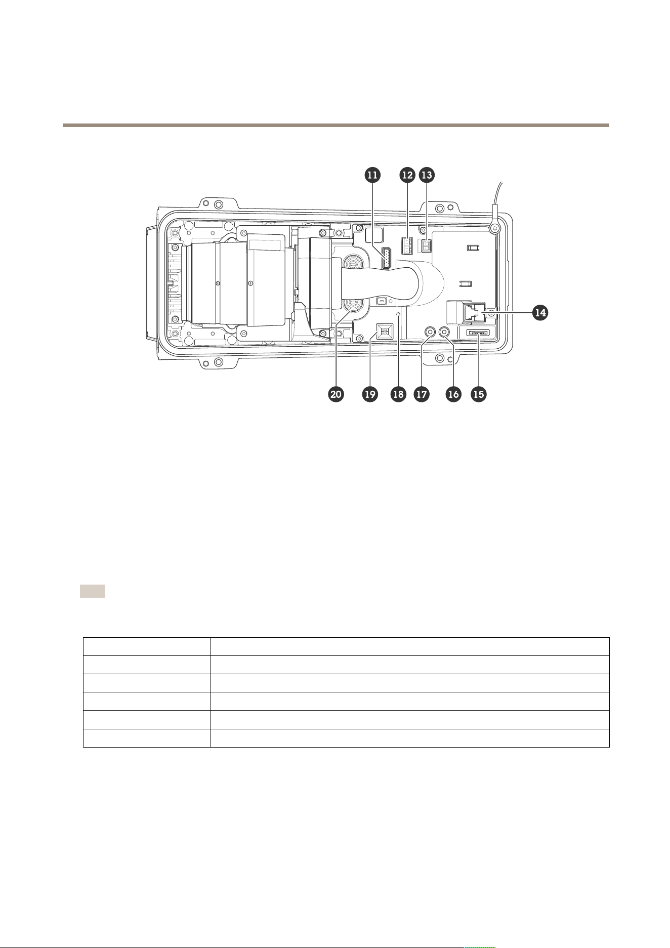
AXIS Q1686 - DLE Radar - Video Fusion Camera
Specifications
1 1
I/O connector
12
RS485/RS422 connector
13
P ower connector
14
Network connector (P oE)
15
microSD card slot
16
Audio out
17
Audio in
18
Status LED
19
Control button
20
Cable gasket M20 2x
LED indicators
Note
• The Status LED can be congured to ash while an event is active.
• The LEDs turn off when you close the casing.
Status LED
Indication
Unlit
Connection and normal operation.
Green Shows steady green for 1 0 seconds for normal operation after startup completed.
Amber
Steady during startup. Flashes during device software upgrade or reset to factory default.
Amber/Red Flashes amber/red if network connection is unavailable or lost.
Red Device software upgrade failure.
SD card slot
This device supports microSD/microSDHC/microSDXC cards.
For SD card recommendations, see axis.com .
75
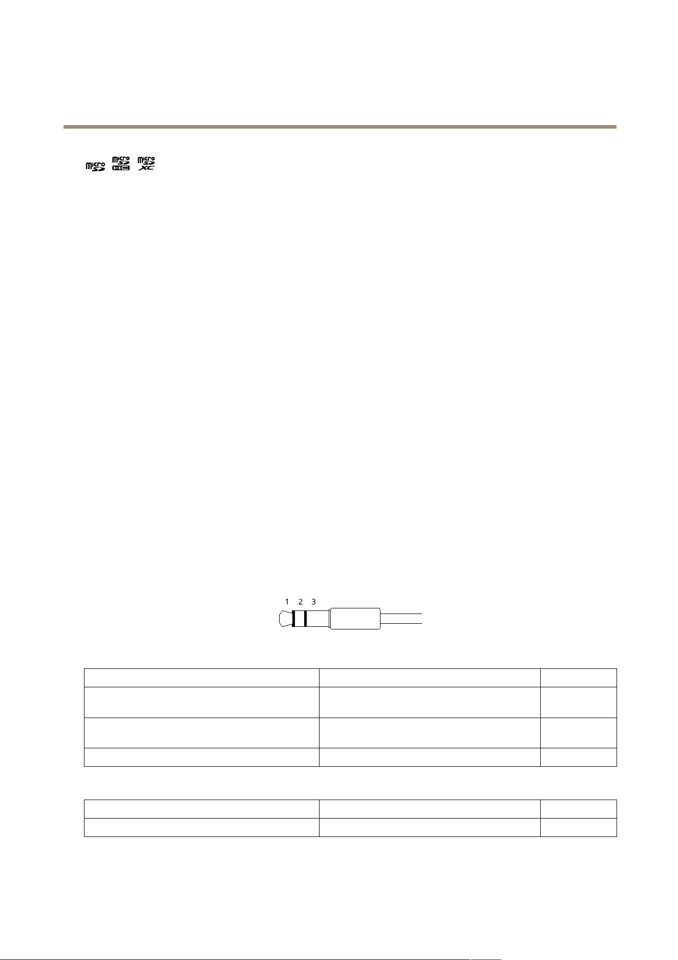
AXIS Q1686 - DLE Radar - Video Fusion Camera
Specifications
microSD, microSDHC, and microSDXC Logos are trademarks of SD - 3C LLC. microSD, microSDHC, microSDXC are
trademarks or registered trademarks of SD - 3C, LLC in the United States, other countries or both.
Buttons
Control button
The control button is used for:
• Resetting the product to factory default settings. See .
• Connecting to a one - click cloud connection (O3C) service over the internet. T o connect, press and hold the button
for about 3 seconds until the status LED ashes green.
Intrusion alarm switch
Use the intrusion alarm switch to get a notication when someone opens the device’s housing. Create a rule to make the device
perform an action when the switch is activated. See .
Connectors
Network connector
RJ45 Ethernet connector with P ower over Ethernet Plus (P oE+).
Audio connector
• Audio in – 3.5 mm input for a mono microphone, or a line - in mono signal (left channel is used from a stereo signal).
• Audio in – 3.5 mm input for a digital microphone, an analog mono microphone, or a line - in mono signal (left channel is
used from a stereo signal).
• Audio out – 3.5 mm output for audio (line level) that can be connected to a public address (P A) system or an active
speaker with a built - in amplier . A stereo connector must be used for audio out.
Audio input
1 Tip 2 Ring
3 Sleeve
Unbalanced microphone (with or without electret
power) or line - in
Electret power if selected
Ground
Balanced microphone (with or without phantom power)
or line - in, “hot” signal
Balanced microphone (with or without phantom
power) or line - in, “cold” signal
Ground
Digital signal Ring power if selected
Ground
Audio output
1 Tip 2 Ring
3 Sleeve
Channel 1, unbalanced line, mono Channel 1, unbalanced line, mono Ground
76
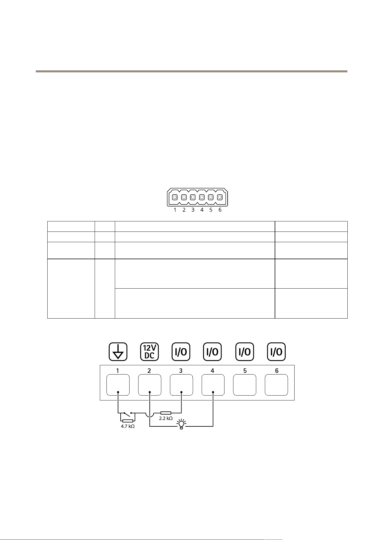
AXIS Q1686 - DLE Radar - Video Fusion Camera
Specifications
I/O connector
Use the I/O connector with external devices in combination with, for example, motion detection, event triggering, and alarm
notications. In addition to the 0 V DC reference point and power (12 V DC output), the I/O connector provides the interface to:
Digital input - For connecting devices that can toggle between an open and closed circuit, for example PIR sensors, door/window
contacts, and glass break detectors.
Supervised input - Enables possibility to detect tampering on a digital input.
Digital output - For connecting external devices such as relays and LEDs. Connected devices can be activated by the VAPIX®
Application Programming Interface, through an event or from the device’s web interface.
6 - pin terminal block
Function Pin Notes
Specications
DC ground
1
0 V DC
DC output
2
Can be used to power auxiliary equipment.
Note: This pin can only be used as power out.
12 V DC
Max load = 50 mA
Digital input or Supervised input – Connect to pin 1 to activate, or
leave oating (unconnected) to deactivate. T o use supervised input,
install end - of - line resistors. See connection diagram for information
about how to connect the resistors.
0 to max 30 V DCCongurable
(Input or Output)
3–6
Digital output – Internally connected to pin 1 (DC ground) when
active, and oating (unconnected) when inactive. If used with an
inductive load, e.g., a relay , connect a diode in parallel with the load,
to protect against voltage transients.
0 to max 30 V DC, open drain,
1 00 mA
Example:
1
DC ground
2
DC output 12 V, max 50 mA
3
I/O congured as supervised input
4
I/O congured as output
5
Congurable I/O
6
Congurable I/O
77
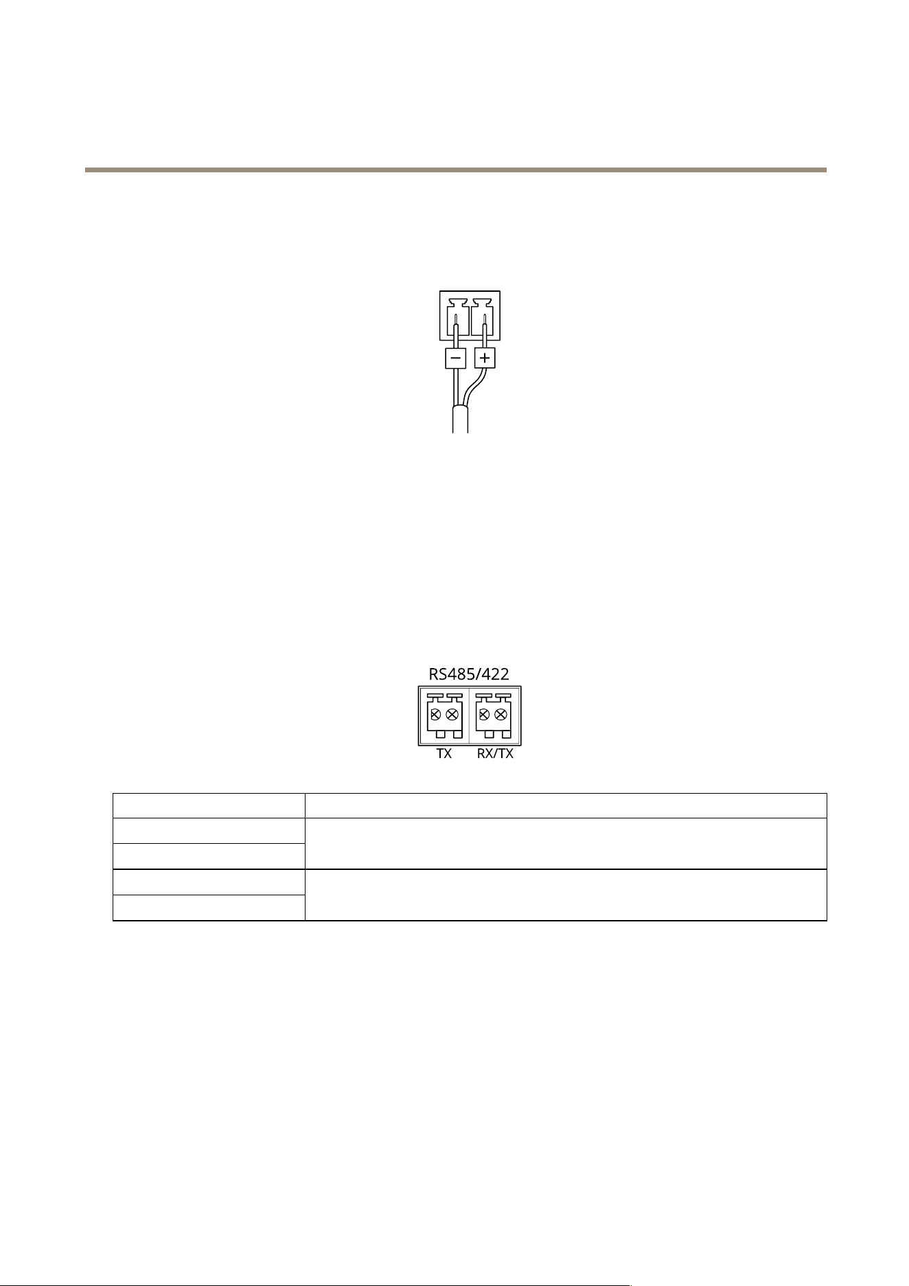
AXIS Q1686 - DLE Radar - Video Fusion Camera
Specifications
P ower connector
2 - pin terminal block for DC power input. Use a Safety Extra Low V oltage (SEL V) compliant limited power source (LPS) with either
a rated output power limited to ≤ 1 00 W or a rated output current limited to ≤ 5 A.
RS485/RS422 connector
T wo 2 - pin terminal blocks for RS485/RS422 serial interface.
The serial port can be congured to support:
• T wo - wire RS485 half duplex
• Four - wire RS485 full duplex
• T wo - wire RS422 simplex
• Four - wire RS422 full duplex point to point communication
Function Notes
RS485/RS422 TX(A)
RS485/RS422 TX(B)
TX pair for RS422 and 4 - wire RS485
RS485A alt RS485/422 RX(A)
RS485B alt RS485/422 RX(B)
RX pair for all modes (combined RX/TX for 2 - wire RS485)
78

AXIS Q1686 - DLE Radar - Video Fusion Camera
Clean your device
Clean your device
Y ou can clean your device with lukewarm water .
NO NO
NO
TICE TICE
TICE
• Harsh chemicals can damage the device. Don’t use chemicals such as window cleaner or acetone to clean your device.
• Avoid cleaning in direct sunlight or elevated temperatures, since this can cause stains.
1. Use a can of compressed air to remove dust and loose dirt from the device.
2. If necessary , clean the device with a soft microber cloth dampened with lukewarm water .
3. T o avoid stains, dry the device with a clean, nonabrasive cloth.
79

AXIS Q1686 - DLE Radar - Video Fusion Camera
T r oubleshooting
T r oubleshooting
Reset to factory default settings
W ARNING
P ossibly hazardous optical radiation is emitted from this product. It can be harmful to the eyes. Don’t stare at
the operating lamp.
Important
Reset to factory default should be used with caution. A reset to factory default resets all settings, including the IP address, to
the factory default values.
T o reset the product to the factory default settings:
1. Disconnect power from the product.
2. Press and hold the control button while reconnecting power . See .
3. K eep the control button pressed for 15–30 seconds until the status LED indicator ashes amber .
4. Release the control button. The process is complete when the status LED indicator turns green. The product has been reset
to the factory default settings. If no DHCP server is available on the network, the default IP address is 192.168.0.90 .
5. Use the installation and management software tools to assign an IP address, set the password, and access the device.
The installation and management software tools are available from the support pages on axis.com/support .
Y ou can also reset parameters to factory default through the device’s web interface. Go to Maintenance > Factory default and
click Default .
AXIS OS options
Axis offers device software management according to either the active track or the long - term support (L TS) tracks. Being on the
active track means continuously getting access to all the latest product features, while the L TS tracks provide a xed platform with
periodic releases focused mainly on bug xes and security updates.
Using AXIS OS from the active track is recommended if you want to access the newest features, or if you use Axis end - to - end system
offerings. The L TS tracks are recommended if you use third - party integrations, which are not continuously validated against the latest
active track. With L TS, the products can maintain cybersecurity without introducing any signicant functional changes or affecting
any existing integrations. For more detailed information about Axis device software strategy , go to axis.com/support/device - software .
Check the current AXIS OS version
AXIS OS determines the functionality of our devices. When you troubleshoot a problem, we recommend that you to start by checking
the current AXIS OS version. The latest version might contain a correction that xes your particular problem.
T o check the current AXIS OS version:
1. Go to the device’s web interface > Status .
2. Under Device info , see the AXIS OS version.
80

AXIS Q1686 - DLE Radar - Video Fusion Camera
T r oubleshooting
Upgrade AXIS OS
Important
• Precongured and customized settings are saved when you upgrade the device software (provided that the features are
available in the new AXIS OS) although this is not guaranteed by Axis Communications AB .
• Make sure the device remains connected to the power source throughout the upgrade process.
Note
When you upgrade the device with the latest AXIS OS version in the active track, the product receives the latest functionality
available. Always read the upgrade instructions and release notes available with each new release before you upgrade. T o
nd the latest AXIS OS version and the release notes, go to axis.com/support/device - software .
1. Download the AXIS OS le to your computer , available free of charge at axis.com/support/device - software .
2. Log in to the device as an administrator .
3. Go to Maintenance > AXIS OS upgrade and click Upgrade .
When the upgrade has nished, the product restarts automatically .
T echnical issues , clues , and solutions
If you can’t nd what you’re looking for here, try the troubleshooting section at axis.com/support .
Problems upgrading AXIS OS
AXIS OS upgrade failure
If the upgrade fails, the device reloads the previous version. The most common reason is that the
wrong AXIS OS le has been uploaded. Check that the name of the AXIS OS le corresponds to
your device and try again.
Problems after AXIS OS
upgrade
If you experience problems after the upgrade, roll back to the previously installed version from
the Maintenance page.
Problems setting the IP address
The device is located on a
different subnet
If the IP address intended for the device and the IP address of the computer used to access the
device are located on different subnets, you cannot set the IP address. Contact your network
administrator to obtain an IP address.
The IP address is being used
by another device
Disconnect the Axis device from the network. Run the ping command (in a Command/DOS window ,
type ping and the IP address of the device):
• If you receive: Reply from <IP address>: bytes=32; time=10...
this means that the IP address may already be in use by another device on the network.
Obtain a new IP address from the network administrator and reinstall the device.
• If you receive: Request timed out , this means that the IP address is available
for use with the Axis device. Check all cabling and reinstall the device.
P ossible IP address conict
with another device on the
same subnet
The static IP address in the Axis device is used before the DHCP server sets a dynamic address.
This means that if the same default static IP address is also used by another device, there may
be problems accessing the device.
The device can’t be accessed from a browser
Can’t log in
When HTTPS is enabled, ensure that the correct protocol (HTTP or HTTPS) is used when attempting
to log in. Y ou may need to manually type http or https in the browser’s address eld.If the
password for the root account is lost, the device must be reset to the factory default settings. See .
8 1

AXIS Q1686 - DLE Radar - Video Fusion Camera
T r oubleshooting
The IP address has been
changed by DHCP
IP addresses obtained from a DHCP server are dynamic and may change. If the IP address has been
changed, use AXIS IP Utility or AXIS Device Manager to locate the device on the network. Identify
the device using its model or serial number , or by the DNS name (if the name has been congured).If
required, a static IP address can be assigned manually . For instructions, go to axis.com/support .
Certicate error when using
IEEE 80 2.1X
For authentication to work properly , the date and time settings in the Axis device must be
synchronized with an NTP server . Go to System > Date and time .
The device is accessible locally but not externally
T o access the device externally , we recommend you to use one of the following applications for Windows
®
:
• AXIS Camera Station 5: 30 - day trial version free of charge, ideal for small to mid - size systems.
• AXIS Camera Station Pro: 90 - day trial version free of charge, ideal for small to mid - size systems.
For instructions and download, go to axis.com/vms .
Can’t connect over port 8883 with MQTT over SSL
The rewall blocks trafc
using port 8883 as it’s
deemed insecure.
In some cases the server/broker might not provide a specic port for MQTT communication. It may
still be possible to use MQTT over a port normally used for HTTP/HTTPS trafc.
• If the server/broker supports W ebSocket/W ebSocket Secure (WS/WSS), typically on
port 443, use this protocol instead. Check with the server/broker provider to see if
WS/WSS is supported and which port and basepath to use.
• If the server/broker supports ALPN, the use of MQTT can be negotiated over an open
port, such as 443. Check with your server/broker provider to see if ALPN is supported
and which ALPN protocol and port to use.
Problems with overlays when using AXIS License Plate V erier
The license plate overlay is
not available in the device’s
onscreen controls
If the license plate overlay isn’t available in the device’s onscreen controls after you have installed
AXIS License Plate V erier , try to restart the device.Go to the Maintenance page and click Restart .
Speed is missing in the
license plate overlay in the
device’s onscreen controls
If the speed is missing in the license plate overlay after you have installed AXIS License Plate
V erier , make sure the mounting height of the device is set correctly in the device’s web interface.T o
set the installation height in the device, go to Radar > Settings > General > Mounting height .
P erformance considerations
The following factors are the most important to consider:
• Heavy network utilization due to poor infrastructure affects the bandwidth.
Contact support
If you need more help, go to axis.com/support .
82

User manual V er . M2.2
AXIS Q1686 - DLE Radar - Video Fusion Camera
Date: July 20 24
© Axis Communications AB, 20 24
P art no. T1 0 20 2497