Loading ...
Loading ...
Loading ...
13
MAINTENANCE
WARNING:
To avoid serious personal injury, always stop
the engine and allow it to cool before cleaning or maintaining
the unit. Never perform cleaning or maintenance while the
unit is running. Disconnect the spark plug wire to prevent
the unit from starting accidentally.
WARNING:
Wear protective clothing and observe all
safety instructions to prevent serious personal injury.
MAINTENANCE SCHEDULE
Perform these required maintenance procedures at the frequency
stated in the table. These procedures should also be a part of any
seasonal tune-up.
NOTE: Some maintenance procedures may require special tools or
skills. If you are unsure about these procedures, take the unit to
an authorized service dealer. Call 1-888-331-4569 for more
information.
NOTE: Maintenance, replacement, or repair of the emission control
devices and system may be performed by an authorized service
dealer. Call 1-888-331-4569 for more information.
NOTE: Please read the California/EPA statement that came with the
unit for a complete listing of terms and coverage for the
emissions control devices, such as the spark arrestor, muffler,
carburetor, etc.
FREQUENCY MAINTENANCE REQUIRED
Every 10 hours • Clean and re-oil the air filter. Refer to
Maintaining the Air Filter.
After the first
10 hours and
at 38 hours
• Change the oil. Refer to Changing the Oil.
• Have the rocker arm clearance checked by
an authorized service dealer.
• Check the spark plug condition and gap.
Refer to Maintaining the Spark Plug.
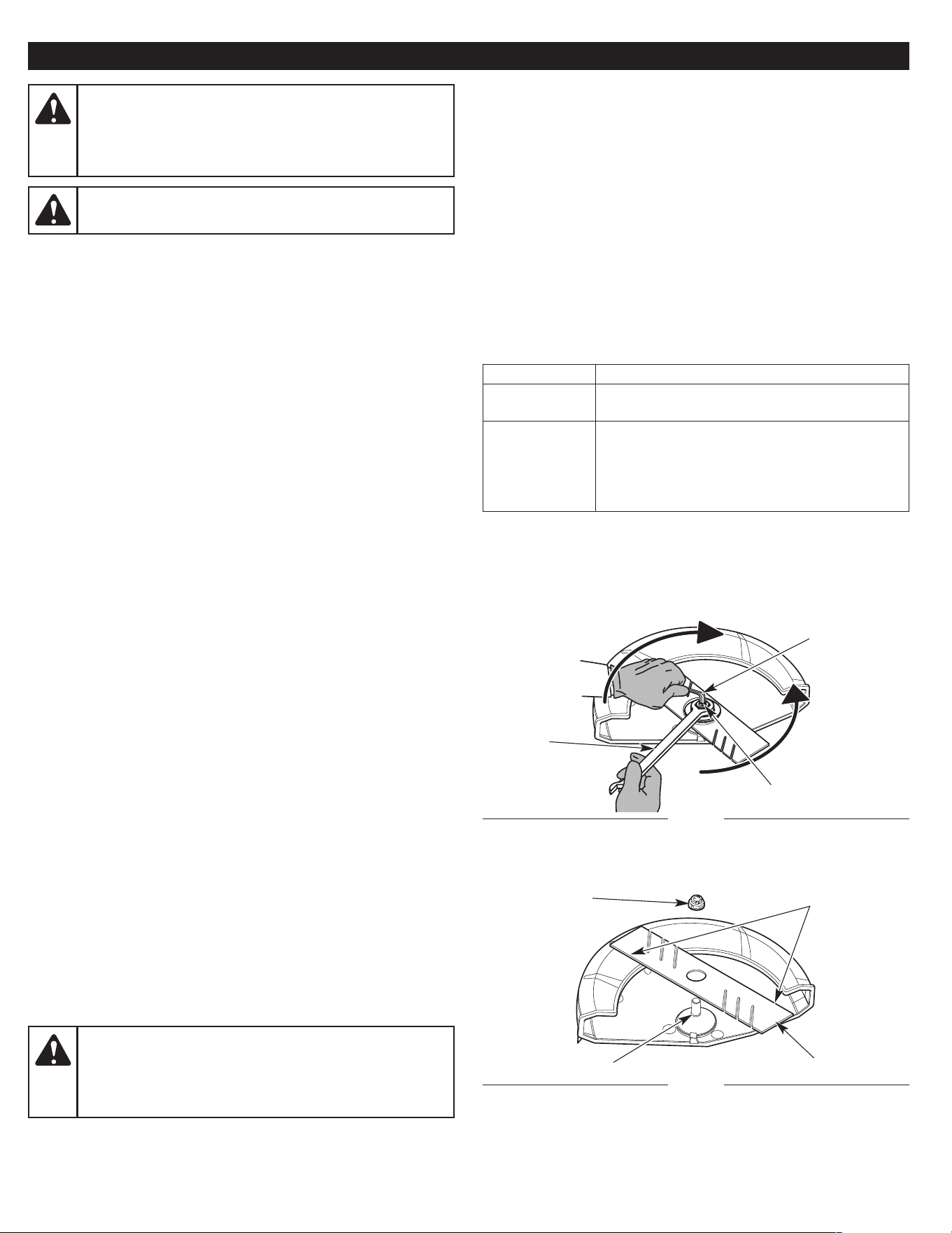
REPLACING THE EDGER BLADE
Removing the Edger Blade
1. Place a 15/16 in. wrench over the lock nut (Fig. 13).
2. Insert a 5/16 in. Allen wrench into the spindle hole (Fig. 13).
3. While hold ing the Allen wrench in place, loosen the lock nut by
turning it counterclock wise with the wrench (Fig. 13).
4. Remove the Allen wrench, wrench, lock nut and edger blade
(Fig. 14). Keep the lock nut for installing the new edger blade.
Installing the Edger Blade
1. Install the new edger blade and lock nut onto the output shaft
(Fig. 14). Make sure the blade edges are facing the correct
direction (Fig. 14). The unit will not function properly if the edger
blade is facing the wrong direction.
2. Place the wrench over the lock nut (Fig. 13).
3. Insert the Allen wrench into the spindle hole (Fig. 13).
4. While hold ing the Allen wrench in place, tighten the lock nut by
turning it clock wise with the wrench (Fig. 13). Make sure that the
edger blade stays flat and centered against the output shaft
while tightening the lock nut. Tighten the lock nut until the edger
blade is firmly secure.
5. Remove the wrench and Allen wrench.
Fig. 13
Spindle Hole
Allen Wrench
Wrench
Fig. 14
Lock Nut
Edger Blade
Blade Edges
Output Shaft
Loosen
Tighten
WARNING:
Make sure the blade is flat against the
output shaft bushing after the lock nut is tightened. If the
blade is off-cen ter, the unit will be dam aged by vibration,
and the blade may fly off, which can cause serious
personal in ju ry.
Loading ...
Loading ...
Loading ...