Loading ...
3. Stabilizer Installation – Assemble the stabilizer on the specied
position of the riser (as shown in the Picture 4)
BOW ADJUSTMENT
1. Peak Draw Weight Adjustments (as shown on Picture 5)
This bow has roughly 30lbs to 70lbs peak weight adjustment range.
Adjust the draw weight by screwing the bolts on the limbs and riser,
turn the bolts on the draw weight and counter-clockwise to decrease.
PAY ATTENTION to adjust the two bolts equally. The bow you get is with
40-45lb draw weight, which can be adjusted with steps above.
Watch out: Never over tighten or loosen bolts.
2. Draw Length Adjustment
This bow has 12 gears adjustment range (as shown in the picture 6)
There are 12 two-socket ay head cap screw on the modular cam. You
can adjust draw length freely according to your stature and arm span.
When you adjust the draw length, rst loosen the screw in the middle
of the cam, press cable by the hand to remove it. Second move the cam
to the correct length hole and then tighten the screw and loosen the
cable..
User Manual
www.PyleUSA.com
www.PyleUSA.com
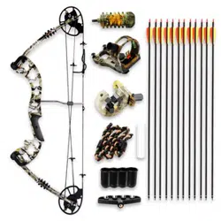
COMPOUND BOW PARTS DIAGRAM
FEATURES
1. High performance dual CAM system.
2. Adjustable draw weight and draw length.
3. Application of rubber damper and string silencer makes the shooting more stable, and makes shooting
less noisy.
BOW ASSEMBLY
1. Arrow Rest Installation – Install the arrow rest on the riser of the bow
(as shown on Picture 1), Archers adjust the position of the arrow rest
according to the length of arrow used. Generally speaking, the distance
between the arrowhead and arrow rest is ove 4cm after bow drawing.
(Watch out the gap arrow rest upwards).
2. Sight Installation – Install the sight on the bow riser with the screws
provided (as shown on Picture 2), the screw can be on both hole A and
hole B. If assemble on hole B, shooting range will be 5m or so shorter
than hole A.
• Install the blue night light on the sight (as shown on Picture 3),
which can be turned on when light is poor.
Rubber Stabilizer
Rubber Stabilizer
Riser
Arrow Rest
Cable Guard
Cables
Limb Base
Limb
Rubber Damper
Top Cam
Rubber Stabilizer
D-LoopString
String Silencer
Buttom Cam
Five Pin Sight
SCREW NO. 1 2 3 4 5 6 7 8 9 10 11 12
DRAW
LENGTH
23.5” 24.1” 24.7” 25.4” 26” 26.7” 27.4” 28” 28.6” 29.3” 29.9” 30.5”