Page 1
INSTRUCTION MANUAL
WASHER DRYER STAND
Thank you for choosing BLACK+DECKER!
PLEASE READ BEFORE RETURNING THIS PRODUCT FOR ANY
REASON.
If you have a question or experience a problem with your BLACK+DECKER
purchase, go to www.blackanddecker.com/instantanswers
If you can’t find the answer or do not have access to the Internet, call
844-299-0879 from 10:30 a.m. to 6:30 p.m. EST Mon.-Fri. to speak with an
agent. Please have the catalog number available when you call.
SAVE THIS MANUAL FOR FUTURE REFERENCE.
CATALOG NUMBER
BWDS

Page 2
Thank you for purchasing our
BLACK+DECKER product. This
easy-to-use manual will guide you
in getting the best use of your
washer dryer stand.
Remember to record the model and
serial numbers. They are on a label
on the rear.
Staple your receipt to your manual. You will need it to obtain warranty service.
Model number
Serial number
Date of purchase
SAFETY INFORMATION
Important Safety Instructions ..............................................................................................................................................3
SET UP & USE
Parts List .....................................................................................................................................................................................4-7
Assembly Instructions ........................................................................................................................................8-21
Product Dimensions ............................................................................................................................................... 22
CLEANING & CARE .............................................................................................................................................23
TROUBLESHOOTING & WARRANTY
Important ..................................................................................................................................................................23
Limited Warranty .................................................................................................................................................................... 24
CONTENTS
PRODUCT REGISTRATION
Page 3
READ ALL INSTRUCTIONS BEFORE USE.
WARNING:
• Maximum Weight for Dryer Rack 60 lbs. Do not exceed maximum weight limit.
• This washer dryer stand must be anchored to a wall using anti-tip brackets to
avoid tipping.
RISK OF PERSONAL INJURY OR DEATH. THE STAND MUST BE SECURED TO
RIGID FRAMING MEMBER OF ADJACENT WALL BEFORE USING.
• Some assembly parts may cause choking. Keep away from children.
• Do not lean on, or allow children to play or climb on the washer dryer stand. Do not
allow children to hang from the door of the dryer when seated on the top of the
washer dryer stand because this could cause tipping.
SAVE THESE INSTRUCTIONS
HOUSEHOLD USE ONLY
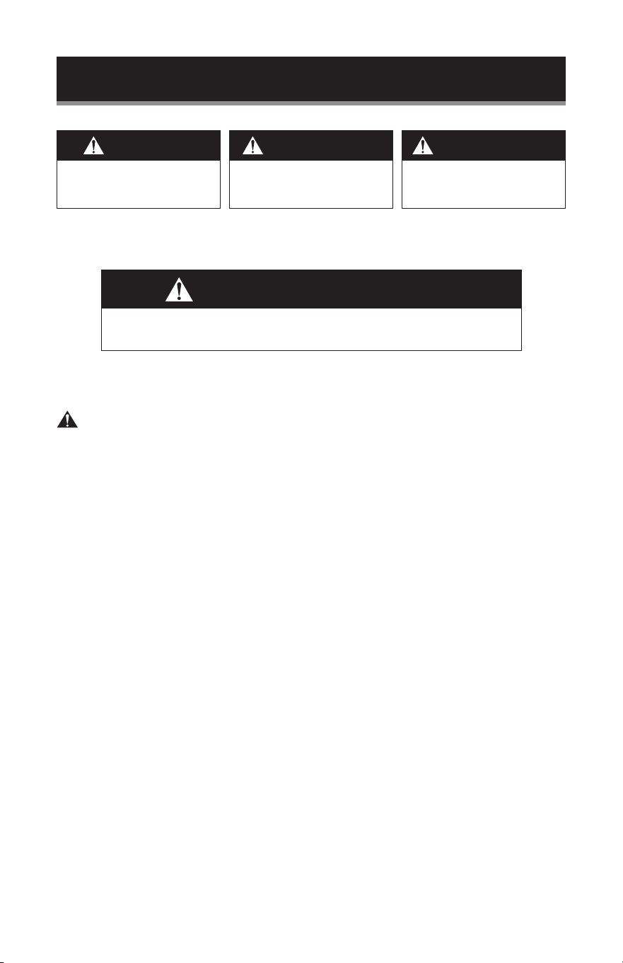
WARNING
When using the washer dryer stand , basic safety precautions
should be followed, including the following:
DANGER
DANGER - Immediate hazards
that WILL result in severe
personal injury or death
WARNING
WARNING - Hazards or unsafe
practices that COULD result in
severe personal injury or death
CAUTION
CAUTION - Hazards or unsafe
practices that COULD result in
minor personal injury
IMPORTANT SAFETY INSTRUCTIONS
SAFETY INFORMATION
Page 4
SET UP & USE
Tools Required: Screwdriver and Drill (not included)
NOTE:
20S = 4 short 20mm screws.
Used for installing the front base support to the side base rails. Must be inserted so
that the screw head is in on the interior side front base.
20SD = 4 short 20mm large diameter screws. Used for 3T dryer support bars. Must
be inserted from the top of the dryer supports.
25S = 6 short 25mm screws
Used for installing the dryer support to the upper vertical poles and the side support
rails to the lower vertical poles. Must be inserted so that the screw head is in on the
exterior of the unit.
35M = 12 medium 35mm screws. Connects diagonal support rails, side rails and
connecting rails to the vertical poles and installs the vertical poles to the base. Must
be inserted so that the screw head is in on the exterior of the unit.
40LD = 4 long 40mm screws. Only used when installing the BCED15 Dryer (sold
separately). Used for connecting the BCED15 dryer to the dryer support bars. Must
be inserted though the bottom of the dryer support bar. These screws will not be
necessary for larger size dryer connection.
45L = 6 long 45mm screws. Used to connect vertical poles to reinforcing bars. Must
be inserted through vertical rail rst then tightened into Reinforcing Bars.
NOTE: It is important to use the correct screw and insert in the location as directed in
the instructions.
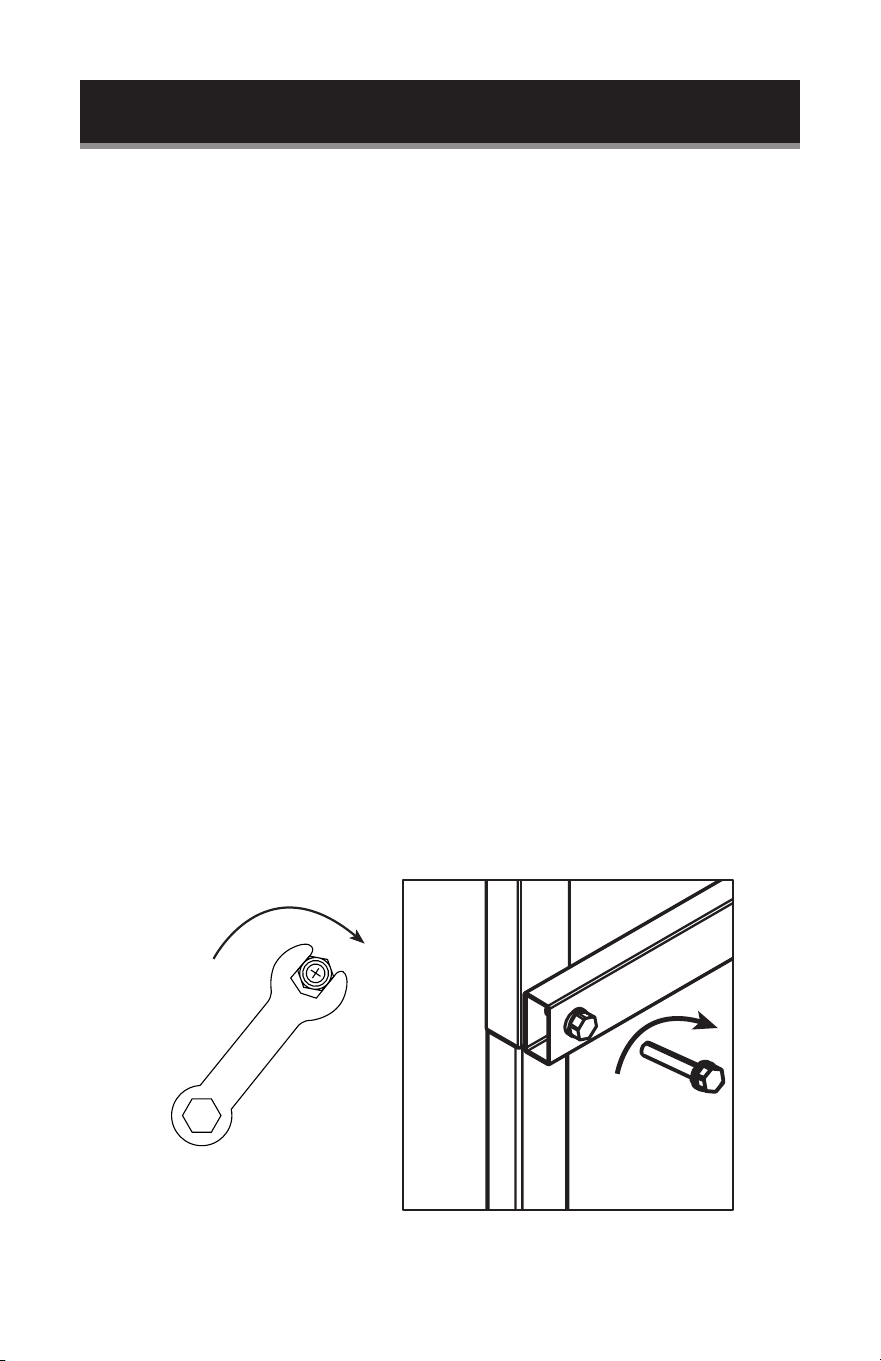
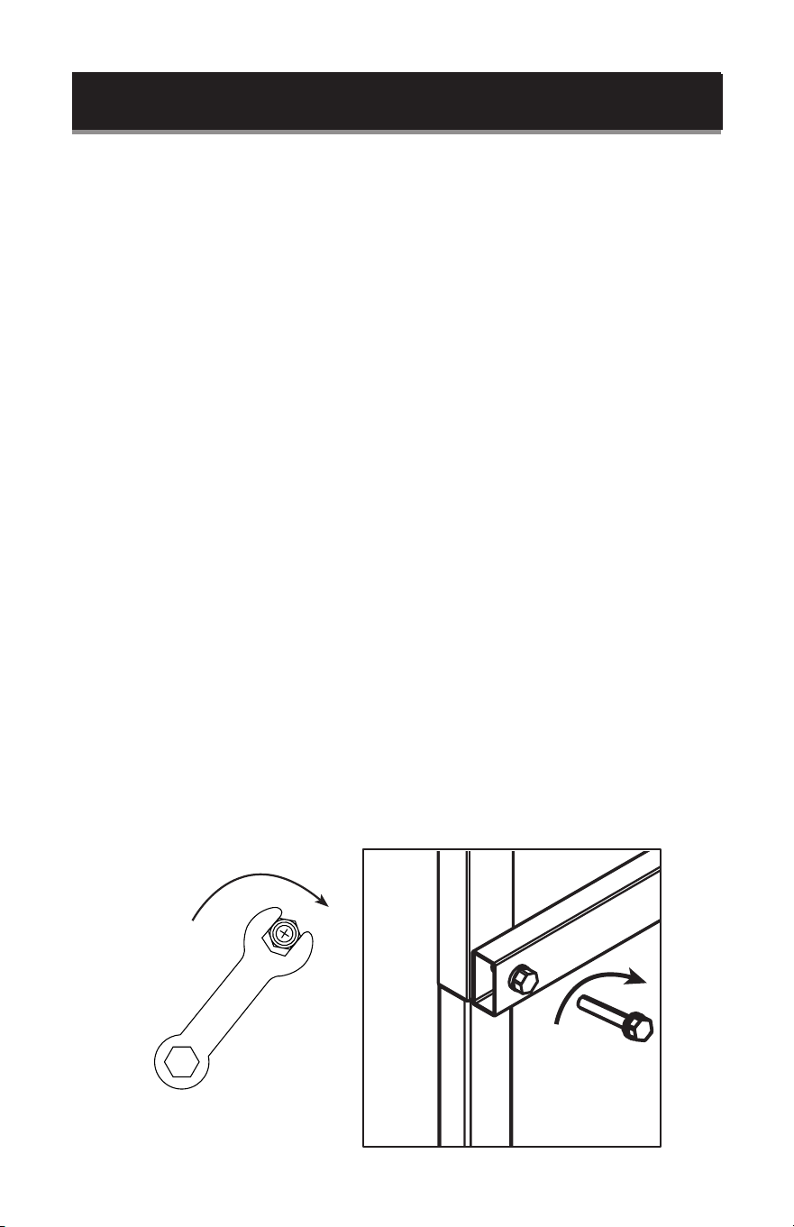
To install the screws, use the included wrench or screwdriver (not included). Insert
and turn to the right until the entire threaded part of the screw is fully inserted.

Page 5
SET UP & USE
ID DESCRIPTION QUANTITY
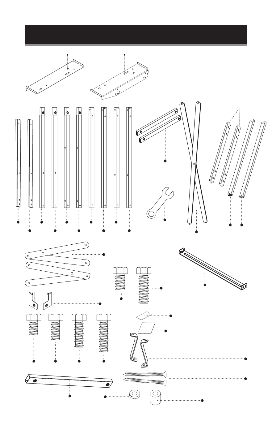
1F FRONT BASE 1
1B BACK BASE 1
2B DIAGONAL SUPPORT RAIL 1
1R RIGHT BASE 1
2R LOWER RIGHT FRONT VERTICAL POLE 1
3R LOWER RIGHT BACK VERTICAL POLE 1
4R UPPER RIGHT FRONT VERTICAL POLE 1
5R UPPER RIGHT BACK VERTICAL POLE 1
8R RIGHT DRYER SUPPORT 1
1L LEFT BASE 1
2L LOWER LEFT FRONT VERTICAL POLE 1
3L LOWER LEFT BACK VERTICAL POLE 1
4L UPPER LEFT FRONT VERTICAL POLE 1
5L UPPER LEFT BACK VERTICAL POLE 1
8L LEFT DRYER SUPPORT 1
6 SIDE SUPPORT RAIL 2
7 CONNECTING RAIL 2
1T REINFORCING BAR (caps on the end) 1
2T REINFORCING BAR 1
3T DRYER SUPPORT BAR (FOR USE WITH MODEL BCED15) 2
ANTI-TIP BRACKET 2
CORNER SUPPORT 2
NON-SLIP PADS - SMALL (FOR BOTTOM OF THE STAND) 6
NON-SLIP PADS - LARGE (FOR BOTTOM OF THE DRYER) 4
RUBBER SPACER (USED TO ATTACH SMALL CAPACITY BCED15 DRYER) 4
WASHER(USED TO ATTACH SMALL CAPACITY BCED15 DRYER) 4
20S 20MM SHORT SCREW 4
20SD 20MM SHORT LARGE DIAMETER SCREW (FOR T3 DRYER SUPPORT BAR) 4
25S 25MM SHORT SCREW 6
35M 35MM MEDIUM SCREW 12
40LD 40MM LONG SCREW (USED TO ATTACH SMALL CAPACITY BCED15 DRYER) 4
45L 45MM LONG SCREW 6
LAG TYPE SCREWS (TO SECURE DRYER STAND TO THE WALL ) 2
WRENCH 1

Page 6
SET UP & USE
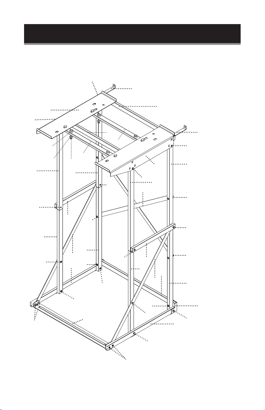
PARTS & FEATURES
Anti-tip Bracket
25S
25S
25S
25S
Anti-tip Bracket
8R
8L
3T
40LD
3T
1T
2T
2B
1B
6
6
7
7
25S
25S
4R
4L
2L
3L
35M
35M
35M
35M
35M
35M
35M
35M
35M
35M
35M
5L
5R
3R
Corner support
1R
45L
45L
1L
1F
2R
20S
20S
Rubber Spacers
Washers
Page 7
SET UP & USE
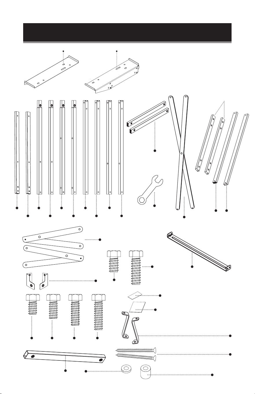
7
2B
6
Anti-tip Bracket
Lag Type Screws
1T 2T
3T
20S
20SD
40LD
25S 35M 45L
Non-slip Pads 1.6”x.6”
Large Non-slip Pads 1.97”x1.97”
1F
8L 8R
Corner Supports
1B
Washers
Rubber Spacers
Wrench
1R 2R 3R 4R 5R
1L 2L 3L 4L 5L
Page 8
SET UP & USE
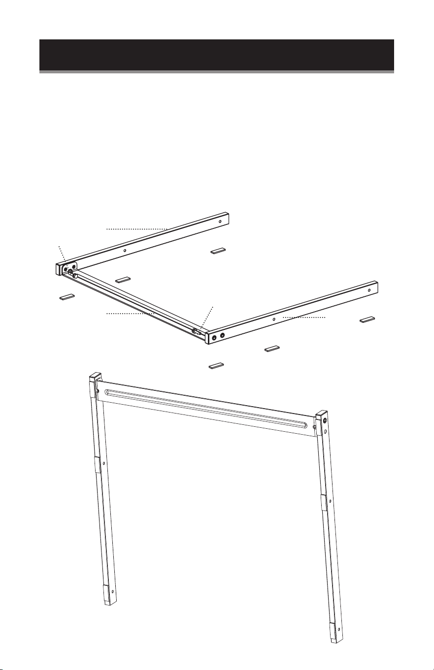
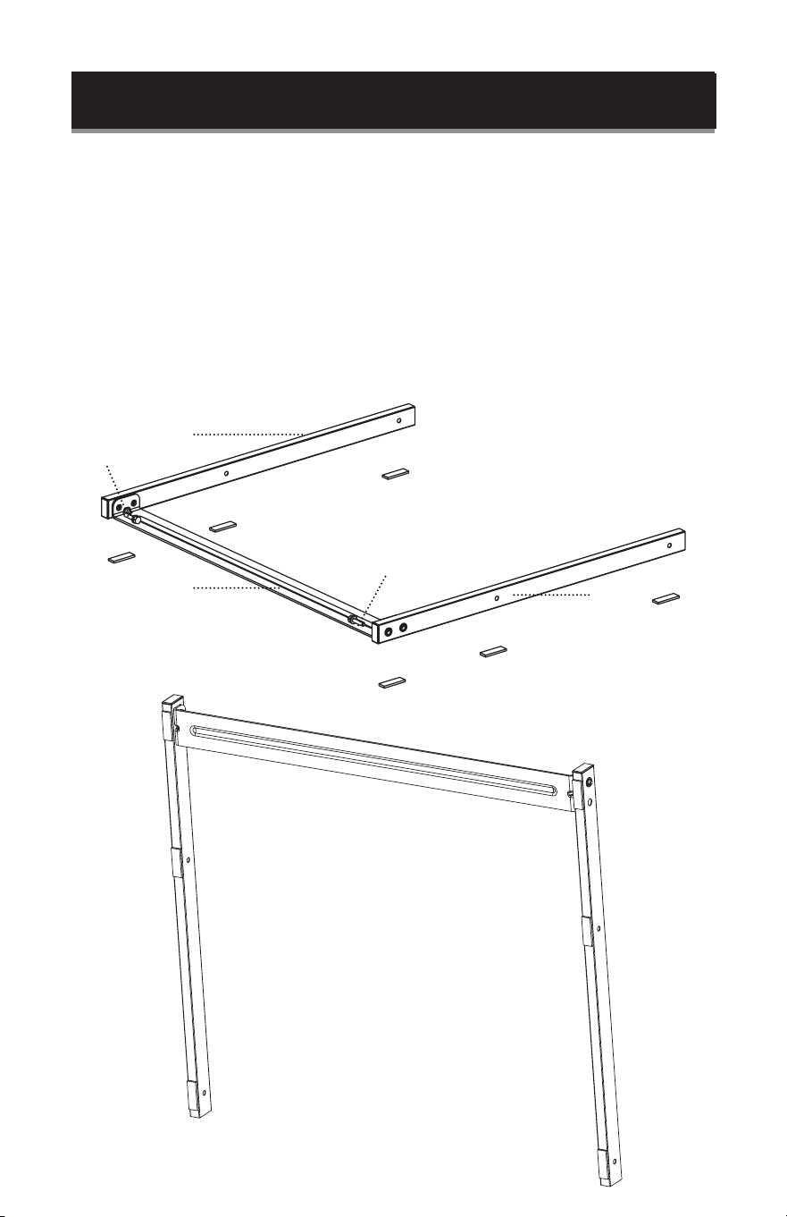
Line up the 2 holes of 1R (RIGHT BASE SUPPORT) with the right side of 1F (FRONT
BASE). Insert 20S (20mm SHORT SCREW) through the screw hole on the exterior
side of 1F (FRONT BASE) until firmly secured into 1R (RIGHT BASE).
Line up the 2 holes of 1L (LEFT BASE) with the left side of 1F (FRONT BASE). Insert
20S (20mm SHORT SCREW) through the screw hole on the exterior side of 1F
(FRONT BASE) until firmly secured into 1L (LEFT BASE)
Remove the backing from the (6) NON-SLIP PADS SMALL (1.6”x.6”).
Place the sticky side on the base of the unit as shown in the diagram.
1L
1R
1F
20S
20S
SMALL ADHESIVE
NON-SLIP PADS x6
#1
#2
#3
#4
#5
#6

Page 9
SET UP & USE
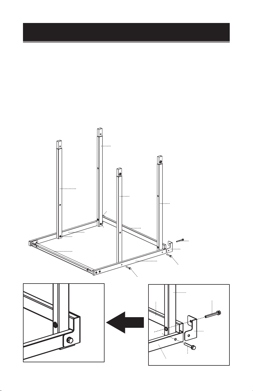
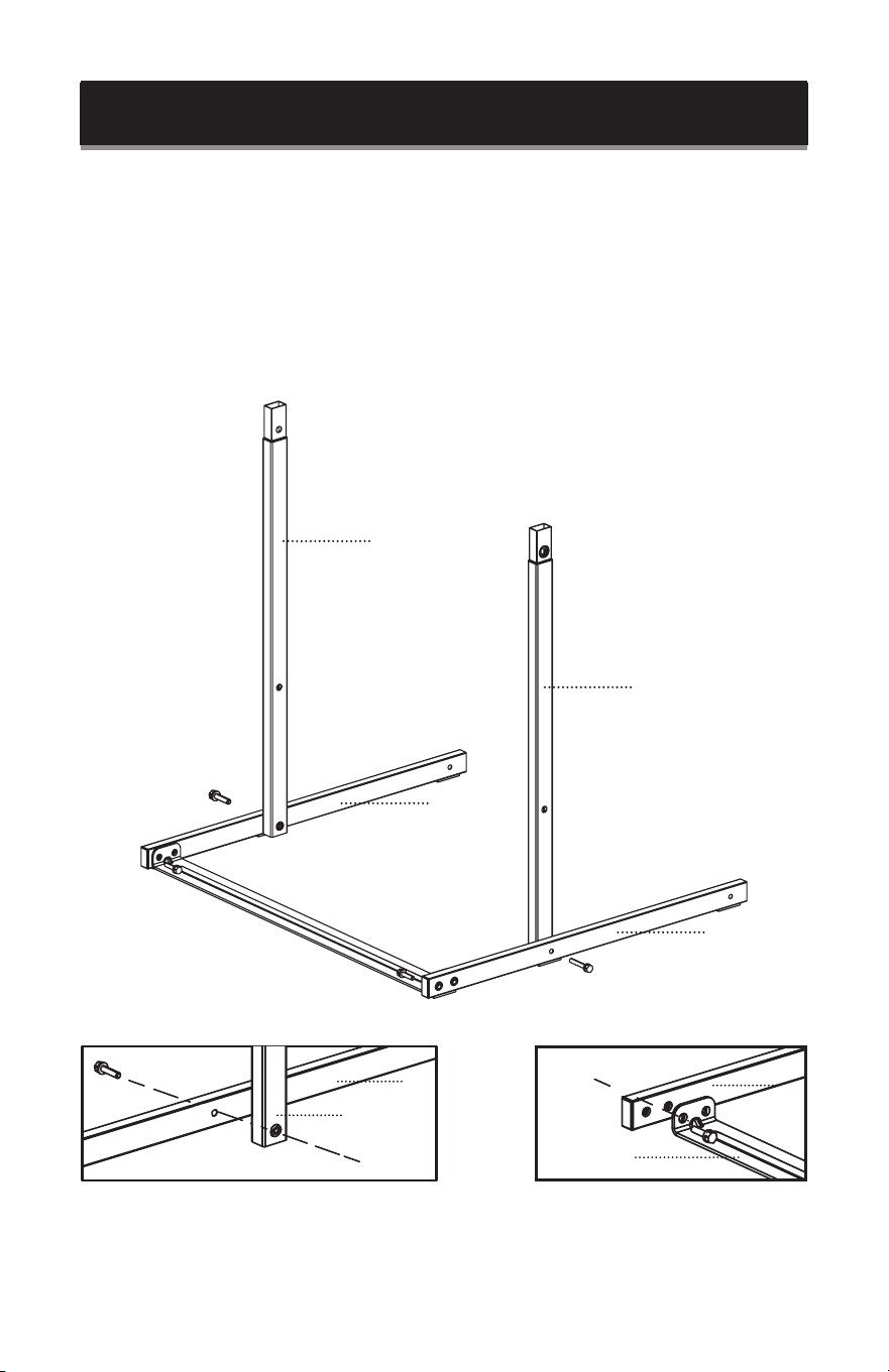
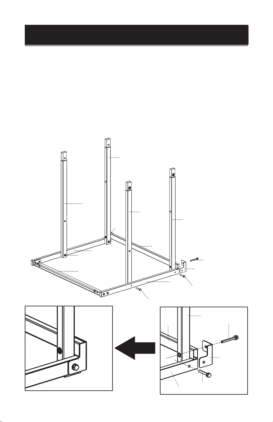
Using the diagram below as reference to position the poles, INSERT 2R (LOWER
RIGHT FRONT VERTICAL POLE) into 1R (RIGHT BASE). The base of the poles should
be positioned between the 1R (RIGHT BASE) slots and aligned with the holes. Use
35M (35mm MEDIUM SCREWS) to secure. It should be inserted from the outside of
R1 (RIGHT BASE) and inserted fully through the hole of the pole to secure.
NOTE: Follow the same steps to insert 2L (LOWER LEFT FRONT VERTICAL POLE)
into 1L (LEFT BASE) on the left side.
2L
1L
1L
1L
1F
2L
1R
2R
Page 10
SET UP & USE
3L
3R
45L
1B
45L
CORNER SUPPORT
35M
35M
35M
35M
2R
1L
1F
2L
1R
Insert 3R (LOWER RIGHT BACK VERTICAL POLE) into the rear slot of 1R (RIGHT
BASE).
Align with the hole of 1B (BACK BASE) and the CORNER SUPPORT. Insert 45L
(45mm LONG SCREW) all the way through the hole of the (CORNER SUPPORT), 1B
(BACK BASE) and then 3R (LOWER RIGHT BACK VERTICAL POLE).
Add 35M (35mm MEDIUM SCREW) through the remaining hole of the (CORNER
SUPPORT) and insert into 3R (LOWER RIGHT BACK VERTICAL POLE).
NOTE: Follow the same steps to assemble the left side.
1B
3R
CORNER
SUPPORT
1R
35M
45L

Page 11
SET UP & USE
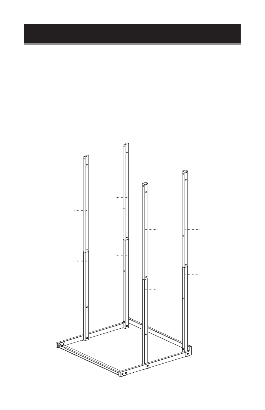
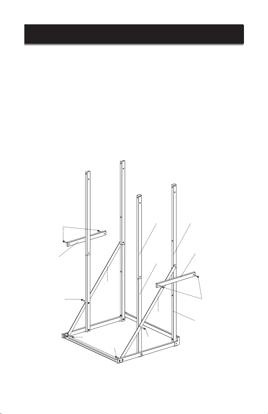
Insert 4R (UPPER RIGHT FRONT VERTICAL POLE) into 2R (LOWER RIGHT FRONT
VERTICAL POLE).
Insert 5R (UPPER RIGHT BACK VERTICAL POLE) into 3R (LOWER RIGHT BACK
VERTICAL POLE).
Insert 4L (UPPER LEFT FRONT VERTICAL POLE) into 2L (LOWER LEFT FRONT
VERTICAL POLE).
Insert 5L (UPPER LEFT BACK VERTICAL POLE) into 3L (LOWER LEFT BACK
VERTICAL POLE).
4L
5L
4R 5R
3R
2R
3L
2L

Page 12
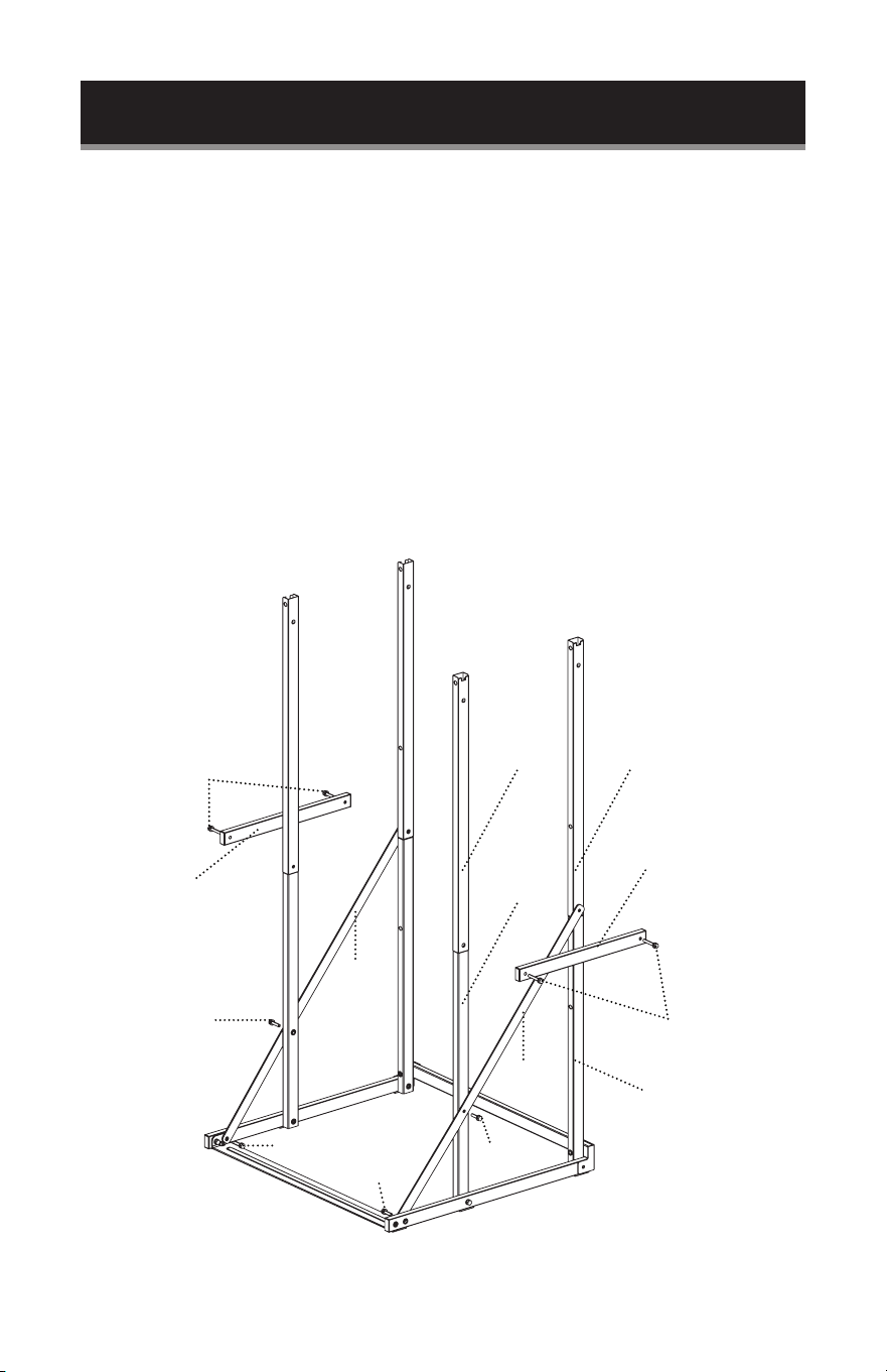
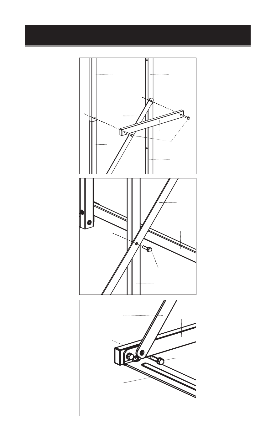
SET UP & USE
Line up the hole of one side of a 6 (SUPPORT RAIL), then the 7 (CONNECTING RAIL)
with the hole on the exterior side of 5R (UPPER RIGHT BACK VERTICAL POLE).
Secure with 35M (35mm MEDIUM SCREW).
Line up the remaining hole of the 7 (CONNECTING RAIL) with the hole on the
exterior side of 4R (UPPER RIGHT FRONT VERTICAL POLE). Secure with 35M
(35mm MEDIUM SCREW).
Line up the middle hole of the 6 (SUPPORT RAIL) with the hole on the outside of 2R
(LOWER RIGHT FRONT VERTICAL POLE), Secure with 25S (25mm SMALL SCREW).
Line up the last hole of the 6 (SUPPORT RAIL) with the hole on the inside of 1F (Front
Base). Secure with 20M (20mm SMALL SCREW).
NOTE: Follow the same steps to assemble the left side.
35M
35M
7
7
25S
2R
4R 5R
3R
25S
20S
20S
6
6
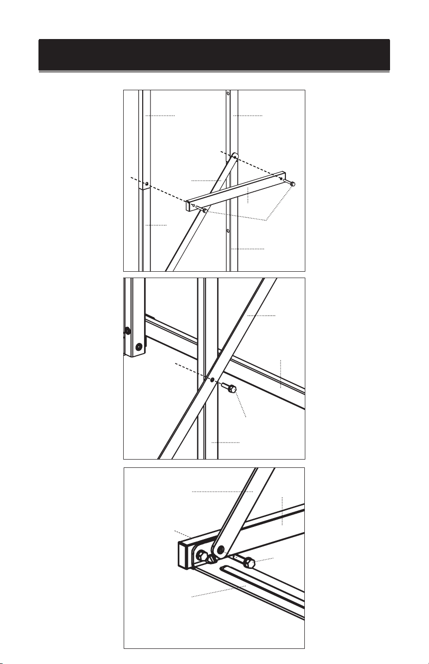
See next page for detail of each step.

Page 13
SET UP & USE
1R
1F
6
20S
Detail showing installation
of 6 (SUPPORT RAIL) and
then 7 (CONNECTING
RAIL).
Detail showing
installation of 6
(SUPPORT RAIL) with
the hole on the inside of
1F (Front Base).
35M
7
6
5R4R
2R
3R
25S
6
1B
2R

Page 14
SET UP & USE
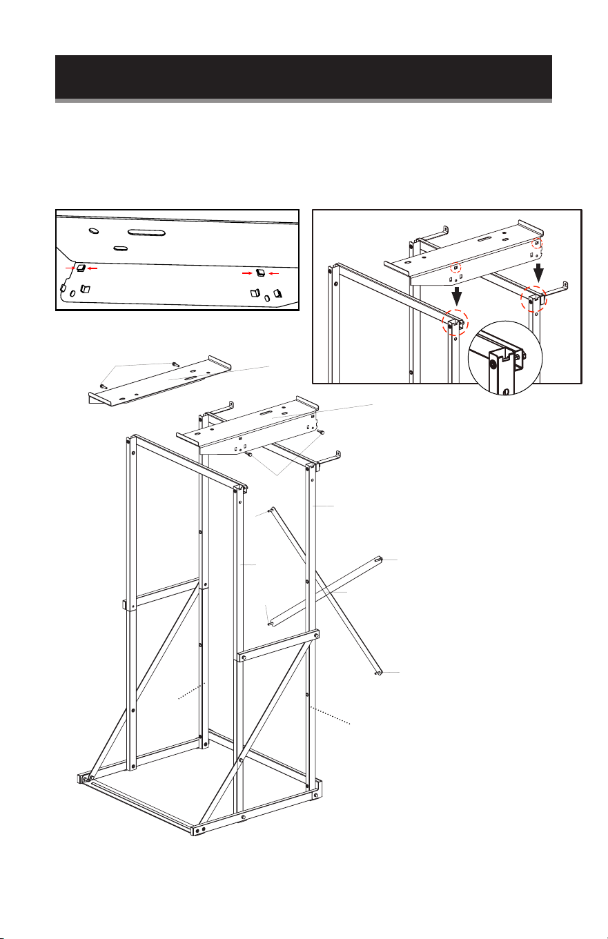
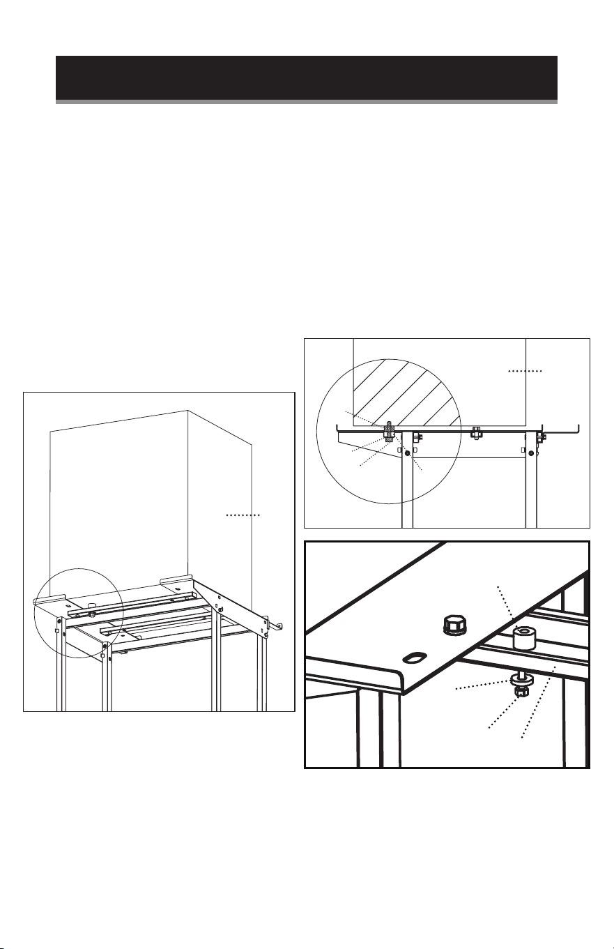
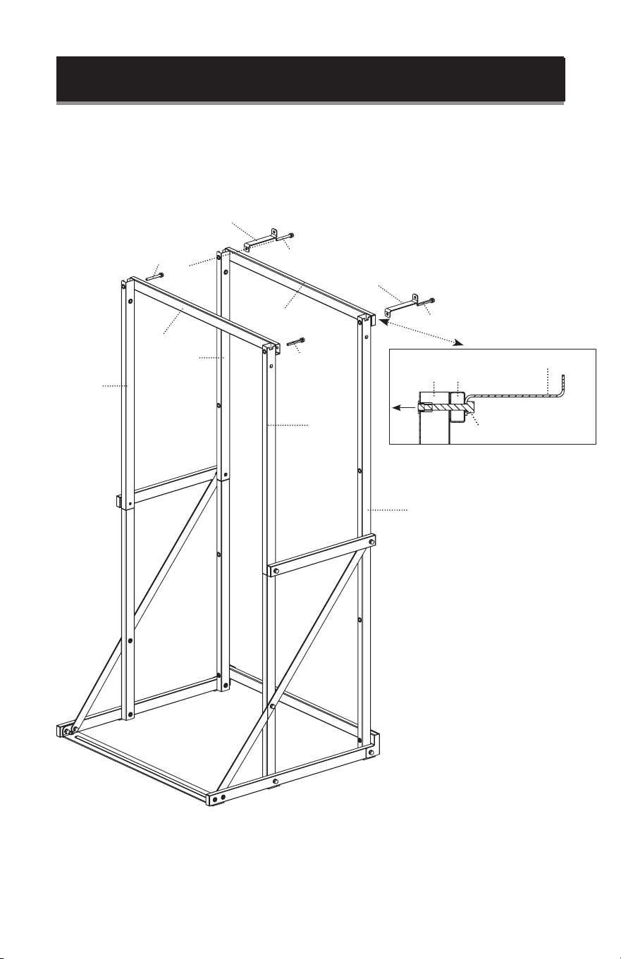
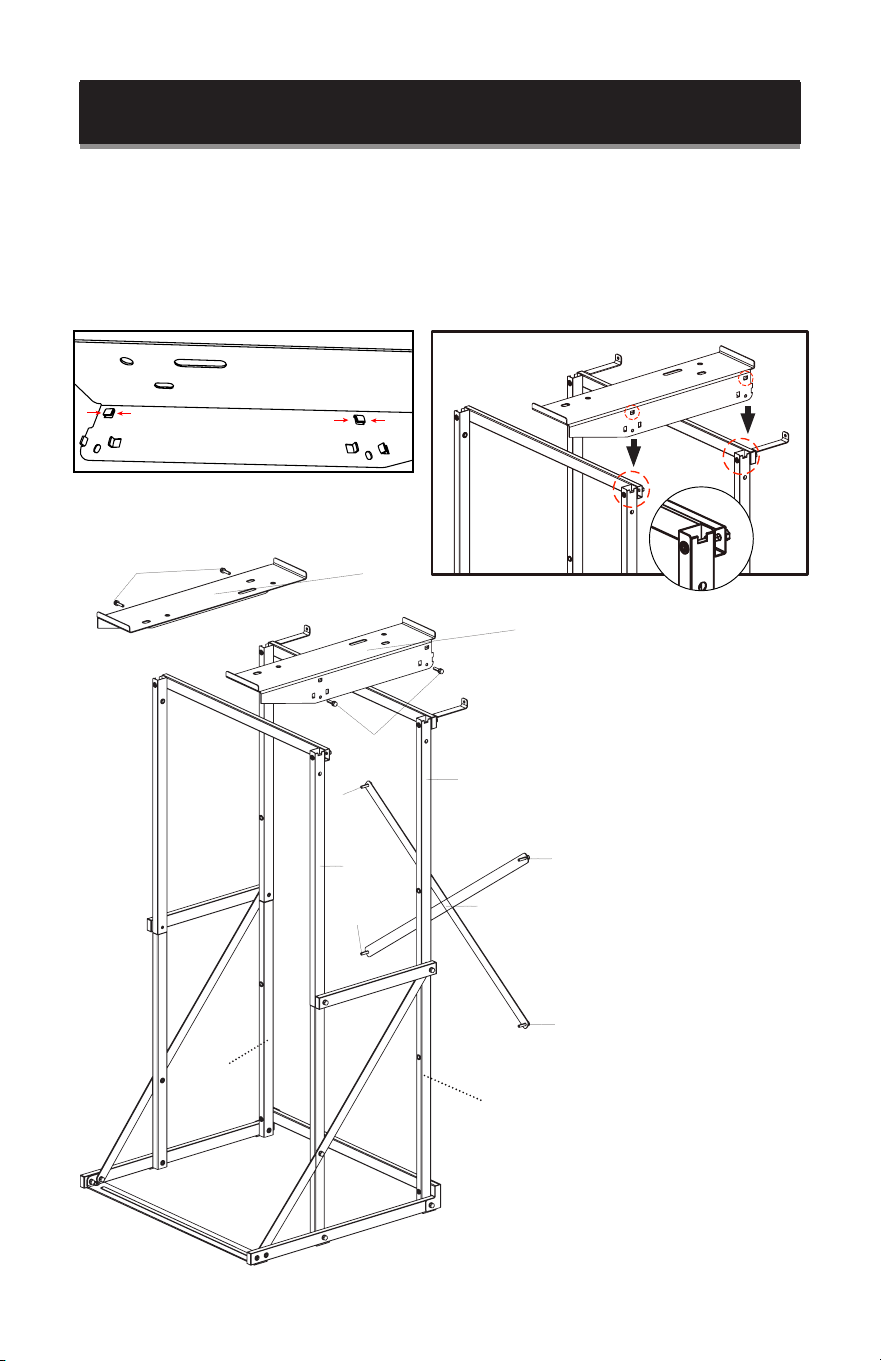
Line up the hole of one side of 1T (TOP REINFORCING BAR) with the top back hole
of 5R (UPPER RIGHT BACK VERTICAL POLE). Insert a 45L (45mm LONG SCREW)
through an ANTI-TIP BRACKET first, all the way through 1T (TOP REINFORCING
BAR) and secure into 5R (UPPER RIGHT BACK VERTICAL POLE).
NOTE: Follow the same steps to assemble the left side.
Line up the hole of one side of 2T (TOP REINFORCING BAR) with the top back hole
of 4R (UPPER RIGHT FRONT VERTICAL POLE). Insert a 45L (45mm LONG SCREW)
through 2T (TOP REINFORCING BAR) and secure into 4R (UPPER RIGHT FRONT
VERTICAL POLE).
NOTE: Follow the same steps to assemble the left side.
ANTI-TIP BRACKET
ANTI-TIP BRACKET
45L
45L
45L
2T
1T
45L
5R
4R
5L
4L
ANTI-TIP BRACKET
1T5R
45L
Page 15
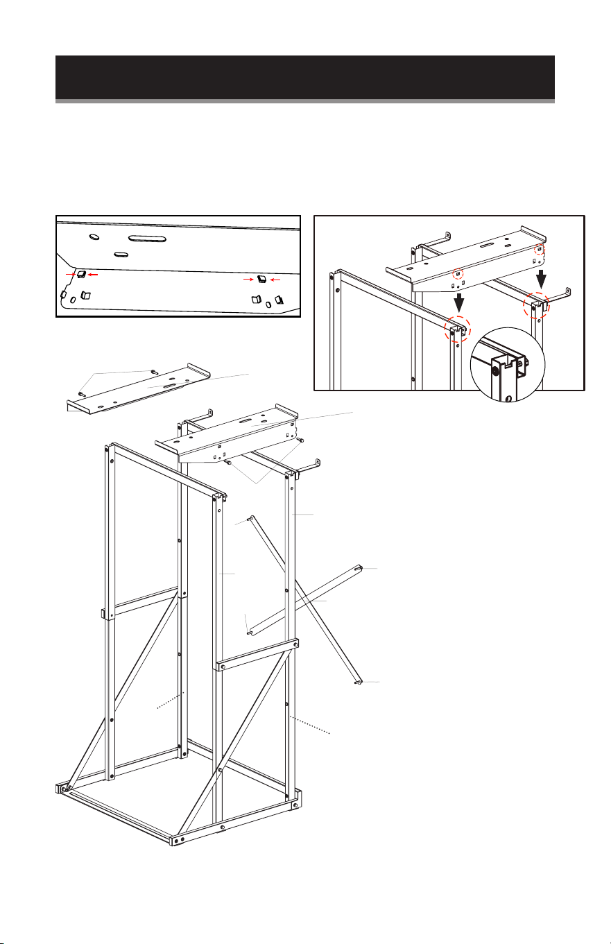
SET UP & USE
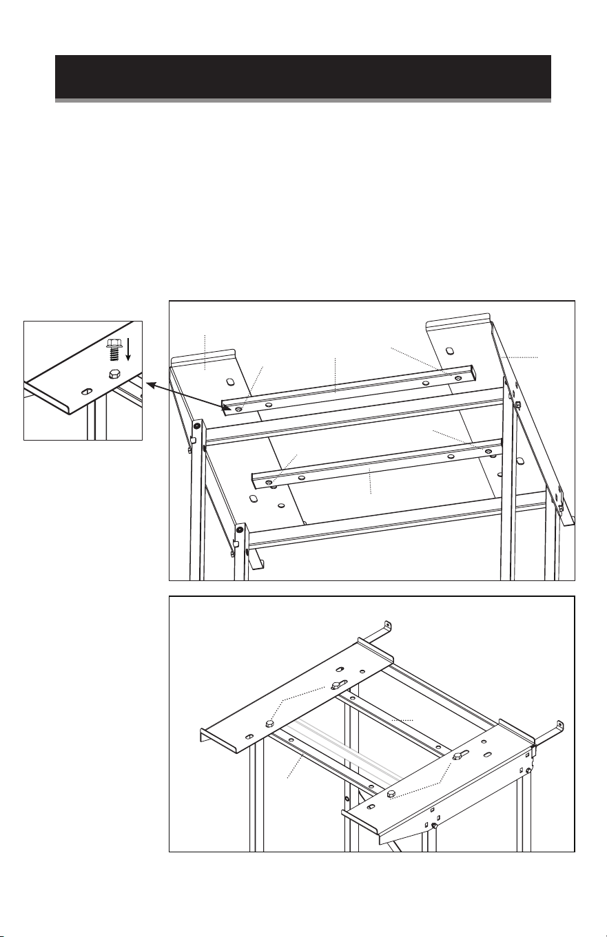
Align 8R (RIGHT DRYER SUPPORT) and insert into 4R (UPPER RIGHT FRONT VERTICAL POLE)
and 5R (UPPER RIGHT BACK VERTICAL POLE). Insert 25S screws from the exterior side of 8R
(RIGHT DRYER SUPPORT).
Align the holes of 2B (DIAGONAL SUPPORT RAIL) with holes in the back of 5R (UPPER RIGHT
BACK VERTICAL POLE), 3R (LOWER RIGHT BACK VERTICAL POLE), 5L (UPPER LEFT BACK
VERTICAL POLE), and 3L (LOWER LEFT BACK VERTICAL POLE). Then secure with 35M screws.
NOTE: Follow the same steps to assemble 8L (LEFT DRYER SUPPORT) to the left side.
When installing 8R (RIGHT DRYER SUPPORT) and 8L (LEFT DRYER SUPPORT) it is important to
make sure the tabs are inserted into the notches on the vertical poles as shown.
25S
25S
8L
8R
5R
4R
35M
35M
35M
35M
2B
3R
3L
Insert
Insert
Page 16
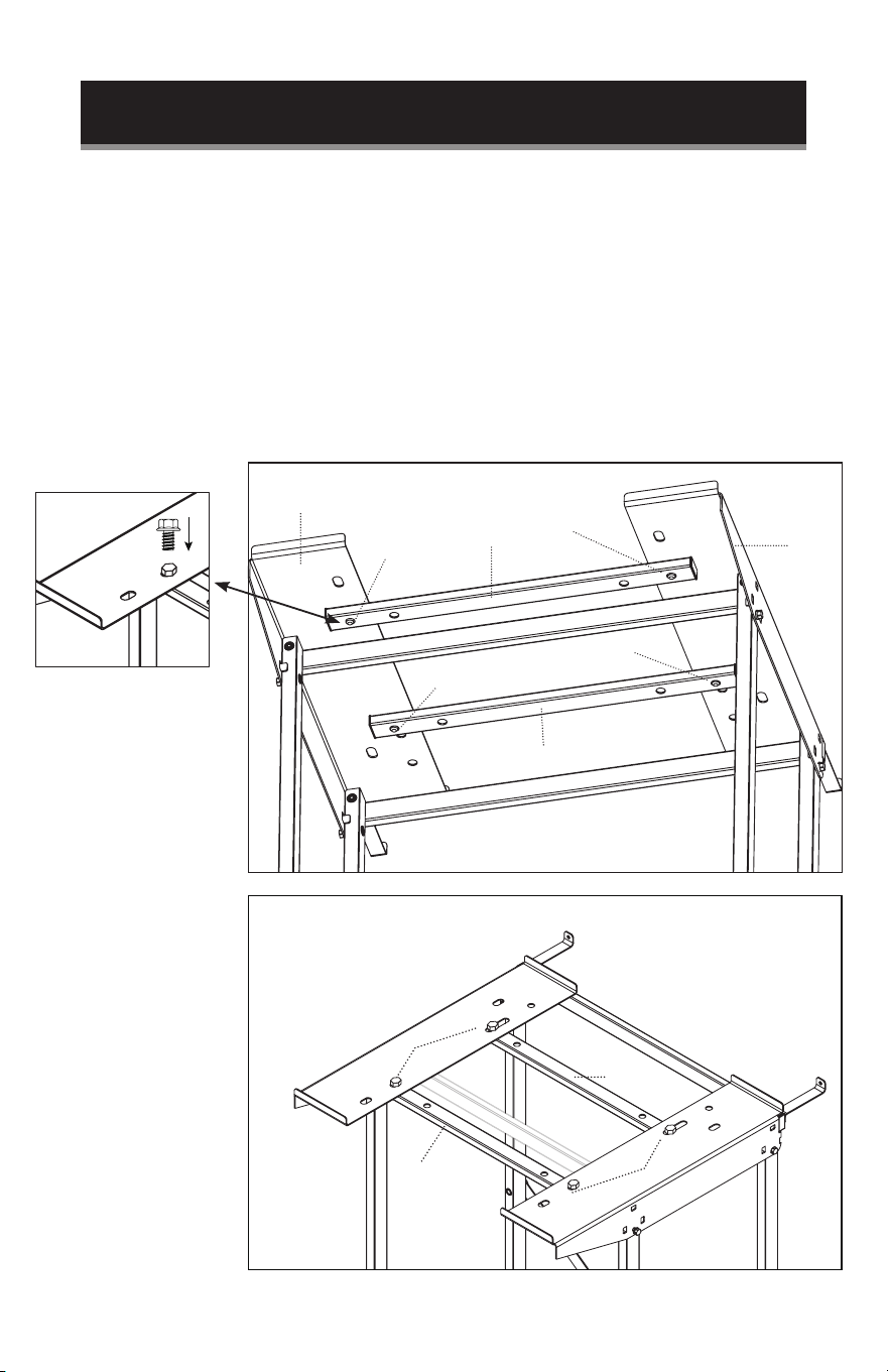
SET UP & USE
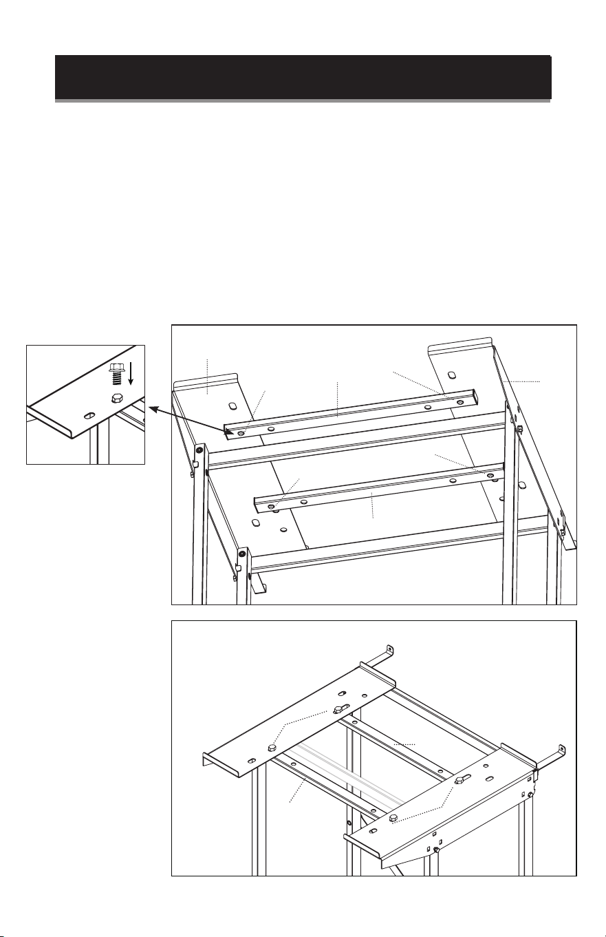
3T DRYER SUPPORT BARS only need to be installed if using with 1.5 cu. ft. dryer
model BCED15.
Position 3T (DRYER SUPPORT BAR) so the holes at the end are positioned
underneath the screw slots in the back of 8R (RIGHT DRYER SUPPORT) and 8L
(LEFT DRYER SUPPORT). Insert 20SD (20mm SHORT, LARGE DIAMETER SCREW)
through 8R (RIGHT DRYER SUPPORT) and then through 3T (DRYER SUPPORT
BAR). Insert 20SD (20mm SHORT, LARGE DIAMETER SCREW) through 8L (LEFT
DRYER SUPPORT) and then through 3T (DRYER SUPPORT BAR).
NOTE: Follow the same steps to assemble the other 3T (DRYER SUPPORT BAR) in
the front screw holes. Make sure to position the support bars and insert screws
as shown in the diagrams.
8R
3T
3T
3T
3T
8L
20SD
20SD
20SD
20SD
20SD
20SD
20SD
Bottom view
Top view
Page 17
SET UP & USE
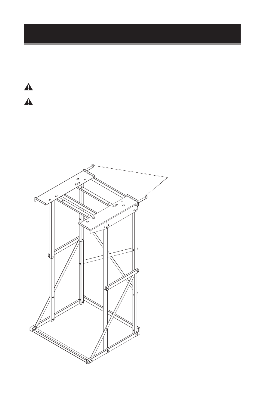
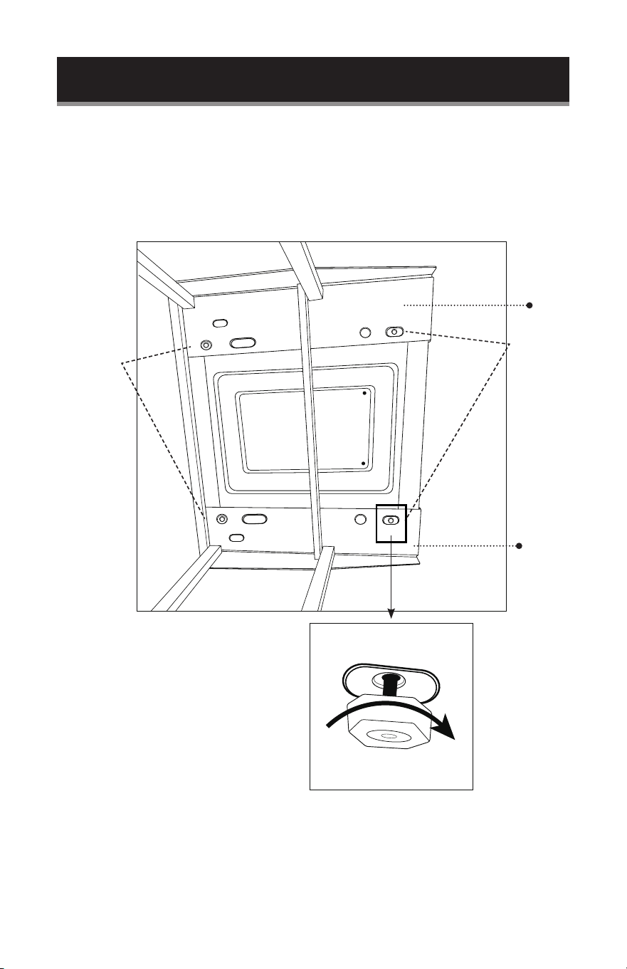
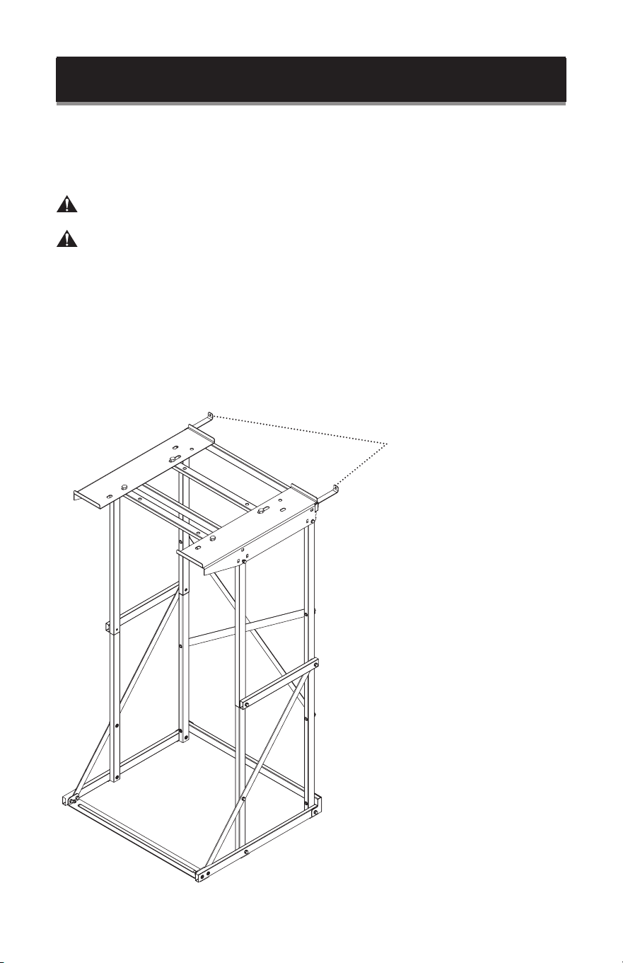
Tighten all the SCREWS and move the stand to where you intend to attach it to the
wall.
Mark the position on the wall where the holes of the ANTI-TIP BRACKET will connect
to the wall.
WARNING: To reduce the likelihood of injury or property damage, the anti-tip
feature must be properly installed and utilized.
WARNING:
Suitable lag type screws (included) will need to be used to properly anchor the
washer dryer stand to a rigid framing member. Rigid framing members could include
wood or metal studs and concrete blocks. If screwed into a wood framing member
using lag screws with a minimum diameter of 1/4” and 1-1/2” in length, mounting one
bracket on a wall stud will be sucient.
Before drilling or screwing, verify that there are no electric cables, plumbing pipes or
other potential hazards behind the wall where the lag screws are being installed.
ANTI-TIP BRACKETS
Page 18
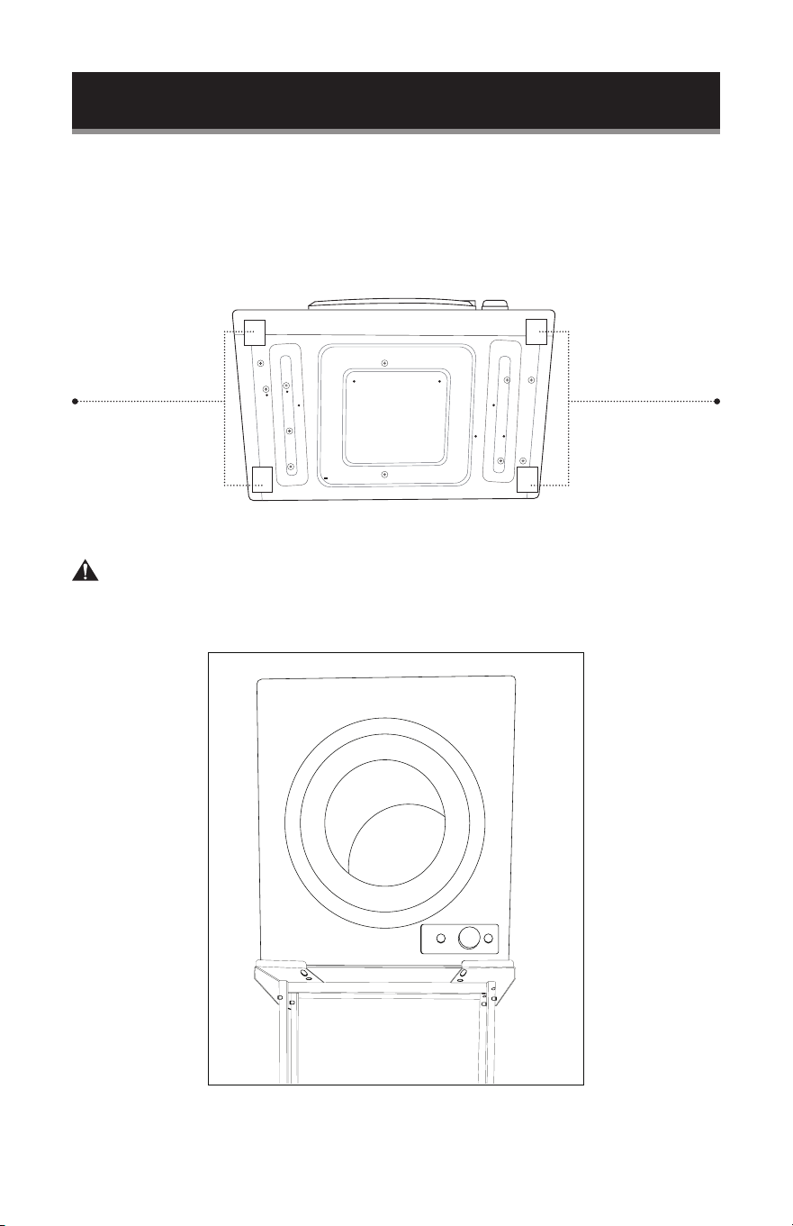
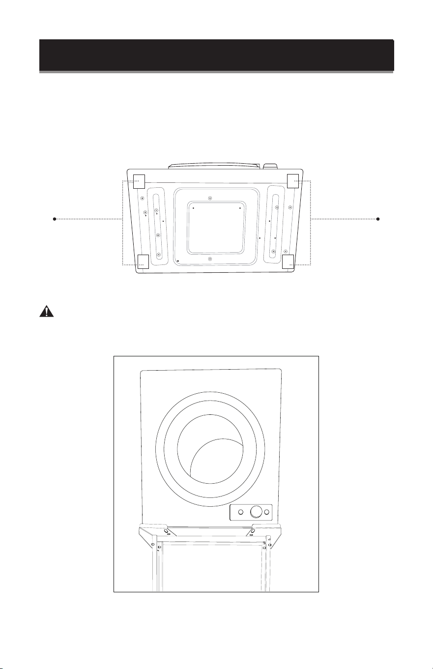
NON-SLIP PAD NON-SLIP PAD
BOTTOM VIEW OF DRYER
SET UP & USE
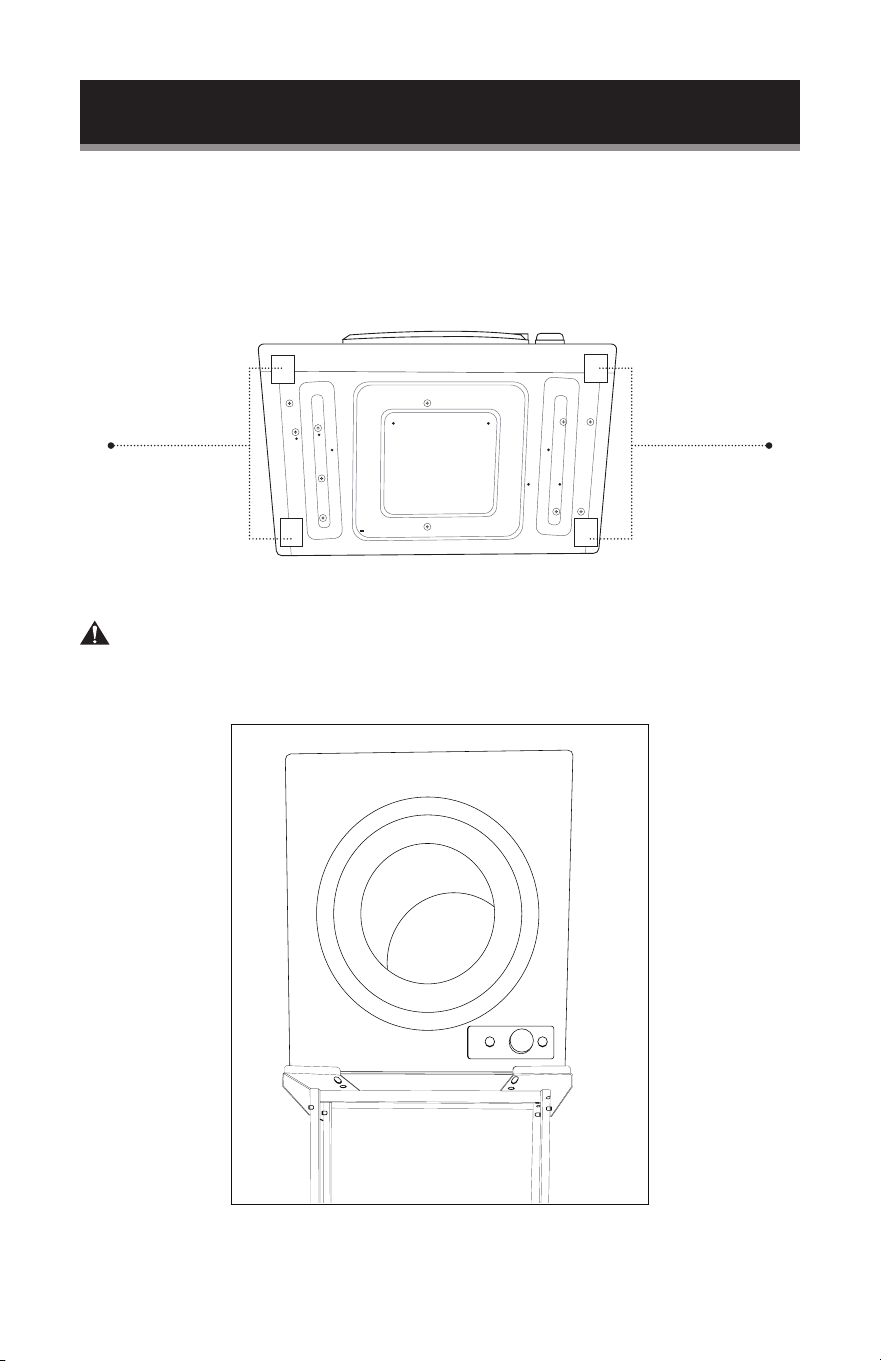
Installing the BCED26 and BCED37 or other compact dryer to the 8R (RIGHT
DRYER SUPPORT) and 8L (LEFT DRYER SUPPORT).
Place LARGE NON-SLIP PADS on the base of the dryer as illustrated. Make sure to
place NON-SLIP PADS where they will rest on the Dryer Rack to avoid slipping.
Remove the feet on the bottom of the dryer.
Place dryer on top of the rack.
WARNING: Dryer stand should only be used with dryers that have a flat
base or removable feet or legs. Do not remove dryer feet against
manufacturer recommendation.
Page 19
SET UP & USE
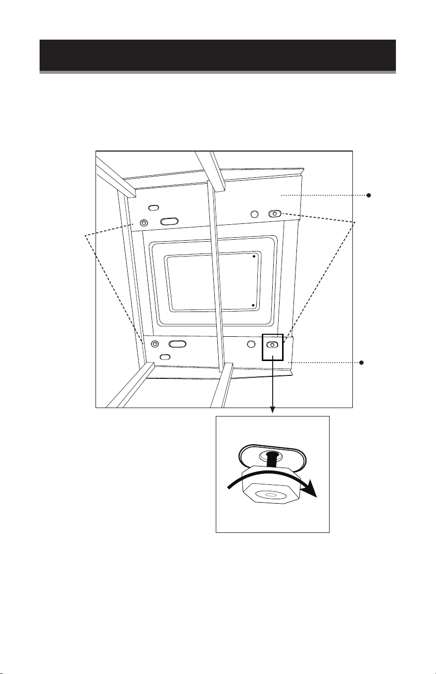
For BLACK+DECKER dryer models BCED26 and BCED37 position the dryer so the
holes of the dryer from the feet are aligned with the back holes of the top of the dryer
rack 8L (LEFT DRYER SUPPORT)and 8R (RIGHT DRYER SUPPORT). Re-install the
feet through the holes so the dryer is now anchored directly to the dryer stand.
For dryers that are not BLACK+DECKER brand, you can also secure one or more
of the feet through the back holes. If the dryer does not have removable feet or the
holes are not aligned with the holes on 8L (LEFT DRYER SUPPORT) and 8R (RIGHT
DRYER SUPPORT), the dryer can rest on top.
TIGHTEN
Insert Feet
Insert Feet
8L
8R

Page 20
SET UP & USE
Installing the BLACK+DECKER model BCED15 Dryer on the 3T (DRYER SUPPORT
BAR).
Remove the adhesive back from the (4) rubber spacers and place them so the hole in the
rubber spacer is aligned with the top of the 4 holes of 3T (DRYER SUPPORT BARS) where
the dryer will be anchored to.
Remove the feet on the bottom of the dryer.
Place dryer on top of the rack to align the holes from the previously removed feet with the
holes of the rubber spacer.
Insert 40LD (40mm LONG SCREW) into a washer and insert it upwards through the 3T
dryer support bar, the rubber spacer and through the hole of the dryer. Turn clockwise to
tighten.
NOTE: Follow the same steps to anchor the dryer to all 4 corners of the dryer.
Rubber Spacer
3T
40LD
Washer
Rubber
Spacer
Dryer
40LD
3T
Washer
Dryer
Page 20

Page 21
SET UP & USE
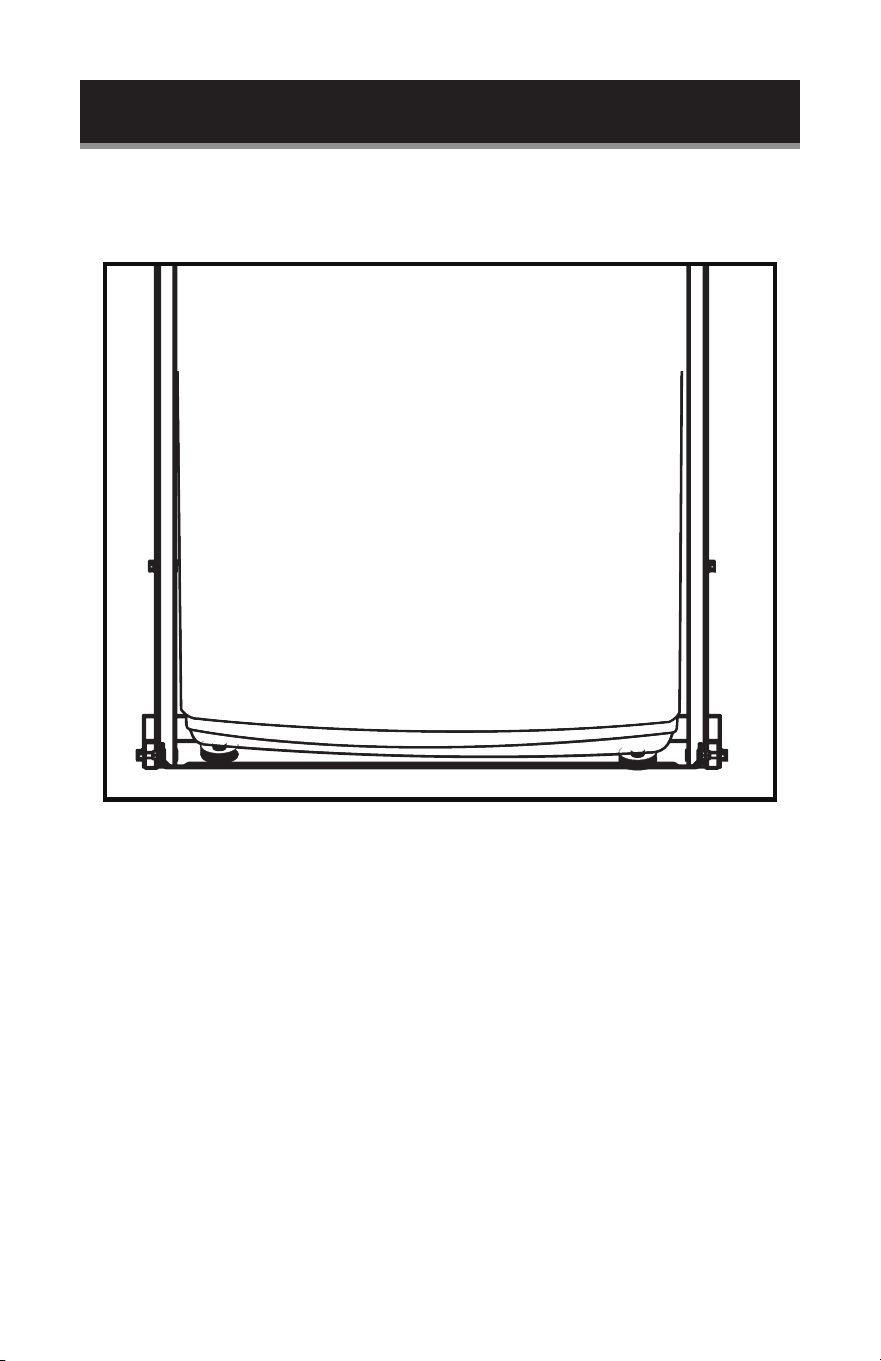
Place the washer in position, on the bottom of the rack. You will have to lift the
washer slightly to move over 1F (FRONT BASE).

Page 22
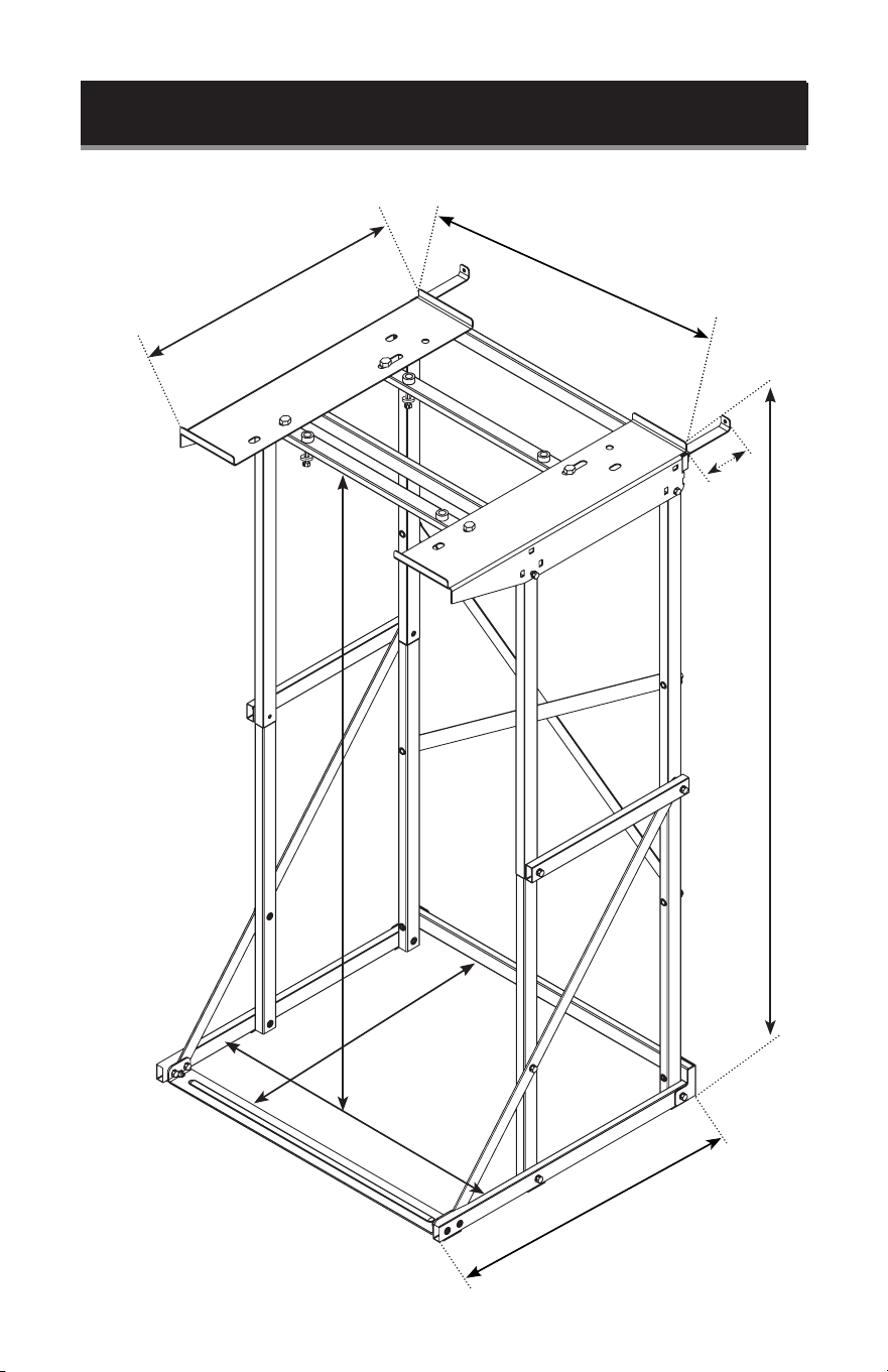
SET UP & USE
Fits Portable Dryers Maximum Weight of 60 lbs.
Total installed dimensions
Width 24.6"
Depth 27"
Height 50.86"
21.5”
24.57”
3.86”
50.86”
20.24”
48.9”
22.75”
23.15”
Page 22

Page 23
CLEANING & CARE
CLEANING AND MAINTENANCE
Use water or a mild soap and water solution to clean your washer dryer stand. Do not
use abrasive cleaners which may scratch the surface.
TROUBLESHOOTING & WARRANTY
IMPORTANT
DO NOT RETURN THIS PRODUCT TO THE STORE
If you have a problem with this product, please contact the
BLACK+DECKER Customer Satisfaction Center at
844-299-0879 or service@appliance.com.
DATED PROOF OF PURCHASE, MODEL # AND SERIAL #
REQUIRED FOR WARRANTY SERVICE

Page 24
TROUBLESHOOTING & WARRANTY
LIMITED WARRANTY
Any repair, replacement, or warranty service,
and all questions about this product should be
directed to W Appliance Co. at 844-299-0879
from the USA or Puerto Rico.
W Appliance warrants to the original purchaser that
the product will be free from defects in material,
parts and workmanship for the period designated for
this product. The warranty commences the day the
product is purchased and covers up to a period of
1 year (12 months) for labor/1 year (12 months) for
parts (manufacturing defects only). W Appliance
agrees that it will, at its option, replace the defective
product with either a new or remanufactured unit
equivalent to your original purchase during the
warranty period.
Exclusions: This warranty does not apply to the
below:
1. If the appearance or exterior of
the product has been damaged or
defaced, altered or modified in design or
construction.
2. If the product original serial number
has been altered or removed or cannot
be readily determined.
3. If there is damaged due to power line
surge, user damage to the AC power
cord or connection to improper voltage
source.
4. If damage is due to general misuse,
accidents or acts of God.
5. If repair attempts are done by
unauthorized service agents, use of
parts other than genuine parts or parts
obtained from persons other than
authorized service companies.
6. On units that have been transferred
from the original owner.
7. On products that have been purchased
as refurbished, like new, second-hand, in
a “As-Is” or “Final Sale” terms.
8. To products used in a commercial or
rental setting.
9. To products used in settings other than
ordinary household use or used other
than in accordance with the provided
instructions.
10. To damages for service calls for
improper installations.
11. Transportation and shipping costs
associated with the replacement of the
unit.
12. Service calls to instruct you how to use
your product.
13. Service calls to repair or replace the
house fuse, reset the circuit breaker or
correct the wiring in the house.
REPAIR OR REPLACEMENT AS PROVIDED UNDER
THIS WARRANTY IS THE EXCLUSIVE REMEDY OF
THE CUSTOMER; W APPLIANCE. SHALL NOT BE
LIABLE FOR ANY INCIDENTAL OR CONSEQUENTIAL
DAMAGES FOR BREACH OF ANY EXPRESS OR
IMPLIED WARRANTY ON THIS PRODUCT, EXCEPT
TO THE EXTENT PROHIBITED BY APPLICABLE LAW.
ANY IMPLIED WARRANTY OF MERCHANTABILITY
OF FITNESS FOR A PARTICULAR PURPOSE ON THIS
PRODUCT IS LIMITED TO THE DURATION OF THE
WARRANTY.
Some states do not allow the exclusion or limitations
of incidental or consequential damages, or limitations
on how long the warranty lasts. In these cases the
above exclusions or limitations may not apply to you.
This warranty gives you specific legal rights and you
may also have other rights which vary from state to
state.
Obtaining Service: To obtain service, product
literature, supplies or accessories please call
844-299-0879 to create a ticket for exchange/repair.
Please make sure to provide the date of purchase,
model number and a brief description of the problem.
Our customer service representative will contact you
or send detailed return instructions.
W Appliance does not warrant that the appliance will work
properly in all environmental conditions, and makes no warranty
and representation, either implied or expressed, with respect
to the quality, performance, merchantability, or fitness for a
particular purpose other than the purpose identified within this
user’s manual. W Appliance has made every eort to ensure
that this user’s manual is accurate and disclaims liability for any
inaccuracies or omissions that may have occurred. Information in
this user’s manual is subject to change without notice and does
not represent a commitment on the part of W Appliance.
W Appliance reserves the right to make improvements to this
user’s manual and/or to the products described in this user’s
manual at any time without notice. If you find information in this
manual that is incorrect, misleading, or incomplete, please contact
us at 844-299-0879.
W Appliance Co.
1356 Broadway
New York, NY 10018

Page 25
Page 25Page 25
BLACK & DECKER, BLACK+DECKER, the BLACK & DECKER and
BLACK+DECKER logos and product names are trademarks of The Black &
Decker Corporation, used under license. All rights reserved.
Product in this box may differ slightly from that pictured. Does not affect
function. Not all accessories shown in photography are included in this
package.
Imported by W Appliance, Inc., 1356 Broadway, New York, NY 10018
February 2024 Printed in China

Page 26
MANUEL D’INSTRUCTIONS
SUPPORT LAVEUSE-SÉCHEUSE
Merci d’avoir choisi BLACK+DECKER!
VEUILLEZ LIRE AVANT DE RETOURNER CE PRODUIT POUR
UNE RAISON QUELCONQUE.
Si vous avez une question ou rencontrez un problème avec votre achat
BLACK+DECKER, allez sur www.blackanddecker.com/instantanswers
Si vous ne trouvez pas la réponse ou n’avez pas accès à l’internet, appelez le
844-299-0879 de 10 h 30 à 18 h 30 HNE du lundi au vendredi pour parler avec
un agent. Veuillez avoir le numéro de catalogue disponible quand vous appelez.
GARDEZ CE MANUEL POUR RÉFÉRENCE FUTURE.
NUMÉRO DE CATALOGUE
BWDS

Page 27
INFORMATION DE SÉCURITÉ
Consignes de sécurité importantes ................................................................................................................................28
CONFIGURATION ET UTILISATION
Liste des pieces .................................................................................................................................................................29-30
Instructions de montage ................................................................................................................................31-46
dimensions du produit ..........................................................................................................................................47
NETTOYAGE ET ENTRETIEN ............................................................................................................... 48
DÉPANNAGE ET GARANTIE
Important ................................................................................................................................................................. 48
Garantie limitée ........................................................................................................................................................................49
TABLE DES MATIÈRES
ENREGISTREMENT DU PRODUIT
Agrafez votre reçu à votre manuel.
Vous en aurez besoin pour obtenir le service
de garantie.
Merci d’avoir acheté notre produit
BLACK+DECKER. Ce manuel facile
à utiliser vous guidera pour tirer le
meilleur parti de votre produit.
N’oubliez pas d’enregistrer les
numéros de modèle et de série. Ils
sont sur une étiquette à l’arrière du
produit.
_____________________________
Numéro de modèle
_____________________________
Numéro de série
_____________________________
Date d’achat
Page 28
LIRE TOUTES LES INSTRUCTIONS AVANT UTILISATION.
AVERTISSEMENT:
• Poids Maximum pour le Support de Sécheuse 60 lbs. Ne dépassez pas la limite de
poids maximale.
• Ce support de laveuse-sécheuse doit être ancré à un mur à l’aide de supports
anti-basculement pour éviter le basculement.
RISQUE DE BLESSURE CORPORELLE OU DE DÉCÈS, LE SUPPORT DOIT ÊTRE
FIXÉ À UN ÉLÉMENT DE CHARPENTE RIGIDE DU MUR ADJACENT AVANT
UTILISATION.
• Certaines pièces d’assemblage peuvent provoquer un étouffement. Garder loin des
enfants.
• Ne vous appuyez pas ou ne laissez pas les enfants jouer ou grimper sur le support
de laveuse-sécheuse. Ne laissez pas les enfants se suspendre de la porte de la
sécheuse lorsqu’ils sont assis sur le dessus du support de laveuse-sécheuse, car cela
pourrait le faire basculer.
GARDEZ CES INSTRUCTIONS
USAGE DOMESTIQUE UNIQUEMENT
AVERTISSEMENT
Lors de l’utilisation du support de laveuse-sécheuse, des précautions
de sécurité de base doivent être suivies, y compris les suivantes:
DANGER
DANGER - Dangers immédiats qui
ENTRAÎNERONT des blessures
graves ou la mort.
AVERTISSEMENT
AVERTISSEMENT - Dangers ou
pratiques dangereuses POUVANT
entraîner des blessures graves ou
la mort.
ATTENTION
ATTENTION - Risques ou pratiques
dangereuses POUVANT entraîner
des blessures mineures.
CONSIGNES DE SÉCURITÉ IMPORTANTES
INFORMATION SUR LA SÉCURITÉ

Page 29
CONFIGURATION ET UTILISATION
Outils Requis: Tournevis et perceuse (non inclus)
REMARQUE:
20S = 4 vis courtes de 20mm.
Utilisé pour installer le support de base avant sur les rails de base latéraux. Doit être
inséré de manière à ce que la tête de vis se trouve sur le côté intérieur de la base
avant.
20SD = 4 vis courtes de 20mm de grand diamètre. Utilisé pour les barres de support
de sécheuse 3T. Doit être inséré par le haut des supports de sécheuse.
25S = 6 vis courtes de 25mm
Utilisé pour installer le support de sécheuse sur les poteaux verticaux supérieurs et
les rails de support latéraux sur les poteaux verticaux inférieurs. Doit être inséré de
manière à ce que la tête de vis soit à l’extérieur de l’unité.
35M = 12 vis moyennes de 35mm. Connecte les rails de support diagonaux, les
rails latéraux et les rails de connexion aux poteaux verticaux et installe les poteaux
verticaux à la base. Doit être inséré de manière à ce que la tête de vis soit à l’extérieur
de l’unité.
40LD = 4 vis longues de 40mm. Utilisé uniquement lors de l’installation de la
Sécheuse BCED15 (vendu séparément). Utilisé pour connecter la sécheuse BCED15
aux barres de support de sécheuse. Doit être inséré par le bas de la barre de support
de sécheuse. Ces vis ne seront pas nécessaires pour la connexion de sécheuse de plus
grande taille.
45L = 6 vis longues de 45mm. Utilisé pour connecter des poteaux verticaux aux
barres de renfort. Doit d’abord être inséré à travers le rail vertical, puis serré dans les
Barres de Renfort.
REMARQUE: Il est important d’utiliser la bonne vis et de l’insérer à l’emplacement
indiqué dans les instructions. Pour installer les vis, utilisez la clé incluse ou le tournevis
(non inclus). Insérez et tournez vers la droite jusqu’à ce que toute la partie filetée de
la vis soit complètement insérée.

Page 30
CONFIGURATION ET UTILISATION
ID DESCRIPTION QUANTITÉ
1F BASE AVANT 1
1B BASE ARRIÈRE 1
2B RAIL DE SUPPORT DIAGONAL 1
1R BASE DROIT 1
2R POTEAU VERTICAL AVANT INFÉRIEUR DROIT 1
3R POTEAU VERTICAL ARRIÈRE INFÉRIEUR DROIT 1
4R POTEAU VERTICAL AVANT SUPÉRIEUR DROIT 1
5R POTEAU VERTICAL ARRIÈRE SUPÉRIEUR DROIT 1
8R SUPPORT DE SÉCHEUSE DROIT 1
1L BASE GAUCHE 1
2L POTEAU VERTICAL AVANT INFÉRIEUR GAUCHE 1
3L POTEAU VERTICAL ARRIÈRE INFÉRIEUR GAUCHE 1
4L POTEAU VERTICAL AVANT SUPÉRIEUR GAUCHE 1
5L POTEAU VERTICAL ARRIÈRE SUPÉRIEUR GAUCHE 1
8L SUPPORT DE SÉCHEUSE GAUCHE 1
6 RAIL DE SUPPORT LATÉRAL 2
7 RAIL DE CONNEXION 2
1T BARRE DE RENFORT (BOUCHONS À L’EXTRÉMITÉ) 1
2T BARRE DE RENFORT 1
3T BARRE DE SUPPORT DE SÉCHEUSE (À UTILISER AVEC LE MODÈLE BCED15) 2
SUPPORT ANTI-BASCULEMENT 2
SUPPORT D’ANGLE 2
COUSSINETS ANTIDÉRAPANTS - PETITS (POUR LE BAS DU SUPPORT) 6
COUSSINETS ANTIDÉRAPANTS - GRAND (POUR LE BAS DE SÉCHEUSE) 4
RONDELLE EN CAOUTCHOUC (UTILISÉE POUR FIXER UNE SÉCHEUSE BCED15 DE
PETITE CAPACITÉ)
4
RONDELLE (UTILISÉE POUR FIXER LA SÉCHEUSE BCED15 DE PETITE CAPACITÉ) 4
20S VIS COURTE 20MM 4
20SD
VIS COURTE 20MM DE GRAND DIAMÈTRE (POUR LA BARRE DE SUPPORT DE
SÉCHEUSE T3)
4
25S VIS COURTE 25MM 6
35M VIS MOYENNE 35MM 12
40LD
VIS LONGUE 40MM (SERVANT A FIXER UNE SÉCHEUSE BCED15 DE PETITE
CAPACITÉ)
4
45L VIS 45MM DE LONG 6
VIS DE TYPE TIRE-FOND (POUR FIXER LE SUPPORT DE SÉCHEUSE AU MUR ) 2
CLÉ 1
Page 31
CONFIGURATION ET UTILISATION
PIÈCES ET CARACTÉRISTIQUES
Support
anti-basculement
Support anti-basculement
8R
8L
3T
40LD
3T
1T
2T
2B
1B
6
6
7
7
25S
25S
4R
4L
2L
3L
35M
35M
35M
35M
35M
35M
35M
35M
35M
35M
35M
5L
5R
25S
25S
25S
25S
3R
Support d’angle
1R
45L
45L
1L
1F
2R
20S
20S
Entretoises en
caoutchouc
Rondelles
Page 32
CONFIGURATION ET UTILISATION
7
2B
6
Support anti-basculement
Vis tire-fond
1T 2T
3T
20S
20SD
40LD
25S 35M 45L
Tapis antidérapant 1.6”x.6”
Grands patins antidérapants
1.97”x1.97”
1F
8L 8R
Support d’angle
1B
Rondelles
Entretoises en caoutchouc
CLÉ
1R 2R 3R 4R
5R
1L 2L 3L 4L 5L

Page 33
CONFIGURATION ET UTILISATION
Alignez les 2 trous de 1R (SUPPORT DE BASE DROIT) avec le côté droit de 1F (BASE
AVANT). Insérez 20S (VIS COURTE 20mm) à travers le trou de vis sur le côté extérieur
de 1F (BASE AVANT) jusqu’à ce qu’il soit fermement fixé dans 1R (BASE DROIT).
Alignez les 2 trous de 1L (BASE GAUCHE) avec le côté gauche de 1F (BASE AVANT).
Insérez 20S (VIS COURTE 20mm) à travers le trou de vis sur le côté extérieur de 1F
(BASE AVANT) jusqu’à ce qu’il soit fermement fixé dans 1L (BASE GAUCHE).
Retirez le dos adhési des (6) COUSSINETS ANTIDÉRAPANTS PETITS (1,6pox0,6po).
Placez le côté collant sur la base de l’appareil comme indiqué sur le schéma.
1L
1R
1F
20S
20S
PETITS PADS ADHÉSIFS
ANTIDÉRAPANTS x6
#1
#2
#3
#4
#5
#6

Page 34
CONFIGURATION ET UTILISATION
En utilisant le schéma ci-dessous comme référence pour positionner les poteaux,
INSÉREZ 2R (POTEAU VERTICAL AVANT INFÉRIEUR DROIT) dans IR (BASE DROIT).
La base des poteaux doit être positionnée entre les fentes 1R (BASE DROIT) et
alignée avec les trous. Utilisez 35M (VIS MOYENNES 35mm) pour fixer. Il doit être
inséré de l’extérieur de 1R (BASE DROIT) et inséré complètement à travers le trou du
poteau pour le fixer.
REMARQUE: Suivez les mêmes étapes pour insérer 2L (POTEAU VERTICAL AVANT
INFÉRIEUR GAUCHE) dans 1L (BASE GAUCHE) sur le côté gauche.
2L
1L
1L
1L
1F
2L
1R
2R

Page 35
CONFIGURATION ET UTILISATION
3L
3R
45L
1B
45L
Support d’angle
35M
35M
35M
35M
2R
1L
1F
2L
1R
Insérez 3R (POTEAU VERTICAL ARRIÈRE INFÉRIEUR DROIT) dans la fente arrière de
1R (BASE DROIT).
Alignez avec le trou de 1B (BASE ARRIÈRE) et le SUPPORT D’ANGLE. Insérez 45L
(VIS LONGUE 45mm) à travers le trou du (SUPPORT D’ANGLE), 1B (BASE ARRIÈRE),
et puis 3R (POTEAU VERTICAL ARRIÈRE INFÉRIEUR DROIT).
Ajoutez 35M (VIS MOYENNE 35mm) à travers le trou restant du (SUPPORT
D’ANGLE) et insérez-le dans 3R (POTEAU VERTICAL ARRIÈRE INFÉRIEUR DROIT).
REMARQUE: Suivez les mêmes étapes pour assembler le côté gauche.
1B
3R
Support
d’angle
1R
35M
45L
Page 36
CONFIGURATION ET UTILISATION
Insérez 4R (POTEAU VERTICAL AVANT SUPÉRIEUR DROIT) dans 2R (POTEAU
VERTICAL AVANT INFÉRIEUR DROIT).
Insérez 5R (POTEAU VERTICAL ARRIÈRE SUPÉRIEUR DROIT) dans 3R (POTEAU
VERTICAL ARRIÈRE INFÉRIEUR DROIT).
Insérez 4L (POTEAU VERTICAL AVANT SUPÉRIEUR GAUCHE) dans 2L (POTEAU
VERTICAL AVANT INFÉRIEUR GAUCHE).
Insérez 5L (POTEAU VERTICAL ARRIÈRE SUPÉRIEUR GAUCHE) dans 3L (POTEAU
VERTICAL ARRIÈRE INFÉRIEUR GAUCHE).
4L
5L
4R 5R
3R
2R
3L
2L
Page 37
Alignez le trou d’un côté d’un 6 (RAIL DE SUPPORT), puis le 7 (RAIL DE
CONNEXION) avec le trou du côté extérieur du 5R (POTEAU VERTICAL ARRIÈRE
SUPÉRIEUR DROIT). Fixez avec 35M (VIS MOYENNE 35mm).
Alignez le trou restant du 7 (RAIL DE CONNEXION) avec le trou sur le côté extérieur
du 4R (POTEAU VERTICAL AVANT SUPÉRIEUR DROIT). Fixez avec 35M (VIS
MOYENNE 35mm).
Alignez le trou central du 6 (RAlL DE SUPPORT) avec le trou à l’extérieur de 2R
(POTEAU VERTICAL AVANT INFÉRIEUR DROIT), fixez-le avec 25S (PETITE VIS
25mm).
Alignez le dernier trou du 6 (RAIL DE SUPPORT) avec le trou à l’intérieur du 1F (Base
Avant). Fixez avec 20M (PETITE VIS 20mm).
REMARQUE: Suivez les mêmes étapes pour assembler le côté gauche.
35M
35M
7
7
25S
2R
4R 5R
3R
25S
20S
20S
6
6
Voir la page suivante pour le détail
de chaque étape.
CONFIGURATION ET UTILISATION
Page 38
1R
1F
6
20S
Détail montrant
l’installation du 6 (RAIL
DE SUPPORT) puis du 7
(RAIL DE CONNEXION).
Détail montrant
l’installation du 6 (RAIL
DE SUPPORT) avec le
trou à l’intérieur du 1F
(Base avant).
35M
7
6
5R4R
2R
3R
25S
6
1B
2R
CONFIGURATION ET UTILISATION

Page 39
Alignez le trou d’un côté de 1T (BARRE DE RENFORT SUPÉRIEURE) avec le trou
arrière supérieur de 5R (POTEAU VERTICAL ARRIÈRE SUPÉRIEUR DROIT). Insérez
d’abord un 45L (VIS LONGUE 45mm) à travers un SUPPORT ANTI-BASCULEMENT,
tout au long de 1T (BARRE DE RENFORT SUPÉRIEURE) et fixez-le dans 5R (POTEAU
VERTICAL ARRIÈRE SUPÉRIEUR DROIT).
REMARQUE: Suivez les mêmes étapes pour assembler le côté gauche.
Alignez le trou d’un côté de 2T (BARRE DE RENFORT SUPÉRIEURE) avec le trou
arrière supérieur de 4R (POTEAU VERTICAL AVANT SUPÉRIEUR DROIT). Insérez un
45L (VIS LONGUE 45mm) à travers 2T (BARRE DE RENFORT SUPÉRIEURE) et
fixez-la dans 4R (POTEAU VERTICAL AVANT SUPÉRIEUR DROIT).
REMARQUE: Suivez les mêmes étapes pour assembler le côté gauche.
Support anti-basculement
Support anti-basculement
45L
45L
45L
2T
1T
45L
5R
4R
5L
4L
Support anti-basculement
1T5R
45L
CONFIGURATION ET UTILISATION
Page 40
Alignez 8R (SUPPORT DE SÉCHEUSE DROIT) et insérez dans 4R (POTEAU VERTICAL AVANT
SUPÉRIEUR DROIT) et 5R (POTEAU VERTICAL ARRIÈRE SUPÉRIEUR DROIT). Insérez les vis 25S
du côté extérieur du 8R (SUPPORT DE SÉCHEUSE DROIT).
Alignez les trous de 2B (RAIL DE SUPPORT
DIAGONAL) avec les trous à l’arrière de 5R
(POTEAU VERTICAL ARRIÈRE SUPÉRIEUR
DROIT), 3R (POTEAU VERTICAL ARRIÈRE
INFÉRIEUR DROIT), 5L (POTEAU VERTICAL
ARRIÈRE SUPÉRIEUR GAUCHE) et 3L
(POTEAU VERTICAL ARRIÈRE INFÉRIEUR
GAUCHE). Fixez ensuite à l’aide de vis 35M.
REMARQUE: Suivez les mêmes étapes pour assembler 8L (SUPPORT DE SÉCHEUSE GAUCHE)
sur le côté gauche. Lors de l’installation du 8R (SUPPORT DROIT DE LA SÉCHEUSE) et du 8L
(SUPPORT GAUCHE DE LA SÉCHEUSE), il est important de s’assurer que les languettes sont
insérées dans les encoches sur les poteaux verticaux, comme illustré.
CONFIGURATION ET UTILISATION
25S
25S
8L
8R
5R
4R
35M
35M
35M
35M
2B
3R
3L
Insert
Insert
Page 41
Les BARRES DE SUPPORT POUR SÉCHEUSE 3T ne doivent être installées que si
elles sont utilisées avec 1,5 cu. Sécheuse de pieds modèle BCED15.
Positionnez 3T (BARRE DE SUPPORT DE SÉCHEUSE) de sorte que les trous à
l’extrémité soient positionnés sous les fentes de vis à l’arrière du 8R (SUPPORT DE
SÉCHEUSE DROIT) et du 8L (SUPPORT DE SÉCHEUSE GAUCHE). Insérez 20SD (VIS
COURTE GRAND DIAMÈTRE 20mm) à travers 8R (SUPPORT DE SÉCHEUSE DROIT),
puis à travers 3T (BARRE DE SUPPORT DE SÉCHEUSE). Insérez 20SD (VIS COURTE
GRAND DIAMÈTRE 20mm) à travers 8L (SUPPORT GAUCHE DE SÉCHEUSE), puis à
travers 3T (BARRE DE SUPPORT DE SÉCHEUSE).
REMARQUE: Suivez les mêmes étapes pour assembler les autres 3T (BARRE DE
SUPPORT DE SÉCHEUSE) dans les trous de vis avant. Assurez-vous de
positionner les barres de support et d’insérer des vis comme indiqué sur
les schémas.
8R
3T
3T
3T
3T
8L
20SD
20SD
20SD
20SD
20SD
20SD
20SD
Vue de dessous
Vue de dessus
CONFIGURATION ET UTILISATION

Page 42
Serrez toutes les VIS et déplacez le support à l’endroit où vous avez l’intention de le
fixer au mur.
Marquez la position sur le mur où les trous du SUPPORT ANTI-BASCULEMENT se
fixeront au mur.
AVERTISSEMENT: Pour réduire la probabilité de blessures ou de dommages
matériels, la fonction anti-basculement doit être correctement
installée et utilisée.
AVERTISSEMENT:
Des vis de type tire-fond appropriées (incluses) devront être utilisées pour ancrer
correctement le support de laveuse-sécheuse à un élément de charpente rigide.
Les éléments de charpente rigides peuvent inclure des poteaux en bois ou en métal
et des blocs de béton. S’il est vissé dans un élément de charpente en bois à l’aide
de tire-fonds d’un diamètre minimum de 1/4” et 1/2” de longueur, le montage d’un
support sur un montant mural sura.
Avant de percer ou de visser, vérifiez qu’il n’y a pas de câbles électriques, tuyaux de
plomberie ou autres dangers potentiels derrière le mur où les tire-fonds sont installés.
SUPPORT ANTI-BASCULEMENT
CONFIGURATION ET UTILISATION
Page 43
SUPPORT ANTI-BASCULEMENT
COUSSIN
ANTIDÉRAPANT
COUSSIN
ANTIDÉRAPANT
VUE INFÉRIEURE DU SÉCHOIR
Installation du BCED26 et du BCED37 ou d’une autre sécheuse compact sur le 8R
(SUPPORT DE SÉCHEUSE DROIT) et le 8L (SUPPORT DE SÉCHEUSE GAUCHE).
Placez les GRANDS COUSSINETS ANTIDÉRAPANTS sur la base de sécheuse comme
illustré. Assurez-vous de placer les COUSSINETS ANTIDÉRAPANTS à l’endroit où ils
reposeront sur le Support de Sécheuse pour éviter de glisser.
Enlevez les pieds au bas de la sécheuse.
Placez la sécheuse sur le dessus du support.
AVERTISSEMENT: Le support de sécheuse ne doit être utilisé qu’avec des
sécheuses à base plate ou à pieds ou pattes amovibles. Ne
retirez pas les pieds de la sécheuse contre la recommandation
du fabricant.
CONFIGURATION ET UTILISATION
Page 44
Pour les modèles de sécheuse BLACK+DECKER BCED26 et BCED37 positionnez
la sécheuse de sorte que les trous de la sécheuse depuis les pieds soient alignés
avec les trous arrière du haut du suppoer de sécheuse 8L (SUPPORT DE SÉCHEUSE
GAUCHE) et 8R (SUPPORT DE SÉCHEUSE DROIT). Réinstallez les pieds à travers
les trous afin que la sécheuse soit maintenant ancrée directement sur le support de
sécheuse.
Pour les sécheuses qui ne sont pas de marque BLACK+DECKER, vous pouvez
également fixer un ou plusieurs des pieds à travers les trous arrière. Si la sécheuse
n’a pas de pieds amovibles ou si les trous ne sont pas alignés avec les trous sur 8L
(SUPPORT DE SÉCHEUSE GAUCHE) et 8R (SUPPORT DE SÉCHEUSE DROIT), la
sécheuse peut reposer sur le dessus.
SERRER
Insérer
des pieds
Insérer des
pieds
8L
8R
CONFIGURATION ET UTILISATION
Page 45
Installation de la Sécheuse BLACK+DECKER modèle BCED15 sur la 3T (BARRE DE
SUPPORT).
Retirez le dos adhésif des (4) rondelles en caoutchouc et placez-les de sorte que le trou
dans la rondelle en caoutchouc soit aligné avec le haut des 4 trous de 3T (BARRES DE
SUPPORT DE SÉCHEUSE) où la sécheuse sera ancrée.
Enlevez les pieds au bas de la sécheuse.
Placez la sécheuse sur le dessus du support pour aligner les trous des pieds précédemment
retirés avec les trous de la rondelle en caoutchouc.
Insérez 40LD (VIS LONGUE 40mm) dans une rondelle et insérez-la vers le haut à travers
la barre de support de sécheuse 3T, la rondelle en caoutchouc et à travers le trou de la
sécheuse. Tournez dans le sens horaire pour serrer.
REMARQUE: Suivez les mêmes étapes pour ancrer la sécheuse aux 4 coins de la sécheuse.
Entretoise en caoutchouc
3T
40LD
Machine à
laver
Entretoise en
caoutchouc
Séchoir
40LD
3T
Machine
à laver
Séchoir
CONFIGURATION ET UTILISATION
Page 46
Placez la rondelle en position, sur le bas du support, Vous devrez soulever
légèrement la rondelle pour passer par-dessus IF (BASE AVANT).
CONFIGURATION ET UTILISATION

Page 47
Convient aux sécheuses portatives pesant jusqu’à 60 lb.
Dimensions totales installées
Largeur 24,6”
Profondeur 27”
Hauteur 50,86”
21.5”
24.57”
3.86”
50.86”
20.24”
48.9”
22.75”
23.15”
CONFIGURATION ET UTILISATION

Page 48
NETTOYAGE ET ENTRETIEN
NETTOYAGE ET ENTRETIEN
Utilisez de l’eau ou une solution d’eau et de savon doux pour nettoyer votre support
de laveuse-sécheuse. N’utilisez pas de nettoyants abrasifs qui pourraient rayer la
surface.
SERVICE CLIENT
IMPORTANT
NE PAS RETOURNER CE PRODUIT AU MAGASIN
Si vous rencontrez un problème avec ce produit, veuillez contacter
le Centre de Satisfaction Client BLACK+DECKER au
844-299-0879.
PREUVE D’ACHAT DATEE, NUMÉRO DE MODÈLE ET NUMÉRO DE
SÉRIE REQUIS POUR LE SERVICE DE GARANTIE.
DÉPANNAGE ET GARANTIE

Page 49
DÉPANNAGE ET GARANTIE
GARANTIE LIMITÉE
Toute réparation, remplacement ou service de
garantie, et toutes les questions concernant ce
produit doivent être adressées à W Appliance
au 844-299-0879 des États-Unis ou de Porto
Rico.
W Appliance garantit à l’acheteur original que le
produit sera exempt de défauts de matériaux, de
pièces et de fabrication pour la période désignée pour
ce produit. La garantie commence le jour de l’achat du
produit et couvre jusqu’à une période de 1 an (12 mois)
pour la main-d’œuvre/1 an (12 mois) pour les pièces
(défauts de fabrication uniquement).
W Appliance accepte de remplacer, à sa discrétion,
le produit défectueux par un appareil neuf ou remis
à neuf équivalent à votre achat d’origine pendant la
période de garantie.
Exclusions: Cette garantie ne s’applique pas à ce qui
suit:
1. Si l’apparence ou l’extérieur du produit
a été endommagé ou dégradé, altéré
ou modifié dans la conception ou la
construction.
2. Si le numéro de série d’origine du
produit a été modifié ou supprimé ou
ne peut pas être facilement déterminé.
3. S’il y a des dommages dus à une
surtension de la ligne électrique, des
dommages de l’utilisateur au cordon
d’alimentation CA ou une connexion à
une source de tension incorrecte.
4. Si les dommages sont dus à une
mauvaise utilisation générale, des
accidents ou des actes de Dieu.
5. Si les tentatives de réparation sont
eectuées par des agents de service
non autorisés, l’utilisation de pièces
autres que des pièces d’origine ou des
pièces obtenues auprès de personnes
autres que des compagnies de service
autorisées.
6. Sur les unités qui ont été transférées du
propriétaire d’origine.
7. Sur les produits qui ont été achetés
comme reconditionnés, comme neufs,
d’occasion, dans des termes “Tel Quel”
ou “Vente Finale”.
8. Aux produits utilisés dans un cadre
commercial ou locatif.
9. Aux produits utilisés dans des
contextes autres que l’usage
domestique ordinaire ou utilisés
autrement que conformément aux
instructions fournies.
10. Pour les dommages pour les appels
de service pour les installations
inappropriées.
11. Frais de transport et d’expédition
associés au remplacement de l’unité.
12. Appels de service pour vous indiquer
comment utiliser votre produit.
13. Appels de service pour réparer ou
remplacer le fusible de la maison,
réinitialiser le disjoncteur ou corriger le
câblage dans la maison.
LA RÉPARATION OU LE REMPLACEMENT TEL QUE
PRÉVU DANS CETTE GARANTIE EST LE RECOURS
EXCLUSIF DU CLIENT; W Appliance. NE SERA PAS
RESPONSABLE DES DOMMAGES ACCESSOIRES
OU CONSÉCUTIFS POUR LA VIOLATION DE TOUTE
GARANTIE EXPRESSE OU IMPLICITE SUR CE
PRODUIT, SAUF DANS LA MESURE INTERDITE PAR
LA LOI APPLICABLE. TOUTE GARANTIE IMPLICITE
DE QUALITÉ MARCHANDE D’ADAPTATION À UN
USAGE PARTICULIER SUR CE PRODUIT EST LIMITÉE
À LA DURÉE DE LA GARANTIE.
Certains états n’autorisent pas l’exclusion ou les
limitations des dommages indirects ou consécutifs,
ou les limitations sur la durée de la garantie. Dans ces
cas, les exclusions ou limitations ci-dessus peuvent ne
pas s’appliquer à vous. Cette garantie vous donne des
droits légaux spécifiques et vous pouvez également
avoir d’autres droits qui varient d’un état à l’autre.
Obtention De Service: Pour obtenir du service, de la
documentation sur les produits, des fournitures ou
des accessoires, veuillez appeler au 844-299-0879
pour créer un ticket pour échange/réparation. Veuillez
vous assurer de fournir la date d’achat, le numéro de
modèle et une brève description du problème. Notre
représentant du service clientèle vous contactera ou
vous enverra des instructions de retour détaillées.
W Appliance ne garantit pas que l’appareil fonctionnera
correctement dans toutes les conditions environnementales, et ne
fait aucune garantie et représentation, implicite ou expresse, en ce
qui concerne la qualité, les performances, la qualité marchande ou
l’adéquation à un usage particulier autre que celui identifié dans
ce manuel d’utilisation. W Appliance s’est eorcé de s’assurer que
ce manuel d’utilisation est exact et décline toute responsabilité
pour toute inexactitude ou omission qui aurait pu se produire.
Les informations contenues dans ce manuel d’utilisation sont
sujettes à modification sans préavis et ne représentent pas un
engagement de la part de W Appliance. W Appliance se réserve
le droit d’apporter des améliorations à ce manuel d’utilisation
et/ou aux produits décrits dans ce manuel d’utilisation à tout
moment et sans préavis. Si vous trouvez des informations dans ce
manuel qui sont incorrectes, trompeuses ou incomplètes, veuillez
nous contacter au 844-299-0879.
W Appliance Co.
1356 Broadway
New York, NY 10018

BLACK & DECKER, BLACK+DECKER, les logos et les noms de produits
BLACK & DECKER et BLACK+DECKER ainsi que le schéma de couleurs orange
et noir sont des marques déposées de The Black & Decker Corporation,
utilisées sous licence. Tous droits réservés.
Le produit dans cette boîte peut différer légèrement de celui illustré. N’affecte
pas la fonction. Tous les accessoires illustrés en photographie ne sont pas
inclus dans cet emballage.
Importé par W Appliance, Inc., 1356 Broadway, New York, NY 10018
Février 2024 Imprimé en Chine
Page 51
MANUAL DE INSTRUCCIONES
SOPORTE PARA LAVADORA-SECADORA
¡Gracias por elegir BLACK+DECKER!
POR FAVOR, LEA ESTE MANUAL ANTES DE DEVOLVER ESTE
PRODUCTO POR CUALQUIER MOTIVO.
Si tiene alguna pregunta o experimenta un problema con su compra de
BLACK+DECKER, vaya a www.blackanddecker.com/instantanswers.
Si no puede encontrar la respuesta o no tiene acceso a Internet, llame al
844-299-0879 desde 10:30 a.m. a 6:30 p.m. EST de lunes a viernes para hablar
con un agente. Por favor, tenga el número de catálogo a mano cuando llame.
GUARDE ESTE MANUAL PARA CONSULTARLO NUEVAMENTE
MÁS ADELANTE.
NÚMERO DE CATÁLOGO
BWDS

Page 52
INFORMACIÓN DE SEGURIDAD
Instrucciones de seguridad importantes .....................................................................................................................53
CONFIGURACIÓN Y USO
Piezas y características ................................................................................................................................................. 54-57
Instrucciones de montaje ............................................................................................................................... 58-71
Dimensiones del producto ................................................................................................................................... 72
LIMPIEZA Y CUIDADO ...................................................................................................................................73
SOLUCIÓN DE PROBLEMAS Y GARANTÍA
Importante ................................................................................................................................................................73
Garantía limitada ......................................................................................................................................................................74
CONTENIDO
Gracias por comprar nuestro
producto BLACK+DECKER. Este
manual fácil de usar le guiará para
hacer el mejor uso de su calentador.
Recuerde anotar los números de
modelo y de serie. Están en una
etiqueta en la parte trasera.
Grape o adjunte su recibo de compra a este manual.
Lo necesitará para acceder el servicio de garantía.
Número de modelo
Número de serie
Fecha de compra
REGISTRO DEL PRODUCTO
Page 53
LEA TODAS LAS INSTRUCCIONES ANTES DE USAR.
ADVERTENCIA:
• Peso máximo del soporte para secadora 60 lbs. No exceda el límite de peso
máximo.
• Este soporte para lavadora-secadora debe anclarse a una pared utilizando
soportes antivuelco para evitar que se vuelque.
RIESGO DE LESIONES PERSONALES O MUERTE, EL SOPORTE DEBE FIJARSE
A UNA ESTRUCTURA RÍGIDA DE LA PARED ADYACENTE ANTES DE
UTILIZARLO.
• Algunas piezas de montaje pueden provocar asfixia. Mantener fuera del alcance de
los niños.
• No se apoye en el soporte de la lavadora ni permita que los niños jueguen o se
suban a él. No permita que los niños se cuelguen de la puerta de la secadora cuan-
do estén sentados en la parte superior del soporte de la lavadora-secadora, ya que
podrían volcarse.
GUARDE ESTAS INSTRUCCIONES
SÓLO PARA USO DOMÉSTICO
ADVERTENCIA
Al utilizar el soporte de la lavadora-secadora, deben seguirse las
precauciones básicas de seguridad, incluidas las siguientes:
PELIGRO
PELIGRO - Peligros inmediatos que
PROVOCARÁN lesiones personales
graves o la muerte.
ADVERTENCIA
ADVERTENCIA - Peligros o
prácticas inseguras que PODRÍAN
ocasionar lesiones personales
graves o la muerte.
PRECAUCIÓN
PRECAUCIÓN - Peligros o prácticas
inseguras que PODRÍAN ocasionar
lesiones personales leves.
INSTRUCCIONES DE SEGURIDAD IMPORTANTES
INFORMACIÓN DE SEGURIDAD
Page 54
Herramientas necesarias: Destornillador y taladro (no incluidos)
NOTA:
20S = 4 tornillos cortos de 20mm.
Se utilizan para instalar el soporte de la base delantera a los rieles de la base lateral.
Deben insertarse de forma que la cabeza del tornillo quede en el interior de la base
delantera lateral.
20SD = 4 tornillos cortos de 20mm de diámetro grande. Utilizados para las barras de
soporte del secador 3T. Deben insertarse desde la parte superior de los soportes de
la secadora.
25S = 6 tornillos cortos de 25mm.
Utilizados para instalar el soporte de la secadora a los postes verticales superiores y
las barras de soporte laterales a los postes verticales inferiores. Deben insertarse de
forma que la cabeza del tornillo quede en el exterior de la unidad.
35M = 12 tornillos medianos de 35mm. Conecta los rieles de soporte diagonales, los
rieles laterales y los rieles de conexión a los postes verticales e instala los postes
verticales a la base. Debe insertarse de forma que la cabeza del tornillo quede en el
exterior de la unidad.
40LD = 4 tornillos largos de 40mm. Sólo se utiliza al instalar la secadora BCED15
(se vende por separado). Se utilizan para conectar la secadora BCED15 a las barras
de soporte de la secadora. Deben introducirse por la parte inferior de la barra de
soporte de la secadora. Estos tornillos no serán necesarios para la conexión de
secadoras de mayor tamaño.
45L = 6 tornillos largos de 45mm. Se utilizan para conectar los postes verticales a
las barras de refuerzo. Deben insertarse primero a través del riel vertical y luego
apretarse en las barras de refuerzo.
NOTA: Es importante utilizar el tornillo correcto e insertarlo en el lugar indicado en
las instrucciones. Para instalar los tornillos, utilice la llave o el destornillador
incluidos (no incluidos). Inserte y gire hacia la derecha hasta que toda la parte
roscada del tornillo esté completamente insertada.
CONFIGURACIÓN Y USO

Page 55
ID DESCRIPCIÓN QUANTITY
1F BASE DELANTERA 1
1B BASE TRASERA 1
2B RIEL DE SOPORTE DIAGONAL 1
1R BASE DERECHA 1
2R POSTE VERTICAL DELANTERO INFERIOR DERECHO 1
3R POSTE VERTICAL TRASERO INFERIOR DERECHO 1
4R POSTE VERTICAL DELANTERO SUPERIOR DERECHO 1
5R POSTE VERTICAL TRASERO SUPERIOR DERECHO 1
8R SOPORTE DERECHO DE LA SECADORA 1
1L BASE IZQUIERDA 1
2L POSTE VERTICAL DELANTERO INFERIOR IZQUIERDO 1
3L POSTE VERTICAL TRASERO INFERIOR IZQUIERDO 1
4L POSTE VERTICAL DELANTERO SUPERIOR IZQUIERDO 1
5L POSTE VERTICAL TRASERO SUPERIOR IZQUIERDO 1
8L SOPORTE IZQUIERDO DE LA SECADORA 1
6 RIEL LATERAL DE SOPORTE 2
7 RIEL DE CONEXIÓN 2
1T BARRA DE REFUERZO (tapas en los extremos) 1
2T BARRA DE REFUERZO 1
3T BARRA DE SOPORTE DE LA SECADORA (PARA USAR CON EL MODELO BCED15) 2
SOPORTE ANTIVUELCO 2
SOPORTE DE ESQUINA 2
ALMOHADILLAS ANTIDESLIZANTES - PEQUEÑAS (PARA LA PARTE INFERIOR DEL
SOPORTE)
6
ALMOHADILLAS ANTIDESLIZANTES - GRANDES (PARA LA PARTE INFERIOR DE LA
SECADORA)
4
SEPARADOR DE GOMA (PARA FIJAR LA SECADORA BCED15 DE PEQUEÑA
CAPACIDAD)
4
ARANDELA (PARA FIJAR LA SECADORA BCED15 DE PEQUEÑA CAPACIDAD) 4
20S TORNILLO CORTO DE 20MM 4
20SD
TORNILLO CORTO DE 20MM DE DIÁMETRO GRANDE, (PARA LA BARRA DE
SOPORTE DE LA SECADORA T3)
4
25S TORNILLO CORTO DE 25MM 6
35M TORNILLO MEDIANO DE 35MM 12
40LD
TORNILLO LARGO DE 40MM (UTILIZADO PARA FIJAR LA SECADORA BCED15 DE
PEQUEÑA CAPACIDAD)
4
45L TORNILLO LARGO DE 45MM 6
TORNILLOS TIPO LAG (PARA FIJAR EL SOPORTE DE LA SECADORA A LA PARED) 2
LLAVE 1
CONFIGURACIÓN Y USO

Page 56
PIEZAS Y CARACTERÍSTICAS
Soporte antivuelco
Soporte antivuelco
8R
8L
3T
40LD
3T
1T
2T
2B
1B
6
6
7
7
25S
25S
4R
4L
2L
3L
35M
35M
35M
35M
35M
35M
35M
35M
35M
35M
35M
5L
5R
25S
25S
25S
25S
3R
Soporte de esquina
1R
45L
45L
1L
1F
2R
20S
20S
Espaciadores
de goma
Lavadoras
CONFIGURACIÓN Y USO

Page 57
7
2B
6
Soporte antivuelco
Tornillos tipo retraso
1T 2T
3T
20S
20SD
40LD
25S 35M 45L
Almohadillas antideslizantes de
1,6”x0,6”
Almohadillas antideslizantes
grandes de 1,97”x1,97”
1F
8L 8R
Soporte de
esquina
1B
Lavadoras
Espaciadores de goma
Llave
1R 2R 3R 4R 5R
1L
2L
3L 4L 5L
CONFIGURACIÓN Y USO
Page 58
Alinee los 2 orificios de 1R (SOPORTE BASE DERECHA) con el lado derecho de
1F (BASE DELANTERA). Inserte 20S (TORNILLO CORTO DE 20mm) a través del
agujero del tornillo en el lado exterior de 1F (BASE DELANTERA) hasta que quede
firmemente asegurado en 1R (BASE DERECHA).
Alinee los 2 orificios de 1L (BASE IZQUIERDA) con el lado izquierdo de 1F (BASE
FRONTAL). Inserte 20S (TORNILLO CORTO DE 20mm) a través del agujero del
tornillo en el lado exterior de 1F (BASE DELANTERA) hasta que quede firmemente
asegurado en 1L (BASE IZQUIERDA).
Retire la parte posterior de las (6) almohadillas antideslizantes pequeñas (.6”x.6”).
Coloque el lado adhesivo en la base de la unidad como se muestra en el diagrama.
1L
1R
1F
20S
20S
ALMOHADILLAS
ADHESIVAS PEQUEÑAS
ANTIDESLIZANTES x6
#1
#2
#3
#4
#5
#6
CONFIGURACIÓN Y USO
Page 59
Utilizando el siguiente diagrama como referencia para colocar los postes, INSERTE
2R (POSTE VERTICAL DELANTERO INFERIOR DERECHO) en 1R (BASE DERECHA).
La base de los postes debe colocarse entre las ranuras de 1R (BASE DERECHA)
y alinearse con los oricios. Utilice 35M (TORNILLO MEDIANO DE 35MM) para
jarlo. Debe insertarse desde el exterior de 1R (BASE DERECHA) e introducirse
completamente a través del oricio del poste para asegurarlo.
NOTA: Siga los mismos pasos para insertar 2L (POSTE VERTICAL DELANTERO
INFERIOR IZQUIERDO) en 1L (BASE IZQUIERDA) en el lado izquierdo.
2L
1L
1L
1L
1F
2L
1R
2R
CONFIGURACIÓN Y USO
Page 60
3L
3R
45L
1B
45L
SOPORTE DE ESQUINA
35M
35M
35M
35M
2R
1L
1F
2L
1R
Inserte 3R (POSTE VERTICAL TRASERO INFERIOR DERECHO) en la ranura trasera
de 1R (BASE DERECHA).
Alinee con el agujero de 1B (BASE TRASERA) y el SOPORTE DE ESQUINA. Inserte el
tornillo 45L (TORNILLO LARGO DE 45mm) a través del agujero del (SOPORTE DE
ESQUINA), 1B (BASE TRASERA) y luego 3R (POSTE VERTICAL TRASERO INFERIOR
DERECHO).
Coloque 35M (TORNILLO MEDIANO DE 35MM) a través del agujero restante del
(SOPORTE DE ESQUINA) e insértelo en 3R (POSTE VERTICAL TRASERO INFERIOR
DERECHO).
NOTA: Siga los mismos pasos para montar el lado izquierdo.
1B
3R
SOPORTE DE
ESQUINA
1R
35M
45L
CONFIGURACIÓN Y USO

Page 61
Inserte 4R (POSTE VERTICAL DELANTERO SUPERIOR DERECHO) en 2R (POSTE
VERTICAL DELANTERO INFERIOR DERECHO).
Inserte 5R (POSTE VERTICAL TRASERO DERECHO SUPERIOR) en 3R (POSTE
VERTICAL TRASERO INFERIOR DERECHO).
Inserte 4L (POSTE VERTICAL DELANTERO SUPERIOR IZQUIERDO) en 2L (POSTE
VERTICAL DELANTERO INFERIOR IZQUIERDO).
Inserte 5L (POSTE VERTICAL TRASERO SUPERIOR IZQUIERDO) en 3L (POSTE
VERTICAL TRASERO INFERIOR IZQUIERDO).
4L
5L
4R 5R
3R
2R
3L
2L
CONFIGURACIÓN Y USO
Page 62
Alinee el orificio de un lado del 6 (RIEL DE SOPORTE) y luego el 7 (RIEL DE
CONEXIÓN) con el orificio del lado exterior del 5R (POSTE VERTICAL TRASERO
DERECHO SUPERIOR). Fíjelo con 35M (TORNILLO MEDIANO DE 35MM).
Alinee el orificio restante de la 7 (BARRA DE CONEXIÓN) con el orificio del lado
exterior de la 4R (POSTE VERTICAL DELANTERO SUPERIOR DERECHO). Fíjelo con
35M (TORNILLO MEDIO DE 35mm).
Alinee el orificio central del 6 (RIEL DE SOPORTE) con el orificio del lado exterior
de 2R (POLO VERTICAL DELANTERO DERECHO INFERIOR), asegúrelo con 25S
(TORNILLO PEQUEÑO DE 25MM).
Alinee el último orificio del 6 (RIEL DE SOPORTE) con el orificio de la parte interior
de 1F (BASE DELANTERA). Fíjelo con 20S (TORNILLO CORTO DE 20MM).
NOTA: Siga los mismos pasos para montar el lado izquierdo.
35M
35M
7
7
25S
2R
4R 5R
3R
25S
20S
20S
6
6
Consulte la página siguiente para
obtener detalles de cada paso.
CONFIGURACIÓN Y USO
Page 63
1R
1F
6
20S
Detalle que muestra la
instalación de 6 (RIEL
DE SOPORTE) y luego 7
(RIEL DE CONEXIÓN).
Detalle que muestra la
instalación de 6 (RIEL DE
SOPORTE) con el oricio
en el interior de 1F (Base
Delantera).
35M
7
6
5R4R
2R
3R
25S
6
1B
2R
CONFIGURACIÓN Y USO
Page 64
Alinee el orificio de uno de los lados de 1T (BARRA DE REFUERZO SUPERIOR)
con el orificio superior trasero de 5R (POSTE VERTICAL TRASERO DERECHO
SUPERIOR). Inserte un 45L (TORNILLO LARGO DE 45MM) a través de un SOPORTE
ANTIVUELCO primero, todo el camino a través de 1T (BARRA DE REFUERZO
SUPERIOR) y asegúrelo en 5R (POSTE VERTICAL TRASERO DERECHO SUPERIOR).
NOTA: Siga los mismos pasos para montar el lado izquierdo.
Alinee el orificio de un lado de 2T (BARRA DE REFUERZO SUPERIOR) con el orificio
superior trasero de 4R (POSTE VERTICAL DELANTERO SUPERIOR DERECHO).
Inserte un 45L (TORNILLO LARGO DE 45MM) a través de 2T (BARRA DE REFUERZO
SUPERIOR) y asegúrelo en 4R (POSTE VERTICAL DELANTERO SUPERIOR
DERECHO).
NOTA: Siga los mismos pasos para montar el lado izquierdo.
SOPORTE ANTIVUELCO
SOPORTE ANTIVUELCO
45L
45L
45L
2T
1T
45L
5R
4R
5L
4L
SOPORTE ANTIVUELCO
1T5R
45L
CONFIGURACIÓN Y USO
Page 65
Alinee el 8R (SOPORTE DERECHO DE LA SECADORA) e insértelo en el 4R (POSTE VERTICAL
DELANTERO SUPERIOR DERECHO) y en el 5R (POSTE VERTICAL TRASERO DERECHO
SUPERIOR). Inserte los tornillos 25S desde el lado exterior de 8R (SOPORTE DERECHO DE LA
SECADORA).
Alinee los orificios de 2B (RIEL DE
SOPORTE DIAGONAL) con los orificios
de la parte posterior de 5R (POSTE
VERTICAL TRASERO DERECHO
SUPERIOR), 3R (POSTE VERTICAL
TRASERO INFERIOR DERECHO), 5L
(POSTE VERTICAL TRASERO SUPERIOR
IZQUIERDO) y 3L (POSTE VERTICAL
TRASERO INFERIOR IZQUIERDO). A
continuación, fije con tornillos 35M.
NOTA: Siga los mismos pasos para montar 8L (SOPORTE IZQUIERDO DE LA SECADORA) en el lado izquierdo. Al
instalar el 8R (SOPORTE DE SECADORA DERECHO) y el 8L (SOPORTE DE SECADORA IZQUIERDO), es
importante asegurarse de que las pestañas estén insertadas en las muescas de los postes verticales como
se muestra.
CONFIGURACIÓN Y USO
25S
25S
8L
8R
5R
4R
35M
35M
35M
35M
2B
3R
3L
Insert
Insert
Page 66
Las BARRAS DE SOPORTE PARA SECADORA 3T solo necesitan instalarse si se
usan con 1.5 pies cúbicos. Secadora de pies modelo BCED15.
Coloque la 3T (BARRA DE SOPORTE DE LA SECADORA) de modo que los orificios
del extremo queden debajo de las ranuras para tornillos de la parte posterior de
la 8R (SOPORTE DERECHO DE LA SECADORA) y la 8L (SOPORTE IZQUIERDO
DE LA SECADORA). Inserte 20SD (TORNILLO CORTO DE 20 mm DE DIÁMETRO
GRANDE) a través de 8R (SOPORTE DERECHO DE LA SECADORA) y luego a través
de 3T (BARRA DE SOPORTE DE LA SECADORA). Inserte 20SD (TORNILLO CORTO
DE 20 MM DE DIÁMETRO GRANDE) a través de 8L (SOPORTE IZQUIERDO DE LA
SECADORA) y luego a través de 3T (BARRA DE SOPORTE DE LA SECADORA).
NOTA: Siga los mismos pasos para montar la otra 3T (BARRA DE SOPORTE DE LA
SECADORA) en los orificios de los tornillos delanteros. Asegúrese de colocar
las barras de soporte e inserte los tornillos como se muestra en los diagramas.
8R
3T
3T
3T
3T
8L
20SD
20SD
20SD
20SD
20SD
20SD
20SD
Vista inferior
Vista superior
CONFIGURACIÓN Y USO
Page 67
Apriete todos los TORNILLOS y mueva el soporte hasta el lugar donde vaya a fijarlo a
la pared.
Marque la posición en la pared donde los agujeros del SOPORTE ANTIVUELCO
conectarán con la pared.
ADVERTENCIA: Para reducir la probabilidad de lesiones o daños materiales, la
función antivuelco debe instalarse y utilizarse correctamente.
ADVERTENCIA:
Deberán utilizarse tornillos tirafondos adecuados (incluidos) para anclar
correctamente el soporte de la lavadora-secadora a una estructura rígida. Los
miembros de armazón rígidos pueden incluir montantes de madera o metal y bloques
de hormigón. Si se atornilla a una estructura de madera con tornillos tirafondos de
un diámetro mínimo de 1/4” y 1/2” de longitud, bastará con montar un soporte en un
montante de pared.
Antes de taladrar o atornillar, compruebe que no hay cables eléctricos, tuberías de
fontanería u otros peligros potenciales detrás de la pared donde se van a instalar los
tornillos tirafondos.
SOPORTES ANTIVUELCO
CONFIGURACIÓN Y USO
Page 68
ALMOHADILLA
ANTIDESLIZANTE
VISTA INFERIOR DE LA SECADORA
Instalación de la BCED26 y BCED37 u otra secadora compacta en el 8R (SOPORTE
DERECHO DE LA SECADORA) y 8L (SOPORTE IZQUIERDO DE LA SECADORA).
Coloque las ALMOHADILLAS ANTIDESLIZANTES GRANDES en la base
de la secadora como se ilustra. Asegúrese de colocar las ALMOHADILLAS
ANTIDESLIZANTES donde descansarán sobre la rejilla de la secadora para evitar que
se deslicen.
Retire las patas de la parte inferior de la secadora.
Coloque la secadora encima de la rejilla.
ADVERTENCIA: El soporte de la secadora sólo debe utilizarse con secadoras que
tengan una base plana o patas desmontables. No retire las patas
de la secadora en contra de las recomendaciones del fabricante.
ALMOHADILLA
ANTIDESLIZANTE
CONFIGURACIÓN Y USO

Page 69
Para las secadoras BLACK+DECKER modelos BCED26 y BCED37 coloque la
secadora de manera que los agujeros de la secadora de las patas estén alineados con
los agujeros traseros de la parte superior del soporte de la secadora 8L (SOPORTE
IZQUIERDO DE LA SECADORA) y 8R (SOPORTE DERECHO DE LA SECADORA).
Vuelva a instalar las patas a través de los orificios para que la secadora quede ahora
anclada directamente al soporte de la secadora.
Para las secadoras que no son de la marca BLACK+DECKER, también puede fijar
uno o más de las patas a través de los agujeros traseros. Si la secadora no tiene patas
desmontables o los orificios no están alineados con los orificios de 8L (SOPORTE
IZQUIERDO DE LA SECADORA) y 8R (SOPORTE DERECHO DE LA SECADORA), la
secadora puede apoyarse en la parte superior.
APRETAR
Insertar pies
Insertar pies
8L
8R
CONFIGURACIÓN Y USO

Page 70
Instalación de la secadora BLACK+DECKER modelo BCED15 en la barra 3T (BARRA
DE SOPORTE DE LA SECADORA).
Retire la parte posterior adhesiva de los (4) separadores de goma y colóquelos de forma
que el orificio del separador de goma quede alineado con la parte superior de los 4
orificios de la 3T (BARRA DE SOPORTE DE LA SECADORA) donde se anclará la secadora.
Retire las patas de la parte inferior de la secadora.
Coloque la secadora encima de la rejilla para alinear los agujeros de las patas retiradas
anteriormente con los agujeros del separador de goma.
Inserte 40LD (TORNILLO LARGO DE 40 MM) en una arandela e introdúzcalo hacia
arriba a través de la barra de soporte de la secadora 3T, el separador de goma y a través
del agujero de la secadora. Gire en el sentido de las agujas del reloj para apretar.
NOTA: Siga los mismos pasos para anclar la secadora a las 4 esquinas de la secadora.
Espaciador de goma
3T
40LD
Lavadora
Espaciador
de goma
Secadora
40LD
3T
Lavadora
Secadora
CONFIGURACIÓN Y USO

Page 71
Coloque la arandela en posición, en la parte inferior de la rejilla, Tendrá que levantar
ligeramente la arandela para que se mueva sobre 1F (BASE DELANTERA).
CONFIGURACIÓN Y USO
Page 72
Se adapta a secadoras portátiles. Peso máximo de 60 lbs.
Dimensiones totales
instaladas
Ancho 24,6”
Profundidad 27”
Altura 50,86”
21.5”
24.57”
3.86”
50.86”
20.24”
48.9”
22.75”
23.15”
CONFIGURACIÓN Y USO

Page 73
LIMPIEZA Y CUIDADO
LIMPIEZA Y MANTENIMIENTO
Utilice agua o una solución suave de agua y jabón para limpiar el soporte de su
lavadora-secadora. No utilice limpiadores abrasivos que puedan rayar la superficie.
SERVICIO AL CLIENTE
IMPORTANTE
NO DEVUELVA ESTE PRODUCTO A LA TIENDA
Si tiene un problema con este producto, comuníquese con el
Centro de Satisfacción del Cliente de BLACK+DECKER al
844-299-0879 o service@equitybrands.com.
UNA PRUEBA DE COMPRA CON FECHA, No. DE MODELO Y
No. DE SERIE SON OBLIGATORIOS PARA EL SERVICIO DE
GARANTÍA
RESOLUCIÓN DE PROBLEMAS Y GARANTÍA

Page 74
GARANTÍA LIMITADA
Cualquier reparación, recambio, o servicio
de garantía, y todas las preguntas sobre este
producto deben ser dirigidas a W Appliance
Co. al 844-299-0879 desde EE.UU. o Puerto
Rico.
W Appliance Co. garantiza al comprador original que
el producto estará libre de defectos de material, piezas
y mano de obra durante el período designado para
este producto. La garantía comienza el día en que se
compra el producto y cubre hasta un período de 1 año
(12 meses) por mano de obra / 1 año (12 meses) por
piezas (solo defectos de fabricación).
W Appliance Co. acepta que, de acuerdo con su
criterio, remplazará el producto defectuoso por
uno nuevo o uno remanufacturado equivalente a su
compra origial durante el período de garantía.
Exclusiones: Esta garantía no se aplica a lo siguiente:
1. Si la apariencia o el exterior del
producto han sido dañados o
deformados, alterados o modificados
en su diseño o construcción.
2. Si el número de serie original del
producto ha sido alterado o eliminado
o no puede determinarse fácilmente.
3. Si hay daños debidos a sobretensión
de la línea eléctrica, daños causados
por el usuario en el cable de corriente
alterna o conexión a una fuente de
tensión inadecuada.
4. Si los daños se deben a un mal uso
general, accidentes o casos fortuitos.
5. Si los intentos de reparación son
realizados por agentes de servicio
no autorizados, el uso de piezas que
no sean piezas originales o piezas
obtenidas de personas que no sean
empresas de servicio autorizadas.
6. En unidades que han sido transferidas
del propietario original.
7. En productos que hayan sido
adquiridos como reacondicionados,
como nuevos, de segunda mano, en
estado “Tal cual” o en condiciones de
“Venta final”.
8. En productos utilizados en un entorno
comercial o de alquiler.
9. En productos utilizados en entornos
distintos del uso doméstico ordinario
o utilizados de forma distinta a las
instrucciones proporcionadas.
10. A los daños por llamadas al
servicio técnico por instalaciones
inadecuadas.
11. A los gastos de transporte y envío
asociados a la sustitución de la
unidad.
12. Llamadas de servicio para instruirle
en el uso de su producto.
13. Llamadas al servicio técnico para
reparar o sustituir el fusible de la
vivienda, restablecer el disyuntor o
corregir el cableado de la vivienda.
LA REPARACIÓN O EL REEMPLAZO SEGÚN LO
DISPUESTO BAJO ESTA GARANTÍA ES EL RECURSO
EXCLUSIVO DEL CLIENTE; W Appliance Co. NO SERÁ
RESPONSABLE POR NINGÚN DAÑO INCIDENTAL
O CONSECUENCIAL POR INCUMPLIMIENTO DE
CUALQUIER GARANTÍA EXPRESA O IMPLÍCITA DE
ESTE PRODUCTO, EXCEPTO EN LA MEDIDA EN
QUE LO PROHÍBA LA LEY APLICABLE. CUALQUIER
GARANTÍA IMPLÍCITA DE COMERCIABILIDAD O
IDONEIDAD PARA UN PROPÓSITO PARTICULAR
SOBRE ESTE PRODUCTO TIENE UNA DURACIÓN
LIMITADA A LA DURACIÓN DE ESTA GARANTÍA.
Algunos estados no permiten la exclusión o
limitaciones de daños incidentales o consecuentes,
o limitaciones en la duración de la garantía. En estos
casos, las exclusiones o limitaciones anteriores pueden
no aplicarse en su caso. Esta garantía le otorga
derechos legales específicos, y también puede tener
otros derechos que varían de estado a estado.
Obtención de servicio: para obtener servicio,
documentación del producto, suministros o
accesorios, llame al 844-299-0879 para crear un ticket
de cambio/reparación. Asegúrese de proporcionar la
fecha de compra, el número de modelo y una breve
descripción del problema. Nuestros representantes de
servicio al cliente se comunicarán con usted o enviarán
instrucciones detalladas de devolución.
BLACK+DECKER no garantiza que el aparato funcionará
adecuadamente en todas las condiciones ambientales, y no
otorga garantía alguna ni defensa, ya sea implícita o expresada,
con respecto a la calidad, desempeño, comerciabilidad, o aptitud
para un propósito particular más allá del propósito identificado
en este manual de usuario. W Appliance Co. ha hecho todos los
esfuerzos posibles para garantizar que este manual del usuario
sea preciso y se exime de toda responsabilidad por cualquier
inexactitud u omisión que pueda haber ocurrido. La información
en este manual del usuario está sujeta a cambios sin previo aviso
y no representa un compromiso por parte de W Appliance Co. W
Appliance Co. se reserva el derecho de realizar mejoras en este
manual del usuario y/o en los productos descritos en este manual
del usuario en cualquier momento sin previo aviso. Si encuentra
información en este manual que es incorrecta, engañosa o
incompleta, comuníquese con nosotros al 844-299-0879.
W Appliance Co.
1356 Broadway
New York, NY 10018
RESOLUCIÓN DE PROBLEMAS Y GARANTÍA

Page 75
Page 75Page 75

Page 76Page 76
BLACK & DECKER, BLACK + DECKER, los logotipos y nombres de productos
BLACK & DECKER y BLACK+DECKER y la combinación de colores naranja y
negro son marcas comerciales de The Black & Decker Corporation, utilizadas
bajo licencia. Todos los derechos reservados.
El producto de esta caja puede diferir ligeramente del de la foto. No afecta
al funcionamiento. No todos los accesorios mostrados en la fotografía están
incluidos en este paquete.
lmportado por W Appliance, Inc, 1356 Broadway Nueva York, NY 10018
Febrero 2024 Impreso en China
Support
Warranty
equitybrands.onsitesupport.io
Scan for