INSTALLER: LEAVE THIS MANUAL WITH HOMEOWNER
HOMEOWNER: SAVE THIS MANUAL FOR FUTURE REFERENCE
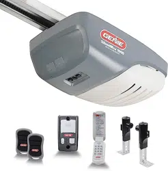
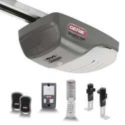
BELT/CHAIN DRIVE GARAGE DOOR OPENERS
PROGRAMMING, OPERATION, & MAINTENANCE MANUAL
42598.02135 10/2024
SERIAL NUMBER DECAL
STOP
DO NOT return product to store,
visit www.geniecompany.com
or call Customer Service at: 1-800-35-GENIE
iDCM SERIAL NUMBER DECAL
DO NOT use photocells from other manufacturers or openers with this opener.
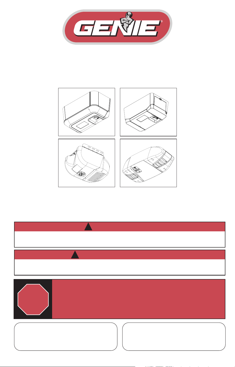
Images are for illustration purposes only, Your model may have dierent covers,
lenses, or accessories.
To reduce the risk of injury to persons or damage to property, use this opener only with a sectional residential
door.
WARNING
!
Por reduire le risque de blessures ou de dommages materials, utillsez cet ouvre-porte uniquement pour une
porte a section residentiel.
AVERTISSEMENT
!
Safety & General Information
Introduction .............................................................. 1
Safety Notications ................................................. 2
Important Installation Instructions ................... 3
Coin-Cell Battery Safety Warnings ..................... 4
Basic Wiring .................................................5
Programming Information
Introduction to opener programming ............ 6
Setting the DOWN Limit ....................................... 7
Setting the UP Limit ............................................... 8
Setting the Force Control ..................................... 9
Contact Reverse Test .............................................. 9
Contact Reverse Adjustment .............................. 9
Remote Control Programming ......................... 10
Wireless Wall Console Install & Prog* .............11
Keypad Programming* ........................................12
Homelink & Car2U Programming* ..................13
Aladdin Connect® Set up ............................. 14-15
Special Installation Information
Force Adjustment Guide .....................................16
Clearing Remote Memory .................................. 17
Tube Rail Adjustments .........................................17
Location of Safe-T-Beam® Pairs .........................18
Safe-T-Beam Troubleshooting ..........................18
Installing Battery Backup (BBU) ........................19
Maintenance
Important Safety Instructions ...........................20
Regular Maintenance Schedule .......................21
Door Inspection & Maintenance ...................... 21
Carriage Adjustment
(Release/Engagement ......................................21
Remote Battery Replacement ...........................22
Light Bulb Replacement .....................................22
Troubleshooting & LED Signals............. 23-24
Replacement Parts & Assemblies ......... 25-28
DASMA Safety Guidelines ........................ 29-30
1
2
3
4
5
6
7
8
INDEXINDEX
SAVE THESE INSTRUCTIONS
READ AND FOLLOW ALL INSTRUCTIONS
FCC Part 15.21 Statement:
Changes or modications not expressly
approved by the party responsible for
compliance could void the user’s authority
to operate the equipment.
FCC / IC Statement:
This device complies with FCC Part 15
and Industry Canada licence-exempt
RSS standard(s). Operation is subject
to the following two conditions: (1)
this device may not cause harmful
interference, and (2) this device must
accept any interference received, including
interference that may cause undesired
operation of the device.
Le présent appareil est conforme aux
CNR d’Industrie Canada applicables
aux appareils radio exempts de licence.
L’exploitation est autorisée aux deux
conditions suivantes : (1) l’appareil ne
doit pas produire de brouillage, et (2)
l’utilisateur de l’appareil doit accepter
tout brouillage radioélectrique subi,
même si le brouillage est susceptible d’en
compromettre le fonctionnement.
* Abbreviated versions. See instructions that
accompany the accessory or vehicle owners manual
for full details and instructions.
The Genie Company
One Door Drive
Mt. Hope, OH 44660, USA
1-800-35-GENIE (354-3643)
www.geniecompany.com
Patent listing at www.geniecompany.com/patents

1
DO NOT RETURN PRODUCT TO STOREDO NOT RETURN PRODUCT TO STORE
If you require assistance or have any
questions, a knowledgeable Genie Service
Technician is just a phone call away at:
1-800-35-GENIE (1-800-354-3643)
Or visit our website at:
www.geniecompany.com
Thank you for purchasing a Genie® brand garage door
opener. Genie® is the leader in garage door opener
technology.
Before setting up your new garage door opener, please note the model plate on the opener and
serial number(s) located on the front of this manual. This information will be necessary should
you seek technical support via our website, customer support department or local servicing
Genie dealer.
Please note that this manual covers several dierent models of
Genie® brand garage door openers. Illustrations contained in this
manual may not reect the exact model purchased. Skip steps or
pages that do not apply to your specic model. Programming and
installation of the opener and accessories are identical even though
they may appear dierently.
All external accessories shown in this manual are available for
purchase separately from your local Genie® retailer.
Read and understand all SAFETY WARNINGSSAFETY WARNINGS and CAUTIONSCAUTIONS
contained in this manual before proceeding.
©2024 GMI Holdings, Inc d/b/a The Genie Company, the Genie logo, Intellicode, Safe-T-Reverse, SmartSet,
Sure-Lock, Door Detect, and Safe-T-Beam, Aladdin Connect, iDCM, are trademarks of The Genie Company.
All other trademarks are property of their rightful owners. Consistent with our policy of continuing product
improvements, we reserve the right to change product specications without prior notice or obligations.
HomeLink is a registered trademark of Gentex Corporation. Car2U is a registered trademark of Lear
Corporation.
INTRODUCTIONINTRODUCTION
1
Spanish language manuals available at:
Idioma alternativo manuales disponibles en:
www.geniecompany.com
}
2
DANGER POTENTIEL EFFET PRÉVENTION
PORTE EN MOUVEMENT
AVERTISSEMENT
Pourrait entraîner des
blessures graves voire la
mort
Utiliser uniquement si la porte est en vue et libre de tout obstacle. Ne
laisser personne se tenir dans l’ouverture de la porte pendant qu’elle est
en mouvement.
NE PAS permettre aux enfants de jouer avec l’opérateur de la porte.
NE PAS modier la commande de l’opérateur à contact momentané à
moins qu’un moyen d’inversion externe soit installé.
NE PAS faire fonctionner une porte qui bloque ou dont le ressort est cassé.
CHOC ÉLECTRIQUE
AVERTISSEMENT
Pourrait entraîner des
blessures graves voire la
mort
Couper le courant avant d’enlever le couvercle de l’opérateur.
Lorsque le couvercle doit être remplacé, s’assurer que les ls ne
sont ni coincés ni près des pièces mobiles.
L’opérateur doit être correctement mis à la terre.
TENSION ÉLEVÉE RESSORT
AVERTISSEMENT
Pourrait entraîner des
blessures graves voire la
mort
NE PAS essayer d’enlever, réparer ni ajuster les ressorts ou
toute autre pièce à laquelle le ressort de la porte est attaché, y
compris blocs de bois, supports en acier, câbles ou autres articles
semblables.
Les réparations et les réglages doivent être eectués par
technicien qualié qui se sert d’outils appropriés et qui respecte
les instructions.
!
!
!
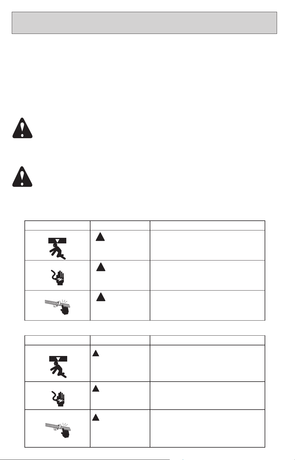
OVERVIEW OF POTENTIAL HAZARDS
READ THIS SAFETY INFORMATION
Garage doors are large, heavy objects that move with the help of springs under high tension and electric motors. Since moving objects, springs
under tension, and electric motors can cause injuries, your safety and the safety of others depend on you reading the information in this manual.
If you have questions or do not understand the information presented, call your nearest trained door system technician or visit our website at
www.geniecompany.com.
CONVENTIONS USED IN THESE INSTRUCTIONS
The following safety alert symbol and signal words are used throughout this manual to call attention to and identify dierent levels of hazards
and special instructions.
This is the safety alert symbol. This symbol alerts you to potential hazards that can kill or hurt you and others. All safety messages will follow the
safety alert symbol and the word
“DANGER”, “WARNING”,
or
“CAUTION”.
•
DANGER
indicates an imminently hazardous situation which, if NOT avoided, will result in death or serious injury.
•
WARNING
indicates a potentially hazardous situation which, if NOT avoided, could result in death or serious injury.
•
CAUTION
indicates a potentially hazardous situation which, if NOT avoided, may result in injury or property damage.
•
The word
NOTE
i
s used to indicate important steps to be followed or important considerations.
Tous les messages concernant la sécurité seront indiqués après un symbole d’alerte de la sécurité et l’une des mentions suivantes “DANGER”,
”AVERTISSEMENT” ou “MISE EN GARDE”.
• DANGER signale une situation dangereuse imminente qui, si elle n’est pas évitée, risque d’entraîner des blessures graves, voire
mortelles.
• AVERTISSEMENT signale une situation potentiellement dangereuse qui, si elle n’est pas évitée, risque d’entraîner la mort ou des
blessures graves.
• MISE EN GARDE signale une situation potentiellement dangereuse qui, si elle n’est pas évitée, risque d’entraîner des blessures ou
des dommages matériels.
• Le terme REMARQUE est utilisé pour signaler les étapes importantes à suivre ou d’importants éléments à prendre en
considération.
SAFETY NOTIFICATIONS & INSTRUCTIONSSAFETY NOTIFICATIONS & INSTRUCTIONS
IMPORTANT SAFETY INSTRUCTIONS
IMPORTANTES CONSIGNES DE SÉCURITÉ
POTENTIAL HAZARD EFFECT PREVENTION
MOVING DOOR
WARNING
Could result in Serious
Injury of Death
DO NOT operate unless the doorway is in sight and free of
obstructions. Keep people clear of opening while door is moving.
DO NOT allow children to play with the door opener.
DO NOT change opener control to momentary contact unless an
external reversing means is installed.
DO NOT operate a door that jams or one that has a broken spring.
ELECTRICAL SHOCK
WARNING
Could cause Serious
Injury or Death
Turn o electrical power before removing opener cover.
When replacing the cover, make sure wires are not pinched or near
moving parts.
Opener must be electrically grounded.
HIGH SPRING TENSION
WARNING
Could cause Serious
Injury or Death
DO NOT try to remove, repair or adjust springs or anything to which
door spring parts are fastened such as wood block, steel brackets,
cables or any other structure or like item.
Repairs and adjustments must be made by a trained service
representative using proper tools and instructions.
!
!
!
3
IMPORTANT INSTALLATION INSTRUCTIONS
IMPORTANTES INSTRUCTIONS D’INSTALLATION
WARNING
!
Opener is equipped with grounded electrical plug for
your protection, and only ts grounded electrical
outlets. DO NOT alter plug in any way! If your have no
grounded outlets, have one installed by a licensed
electrician. Opener must be properly grounded to prevent
personal injury and equipment damage. NEVER USE AN
EXTENSION CORD! Check local building codes for any
requirement that you must have a permanent hard-wired
connection. Permanent hard-wired connections must be
performed by a licensed electrician using proper tools and
instructions.
AVERTISSEMENT
!
L’opérateur, qui est équipé d’une prise électrique
mise à la terre pour votre protection est compatible
uniquement avec des prises électriques mises à
la terre. NE PAS modier la che dune quelconque
manière. Si vous n’avez pas de prises mises à la terre,
faites-en installer par un électricien agréé. L’opérateur
doit être correctement mis à la terre pour éviter les
blessures corporelles et des dommages matériels.
NE JAMAIS UTILISER DE RALLONGE! Vériez les
codes locaux des bâtiments pour connexions câblées
permanente. Les connexions câblées permanentes
doivent être eectuées par un électricien agréé qui se
servira d’outils appropriés et respectera les consignes.
WARNING
!
TO REDUCE THE RISK OF SEVERE INJURY OR
DEATH
READ AND FOLLOW ALL SAFETY, INSTALLATION AND OPERATION INSTRUCTIONS. If you have any questions or do
not understand an instruction, call The Genie Company.
• DO NOT install opener on an improperly balanced door. An improperly balanced door could cause severe injury.
Repairs and adjustments to cables, spring assembly and other hardware must be made by a trained service person
using proper tools and instructions.
• Remove all ropes, and disable all locks connected to the door before installing opener.
• Where possible, install the door opener 7 feet or more above the oor. For products having an emergency release,
mount the emergency release within reach, but at least 6 feet above the oor and avoiding contact with vehicles to
avoid accidental release. DO NOT use emergency release cord to pull door.
• DO NOT connect the opener to the source of power until instructed to do so.
• Locate the wall control button: A) Within sight of door. B) At a minimum height of 5 feet, so small children cannot
reach it. C) Away from all moving parts of the door.
• Install the entrapment WARNING label next to the wall button or console, in a prominent location. Install the
emergency release handle on the emergency release cord.
• The opener must reverse when the door contacts a 1-1/2 inch high object on the oor at the center of the doorway.
This is about the size of a 2” x 4” board laid at.
AVERTISSEMENT
!
POUR RÉDUIRE LES RISQUES DE BLESSURES GRAVES
VOIRE MORTELLES
LIRE ET SUIVRE ATTENTIVEMENT TOUTES LES INSTRUCTIONS D’INSTALLATION ET DE FONCTIONNEMENT AINSI QUE TOUTES LES
CONSIGNES DE SÉCURITÉ. Si vous avez des questions ou si vous ne comprenez pas une instruction, veuillez contacter directement The
Genie Company.
• NE PAS installer l’opérateur sur une porte mal équilibrée. Celle-ci pourrait entraîner de graves blessures. Les répa-
rations et les réglages des câbles, ensembles de ressort ou tout autre article de quincaillerie doivent être eectués
par un professionnel qui se sert d’outils appropriés et qui respecte les instructions.
• Enlever toutes les cordes et désactiver toutes les verrous de la porte avant l’installer l’opérateur.
• Dans la mesure du possible, installer l’ouvre-porte à 2,1 m ou plus au-dessus du sol. Pour les produits dotés d’un
cordon de déclenchement d’urgence, installer le déclenchement d’urgence mais au moins à 1,8 m au-dessus du sol
en évitant tout contact avec les véhicules pour éviter qu’ils ne soient déclenchés accidentellement. NE PAS utiliser
d’urgence cordon de libération pour ouvrir ou fermer la porte.
• NE PAS connecter l’opérateur à la source d’alimentation tant que l’instruction n’est pas donnée.
• Repérer la console murale: A) En vue de la porte. B) À une hauteur minimale de 1,5 m an que les jeunes enfants ne
puissent pas l’atteindre. C) Loin de toutes pièces mobiles de la porte du garage.
• Placer l’étiquette d’AVERTISSEMENT en cas de coinçage à proximité du bouton mural ou de la console de manière à
ce qu’elle soit bien en évidence. Installer la poignée du cordon de déclenchement d’urgence.
• L’opérateur doit s’inverser lorsque la porte entre en contact avec un objet d’une hauteur de 3,8 cm placé sur le sol,
au centre de l’ouverture de la porte. Ceci équivaut environ à une planche de 5 x 10 cm posée à plat sur le sol.
4
COIN-CELL BATTERY SAFETY WARNINGSCOIN-CELL BATTERY SAFETY WARNINGS
• Remove and immediately recycle or dispose of used batteries according to local regulations
and keep away from children.
DO NOT dispose of batteries in household trash or incinerate.
• Even used batteries may cause severe injury or death.
• Call a local poison control center for treatment information.
• Replace only with Type CR2032 3V batteries.
• Non-rechargeable batteries are not to be recharged.
• DO NOT force discharge, recharge, disassemble, heat above (manufacturer’s specied
temperature rating) or incinerate. Doing so may result in injury due to venting, leakage or
explosion resulting in chemical burns.
• Ensure the batteries are installed correctly according to polarity (+ and -).
• DO NOT mix old and new batteries, dierent brands or types of batteries, such as alkaline,
carbon-zinc, or rechargeable batteries.
• Remove and immediately recycle or dispose of batteries from equipment not used for an
extended period of time according to local regulations.
• Always completely secure the battery compartment. If the battery compartment does not
close securely, stop using the product, remove the batteries, and keep them away from
children.
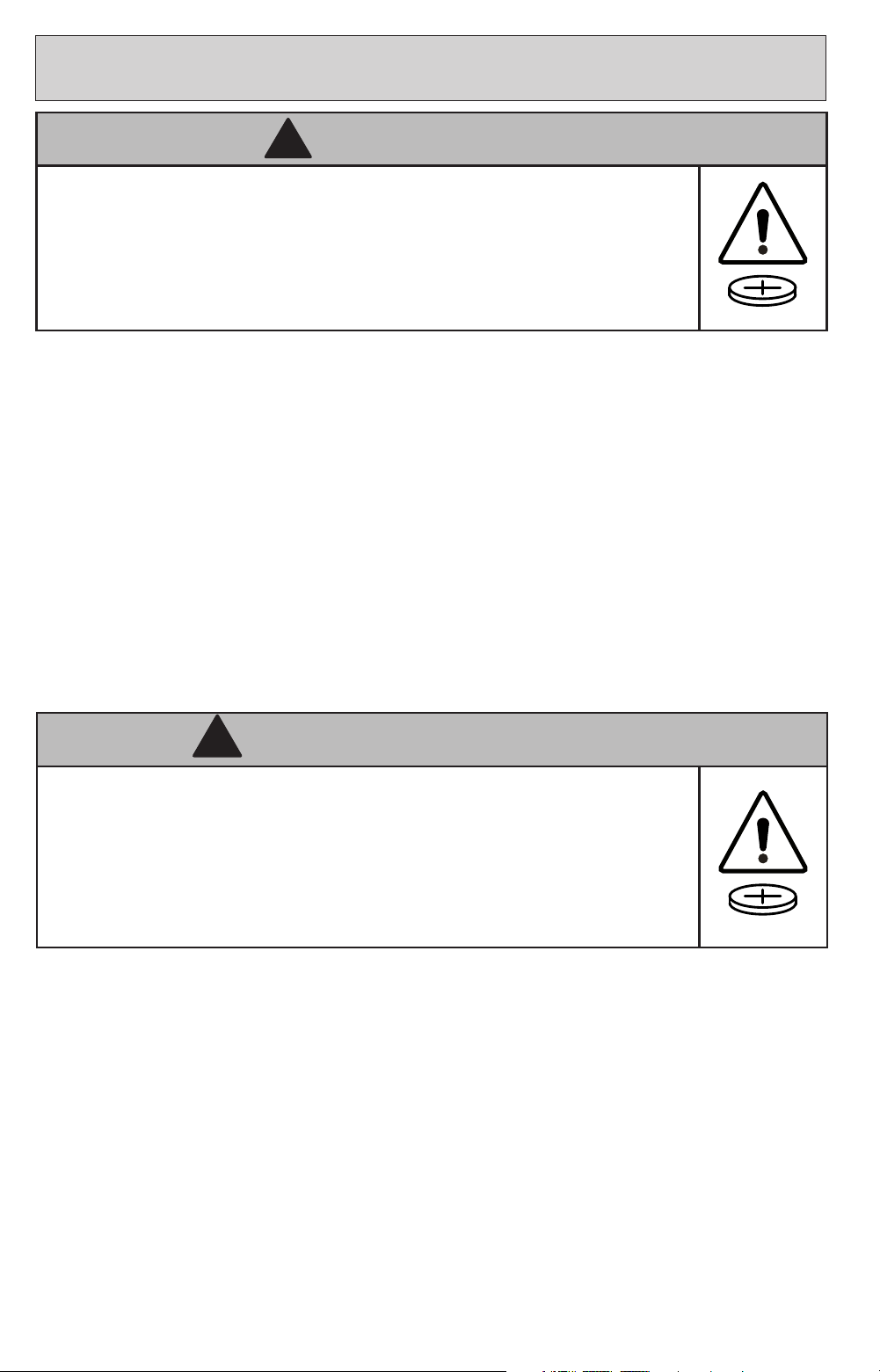
• INGESTION HAZARD: this product contains a button cell or coin battery.
• DEATH or serious injury can occur if ingested.
• A swallowed button cell or coin battery can cause Internal Chemical Burns in
as little as 2 hours.
• KEEP new and used batteries OUT OF REACH OF CHILDREN
• Seek immediate medical attention if a battery is suspected to be swallowed
or inserted inside any part of the body.
WARNING
!
AVERTISSEMENT
!
• DANGER D’INGESTION : Ce produit contient une pile bouton ou une pile
bouton.
• La MORT ou des blessures graves peuvent survenir en cas d’ingestion.
• Une pile bouton ou une pile bouton avalée peut provoquer des dommages
chimiques internes brûle en seulement 2 heures.
• GARDER les piles neuves et usagées HORS DE LA PORTÉE DES ENFANTS
• Consultez immédiatement un médecin si vous soupçonnez qu’une batterie
est avalé ou inséré dans n’importe quelle partie du corps.
• Retirez et recyclez ou jetez immédiatement les piles usagées conformément aux
réglementations locales et gardez-les hors de portée des enfants. Ne jetez PAS les piles avec
les ordures ménagères ou ne les incinérez pas.
• Même les piles usagées peuvent provoquer des blessures graves, voire la mort.
• Appelez un centre antipoison local pour obtenir des informations sur le traitement.
• Remplacez uniquement par des piles de type CR2032 3 V.
• Les piles non rechargeables ne doivent pas être rechargées.
• Ne forcez pas la décharge, la recharge, le démontage, la chaleur au-dessus de la température
nominale spéciée par le fabricant et l’incinération. Cela pourrait entraîner des blessures dues
à une ventilation, une fuite ou une explosion entraînant des brûlures chimiques.
• Assurez-vous que les piles sont installées correctement selon la polarité (+ et -).
• Ne mélangez pas des piles anciennes et neuves, des marques ou des types de piles diérents,
tels que des piles alcalines, carbone-zinc ou rechargeables.
• Retirez et recyclez ou jetez immédiatement les batteries des équipements non utilisés
pendant une période prolongée, conformément aux réglementations locales.
• Sécurisez toujours complètement le compartiment à piles. Si le compartiment des piles ne
se ferme pas correctement, arrêtez d’utiliser le produit, retirez les piles et gardez-les hors de
portée des enfants.
5
BASIC WIRINGBASIC WIRING
2
CAUTION
When using insulated staples, make only snug enough to hold
electrical wire in place. Staples too tight can cause damage to
wire and cause Safe-T-Beam
®
System to malfunction.
!
WARNING
Use of any other wall control can cause unexpected operation
of the door and loss of lighting feature. Locate wall console
within sight of door and far enough from door to prevent
contacting it while operating the console. Control must be
at least 5 feet above oor to prevent small children from
operating it.
!
Lors de l’utilisation des agrafes isolées, serrez susamment
pour tenir le l en place mais sans plus. Si vous serrez trop,
vous risquez d’endommager les ls et de provoquer le
dysfonctionnement du système Safe-T-Beam®.
CAUTION
!
AVERTISSEMENT
!
L’utilisation d’une autre commande murale pourrait produire des
résultats inattendus de la porte ainsi que le dysfonctionnement
de l’éclairage. Localisez la console murale en vue de la porte et
susamment loin de la porte pour éviter tout contact pendant
l’utilisation de la console. La commande doit être à une hauteur
minimale de 1,5 m au-dessus du sol an que les jeunes enfants ne
puissent pas l’atteindre.
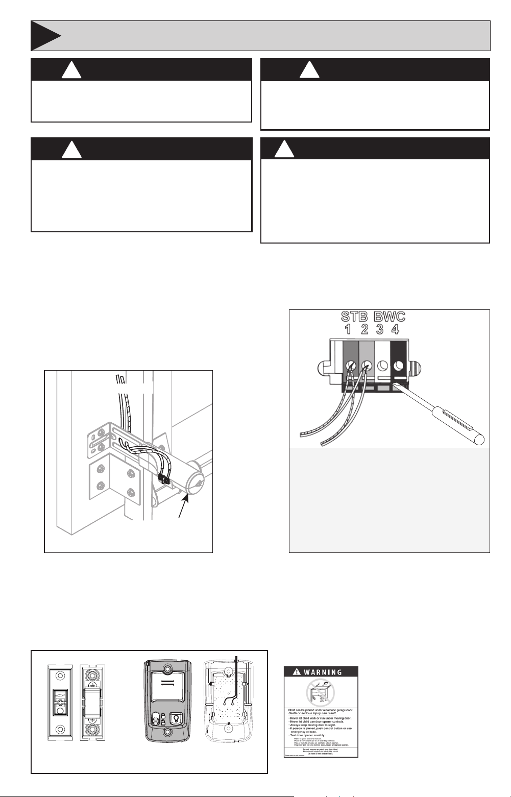
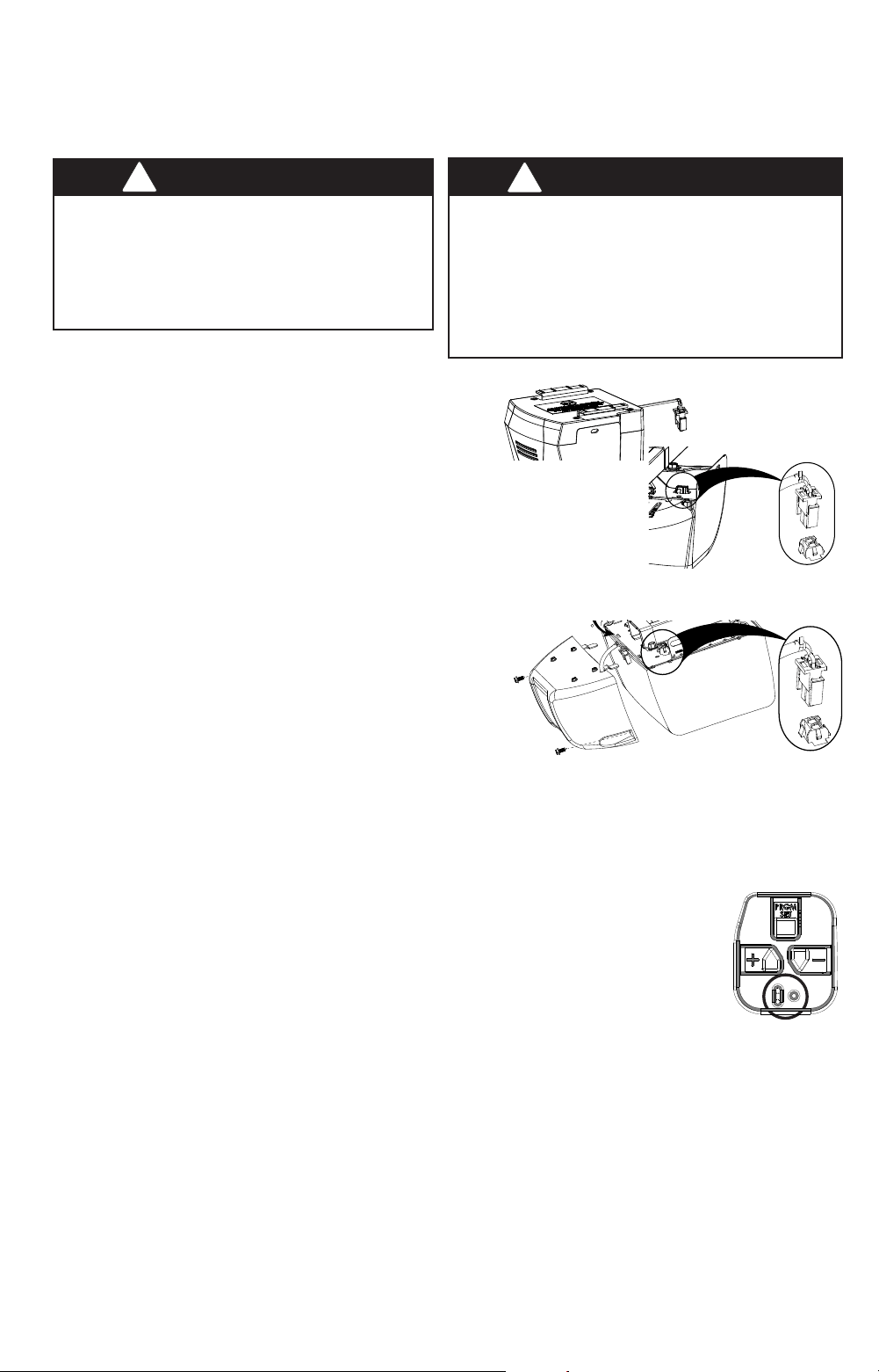
SAFE-T-BEAM WIRES:
Striped Wires to Terminal 1
White Wires to Terminal 2
WALL CONSOLE WIRES:
White Wire to Terminal 3
Striped Wire to Terminal 4
Push in on Tabs to Insert Wire
Transmitter/Receiver
To powerhead
Use the following as a basic wiring guide. If you require professional assistance with the
physical assembly or installation of a complete opener, please contact your local Genie dealer
or call us at 1-800-35-GENIE for guidance.
Safe-T-Beam Sensors
For each sensor, remove ¼” insulation from the
white and striped wires and secure the wire
under each screw terminal. See the graphic at
right for connection to powerhead.
B/W W
Striped Wire to B/W Terminal
White Wire to W Terminal
Wall Console
Remove ¼” insulation from the white and striped wires and secure white to the “W” (-) terminal
and striped to the “B” or “B/W” (+) terminal as shown. Post an ENTRAPMENT WARNING LABEL
(varies by model) next to the console. See above for connection to powerhead. (If you have a
wireless console, review its section of the manual). One wired lighted wall console per opener,
and additional wired, non-lighted push buttons can be used.
Mount sensor 5-6” above oor
6
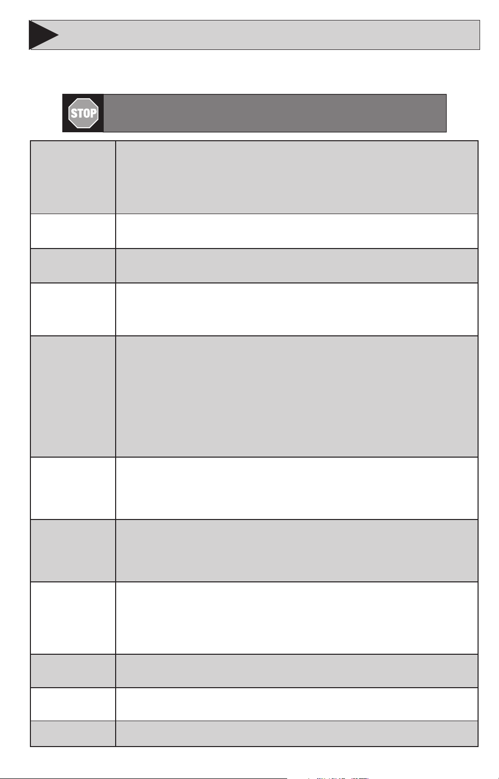
Term Denitions:
Travel Limits Programmable setting to adjust how far door travels up or down.
Force Control refers to how much power is needed to move (open/close) a particular door and
will initially be set with the rst full cycle of the door.
Remote & Accessory Programming synchronizes remote devices with the powerhead.
(Remote Controls, Aladdin Connect®, Wireless Keypad, Vehicle Remote Systems)
NOTE:
Each programming step has a 30 second time limit for completion after the function is initiated. After 30 seconds, both
LED’s will illuminate RED indicating time has expired and the step must be restarted. Restart the step as many times as necessary
to complete the programming.
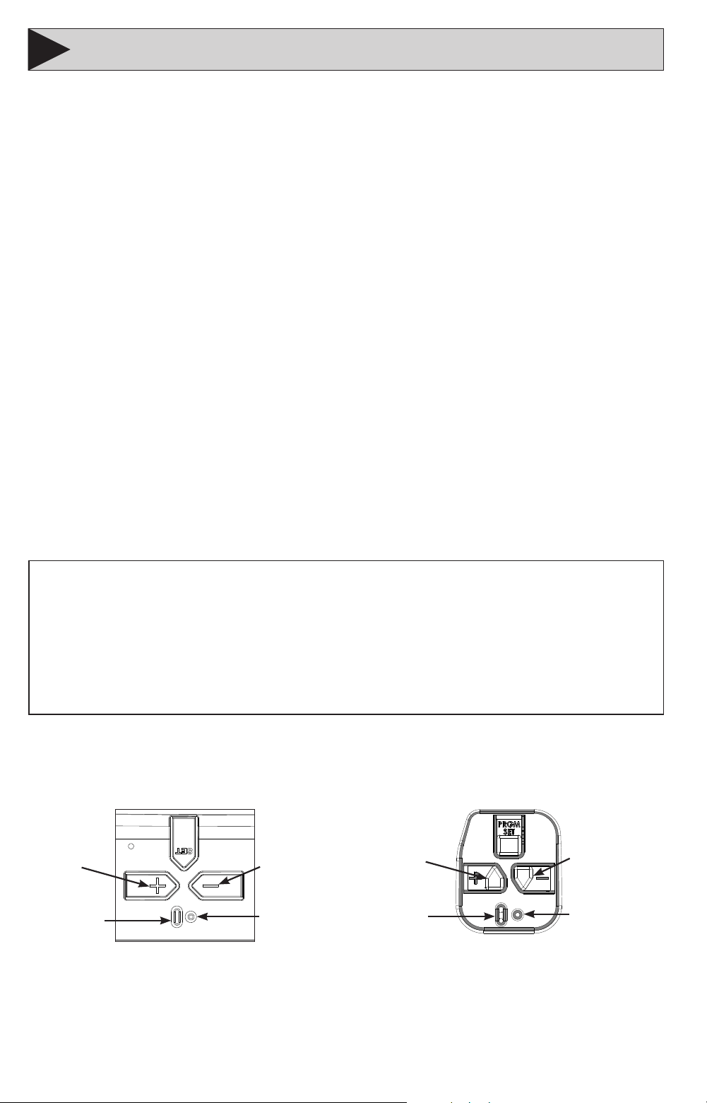
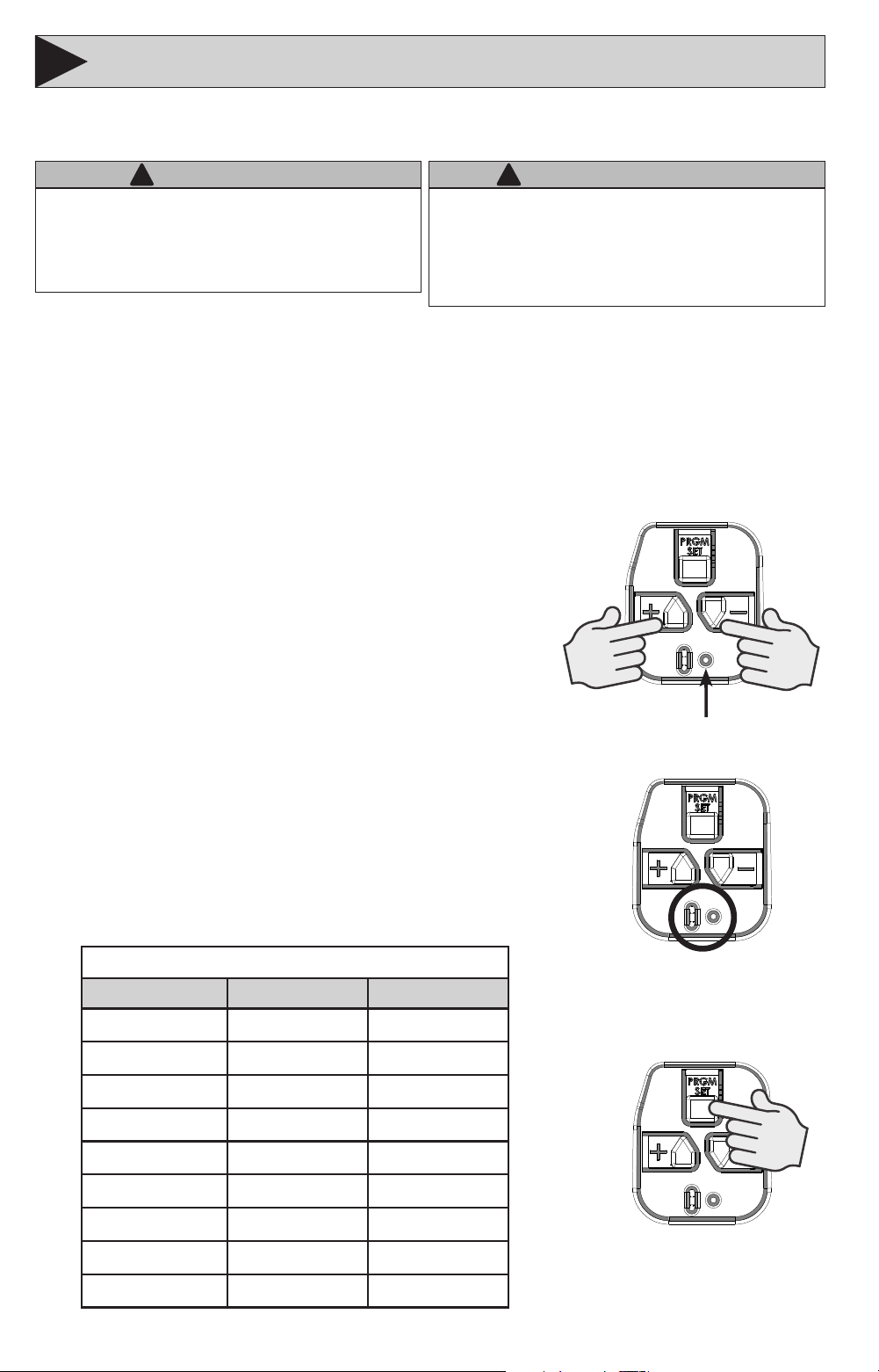
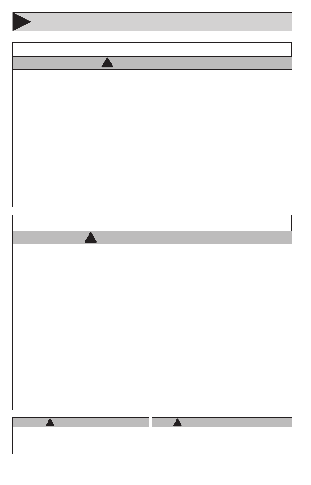
Long LED
Indicator
Round LED
Indicator
Program/Set
Open Travel
Button
Close Travel
Button
Programming Button Layouts (Vary by Models)
NOTE:
Before programming the opener, check to make sure there are no objects in the garage door
opening. DO NOT allow persons to enter the area of the door while programming and operating.
Please note that this manual covers several dierent models of Genie® brand garage door
openers. Illustrations contained in this manual may not reect the exact model purchased. Skip
steps or pages that do not apply to your specic model. Programming and installation of the
opener and accessories are identical even though they may appear dierently.
The following steps list the order of programming the opener’s functional settings and install any
accessories that were included with the opener or purchased separately. These steps should be
performed in order.
1. Down travel limit
2. Up travel limit
3. Force control
4. Contact reverse test and adjustment
5. Remote control programming
• Remote control(s) included with this opener are programmed at the factory.
6. Accessory programming :
• Install and program wireless wall console (if equipped)
• Program wireless keypad (if applicable)
• Program built in vehicle remote (if applicable)
• Program the integrated Aladdin Connect if equipped
7. Install battery backup (if equipped)
OPENER PROGRAMMING & ACCESSORY INSTALLATIONSOPENER PROGRAMMING & ACCESSORY INSTALLATIONS
3
Long LED
Indicator
Round LED
Indicator
Program/Set
Open Travel
Button
Close Travel
Button
7
WARNING
!
• Make sure doorway is in full view and clear of obstacles and
people to avoid injury or property damage.
• DO NOT operate this unit from the wall control before LIMITS
are set. Severe damage to the opener could occur.
• The carriage MUST be engaged to turnbuckle BEFORE setting
limits. See installation poster or call Customer Service at
1-800-35-GENIE or visit www.geniecompany.com.
• DO NOT set limits with Battery Backup attached. AC power
MUST be connected to the opener while setting limits for
proper operation.
AVERTISSEMENT
!
• S’assurer que le passage de la porte est visible et dégagé, à
savoir sans obstacles ni personne an d’éviter toute blessure
potentielle ou dommage matériel.
• NE PAS utiliser cette unité avec la console murale avant d’avoir
réglé les LIMITES. L’ouvre-porte pourrait subir de sérieux
dommages.
• La tendeur DOIT être engagée dans le chariot AVANT de régler
les limites. Voir le poster d’installation (si fourni) ou appelez
le service clientèle au 1-800-35-GENIE ou visitez le site www.
geniecompany.com.
• NE PAS xer de limites en mode batterie de secours.
L’alimentation CA DOIT être branchée sur l’ouvre-porte, pendant
le réglage des limites, pour assurer un bon fonctionnement.
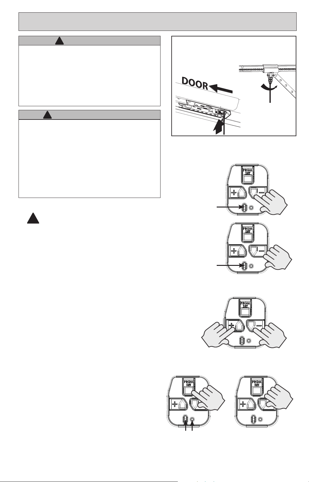
1. Press and hold the DOWN arrow button.
• Long LED will light BLUE.
2. Release DOWN arrow button.
• Long LED will ash BLUE.
3. Press and hold the DOWN arrow button until
door is fully closed.
• Use the UP arrow button if door closes too
far. Use both UP and DOWN buttons to
adjust close travel as necessary.
Door should rest on the oor until the weather strip
is compressed enough to seal along the width of
the door. Damaged doors or uneven oors may not
seal properly. Repair these conditions to achieve a
proper seal. DO NOT compress seal so much that the
door will bend or buckle.
4. Press and release the PRGM/SET button
• Both LEDs will ash BLUE then go out.
The DOWN limit is now programmed.
Steady Blue
HOLD
UNTIL
LED
Lights
Flashing Blue
RELEASE
1-2. Enter Programming Mode
3. Adjust Door Position
Programming DOWN Limit:
NOTE:
Carriage should be locked to
opener. Door should rest somewhere between full
open and closed. Do not start with door fully open
or closed.
4. Lock Programming
Flashing Blue
PRESS
&
RELEASE
SETTING DOWN TRAVEL LIMITSETTING DOWN TRAVEL LIMIT
!
Lever must be UP
CHANNEL
MODELS
TO ENGAGE DOOR TO CARRIAGE:
Lift door by hand until carriage engages the
bullet on the chain/belt systems.
Lever must be UP
TUBE RAIL
MODELS
8
SETTING UP TRAVEL LIMITSETTING UP TRAVEL LIMIT
Steady Blue
HOLD
UNTIL
LED
Lights
Flashing Blue
RELEASE
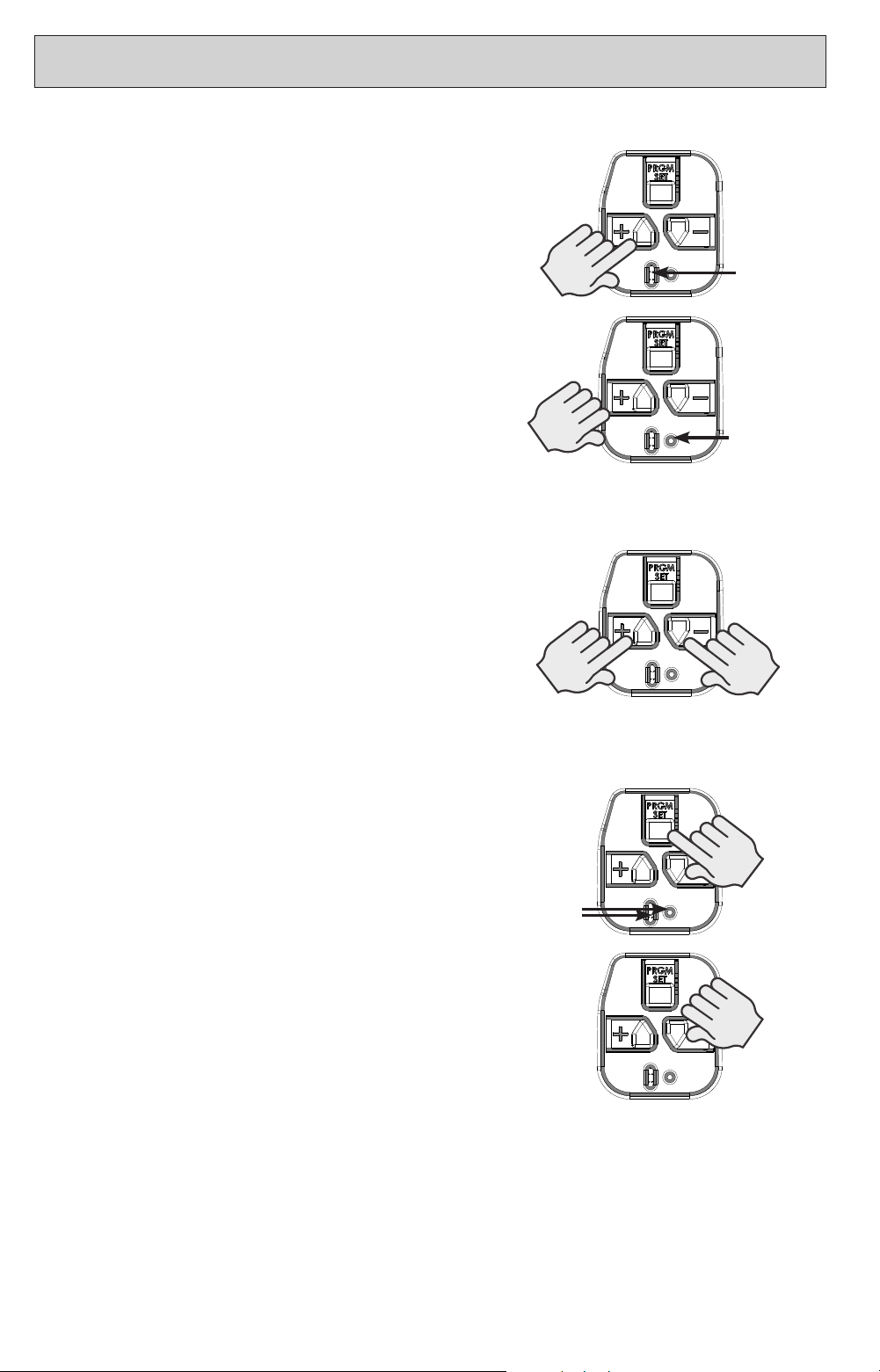
1-2. Enter Programming Mode
3. Adjust Door Position
4. Lock Programming
Flashing Blue
PRESS
&
RELEASE
1. Press and hold the UP arrow button.
• Long LED will light BLUE.
2. Release UP arrow button.
• Round LED will ash BLUE.
3. Press and hold the UP arrow button until door
is fully open.
• Use the DOWN arrow button if door opens
too far. Use both UP and DOWN buttons to
adjust open travel as necessary.
Door should fully open so that door seal is even with
door header. Do Not adjust so much that the door
will bend or buckle or stretch door spring cables
backward.
4. Press and release the PRGM/SET button
• Both LEDs will ash BLUE then go out.
The UP limit is now programmed.
Programming UP Limit:
9
SETTING FORCE AND CONTACT REVERSESETTING FORCE AND CONTACT REVERSE
Force Control
The force controls are automatically set when the
wall control is used for the rst time with garage door
opener. The door MUST complete one full cycle, from
full open to full close and then, full close to full open,
before the settings are automatically recorded.
Contact Reverse Test
NOTE:
The limit and Force settings MUST BE
COMPLETED before performing the Contact Reverse Test.
Force Control Adjustments
Force settings are programmed from the factory
to remain within safe parameters. These should
not require adjustments. However, certain
circumstances may require adjustment.
Refer to the “SPECIAL INSTALLATION
INFORMATION” section to adjust the force settings.
WARNING
!
TO AVOID INJURY OR DAMAGE
• NEVER adjust the force settings to adjust for damage,
including an unbalanced door, binding door track or
broken spring.
• Perform a CONTACT REVERSE TEST monthly.
AVERTISSEMENT
!
Pour éviter les blessures ou des dommages
• NE JAMAIS régler la force pour compenser des
dommages, y compris une porte mal équilibrée, un rail de
porte coinçant ou des ressorts cassés.
• Tous les mois, EFFECTUEZ LE TEST D’INVERSION AU
CONTACT.
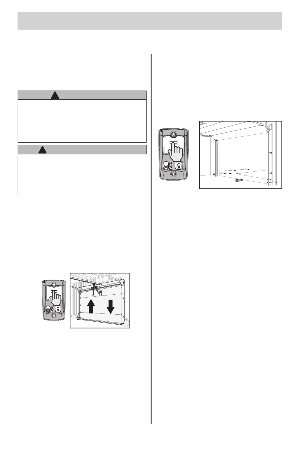
1. Press and release the Wall Control button
and allow the garage door to travel and
stop at the DOWN limit.
2. Press and release the wall control button
and allow the garage door to travel and
stop at the UP limit.
1. With the garage door open, lay a 2 X 4
board at on the oor at the center of the
door opening.
2. Close the garage door using the wall
control.
• When the door contacts the board, it should
stop and reverse direction within 2 seconds
to the full open position.
• The long LED light on the powerhead will
begin to ash RED with the reversal of the
door.
• Remove the 2” x 4” board and operate the
opener with the wall control again. This cycle
will clear the ashing red LEDs.
Contact Reverse Adjustment
If the door stops before contacting the board
or if it does not reverse direction to fully open
after contact with the board, it may be due to an
improperly set DOWN limit. Verify settings by:
1. Repeat the “Down Travel Limit” section to
make certain the door is closing tight against
the oor.
2. Repeat the “Force Control” section on the left
to set force limits.
3. Repeat the “Contact Reverse Test” above.
Repeat this process as needed until the door
passes the Contact Reverse Test.
Refer to the “SPECIAL INSTALLATION
INFORMATION” section to adjust the force
settings.
10
NOTE:
The following instructions are for remote control transmitters
purchased separately in addition to those provided with this opener,
but can also be used if any remote(s) may require re-programming.
NOTE:
Each programming step has a 30 second time limit for
completion after the function is initiated. After 30 seconds, two
LED’s will illuminate RED indicating time has expired and the step
must be re-started. Restart the step as many times as necessary
to complete the programming.
NOTE:
Do not hold remote too close to the powerhead when
programming remote buttons.
NOTE:
Each button on each remote must be programmed
separately, following these steps.
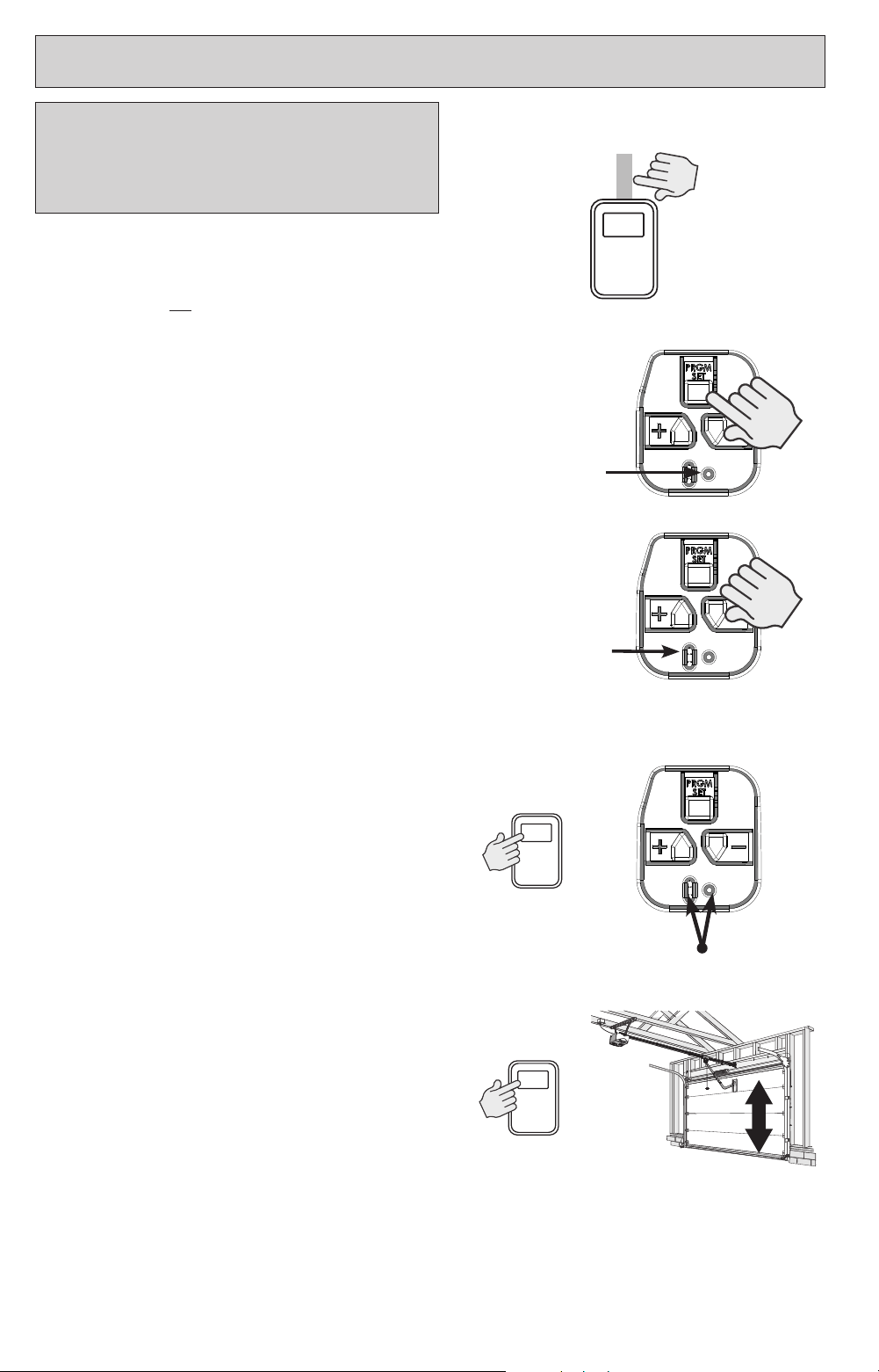
1. Remove the battery’s protective lm from the
remote by pulling straight down.
2. Press and hold the PRGM/SET button on the
opener for two seconds.
• The ROUND LED will turn BLUE.
• The LONG LED will then ash PURPLE.
3. Stand at least 5 feet away from opener and
slowly press and release the desired button on
the remote two times.
• Both opener LEDs will ash and turn
o indicating the remote has been
programmed.
4. Press the desired remote button again.
• The opener should run.
To program the same remote for other garage door
openers, repeat the steps above using one of the other
remaining remote buttons.
REPEAT STEPS 1 TO 4 FOR EACH OPENER AND
REMOTE
NOTE:
It is possible to press the remote button too quickly
or lightly. If the LEDs do not go o, press the remote button
several more times to achieve conrmation.
BASIC PROGRAMMING IS COMPLETE AND YOUR
GARAGE DOOR OPENER IS READY TO USE.
Refer to the “SPECIAL INSTALLATION INFORMATION”
section to
erase remote devices from memory.
Flashing
2. Enter Programming Mode
4. Test Remote
1. Activate Remote
Solid Blue
PRESS
&
RELEASE
Flashing Purple
3. Press Remote Button Twice
PROGRAM ADDITIONAL REMOTE CONTROLSPROGRAM ADDITIONAL REMOTE CONTROLS
THE REMOTE CONTROLS INCLUDED WITH THE REMOTE CONTROLS INCLUDED WITH
THIS OPENER MAY HAVE BEEN THIS OPENER MAY HAVE BEEN
PROGRAMMED AT THE FACTORY FOR YOUR PROGRAMMED AT THE FACTORY FOR YOUR
CONVENIENCE.CONVENIENCE.
11
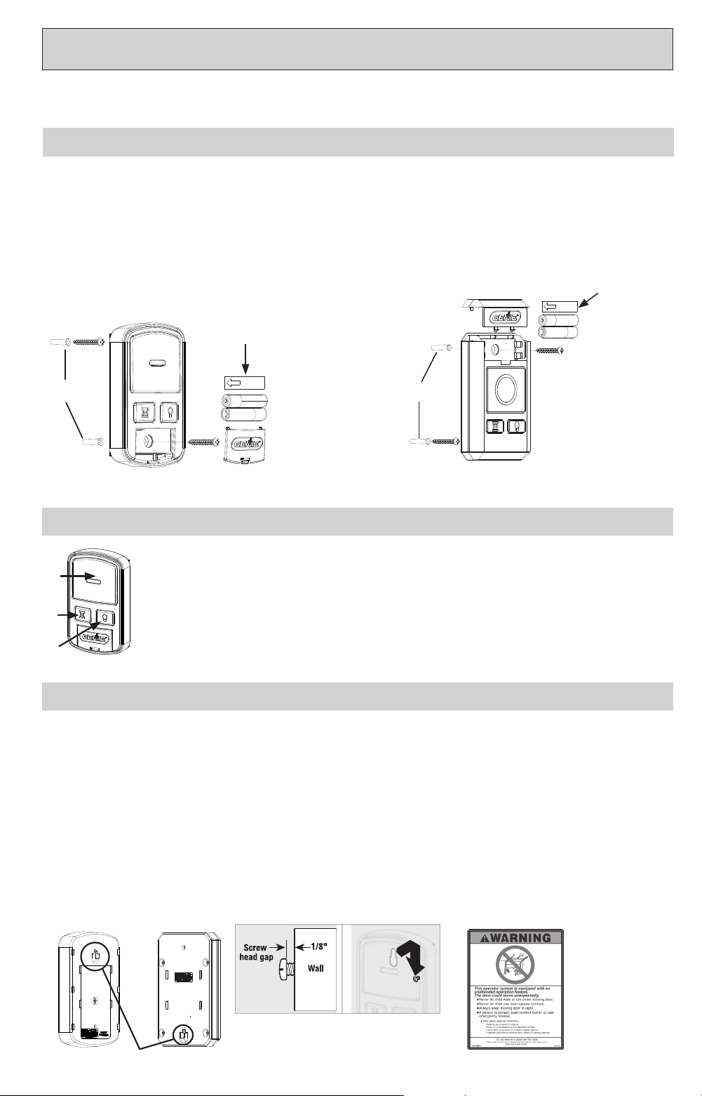
PROGRAM WIRELESS WALL CONSOLEPROGRAM WIRELESS WALL CONSOLE
Slotted Mount
AAA
AAA
Open cover and
remove battery
tab before
programming
Drywall
Anchors
Mounting
Screws
Open console cover and remove battery tab before programming.
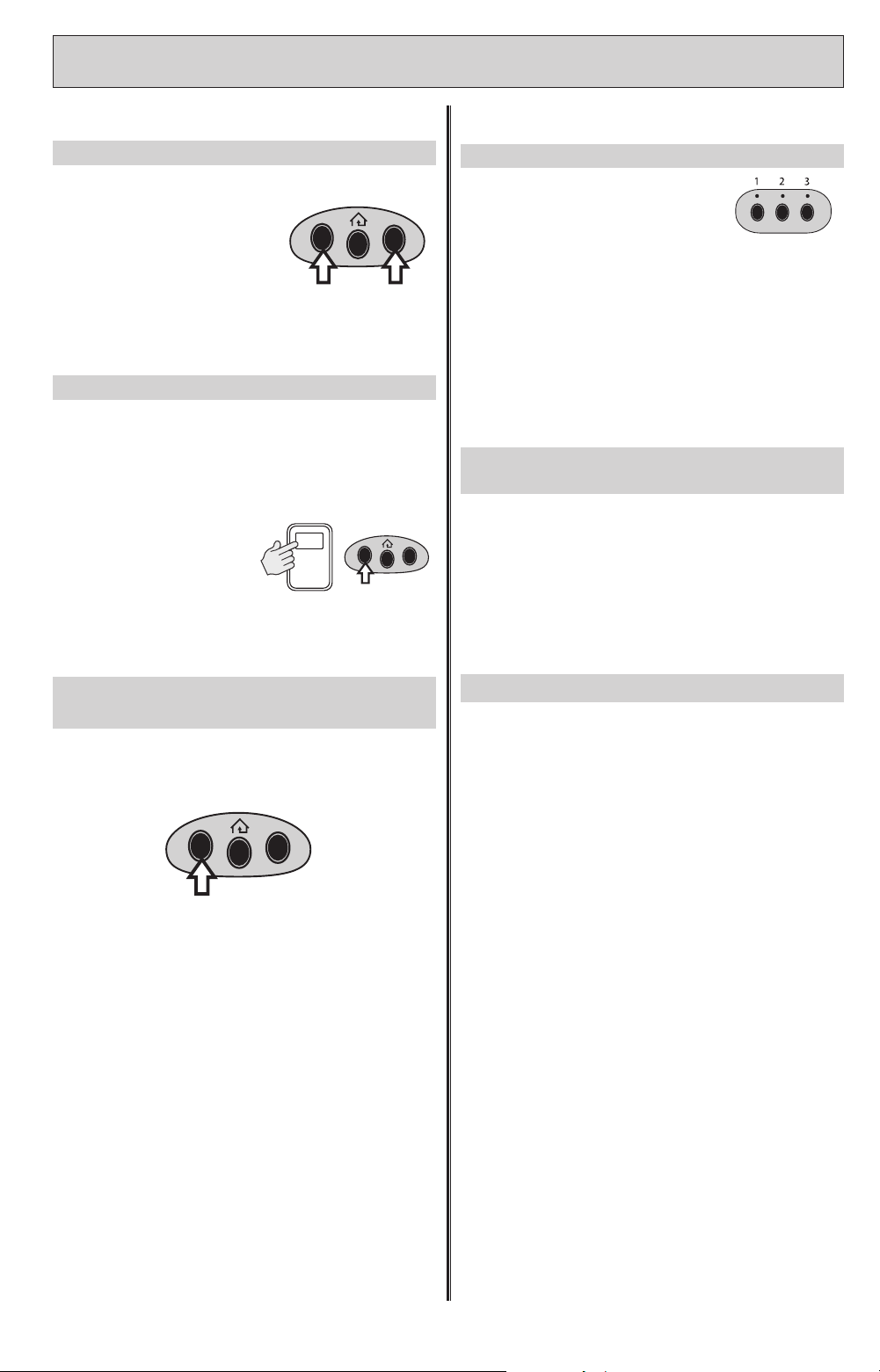
Place opener into remote control programming mode (SEE PAGE 10):
1. Press and hold the program button on the opener until the round LED turns blue, then release.
2. The round LED will go out and the long LED will begin ashing purple.
3. Press the DOOR button on the WALL CONSOLE 3 times or until door operates.
STEP 1) Program Wireless Wall Console to Garage Door Opener
1. DOOR Button - Runs garage door opener.
2. DELAY Button - Each press adds a 10 second delay for door operation (up to
3 times for up to 30 sec.). Press the delay button and door will automatically
operate after set delay.
3. LIGHT Button - Overrides the automatic timed light function of the garage
door opener.
1
2
3
STEP 2) Operating the Door with Wall Console
QuickView setup.
Please see complete instructions that accompany Wireless Wall Console
STEP 3) Mounting the Wall Console
The Wall Console MUST be mounted within sight of the garage door(s) at least ve feet above the oor and
clear of any moving door part. Use UNINTENDED OPERATION decal in lieu of standard console warning decal.
1. Remove battery cover and batteries.
2. Drill 3/32” pilot hole for the slotted mounting hole screw (included) or 5/32” if using drywall
anchors.
3. Install a screw into the pilot hole, leaving a 1/8” gap between the screw head and wall.
4. Hook the slotted mount, on back of console, over the screw.
5. Mark and drill a pilot hole for the screw under the battery cover (included) and secure console
to wall
6. Reinstall batteries and cover.
Apply
unintended
operation decal
next to wall
console.
Included with select models
AAA
AAA
Mounting
Screws
Drywall
Anchors
Open cover and
remove battery
tab before
programming
Retail Version Pro Version
Retail Version Pro Version
12
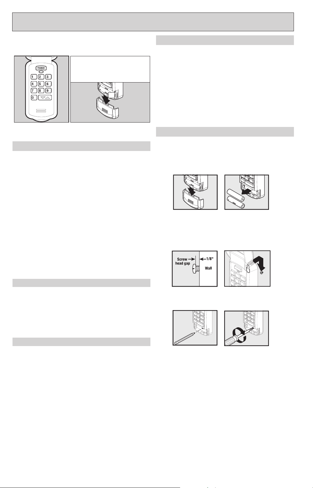
PROGRAM WIRELESS KEYPAD PROGRAM WIRELESS KEYPAD (abbreviated)(abbreviated)
Program Keypad before mounting.
Activate keypad by opening battery
compartment and pull protective
tab. Reinstall compartment door to
begin programming.
TAB
STEP 1) PROGRAMMING A PIN NUMBER (Single Door)
STEP 2) CHANGING DEFAULT PIN OF 3-5-7
Single Door Operation:
1. Ensure number pad back lighting is o.
2. Enter PIN number.
3. Press the UP/DOWN key.
4. Opener will operate.
STEP 3) OPERATING THE KEYPAD WITH THE OPENER
NOTE: Keypad will remain active for 15 seconds after
a successful entry is made. During this 15 seconds ANY
key will operate the opener.
QuickView Single Door setup.
Please see complete instructions that accompany keypad
Resetting a PIN:
Press and hold both the PROGRAM key and the Up/
Down key for about ve seconds.
The LED’s will slowly blink and then go out. When the
LED stops blinking, the old programming has been
successfully erased.
To create a new PIN, start with STEP 1.
Mounting Keypad
The keypad MUST be mounted within sight of the
garage door(s) at least ve feet above the oor and
clear of any moving door part.
1. Remove battery cover and batteries.
2. Drill 3/32” pilot hole for the top mounting screw
(included).
3. Install a screw into the pilot hole, leaving a 1/8”
gap between the screw head and wall.
4. Hook the slotted mount, on back of keypad, over
the screw.
5. Mark and drill a pilot hole for the bottom screw
(included) and secure keypad to wall (DO NOT
overtighten).
6. Reinstall batteries and cover.
1. Enter the factory default pin of 3-5-7.
2. Press PROGRAM key once.
3. Enter a new PIN of your choice (3-8 digits).
4. Press PROGRAM key once.
• Your PIN has been changed and your previous PIN
will no longer operate the keypad or opener.
The existing factory default Personal Identication
Number (PIN) for this keypad is the number sequence:
3-5-7
Sync the opener and the keypad by performing the
following:
1. Ensure the keypad back lighting is o.
2. Place garage door opener into remote control
PROGRAMMING MODE (SEE PAGE 10).
3. Press 3-5-7 in sequence on the keypad.
4. Press the UP/DOWN key 3 to 4 times slowly until
garage door opener operates.
• This completes the programming of a single door
opener (door 1) and keypad.
• IT IS RECOMMENDED THAT YOU CHANGE THIS PIN
FROM THE EXISTING FACTORY DEFAULT SETTING of
3-5-7. See STEP 2 below.
13
PROGRAM VEHICLE CONTROLS PROGRAM VEHICLE CONTROLS (abbreviated)(abbreviated)
Step 1) Clear HomeLink
Clear HomeLink by pressing and holding down the rst and
third buttons until the indicator on
the HomeLink blinks slow and then
fast for 20 seconds; then release
both buttons.
NOTE: Clearing the HomeLink
will remove all previously programmed garage door
openers.
Step 2) Train HomeLink to the Remote
Choose the button on the HomeLink that will be used to open
the door.
NOTE:
Hold the Remote two inches from the HomeLink
button.
Hold down the remote button.
While holding, press and hold
the chosen HomeLink button.
Hold down both buttons until the indicator on the HomeLink
blinks slow then fast. Once it blinks, release both buttons.
A. Press the chosen HomeLink button for two seconds and
release. Press that same button again for two seconds and
release. The long LED will ash blue and then turn o.
B. Press the HomeLink button a few more times until door
moves.
NOTE:
For additional instructions, see the motor
vehicle manual, or visit www.homelink.com or visit
www.geniecompany.com
NOTE:
Some vehicles require HomeLink to be purchased
and/or activated by the car dealership.
Programming HomeLink® System Programming Car2U
®
System
Step 1) Clear Car2U to default settings
The default setting for the Car2U system is:
• Button 1 = Genie® Manufactured Openers
• Button 2 = LiftMaster® Manufactured
Openers
• Button 3 = Wayne Dalton® Manufactured Openers
A. Press and hold buttons 1 and 3 for 20 seconds or until all
three LEDs begin to ash.
B. Release both buttons. The Car2U system is now set to the
Factory Default settings
NOTE:
Clearing the Car2U remote will remove all previously
programmed garage door openers.
Step 2) Program Car2U to the Opener
(Place opener into programming mode) - SEE PAGE 10
A. Press the designated Car2U button for two seconds and
release. Press that same button again for two seconds and
release. The long LED will ash blue and then turn o.
B. Press the Car2U button a few times more until door moves.
Step 3) Program HomeLink to the Opener
(Place opener into programming mode) - SEE PAGE 10
Step 3) Changing Factory Default Button for a Genie® Opener
A. Press and hold buttons 1 & 3 for ONE SECOND and
release—all three LEDs will light solid red.
B. Press and hold the button (2 or 3) to change it to—the
corresponding LED will ash. While continuing to hold
that button, press and release button 1. Press and release
button 1 again.
C. Release the button being held in step B and wait for the
LED to stop ashing. This button is now set. Repeat Step 2
for second Opener.
NOTE:
For additional instructions see the motor vehicle
manual, learcar2u.com.
14
SETTING UP ALADDIN CONNECT®SETTING UP ALADDIN CONNECT®
Perform these steps only after opener is fully installed, programmed and tested.
AVERTISSEMENT
POUR RÉDUIRE LE RISQUE DE BLESSURES GRAVES
VOIRE MORTELLES, LIRE ET COMPRENDRE TOUTES LES
INSTRUCTIONS.
1. NE JAMAIS laisser les enfants utiliser ou jouer avec les
commandes de l’ouvre-porte.
2. Placer l’étiquette d’AVERTISSEMENT en cas de coinçage
à proximité du bouton mural ou de la console murale de
manière à ce qu’elle soit bien en évidence.
3. NE JAMAIS PASSER SOUS LA PORTE EN MOUVEMENT.
4. NE JAMAIS PASSER SOUS UNE PORTE À L’ARRÊT
PARTIELLEMENT OUVERTE.
5. Le système d’exploitation Aladdin Connect ™ a été conçu
pour fonctionner sans surveillance. La porte peut se
déplacer de façon inattendue.
CONSERVER CES INSTRUCTIONS
CONSIGNES DE SÉCURITÉ
IMPORTANTES
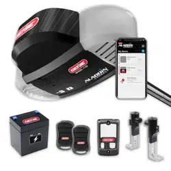
The Aladdin Connect® system is a convenient mobile device app to operate garage door openers/
controllers from anywhere.
The Aladdin Connect® app has the following features:
• Customize access for dierent users.
• Customize notications to receive alerts when the garage door is operated, by a specic user,
at a specic time or day.
• Review history of opener usage showing dates and times when the opener was operated and
by what user.
• Create custom rules to notify you or close the door at specic times or if your door is open for
a specic duration.
• Connect your opener to operate with smart home platforms.
WARNING
IMPORTANT SAFETY INSTRUCTIONS
TO REDUCE THE RISK OF SEVERE INJURY OR DEATH,
READ AND FOLLOW ALL INSTRUCTIONS.
1. Never allow children to operate or play with door
controls.
2. Install the entrapment WARNING placard next to the
wall control in a prominent location.
3. NO PERSONS SHOULD CROSS THE PATH OF A MOVING
DOOR.
4. NEVER GO UNDER A STOPPED/PARTIALLY OPEN DOOR.
5. The Aladdin Connect® operating system is designed
for unattended operation. The door could move
unexpectedly.
SAVE THESE INSTRUCTIONS
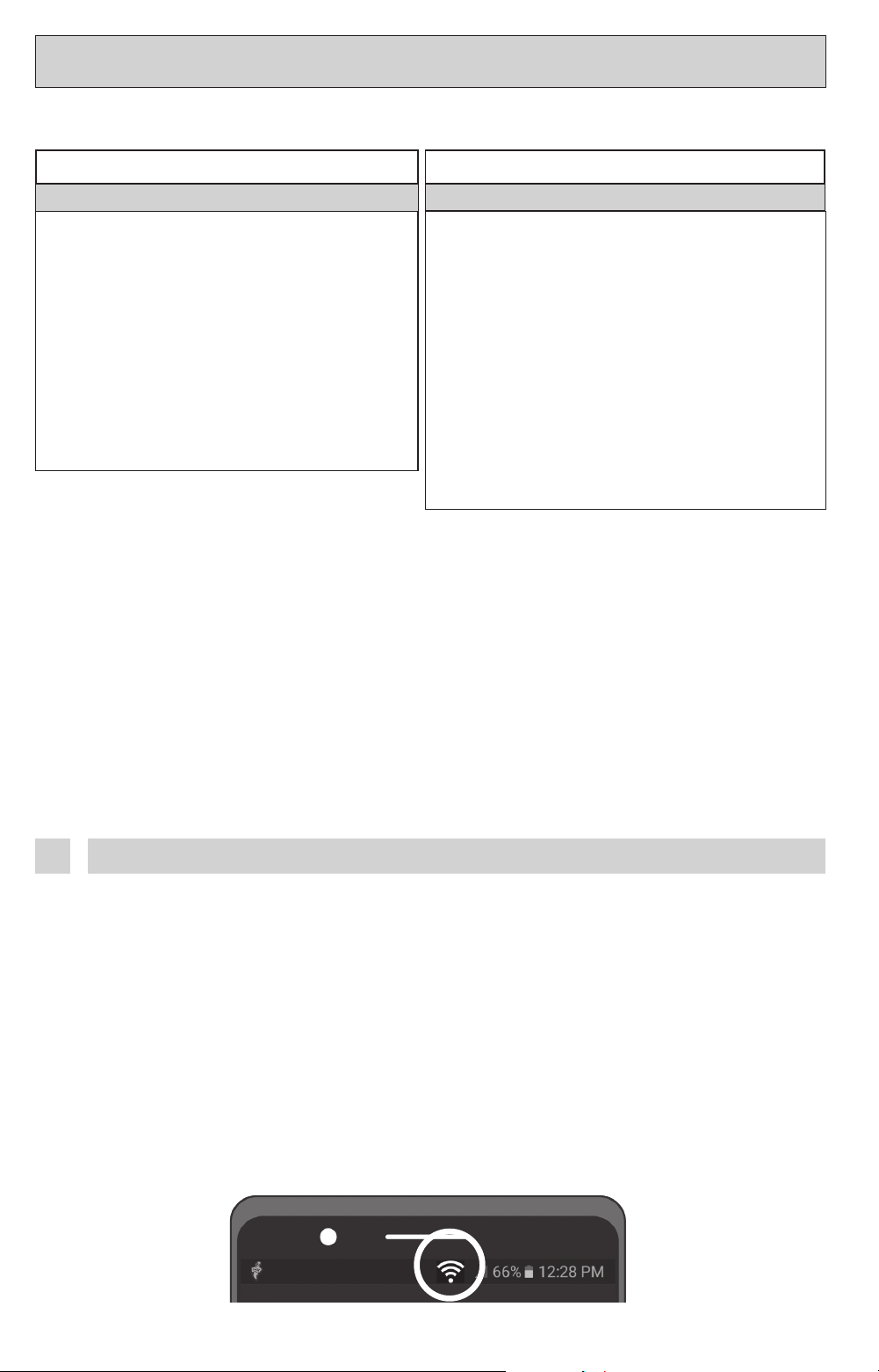
Before beginning the set-up process please verify the ability to receive a strong
Wi-Fi signal in the garage. Connect smartphone to the home Wi-Fi and walk into the
garage. Place phone where garage door opener will be mounted. The Wi-Fi signal
strength at that location must be at least two bars.
If home Wi-Fi signal does not adequately cover the garage, try the following steps to help
improve the signal strength.
• Make sure that the Wi-Fi router is out in the open, not behind a large electronics or in a
cabinet.
• Moving the Wi-Fi router closer to the garage.
• Purchase a Wi-Fi extender, available at most electronics stores.
Check Wi-Fi Signal 1
Genie® Integrated Aladdin Connect® Models
Device Wi-Fi Signal strength indicator
15
Scan for iOS app
Apple and the Apple logo are
trademarks of Apple Inc., registered in
the U.S. and other countries. App Store
is a service mark of Apple Inc.
Scan for Android app
Download the Aladdin Connect® app (Unless using 3rd party app)2
Follow steps per the app instructions.
• Create an account
• Add a device
• Set up Wi-Fi
• Add users and rules
For help at any time contact The Genie Company at 1-866-599-4995 or visit our website.
www.geniecompany.com/aladdinconnect
Scan the Aladdin Connect® QR Code on the front of
this manual or on the powerhead when prompted by
the Aladdin Connect® app.
Follow the Aladdin Connect® app instructions3
Install WARNING placard4
INSTALLER: LEAVE THIS MANUAL WITH HOMEOWNER
HOMEOWNER: SAVE THIS MANUAL FOR FUTURE REFERENCE
BELT/CHAIN DRIVE GARAGE DOOR OPENERS
PROGRAMMING, OPERATION, & MAINTENANCE MANUAL
SERIAL NUMBER DECAL
STOP
DO NOT return product to store,
visit www.geniecompany.com
or call Customer Service at: 1-800-35-GENIE
iDCM SERIAL NUMBER DECAL
To reduce the risk of injury to persons or damage to property, use this opener only with a sectional residential
door.
WARNING
Por reduire le risque de blessures ou de dommages materials, utillsez cet ouvre-porte uniquement pour une
porte a section re sidentielie.
AVERTISSEMENT
!
!
DO NOT use photocells from other manufacturers or openers with this opener.
lenses, or accessories.
NOTE: Use of this product, the software embedded within this product and the related application
software is subject to the Terms and Conditions available at:
www.geniecompany.com/aladdinconnect
Place the included unattended operation warning placard next to
the garage door opener’s wall button.
01/23
• Test door opener monthly:
Do not remove or paint over this label.
Mount wall control out of child’s reach (at least 5 feet above oor).
Place next to wall control.
• Do not let children walk or run under a closing door.
• Do not let children operate door operator controls.
• Always keep a closing door within sight.
There is a risk of a child becoming trapped under an
automatic garage door resulting in severe injury or death.
• In the event a person is trapped under the door, push
the control button or use the emergency release.
• This operator system may be equipped with an unattended
operation feature. The door could move unexpectedly.
Refer to your owner’s manual.
Place 1-1/2 inch object (or 2x4 laid at) on oor.
If door fails to reverse on contact, adjust opener.
If opener still fails to reverse door, repair or replace opener.
42103A
16
Force Settings:
Force settings are pre-programmed at the factory and applied during the Open/Closed Limit
settings steps. For normal use, these settings should not need adjustment.
Conditions possibly requiring adjustments are:
• Doors with very sti weather seals.
• Doors that start down, STOP, and reverse before closing.
• Doors that start up, but STOP before they completely open.
AVERTISSEMENT
!
Pour éviter les blessures ou des dommages
• NE JAMAIS régler la force pour compenser des
dommages, y compris une porte mal équilibrée, un
rail de porte coinçant, ou des ressorts cassés.
• Tous les mois, EFFECTUEZ LE TEST D’INVERSION AU
CONTACT.
WARNING
!
TO AVOID INJURY OR DAMAGE
• NEVER adjust the force settings to adjust for damage,
including an unbalanced door, binding door track, or
broken spring.
• Perform a CONTACT REVERSE TEST monthly.
1. Press and hold both UP & DOWN arrow buttons until the
ROUND LED turns RED. Release buttons.
• LEDs will show current force level. SEE CHART.
2. Press either the UP or DOWN arrow button until the
desired UP force setting is shown. SEE CHART.
3. Press the PRGM button to lock the desired UP FORCE
setting.
• LEDs will now show the current DOWN FORCE setting.
SEE CHART.
4. Press either the UP or DOWN arrow button until desired
DOWN force setting is shown. SEE CHART.
5. Press the PRGM button to lock the desired DOWN FORCE
setting.
• Both LEDs will turn BLUE then go out conrming that the
force settings have been changed and are locked.
6. Opener is now ready to operate and test.
7. Operate door from the wall console two full cycles then
perform safety contact reverse test.
Flashing RED
PRESS & RELEASE
See Chart for
Force level
indicators.
Press PRGM to
lock settings
FORCE SETTING CHART
Force Level Long LED Round LED
1 (LOWEST) OFF BLUE
2 BLUE OFF
3 BLUE BLUE
4 OFF VIOLET
5 VIOLET OFF
6 VIOLET VIOLET
7 OFF RED
8 RED OFF
9 (HIGHEST) RED RED
Force Adjustment Guide:
SPECIAL INSTALLATION INFORMATIONSPECIAL INSTALLATION INFORMATION
4
17
CLEARING MEMORY OF REMOTES & WIRELESS WALL CONSOLE
NOTE:
Clearing memory of remotes from the powerhead
will clear ALL programmed remotes, wireless keypads and
vehicle transmitters. The opener will no longer recognize
any signal from any remote device, including a missing
remote device. This does not include Aladdin Connect
®
.
All remaining (or recovered) remotes, vehicles and
wireless keypads MUST be reprogrammed.
NOTE:
The garage door opener will operate normally
using the wired wall console, if applicable.
1. Press and hold the SET/PRGM button until
the ROUND LED turns BLUE, then release.
The LONG LED will then ash PURPLE.
2. To clear all RF devices, except the Wireless
Wall Console, when used (transmitters/
keypads/HomeLink/Car2U):
• Press and hold both the UP & DOWN
buttons at the same time until both LEDs
turn BLUE.
• Release to erase RF devices.
3. And/or, to clear ONLY the Wireless Wall
Console:
• While in programming mode, press and
hold both the UP and DOWN buttons
at the same time until both LEDs turn
GREEN.
• Release to erase the Wireless Wall
Console.
4. Press any remote button. The operator
should NOT run.
1. Enter Programming Mode
Solid Blue Flashing Purple
Solid Blue
2. Press and Hold + & - Buttons
Release when
LEDs turn o
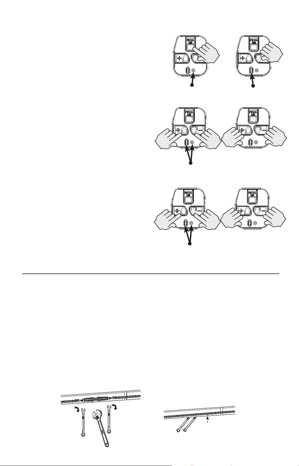
If excessive chain/belt sag is noticed below the rail:
1. Open the door until carriage is about mid travel and stop.
2. Disengage the carriage and manually close the door.
3. Loosen nuts on turnbuckle using 7/16” wrenches.
4. Rotate turnbuckle counter-clockwise until slack is removed from chain/belt.
5. When measured on the opposite side of the rail from the turnbuckle, a properly adjusted
chain/belt will have a 1/4” gap to the bottom of the rail.
6. Tighten nuts to secure turnbuckle.
7. Be sure that chain/belt is not twisted or bound.
8. Manually open door to re-engage carriage to turnbuckle.
1/4”
Chain/Belt Adjustments for Tube Type Rails:
NOTE: Might be necessary after unit is installed and run for the rst time.
Solid Green
3. Press and Hold + & - Buttons
Release when
LEDs turn o
18
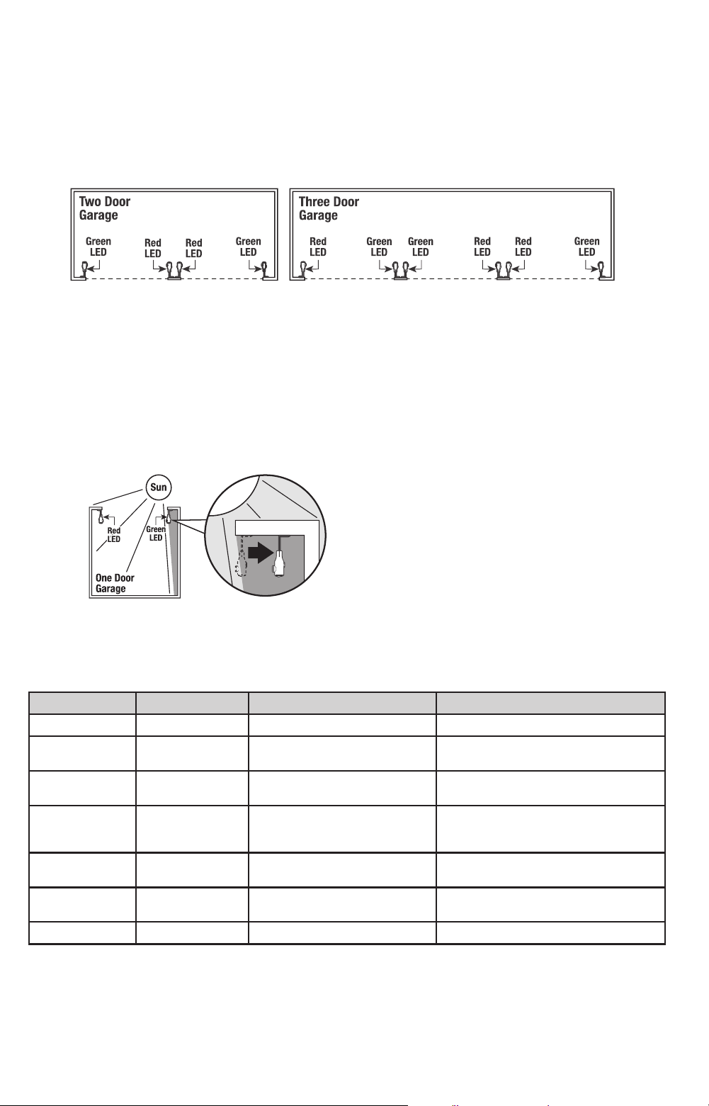
This view is looking down at the garage from above, with the dotted lines representing the
garage door opening.
• The Safe-T-Beam sensor with the RED LED is the transmitting device. The Safe-T-Beam sensor
with the GREEN LED is the receiving device.
• On doors that are right next to each other, always place the RED sensors facing in opposite
directions of each other. The pattern should look like the image below.
NOTE: Only use Safe-T-Beam sensors that are included with this opener. DO NOT use other brands or
types of safety sensors on this opener.
Location of Safe-T-Beam Pairs
RED LED Green LED Possible Problem Solution
ON ON Normal Operation None Required
OFF OFF
• Opener not powered
• Wiring from opener bad
• Check breakers, fuses, plugs
• Check wiring for shorts
OFF ON
• Wiring to source missing or bad
• Power has been interrupted
• Check wiring
• Remove power and reapply
2 BLINKS ON
• Beam not aligned
• Beam obstructed
• Sensor defective
• Check source, Sensor alignment
• Check for obstruction
• Contact Customer Support
2 BLINKS OFF
• Wire to sensor missing or bad
• Sensor defective
• Check wiring
• Contact Customer Support
3 BLINKS ON
• Sensor receiving interference • Determine source of interference
• Contact Customer Support
4 BLINKS ON
• Defective source beam (RED LED)
• Replace Safe-T-Beam set
Safe-T-Beam® Self-Diagnostic Troubleshooting Chart
When the garage door is up and something breaks the beams, the opener worklight turns on.
To turn STB Worklight function ON/OFF:
1. Unplug the power cord from the outlet and disconnect the Battery Backup, if Installed.
2. Press and hold the “DOWN” arrow (-) while plugging in the opener, then release.
3. Repeat to toggle ON/OFF.
Dealing with Sunlight Interference
This view is looking down at the garage from above.
• Direct sunlight can create interference with the GREEN Safe-T-Beam sensor and cause the
opener to detect an obstruction.
• Determine which side of the garage receives direct sunlight and position the RED sensor on
that side.
• Sensors can be positioned further away from the door opening if necessary to avoid sunlight,
but be sure to maintain alignment with the other sensor.
19
Installing Battery Backup
Single Bulb Models with External Battery Backups:
1. Unplug powerhead from power source.
2. Attach BBU assembly next to the opener and
install mounting screws to ceiling or framing.
3. Plug battery harness into plug located at the top
of the powerhead.
Dual Bulb or Integrated LED Models with External
Battery Backups:
1. Unplug powerhead from power source.
2. Tilt BBU approximately 45° and lower into slots in
the top rear of the powerhead.
3. Fasten to powerhead with 2 supplied self tapping
screws, and reconnect powerhead to power
source. Self tapping screws will self tap through
the cover (there are no holes in rear cover).
45
Testing The Genie Battery Backup
NOTE: It is recommended to charge the battery backup for 48 hours prior to testing.
Initially, the opener may not operate from the battery backup mode if battery is not
fully charged.
1. Turn o power to opener by unplugging from outlet or turning o breaker.
2. Press wall control or remote control.
NOTE: Opener will run at a reduced speed when operating from battery backup.
NOTE: See troubleshooting guide in this manual if any of the steps above fail.
Work light will not operate while in battery backup mode. (Courtesy white LED’s will illuminate.)
3. After successful test, reconnect powerhead to power source.
See the troubleshooting section for condition LED’s that will illuminate once
the Battery Backup is operational.
Both LEDs will signal solid GREEN under normal, fully charged, conditions.
Battery backup devices from other manufacturers will not operate with this opener.
Use only the Genie (OEM) product provided and other OEM replacement products.
Perform these steps only after the opener is fully installed, programmed, and tested.
Dual Bulb or
Integrated LED Models
Single Bulb
Models
CAUTION
TO PREVENT POSSIBLE SERIOUS INJURY or DEATH from
electrocution AND REDUCE RISK of FIRE
-Disconnect ALL electric power sources and battery power BEFORE
performing ANY service or maintenance.
Install only in DRY locations - NOT INTENDED FOR OUTDOOR USE.
Use only 12V, 5AH, SLA replacement battery. (P/N 111658.0002.S).
!
POUR ÉVITER LES BLESSURES GRAVES OU LA MORT par
électrocution ET RÉDUIRE LE RISQUE D’INCENDIE
-Débrancher toutes les sources d’alimentation électrique et la pile
AVANT d’eectuer des opérations de réparation ou d’entretien.
Installer uniquement dans des endroits SECS - NE DOIT PAS ÊTRE
UTILISÉ À L’EXTÉRIEUR.
Utiliser uniquement une pile de remplacement de 12V, 5AH, SLA.
(P/N 111658.0002.S).
ATTENTION
!
20
Pour réduire le risque de blessures graves
voire mortelles, lire et comprendre toutes les
instructions.
1. NE JAMAIS permettre aux enfants d’actionner ou de jouer avec les commandes de la porte.
2. Tenir les télécommandes hors de la portée des enfants.
3. TOUJOURS garder en vue la porte en mouvement et tenir à l’écart toute personne ou objet jusqu’à ce que la porte
soit totalement fermée. PERSONNE NE DOIT TRAVERSER LA TRAJECTOIRE D’UNE PORTE EN MOUVEMENT.
4. NE JAMAIS PASSER SOUS UNE PORTE À L’ARRÊT PARTIELLEMENT OUVERTE.
5. Tester l’ouvre-porte une fois par mois. La porte de garage DOIT inverser sa course au contact d’un objet de 4 cm
(planche de 5 sur 10 cm) posé à plat sur le sol au centre de l’ouverture de la porte. Après avoir réglé la force ou
la limite de la course, retenter l’ouvre-porte de garage. Un mauvais réglage de l’ouvre-porte peut entraîner des
blessures graves voire mortelles
6. Utiliser, dans la mesure du possible le déclenchement d’urgence uniquement lorsque la porte est fermée. Utiliser le
déclenchement d’urgence avec prudence lorsque la porte est ouverte. Des ressorts faibles ou brisés peuvent faire
descendre la porte rapidement ce qui peut entraîner des blessures graves voire mortelles.
7. VEILLER À CE QUE LA PORTE SOIT CORRECTEMENT ÉQUILIBRÉE. Consulter le manuel du propriétaire de la porte
de garage. Une porte déséquilibrée pourrait entraîner de graves blessures voire mortelles. Demander à un
technicien spécialisé en système de portes de se charger des réparations des câbles, des ressorts et de toute autre
quincaillerie.
CONSERVER CES INSTRUCTIONS
IMPORTANTES CONSIGNES DE SÉCURITÉ
AVERTISSEMENT
!
To reduce the risk of severe injury or death, read
and follow all instructions.
1. NEVER let children operate or play with the door controls.
2. Keep remote away from children.
3. ALWAYS keep the moving door in sight and away from people and objects until door is completely closed. NO ONE
SHOULD CROSS THE PATH OF THE MOVING DOOR.
4. NEVER GO UNDER A STOPPED, PARTIALLY OPEN DOOR.
5. Test opener monthly. The door MUST reverse on contact with a 1-1/2” high object (or 2” x 4” board laid at) at the
center of the doorway on the oor. After adjusting either the force or limit of travel, retest door opener. Failure to
adjust the opener properly may cause severe injury or death.
6. When possible, use emergency release only when door is closed. Use caution when using this release with the door
open. Weak or broken springs are capable of increasing the rate of door closing and increasing the risk of severe
injury or death.
7. KEEP DOORS PROPERLY BALANCED. See your garage door Owner’s Manual. An improperly balanced door increases
the risk of severe injury or death. Have a trained door system technician make repairs to cables, spring assemblies,
and other hardware.
SAVE THESE INSTRUCTIONS
IMPORTANT SAFETY INSTRUCTIONS
WARNING
!
WARNING
!
Use of any other wall control can cause unexpected operation of the door
and loss of lighting feature. Locate wall console within sight of the door but
far enough from door to prevent contacting it while operating the console.
Control must be at least 5 feet above the oor to prevent small children
from operating it.
MAINTENANCEMAINTENANCE
5
A
VERTISSEMENT
!
L’utilisation d’une autre commande murale pourrait produire des résultats inattendus de la
porte ainsi que le dysfonctionnement de l’éclairage. Localisez la console murale en vue de
la porte et susamment loin de la porte pour éviter tout contact pendant l’utilisation de
la console. La commande doit être à une hauteur minimale de 1,5 m au-dessus du sol an
que les jeunes enfants ne puissent pas l’atteindre.
21
Regular Maintenance Schedule
Regular inspection/maintenance for the door and opener should be performed at
regular intervals to ensure the system runs at peak safety, performance, and eciency.
MAINTENANCE ITEM INTERVALS DETAILS
Contact Reverse Test Monthly See Page 9 to run system test.
Lubricate Door
Hardware
Monthly Lubricate Rollers & Hinges with a light weight general
purpose grease.
Safe-T-Beam® system
check
Monthly Check wiring for loose connections, cracks or worn
insulation.
Clean lenses of dirt & debris.
Door Balance Monthly See Maintenance Detail below
Battery Backup System Monthly Unplug opener from outlet. Test opener with remote or
wall console. Replace battery if needed. See page 19.
Chain/Belt
Adjustments
Yearly Inspect chain/belt for excessive slack, adjust as
necessary.
Remote Battery
Replacement
As Needed See Maintenance Detail next page
Light Bulb
Replacement
As Needed See Maintenance Detail next page
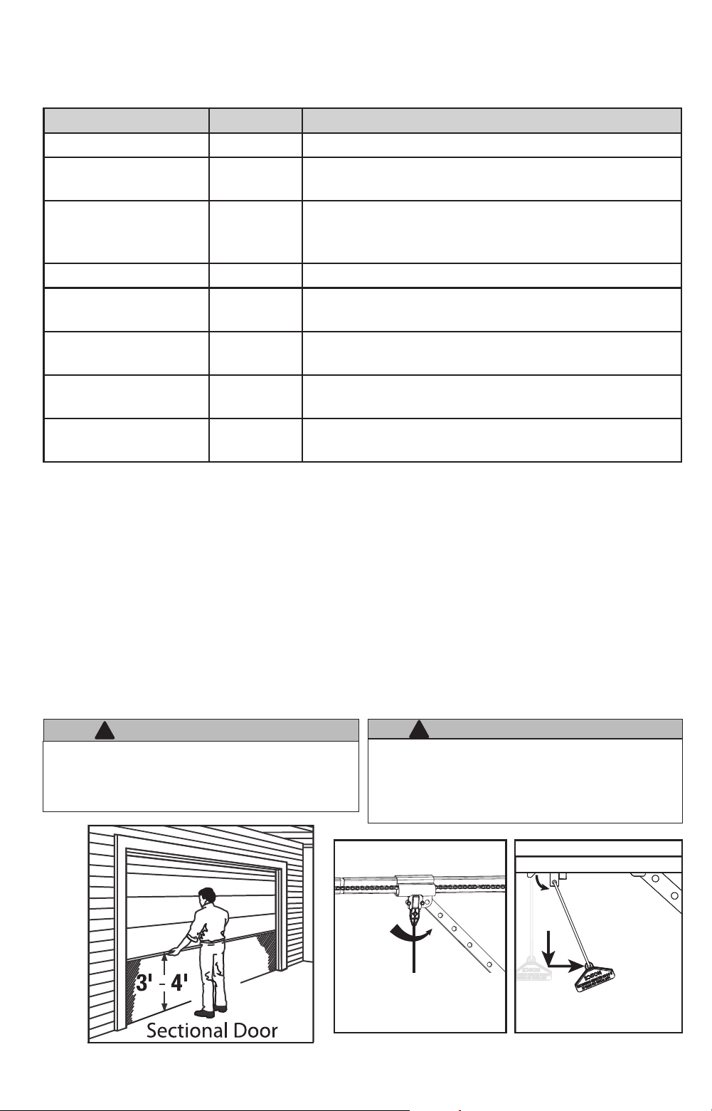
Perform the Door inspection as follows:
With the door closed, pull manual emergency release handle DOWN and away from door and let go to
disengage the carriage from the drive chain or belt FIG.1.
• Raise and lower the door manually. Door should move freely and smoothly.
• Raise door manually about 3’ to 4’ feet from oor and let go.. Door should remain stationary or slowly
drift closed. FIG. 1.
If door opens or closes rapidly, CONTACT A TRAINED DOOR SYSTEM TECHNICIAN to have your door
springs serviced.
• Close the door.
Carriage Adjustment (Release/Engagement)
• Place the carriage in the “engage” position reverse of FIG. 2.
• Operate door using remote or wall control. The carriage will reattach itself to the drive chain/belt.
Door Inspection and Maintenance
FIG.1 FIG 2
WARNING
!
• Garage door hardware (springs, cables, brackets, pulleys, etc.) are under
extreme pressure and tension.
• DO NOT attempt to repair or adjust door springs or any hardware, and
DO NOT OPERATE garage door automatically or manually if door is
improperly balanced or springs are broken.
• CONTACT A TRAINED DOOR SYSTEM TECHNICIAN.
AVERTISSEMENT
• La quincaillerie de la porte de garage (ressorts, câbles, supports,
poulies, etc.) sont sous des pressions et des tensions extrêmes.
• NE PAS réparer ni régler les ressorts de la porte ou toute autre pièce
de quincaillerie et NE PAS ACTIONNER la porte manuellement ou
automatiquement si elle n’est pas correctement équilibrée ou si des
ressorts sont cassés.
• CONTACTEZ UN TECHNICIEN SPÉCIALISÉ EN SYSTÈME DE PORTES
DO NOT use release cord to pull door.
Chain/Belt Drive CHANNEL
Disengage the carriage by pulling
the release handle down, toward
the door and then releasing
Chain/Belt Drive TUBE RAIL
Disengage the carriage by pulling
the release handle down, then
releasing
!
22
Remote Battery Replacement
Use a screwdriver and/or a small coin to remove screws and open case as shown. Remove and
replace CR2032 coin cell battery.
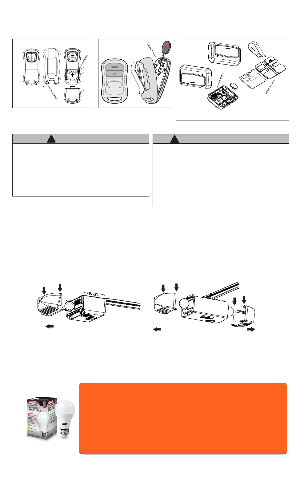
1. Disconnect power to opener.
2. Open powerhead lens covers by pressing down on upper locking tabs and pull away from powerhead.
3. Replace old light bulbs with 60 Watt MAXIMUM incandescent, CFL or LED equivalent**.
* Genie LED light bulbs, which are specically made for garage door openers, are recommended.
4. Install lens cover(s).
5. Reconnect power to door opener.
6. Test light operation.
NOTE: Use of standard LED bulbs may reduce the range of your remote controls*.
WARNING
!
• Use extreme caution when working from a ladder or step
stool or serious injury can occur.
• When replacing light cover, make sure wires are not
pinched or near moving parts.
• Use only properly rated incandescent, LED or CFL light
bulbs.
• DO NOT use bulbs with a rating greater than 60 Watts.
• Use A19 size light bulbs. DO NOT use bulbs having a short
neck.
AVERTISSEMENT
!
• Faire particulièrement attention lors de travaux eectués
depuis une échelle ou en escabeau.
• En referment le couvercle de l’éclairage, s’assurer que les
ls ne sont ni coincés ni près des pièces mobiles.
• Utilisez uniquement incandescence correctement classé,
LED ou des ampoules uocompactes.
• NE PAS utiliser des ampoules avec une note supérieure à
60 Watts
• Utilisez A19 ampoules de taille. NE PAS utiliser des
ampoules ayant un cou court.
* Genie LED light bulbs are designed to reduce or eliminate
reduced remote range issues caused by common LED
bulbs. They also oer better product life by making them
resistant to vibration caused by the opener, and cold or
damp weather. See website for details at
www.geniecompany.com.
**Integrated Aladdin Connect® models require a MINIMUM 40 Watt or equivalent
bulb, 60 watt maximum.
Models equipped with integrated LED lighting require specialty kits available for
order in the replacement parts section.
Lightbulb Replacement
Push down tabs
Pull light covers away from powerhead
Push down tabs
Pull light cover away from powerhead
1 Light Models 2 Light Models
BATTERY
BATTERY
COVER
REMOTE
BUTTON
REMOVE
SCREW
FRONT OF
REMOTE
FRONT OF
REMOTE
BACK OF
REMOTE
REMOVE
SCREWS
NOTE: Battery “+” sign orientation
Battery “+” sign faces towards buttons
Remove screws
Remove screw
Remove
screws
23
Visit www.genicompany.com or call Customer Service at 1-800-35-GENIE.
Need help or have questions? DO NOT RETURN to the store.
PROBLEM: WHAT TO DO:
Opener does NOT
operate when wall
control is pressed.
• Turn Sure-Lock™ OFF See page 5.
• Check power source.
– Plug a lamp into outlet used for powerhead. If lamp works, power source is OK.
– If not, check fuse or circuit breaker.
• If power is OK,
– Check connections at powerhead terminals and at wall console.
• Check for reversed, broken or cut wires. Staples can cut insulation and short wires. Repair or replace.
Opener runs, but
door does not
move.
• Make sure carriage is engaged with chain/belt turnbuckle. Refer to installation
poster or download poster from www.geniecompany.com
• Check to make sure chain/belt is not broken or o its pulley.
Opener works from
wall control, but
NOT from remote.
• Check all remotes.
• Replace remote battery. See page 22.
• Program remotes to powerhead. See page 10.
Remote has less
than 25 feet
operating range or
no operation.
• Relocate remote inside car and /or point remote at garage door.
• Replace battery. See page 22.
• Reposition door opener antenna.
• Eliminate possible competing signals (radio, etc.).
• LED bulbs may be interfering with remote signal. See page 22.
Door starts down,
then STOPS and
goes back up.
OR
Safe-T-Beam
®
System malfunction.
• If a NEW installation, check Door Arm position. Refer to Installation poster or download poster
from www.geniecompany.com.
• If NEW Installation, make sure ONLY the Safe-T-Beams® that came with this opener are installed.
• Check if limits are properly set. See pages 7-8. Adjust limits as needed.
• Check if Safe-T- Beam® red LED is ashing. See page 18, Safe-T-Beam® system check.
• Check Safe-T-Beam® system for beam obstruction or misalignment of lenses. See page 18, Safe-T-Beam®
system.
• Check garage door for binding. See page 21.
• If an operational problem exists, and opener will not close, the opener can be forced to close as follows:
Press and hold the wall control button until door is completely closed.
• Check for interference from adjacent Safe-T-Beam® units. See page 18.
• Contact Genie at 1-800-35-GENIE.
Door starts down,
then STOPS before
it is closed.
OR Door will only
open.
• Check Safe-T- Beam®wire connection at powerhead and at STBs. See page 18, Safe-T-Beam® system
check.
• Check if limits are properly set. See pages 7-8. Adjust limits as needed.
• Check CONTACT REVERSE. See page 9.
• Check garage door for binding. See maintenance and adjustment. Page 21.
• Check closing “FORCE” control. See page 9, or Force settings. Page 16.
Door starts up, but
STOPS before it is
completely open.
• Check if limits are properly set. See pages 7-8. Adjust limits as needed.
• Be sure door, opener, springs are in good repair, properly lubricated and balanced.
• Check closing/opening “FORCE” control. See page 9, or Force settings Page 16.
• If you suspect a problem with the garage door hardware or springs, visit www.geniecompany.com
and use the “dealer locater” to hire a local door service professional.
NEVER try to repair door hardware or springs yourself.
Door will only run
closed.
• Turn Sure-Lock™ OFF See page 5.
• Check if limits are properly set. See pages 7-8.
• Check door balance, condition, and door spring. See page 21.
• Check opening “FORCE” control. See page 9, or Force settings. Page 16.
• If you suspect a problem with the garage door hardware or springs, visit www.geniecompany.com
and use the “dealer locater” to hire a local door service professional.
NEVER try to repair door hardware or springs yourself.
Door opener starts
for no reason.
• Button stuck on wall control or remote.
• Was remote lost or stolen? Erase all remotes from powerhead memory and program new remotes. See page
17.
Noisy operation.
• Be sure all door fasteners are tight.
• Be sure garage door is in good repair, properly lubricated and balanced.
• Be sure opener is in good repair.
Door opener runs
slow.
• Check operating condition of door. Door may need professional repair/adjustment.
• Is this opener installed on a one-piece door? This opener is not designed to operate a one-piece door.
Use the guide below along with the self diagnostic powerhead LEDs to help
troubleshoot any problems.
TROUBLESHOOTINGTROUBLESHOOTING
6
24
POWERHEAD LED SIGNALS
Powerhead LED
Possible Problem
Solution
Round LED Long LED
OFF OFF
Normal operation. None required.
No response from unit.
Check power supply.
Contact a trained door system professional.
ON/RED/
STEADY
ON/RED/
STEADY
Limits NOT set properly. Re-program limits, see pages 7-8.
ON/RED/
FLASHING
ON/RED/
FLASHING
Program error. Unplug unit, wait 5 seconds, plug in.
Component failure. Contact a trained door system technician.
ON/BLUE/
FLASHING
OFF Remote NOT programmed. Program remote, see page 10.
ON/PURPLE/
FLASHING
OFF Remote NOT programmed. Program remote, see page 10.
ON/RED/
FLASHING
OFF
Safe-T-Beam® physical obstruction. Remote obstruction, recheck unit.
Safe-T-Beam® signal interference.
Check alignment of Safe-T-Beam® pair and
nearest other Safe-T-Beam® pair, see page
18.
OFF
ON/RED/
FLASHING
Door contact in UP or DOWN travel. Remove obstruction.
Door component failure detected.
Check door spring, track, rollers, hinges and
xtures.
OFF
ON/RED/
STEADY
Thermal cutout.
DO NOT unplug unit.
Wait until LED clears before operating.
ON/PURPLE/
STEADY
ON/PURPLE/
STEADY
Component error. Contact a trained door system technician.
OFF
ON/BLUE/
FLASHING
Door will not open.
Check Sure-Lock™. Sure-Lock™ should be
OFF for
normal operation (see page 5).
ON/PURPLE/
FLASHING
ON/PURPLE/
FLASHING
Radio receiver error.
Unplug the unit. Wait 5 seconds and plug
the unit
back in. If problems persist, contact a
trained door
system technician.
Battery Backup Troubleshooting LED Signals
ON/GREEN
STEADY
ON/GREEN
STEADY
OK=Charged, Battery Backup
None Required
ON/GREEN
FLASHING
ON/GREEN
FLASHING
Discharging, Battery Backup
Power is out. Battery in use.
ON/YELLOW
FLASHING
ON/YELLOW
FLASHING
Charging, Battery Backup
None Required
ON/RED TO YELLOW
FLASHING
ON/RED TO YELLOW
FLASHING
Dead Battery, Battery Backup
Allow to charge 48 hours. If charging
fails, Replace Battery.
ON/WHITE STEADY ON/WHITE STEADY Battery Backup in Operation
No Fault. Courtesy light while in battery
backup mode. Light will turn o after 4
minutes.
LED DISPLAY UNDER NORMAL OPERATING CONDITIONS
NO LED DISPLAY BOTH LEDs = STEADY GREEN
Standard Models
Battery Back-up Models
25
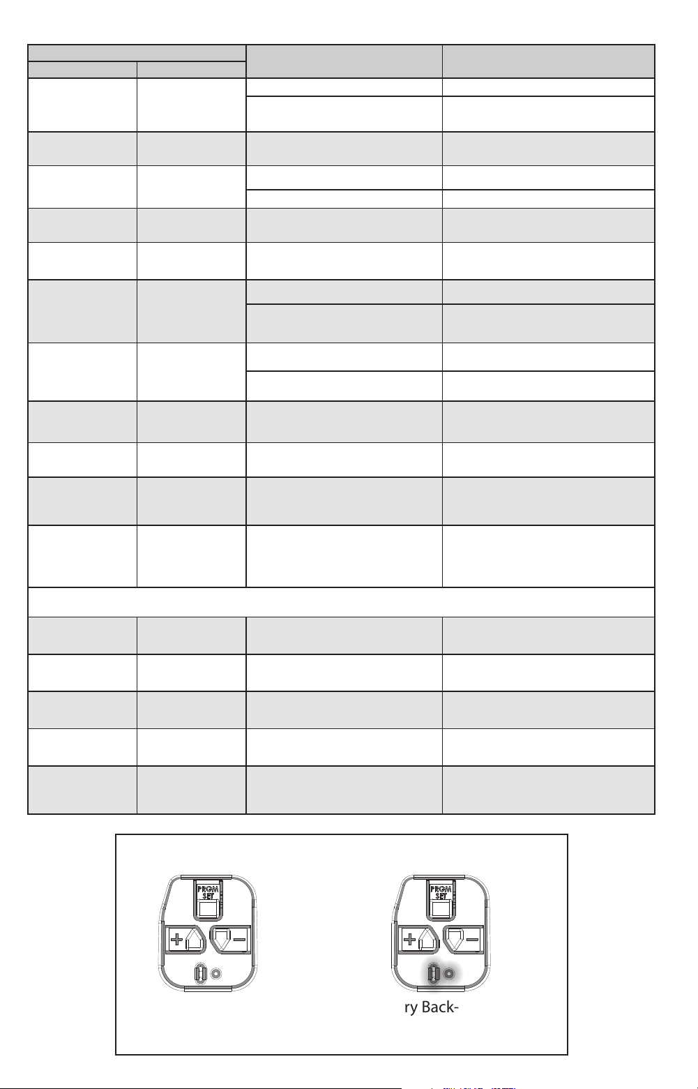
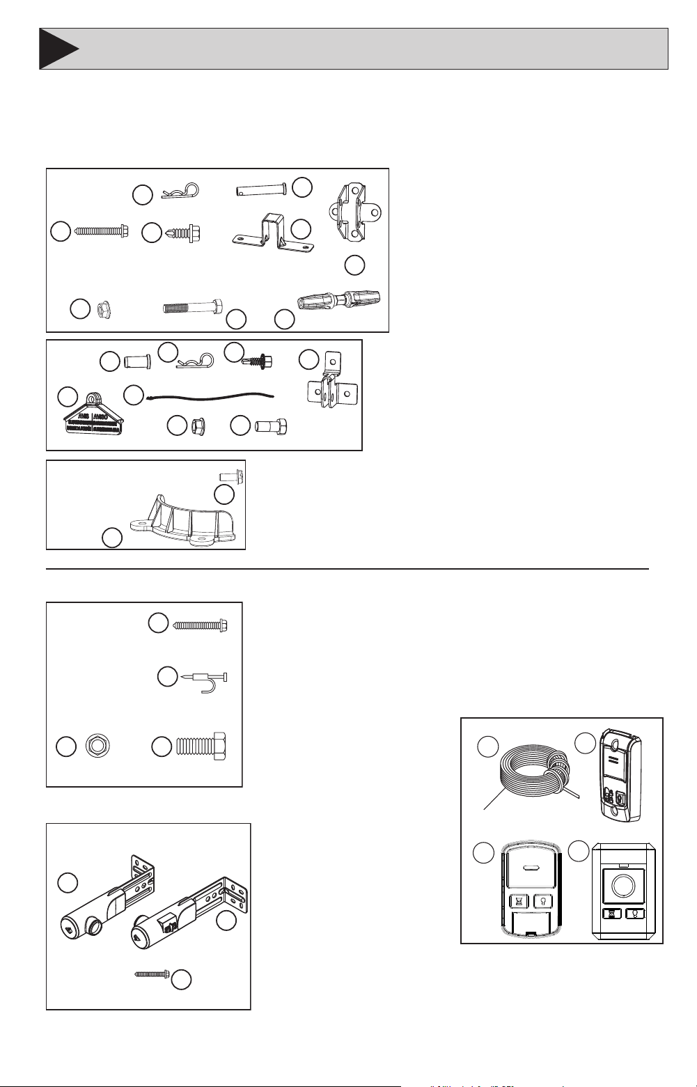
REPLACEMENT ASSEMBLY PARTSREPLACEMENT ASSEMBLY PARTS
7
C 37105S.S PARTS PK, INSTALL, GREEN
Item # Part Number Description ...... Qty.
1 BOLT,HH,PLD,5/16-18 X 3 ..................2
2 NUT,5/16-18 HX SERR FLG .................2
3 SCR,LAG,HWH,TPG,5/16”X1 ..............2
4 PARTS PK,INSULATED STAP ................30
Please have your specic opener model number (on opener powerhead) or serial
number (front of this manual) when ordering parts.
TUBE RAIL PARTS ONLY
ALL RETAIL OPENERS
E 37220R Safe-T-Beam Set
Item # Part Number Description ........ Qty.
1 XMTR ASSY,STB 1 ............................1
2 RCVR ASSY,STB 1 ............................1
3 SCR,#10-16 X 1.25 ..........................4
D 39012R.S PARTS PACK, CLEAR,
FOR BELT MODELS ONLY
Item # Part Number Description Qty.
1 COVER,BELT RETAINER ...........................................1
2 SCR,SF TP #6-18 X 3/8 ...........................................2
B 39011R.S PARTS PK,MOUNTING,BLUE
Item # Part Number Description Qty.
1 PIN, CLEVIS .....................................................2
2 PIN, COTTER .....................................................2
3 SCREW, SELF TAPPING 1/4 -14 X 5/8 ......................3
4 BRACKET, HEADER .................................................1
5 EMERGENCY RELEASE HANDLE ..............................1
6 EMERGENCY RELEASE CORD ...................................2
7 NUT, FLANGE 3/8-16 .............................................. 2
8 BOLT, 3/6-16 X .87 .................................................2
A 39010R.S PARTS PK,MOUNTING,ORANGE
Item # Part Number Description Qty.
1 TURNBUCKLE 1
2 PIN,CLEVIS,5/16 X 1-3/4 ........................................ 2
3 COTTER,HAIRPIN,.0725 DI ...................................... 2
4 BOLT,HH,PLD,5/16-18 X 2 ......................................1
5 NUT,5/16-18 HX SERR FLG .....................................1
6 STRAP,RAIL,RECT ...................................................1
7 SCR,SERR HWH,AB,1/4-14 .....................................4
8 BRKT,HEADER,RECT RAIL .......................................1
9 SCR,LAG,HWH,TPG,5/16”X1 ..................................2
ACCESSORIES
Item # Part Number Description
1 35265B.S 90ft. LOW VOLTAGE WIRE SPOOL
2 39165R WIRED WALL CONSOLE
3 41006R WIRELESS WALL CONSOLE (RETAIL)
4 39902R WIRELESS WALL CONSOLE (PRO)
14
5
2
3
6
7
9
8
ORANGE BAG
5/16" x 1-3/4"
Lag screw (x2)
1/4"- 20 - 3/4"
Self-drilling screw (x4)
Header bracket
Rail Strap
Turnbuckle
Bolt 5/16-18 x 2Nut 5/16-18 Serr.
Cotter Pin (x2)
Clevis Pin 5/16 x 1.75 (x2)
1
2 3
4
5
6
7 8
BLUE BAG
Cotter Pin (x2)Clevis Pin (x2) Screw Self Tap (x3)
Door Bracket
Bolt 3/8-.87 (x2)Nut 3/8-16 Hex (x2)Emergency Release Handle
Red Release Cord
1
CLEAR BAG
#6-18 x 3/8”
Self-Tap Screw (x2)
Cover, Belt Retainer
2
12
3
4
GREEN BAG
#8 - 3/4"
Self-tapping
screw (x2)
1/4"x 3/4"
Insulated staple (x30)
5/16" x 1-3/4"
Lag screw (x2)
5/16"- 18 - 3/4"
Bolt (x2)
5/16"-18 Lock nut ,
serrated (x2)
1
3
2
Safe-T-Beam® Set
Safe- T- Beam
®
sensor
Safe- T- Beam
®
source
1/4" x 1-1/4"
Lag screw (x4)
1
2
3
4
For Belt Models
Only
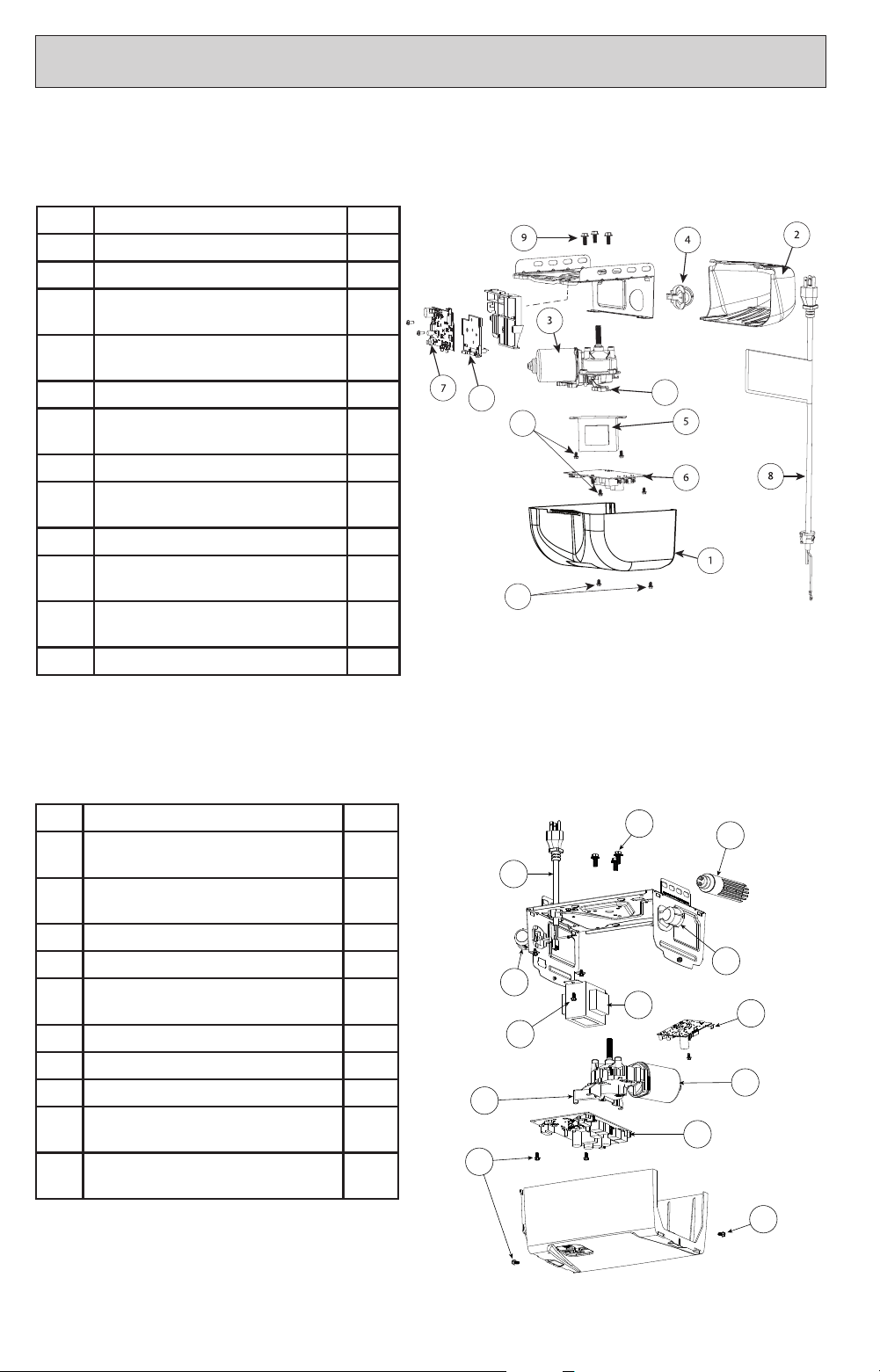
26
12
11
10
10
Single Bulb Powerhead Models
Item Description QTY.
1 Powerhead cover 1
2 Lens cover 1
3 Motor assembly (includes encoder
& wire)
1
4 Light socket assembly (regular bulb
only)
1
5 Transformer,120V 1
6 Circuit board assembly, main
(identify green or blue color)
1
7 Circuit board assembly, Wi-Fi 1
8 Power cord assembly (identify 4’
or 6’)
1
9 Screws, motor (3pk; M6-1x12) 1
10 Screws, cover and/or transformer
(3pk; #8x5/16)
1
11 Optical encoder replacement
assembly
1
12 Bracket, Wi-Fi board 1
Please have your specic opener model number (on opener powerhead) or serial
number (front of this manual) when ordering parts.
Common Parts - Dual Bulb Powerhead & Integrated LED Models
Item Description QTY.
1 Motor assembly (includes encoder
and wire)
1
2 Light socket assembly (identify bulb
type)
2
3 Genie LED bulb 2
4 Transformer, 120V 1
5 Circuit board assembly, main (identify
green or blue color)
1
6 Circuit board assembly, Wi-Fi 1
7 Power cord assembly (identify 4' or 6') 1
8 Screws, motor (3pk; M6-1x12) 1
9 Screws, cover and/or transformer
(3pk; #8x5/16)
2
10 Optical encoder replacement
assembly
1
1
4
5
6
7
2
10
3
2
9
9
9
8
REPLACEMENT POWERHEAD PARTSREPLACEMENT POWERHEAD PARTS
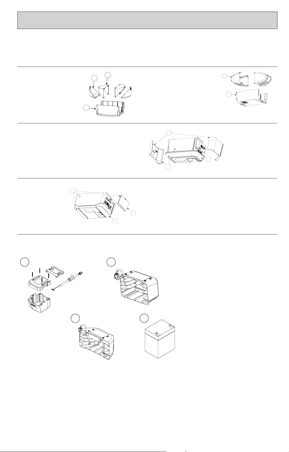
27
REPLACEMENT POWERHEAD PARTSREPLACEMENT POWERHEAD PARTS
Model Specic Parts
1-Piece Cover & Lens
1. Lens
2. Main Cover
1
2
2-Piece Cover & Lens
1. Lens
2. Secondary Cover
3. Main Cover
1
2
3
End Panel Design (Horseshoe LED)
1. Lens Kit
2. End panel kit (left & right sides)
3. Complete kit: Full cover, end panels,
lens, & LEDs
2
1
3
1
2
3
4
1
2
3
Hidden Panel Design (LED Ends)
1. Lens (1 end)
2. Hidden panel door
3. Complete kit: Full cover, hidden
panel door, 2 lenses, & LEDs
1. Battery case and hardware for
single bulb models
2. Battery case and hardware for
dual bulb models
3. Battery case and hardware for
integrated LED models
4. Battery only, all models
Battery Backup Cases & Battery Only
2
1
3
1
2
3
4
1
2
3
1 3
2 4
Please have your specic opener model number (on opener powerhead) or serial
number (front of this manual) when ordering parts.
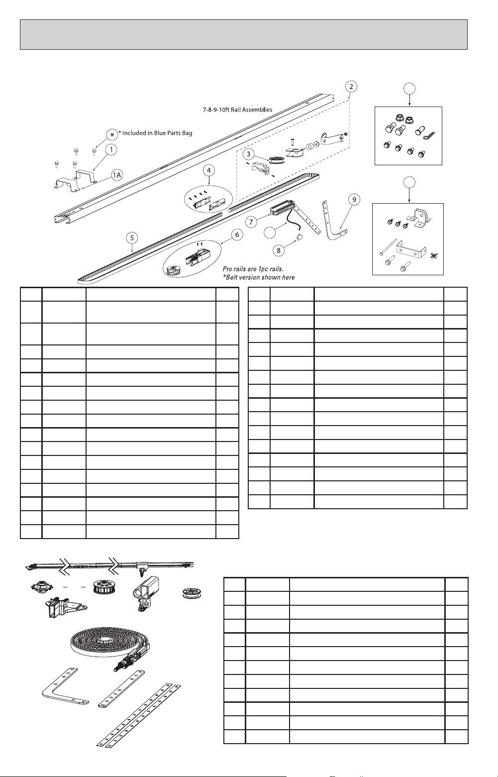
28
Item Part Number Description QT Y.
1 36728A.S Head To Rail Bracket (Need 2 for Chain, 1
for Belt)
1
1A 36987A.S Head To Rail Bracket Belt Guard (for Belt
only)
1
2 37857R.S Tensioner Assembly 1
3 36764A.S Pulley Tensioner 1
4 37557R.S Chain Bullet Assembly 1
37556R.S Belt Bullet Assembly 1
5 37562R.S Chain & Bullet Assembly, 7 ft 1
37562S.S Chain & Bullet Assembly, 8 ft 1
37562T.S Chain & Bullet Assembly, 10 ft (292") 1
39381R.S Chain & Bullet Assembly, 10 ft (303") 1
37561R.S Belt & Bullet Assembly, 7 ft 1
37561S.S Belt & Bullet Assembly, 8 ft 1
37561W.S Belt & Bullet Assembly, 9 ft (268") 1
39380U.S Belt & Bullet Assembly, 9 ft (279") 1
37561T.S Belt & Bullet Assembly, 10 ft (292") 1
39380R.S Belt & Bullet Assembly, 10 ft (303") 1
10
11
12
Item Part Number Description QT Y.
6 37559R.S Chain Drive Sprocket Assembly 1
37558R.S Belt Drive Sprocket Assembly 1
7 36773R.S Carriage Assembly, 7 ft Doors 1
36773S.S Carriage Assembly, 8 ft Doors 1
36773T.S Carriage Assembly, 9, 10 ft Doors 1
8 37107C.S Carriage Release Handle 1
9 26013D.S Curved Door Arm 1
10 37461R.S Release Cord Assembly,7’ (32”) 1
37461S.S Release Cord Assembly, 8’ (44”) 1
37461T.S Release Cord Assembly, 9-14’ (116”) 1
11 37049R.S Installation Parts Pack (Blue Bag) 1
12 37047R.S Mounting Parts Pack (Orange Bag) 1
NS 37714S.S Wire Clips, (50 pcs) 1
NS 38245R.S 3PC Service Rail, C-Channel Chain Drive Rail 1
NS 38246R.S 3PC Service Rail, C-Channel Belt Drive Rail 1
CHANNEL & TUBE RAIL PARTSCHANNEL & TUBE RAIL PARTS
Please have your specic opener model number (on opener powerhead) or serial number
(front of this manual) when ordering parts.
Item Part Number Description QT Y.
A 39410R.S 5-pcs. Rail Assembly Complete (Chain) 1
39400R.S 5-pcs. Rail Assembly Complete (Belt) 1
B 39277R.S Sprocket Support Assembly (Chain) 1
39278R.S Sprocket Support Assembly (Belt) 1
C 38893R.S Carriage Assembly 1
D 39276R.S Idler Pulley 1
E 39352R.S Chain Assembly (7Ft) 1
39354R.S Belt Assembly(7Ft) 1
F 37476A.S Door Arm, Curved 1
G 37475A.S Door Arm, Straight 1
H 21243B.S Strap, Hanging, 3/4 X 25 2
or
A
B
C
D
E
F
G
H
Tube Rail Parts
Channel Parts
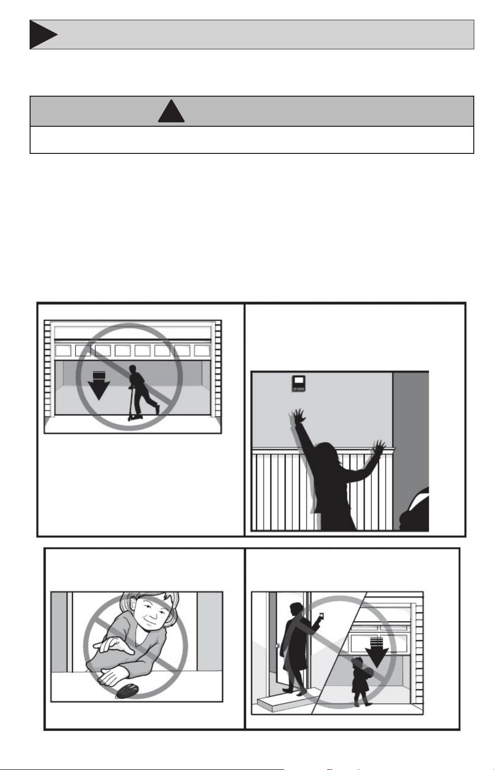
29
DASMA SAFETY GUIDELINESDASMA SAFETY GUIDELINES
8
Automatic Garage Door Opener Safety & Maintenance Guide
Garage Door Opener Safety - An Automatic Decision
WARNING
!
A garage door is the largest moving object in the home. An improperly adjusted garage door and opener can exert deadly
force when the door closes – which could lead to entrapment of children or adults and subsequent injury or death.
Proper installation, operation, maintenance, and testing of the garage door and automatic opener are
necessary to provide a safe, trouble-free system. Careless operation or allowing children to play with
or use garage door opener controls are also dangerous situations that can lead to tragic results. A few
simple precautions can protect your family and friends from potential harm. Please review the safety and
maintenance tips in this guide carefully and keep it for reference. Check the operation of your garage door
and opener to ensure they function in a safe and trouble-free manner. Be sure to read all Important Safety
Information found in your garage door opener’s manual as it provides more details and safety considerations
than can be supplied with this guide.
Garage Door Openers are Not Toys
Discuss garage door and opener safety with your children. Explain the danger of being trapped under the door.
Stay away from a moving door.
The wall-mounted push button should be out of
reach of children, at least 5 feet from the nearest
standing surface and away from all moving parts.
Mount and use the button where you can clearly see
the closing garage door.
Keep transmitters and remote controls out of
reach of children. Do not let children play with or
use transmitters or other remote control devices.
Keep the door in sight until it completely closes
when using the wall-mounted push button or
transmitter.
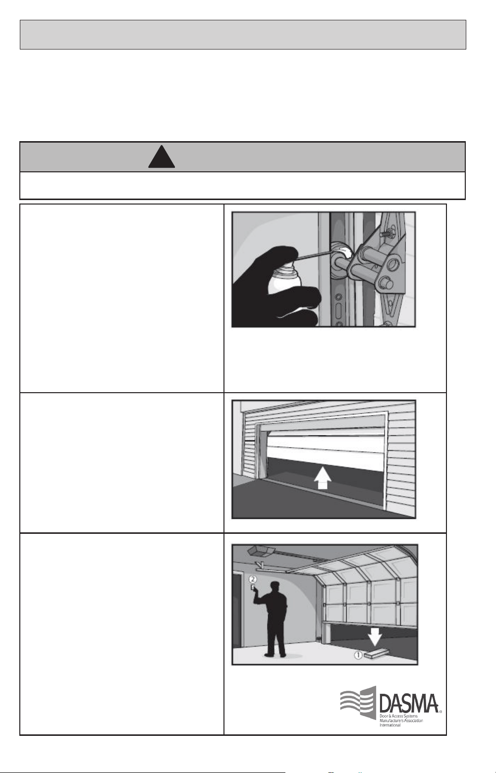
30
DASMA SAFETY GUIDELINES cont’dDASMA SAFETY GUIDELINES cont’d
Routine Maintenance Can Prevent Tragedies
Make monthly inspection and testing of your garage door and opener system a part of your regular routine.
Review your owner’s manual for both the door and door opener. If you don’t have the owner’s manuals, contact
the manufacturer(s) and request a copy for your specic model(s). Look for the opener model number on the back
of the power unit.
WARNING
!
Springs are under high tension. Do not loosen or adjust any bottom brackets, red colored fasteners, cables, or
supports. Only trained door system technicians should adjust these components.
Visually check the door and installation:
• Starting with the door in the closed position,
use the manual disconnect on the opener to
disconnect the door.
• Look for signs of wear or damage on hinges,
rollers, springs, and door panels.
• These parts may require periodic lubrication.
Check the owner’s manual for suggested
maintenance.
• If any signs of damage are evident, contact
a trained door systems technician for
assistance.
• Verify the photo eye height is no higher than
6” from the garage oor.
Test the door for proper operation:
• Open and close the door manually using
handles or suitable gripping points.
• The door should move freely and without
diculty.
• The door should balance and stay partially
open 3–4 feet above the oor.
• If you detect any signs of improper
operation, contact a trained door systems
technician for assistance.
Test the opener safety features:
• Reconnect the opener to the door using the
manual disconnect and open the door.
• Place a 2x4 board at in the path of the door
(1) and try to close it (2). The door should
stop when it comes in contact with the 2x4
and then reverse direction.
• Block the photoelectric sensor by waving an
object in front of the sensor and attempt to
close the door. The door should not close
unless the wall-mounted push button is
manually held during operation.
• If the opener does not perform as described,
contact a trained door systems technician
for assistance.