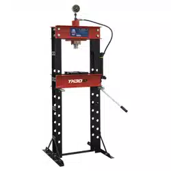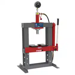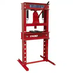
30 TONNE FLOOR TYPE HYDRAULIC PRESS
MODEL NO: YK30ECF
Thank you for purchasing a Sealey product. Manufactured to a high standard, this product will, if used according to these
instructions, and properly maintained, give you years of trouble free performance.
IMPORTANT: PLEASE READ THESE INSTRUCTIONS CAREFULLY. NOTE THE SAFE OPERATIONAL REQUIREMENTS, WARNINGS & CAUTIONS. USE
THE PRODUCT CORRECTLY AND WITH CARE FOR THE PURPOSE FOR WHICH IT IS INTENDED. FAILURE TO DO SO MAY CAUSE DAMAGE AND/OR
PERSONAL INJURY AND WILL INVALIDATE THE WARRANTY. KEEP THESE INSTRUCTIONS SAFE FOR FUTURE USE.
1. SAFETY
9 Familiarise yourself with the applications, limitations and hazards of the press.
9 Maintain the press in good condition (use an authorised service agent).
9 Replace or repair damaged parts. Use recommended parts only. Unauthorised parts may be dangerous and will invalidate the warranty.
9 Keep the press clean for best and safest performance.
9 Locate the press in an adequate working area for its function, keep area clean and tidy and free from unrelated materials and ensure there
is adequate lighting.
9 Ensure the work piece is correctly secured before operating the press.
9 Ensure that all fittings are tight before each use.
9 Remove ill fitting clothing. Remove ties, watches, rings, other loose jewellery and contain long hair.
9 Keep hands and body clear of the table when operating the press.
9 Maintain correct balance and footing. Ensure the floor is not slippery and wear non-slip shoes.
9 Keep children and unauthorised persons away from the working area.
9 Securely attach the press to a flat, firm, level surface capable of supporting the weight of press and any work piece taking into account
clearance for work pieces.
9 When not in use, release pressure from the hydraulic unit and clean the press. Stand or store the V blocks in a safe location.
8 DO NOT operate the press if any parts are missing as this may cause failure and/or possible personal injury.
8 DO NOT use the press for a task it is not designed to perform.
8 DO NOT make any modifications to the press.
8 DO NOT exceed the rated capacity of the press.
8 DO NOT apply off-centre loads.
8 DO NOT allow the work piece or the v blocks to fall from the table.
8 DO NOT get the press wet or use in damp or wet locations or areas where there is condensation.
8 DO NOT operate the press when you are tired or under the influence of alcohol, drugs or intoxicating medication.
8 DO NOT climb upon the press.
8 DO NOT use the press to compress a spring or any other item that could disengage and cause a potential hazard including personal injury.
8 DO NOT stand directly in front of a loaded press and never leave a loaded press unattended.
8 DO NOT allow untrained persons to operate the press.
WARNING! Always wear approved eye or face protection when operating the press. A full range of personal safety equipment is available
from your Sealey stockist.
WARNING: DO NOT top up hydraulic unit with brake fluid, or any other fluid other than a good quality hydraulic oil (Sealey Part Number:
HJO500MLS/HJO5LS) as this may cause serious damage to the hydraulic unit and will invalidate the warranty.
WARNING! Always position the press against a wall. If the press is situated in the open workshop, it is essential that a guard be
placed at the rear of the unit. This will prevent injury to bystanders in the event of the work piece ejecting suddenly.
WARNING! The warnings, cautions and instructions in this manual cannot cover all possible conditions and situations that may occur.
It must be understood by the operator that common sense and caution are factors which cannot be built into this product, but must be
applied by the operator.
▲ DANGER! The press is top heavy. If it requires moving after assembly or for relocation, use suitable slings around the top crossbeam,
or lift direct with a forklift with the forks located under the top crossbeam. DO NOT use a pallet truck.
2. INTRODUCTION
Made from a high quality steel with a powder coated paint finish to help corrosion resistance. Supplied in KD form.
3. SPECIFICATION
Model No: ......................................................... YK30ECF
Capacity: .............................................................30 Tonne
Gauge Included: ............................................................No
Maximum Height - Ram to Table: ...........................610mm
Minimum Height - Ram to Table: .......................... -265mm
Overall Height: .....................................................1500mm
Overall Width: .........................................................750mm
Ram Diameter: ......................................................Ø56mm
Ram Stroke: ...........................................................180mm
Table Aperture: .......................................................140mm
Total Ram Travel: ...................................................180mm
Type: ...................................................................Hydraulic
Working Table Depth: .............................................260mm
Working Table Width: .............................................655mm
Refer to
instructions
Wear a face
shield
Warning
crushing of
hands
Wear protective
gloves
Wear protective
clothing
Wear protective
footwear
Original Language Version
© Jack Sealey Limited
YK30ECF Issue 3 (H,3,F) 29/09/23
4. ASSEMBLY
Unpack the product and check contents. Should there be any damaged or missing parts contact your supplier immediately. Take care
when removing components from packing as these units are very heavy.
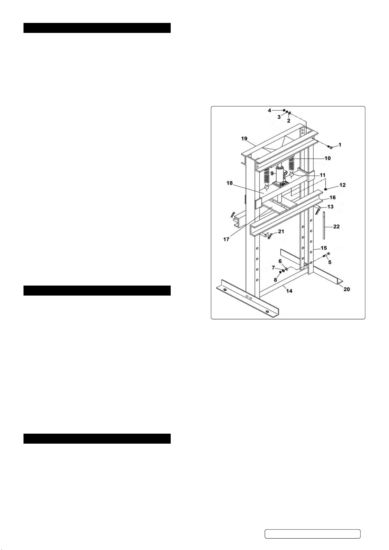
Part numbers below refer to attached Parts List.
Seek assistance of another person on assembly of heavy parts.
Assemble press, if possible, in close proximity to where the press will be located. Leave fixings loose until fully assembled then tighten to
ease assembly.
4.1. FRAME ASSEMBLY
4.1.1. With the assistance of another person start the horizontal assembly of the press on a bench, or similar.
4.1.2. Attach the base section (#20) to the upright (#15) and the base support (#14) using M12 x 35 screws (#5), M12 flat washer (#6), M12
spring washer (#7) and M12 steel nut (#8) loosely.
4.1.3. Repeat for the other side base section (#20).
4.1.4. With the assistance of another person, place the press in an upright
position and insert the pin, table support (#13) through the uprights
(#15).
4.1.5. Taking care, lift the table (#16) over the uprights and lower onto the
pins, table support (#13). Insert pins (#21).
WARNING! Take care not to allow the table to drop onto the table
pins and ensure your hands and fingers are kept clear.
4.1.6. Taking care, lift the upper support upper support (#19) into position
and secure using M16 x 35 hex head screws (#1), M16 flat washers
(#2) and M16 spring washers (#3) attach M16 steel nuts (#4) loosely.
4.1.7. Stand the part assembled press frame onto a flat, level floor and level
the frame using a good quality level. Fully tighten all the bolts.
4.2. ATTACHING THE SUPPORT PLATE
4.2.1. Locate the Hook pin (#11) into the support plate (#18) and secure
using M8 steel nuts (#12) loosely.
4.2.2. Hook the springs (#10) to the round bars on the underside of the
upper support (#19).
4.2.3. Taking firm hold of the support plate (#18) tip it into a diagonal
position so it can be introduced between the uprights (#15). When
level attach the hook pins (#11) to the springs (#10).
4.2.4. Adjust the length of the hook pins (#11) using the M8 steel nuts (#12)
so that the support plate (#18) is parallel to the upper support (#19).
4.3. THE HYDRAULIC UNIT
4.3.1. Insert handle (#22) into handle sleeve on the hydraulic unit (#9).
4.4. Place the arbor plates (#17) onto the table (#16).
5. INSTALLATION
5.1. SECURE THE PRESS TO THE FLOOR
WARNING! Always use the assistance of another person when
moving the press.
5.1.1. Move the press to the mounting location and spot mark through fixing
holes in base section (#20) onto the floor.
5.1.2. Check for any hidden wiring or cables, if needed change the location for the holes.
5.1.3. Temporarily move the press to the side.
5.1.4. Use a masonry drill bit to drill the four holes about 3” to 4” deep into the concrete or wood, as necessary.
5.1.5. Clean out the drilled holes.
5.1.6. Position the press and align the holes in the base section with the holes in the floor.
5.1.7. Use four concrete anchor bolts or lag bolts for wooden floors, (not included), to secure to the floor.
WARNING! To prevent serious injury DO NOT use damaged equipment. If abnormal noise or vibration occurs have the problem corrected.
5.2. BEFORE FIRST USE
5.2.1. Before operating the press, purge the hydraulic system of the hydraulic unit (#6), in order to eliminate any air that may have accumulated
during transit. Open the release valve and pump the handle several times and close the release valve. Should the system malfunction at
any time, repeating this process may resolve the problem.
▲ DANGER! This model is purposefully designed to withstand greater loads than the hydraulic units can develop. For safety reasons,
always ensure the work piece and press tools are secured on the table and will not flex or suddenly “give way” causing danger to operator
or the component. Also ensure you have read and understood section 1 safety instructions.
6. OPERATION
6.1. Check that the hydraulic unit is fully closed ready for operating.
6.1.1. Position the table at the required operating height by inserting the pins into the appropriate holes in the frame.
6.1.2. Position the V blocks or press tools to be used onto the table and align beneath the ram. Place work piece onto the table or V blocks and
align beneath the ram as required. Note: Care must be taken to ensure a V block does not fall from the press table. If necessary hold the
configuration in position with clamps (not supplied).
6.1.3. Operate the pump slowly until the ram is close to or just touching the work piece. Before applying real pressure to the work piece recheck
the alignment with the ram and ensure that the work piece and press tools are supported in such a way that they cannot flex to breaking
point. DO NOT exceed the stroke indicated on the label or the red mark on the piston and DO NOT apply off centre loads.
6.1.4. When work is complete release the pressure by fitting the handle over the release valve and turning anti-clockwise in small increments.
6.1.5. Once the hydraulic unit has been fully retracted, remove the work piece from the V blocks and the table.
Note: Always keep the piston retracted after use to avoid corrosion.
Original Language Version
© Jack Sealey Limited
YK30ECF Issue 3 (H,3,F) 29/09/23

Original Language Version
© Jack Sealey Limited
YK30ECF Issue 3 (H,3,F) 29/09/23
Sealey Group, Kempson Way, Suffolk Business Park, Bury St Edmunds, Suffolk. IP32 7AR
01284 757500 sales@sealey.co.uk www.sealey.co.uk
Note: It is our policy to continually improve products and as such we reserve the right to alter data, specications and component parts without prior notice.
Important: No Liability is accepted for incorrect use of this product.
Warranty: Guarantee is 12 months from purchase date, proof of which is required for any claim.
ENVIRONMENT PROTECTION
Recycle unwanted materials instead of disposing of them as waste. All tools, accessories and packaging should be
sorted, taken to a recycling centre and disposed of in a manner which is compatible with the environment. When
the product becomes completely unserviceable and requires disposal, drain any uids (if applicable) into approved
containers and dispose of the product and uids according to local regulations.
REGISTER YOUR
PURCHASE HERE
7. MAINTENANCE
Note: Maintenance and repair must only be carried out by qualified person. Contact your Sealey stockist for details.
7.1. When the press is not in use, the hydraulic unit ram must be fully retracted to minimise corrosion. Remove the handle to inactivate the
press.
7.2. Lubricate all moving parts at regular intervals.
7.3. Always keep the press clean, dry, and protected from harsh conditions.
7.4. Should you need to replace the oil, ensure the hydraulic unit ram is fully retracted. An excess of oil will render the press inoperative.
7.5. Use only appropriate Sealey hydraulic jack oil (Sealey Part Number: HJO500MLS/HJO5LS). DO NOT use brake fluid. Purge the system to
remove any air.
7.6. Check your model parts information for spares.
IMPORTANT: NO RESPONSIBILITY IS ACCEPTED FOR INCORRECT USE OF THE MACHINE.
Hydraulic products are only repaired by local service agents. We have service/repair agents in all parts of the UK.
DO NOT return product to us. Please telephone us on 01284 757500 to obtain the address and phone number of your local agent.
If product is under guarantee please contact your dealer. Should the product become completely unserviceable and require disposal,
draw o the oil into an approved container and dispose of the product and the oil according to local regulations.