Loading ...
Loading ...
Loading ...
ASSEMBLY INSTRUCTIONS
9
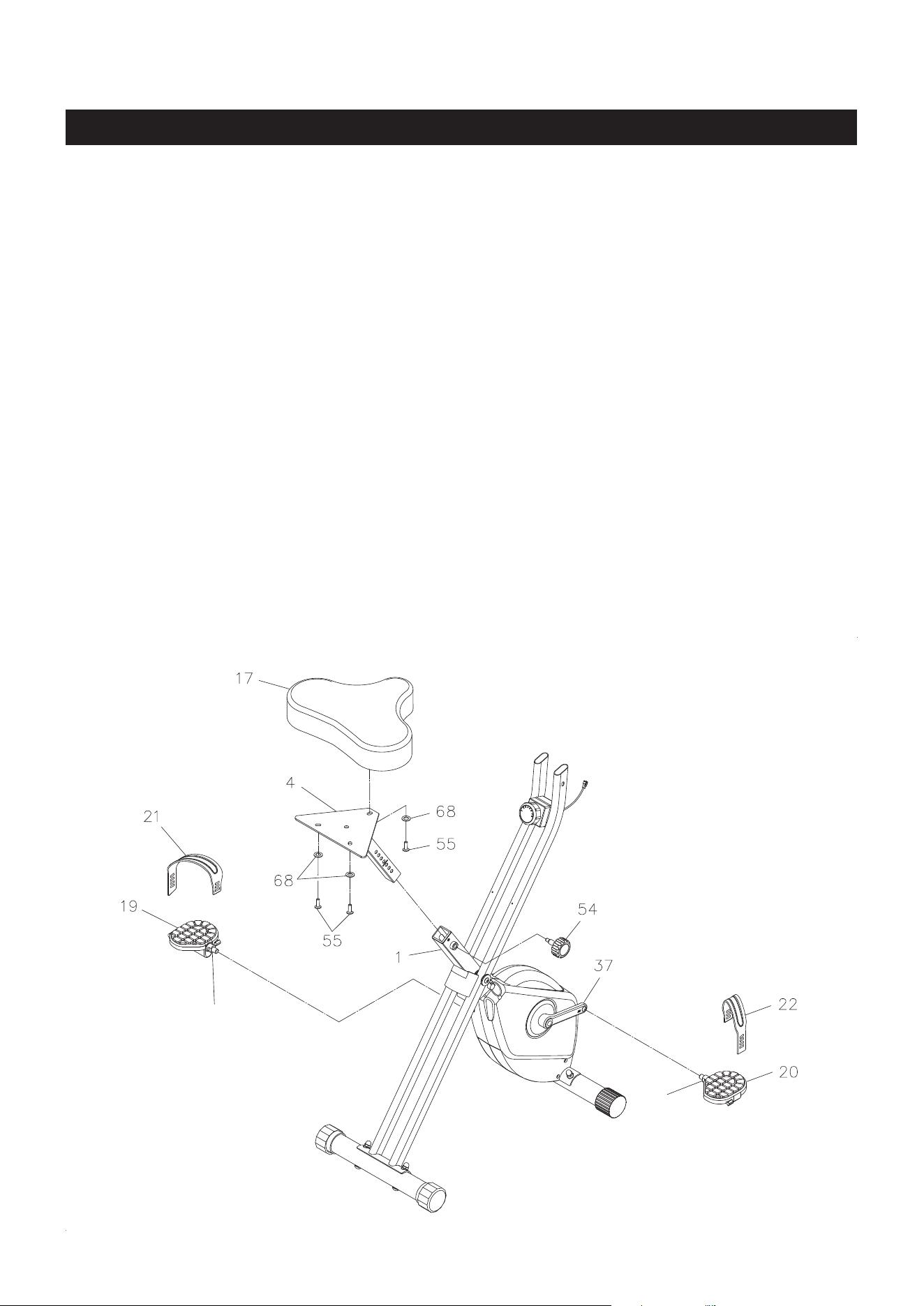
STEP 4
NOTE: The RIGHT PEDAL(20) has an R stamped on the end of the pedal shaft. The RIGHT PEDAL(20)
has right hand threads and is tightened by turning clockwise. The LEFT PEDAL(19) has an L
stamped on the end of the pedal shaft. The LEFT PEDAL(19) has left hand threads and is tightened
by turning counterclockwise.
Thread the RIGHT PEDAL(20) to the RIGHT CRANK(37) as shown. Tighten the pedal securely. The
shoulder of the PEDALS(19, 20) should be in contact with the CRANKS(36, 37) when securely tightened.
Select the RIGHT PEDAL STRAP(22) which has an R marked on the bottom side of the strap. Snap the
three hole end to the inside edge of the RIGHT PEDAL(20). Snap the other end to the outside edge of the
RIGHT PEDAL(20) with the R mark on the bottom of the RIGHT PEDAL STRAP(22). Select adjustment
holes which allow your foot to be easily removed from the pedals.
Repeat on the left side in order to attach the LEFT PEDAL(19) to the LEFT CRANK(36) and snap the LEFT
PEDAL STRAP(21) to the LEFT PEDAL(19).
STEP 5
Attach the SEAT(17) to the SEAT POST(4) with BUTTON HEAD BOLTS(M8x1.25x20mm)(55) and
WASHERS(M8)(68). Insert the SEAT POST(4) into the MAIN FRAME(1) and secure with the ADJUSTMENT
KNOB(54).
NOTE: Make sure that the pin on the ADJUSTMENT KNOB(54) is inserted into one of the holes in the
SEAT POST(4). The ADJUSTMENT KNOB(54) should be screwed in tight to make the SEAT
POST(4) t securely in the MAIN FRAME(1).
Shoulder
Shoulder
Loading ...
Loading ...
Loading ...