Before using your air conditioner, please read this manual carefully and
keep it for future reference, along with your receipt.
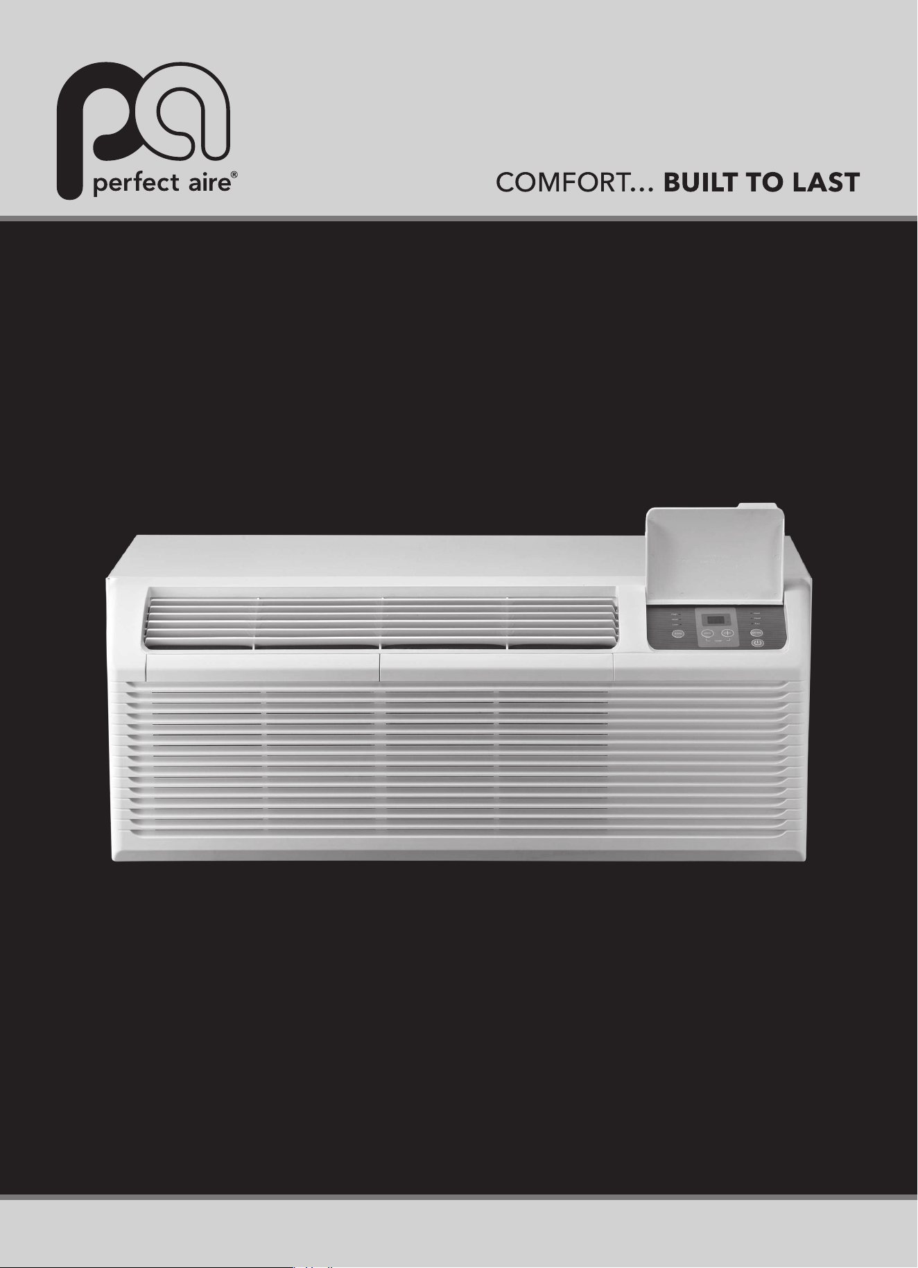
PACKAGED TERMINAL
AIR CONDITIONER
USER MANUAL
FOR MODELS:
3PTC07A-HE-3.5
3PTC09A-HE-3.5
3PTC12A-HE-3.5
3PTC12A-HE-5.0
3PTC15A-HE-3.5
3PTC15A-HE-5.0
3PTH07A-HE-3.5
3PTH09A-HE-3.5
3PTH12A-HE-3.5
3PTH12A-HE-5.0
3PTH15A-HE-3.5
3PTH15A-HE-5.0

NOTE: All the illustrations in this manual are for explanation and reference purposes only.
Unit purchased may be slightly different.
The design and specifications are subject to change without prior notice for product
improvement. Contact customer service for details.
1
SAFETY PRECAUTIONS ..................................................................................... 2
IMPORTANT SAFETY INSTRUCTIONS ...............................................................4
AIR CONDITIONER FEATURES.......................................................................... 5
CONTROL PANEL OPERATION .........................................................................4
DIP SWITCH CONFIGURATION
.......................................................................... 7
INSTALLATION ...................................................................................................10
CARE AND CLEANING...................................................................................... 12
TROUBLESHOOTING TIPS ............................................................................... 13
This manual provides the information needed for proper use and maintenance of this air
conditioner. Basic preventative care can help extend the life of this unit. The “Troubleshooting
Tips” section in this manual contains a chart with solutions to the most common problems.
Referring to this section may save time and prevent the need for a service call in the event of
a problem.
!
CAUTION
● Contact an authorized service technician for installation, repair or maintenance of this unit.
● If power cord is damaged and requires replacement, the work should be performed by
authorized service personnel only.
● Installation and repair work must be performed in accordance with national wiring standards
by authorized personnel only.
● Do not operate your air conditioner in a room such as a bathroom or laundry room where
direct or indirect exposure to water is possible.
● All units have a heating function and must be at least 3 1/2 ft (1 meter) away from
combustible and flammable materials.
● The air conditioner is not intended for use by young children without supervision.
Young children should be supervised to ensure that they do not play with the air conditioner.
● Disabled persons may require assistance with set up.
CONTENTS
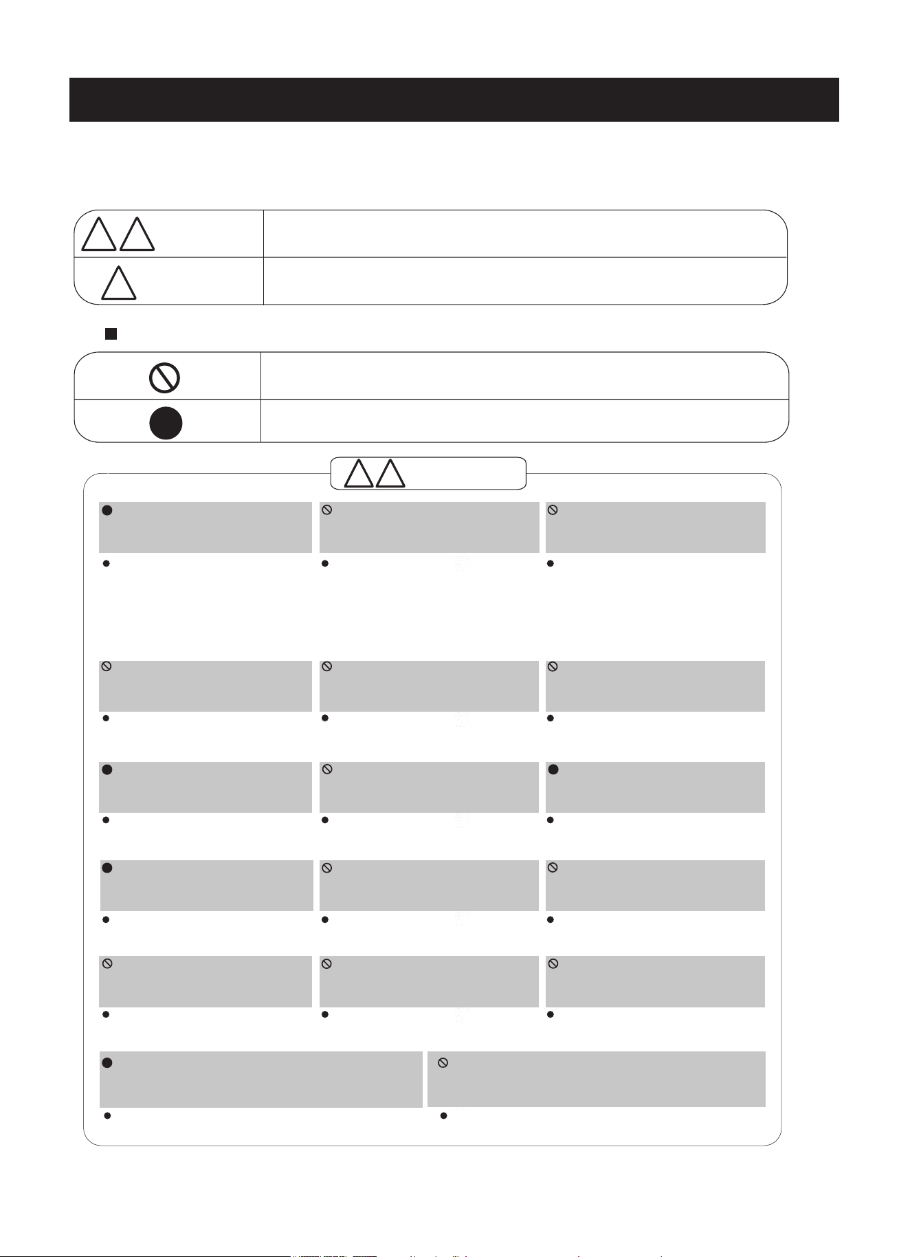
To prevent injury to the user or other people and property damage, the following instructions
must be followed. Ignoring instructions or incorrect operation of unit may cause harm to
individuals and damage to the unit. The seriousness is classified by the following indicators.
SAFETY PRECAUTIONS
This symbol indicates the possibility of death or serious injury.
Meaning of symbols used in this manual are as shown below.
!
Always do this.
Never do this.
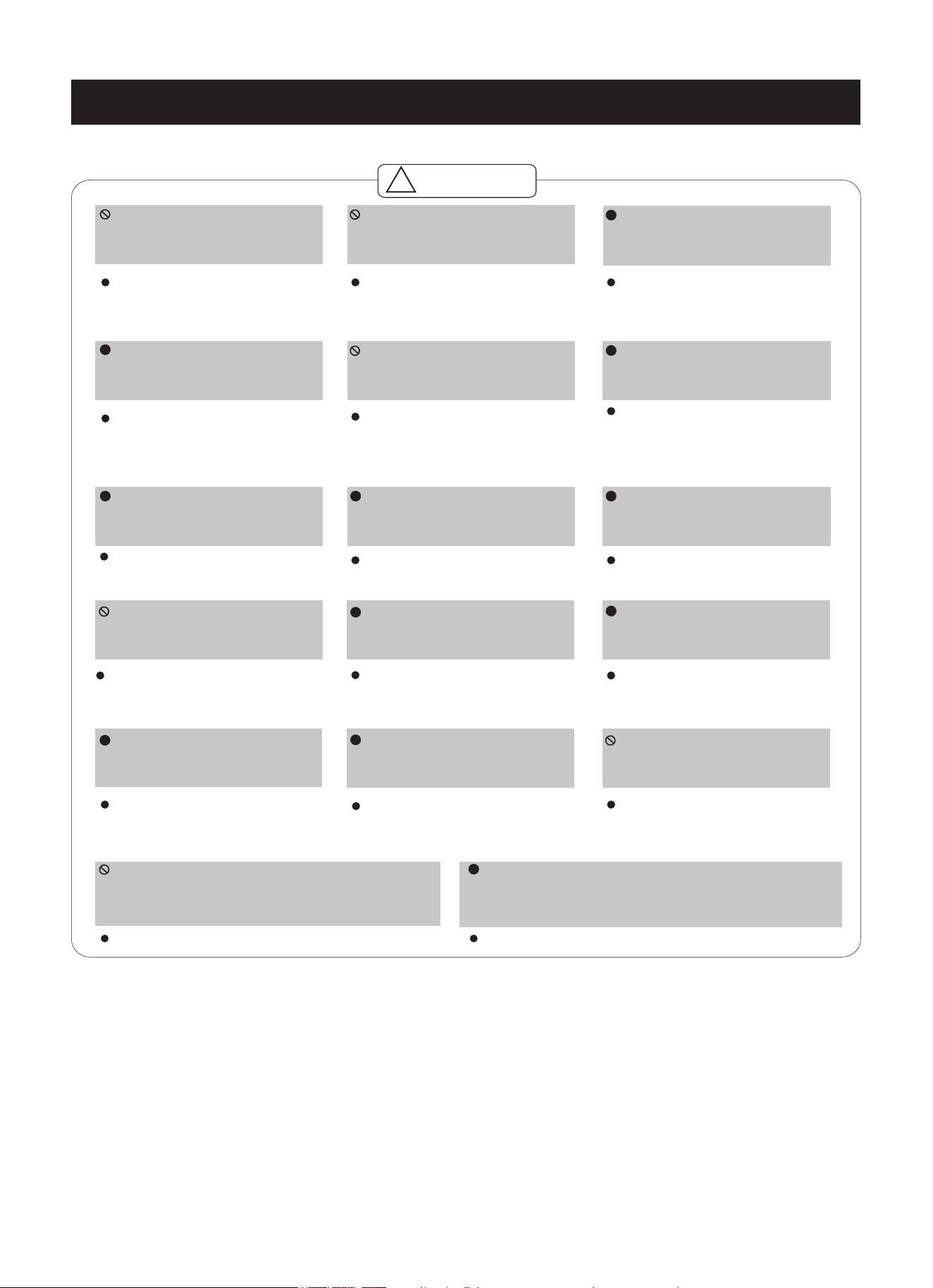
CAUTION
This symbol indicates the possibility of injury or damage to property.
Plug in power plug properly.
Do not modify power cord in
any way. Outlet must be
dedicated to air conditioner only.
Always ensure effective
grounding.
Always unplug the unit if
strange sounds, smell or
smoke comes from the unit.
Do not use firearms near unit.
Room must be properly ventilated before
operating air conditioner. Never operate if there is
a gas leak from another appliance such as a stove.
Failure to do so may cause
electric shock or fire due to
excess heat generation
.
Doing so may cause electric
shock or fire due to heat
generation.
Incorrect grounding may cause
electric shock.
Failure to do so may cause fire
and electric shock.
Doing so may cause fire.
Failure to do so may cause explosion, fire and burns.
Doing so may cause electric
shock or fire due to heat generation.
Doing so may cause electric shock.
Doing so may cause failure of
machine or electric shock.
Doing so may cause fire and
electric shock.
Doing so may cause fire and
electric shock.
Doing so may cause electric shock
or fire. If the power cord is
damaged, it must be replaced by
the manufacturer or an authorized
service center or a similarly
qualified person.
This could be uncomfortable and
cause health issues.
Incorrect installation may cause fire
and electric shock.
Doing so may cause electric shock.
Doing so may cause an explosion or fire.
Doing so may cause failure and
electric shock.
Do not power unit on/off solely
by plugging/unplugging unit’s
plug into/from the power outlet.
Do not operate with wet hands
or in damp environment.
Do not allow water to run into
electric parts.
Do not use the socket if it is
loose or damaged.
Do not use the power cord close
to heating appliances.
Do not use a damaged power
Do not direct airflow directly at
room occupants.
Always install circuit breaker
and a dedicated power circuit.
Do not open the unit during
operation.
Do not disassemble, modify,
or drill holes into the air
conditioner.
!
!
!
!
!
WARNING
! !
!
! !
!
cord.
Do not use the power cord near flammable gas
or combustibles, such as gasoline, benzene,
thinner, etc.
!
!!
!
!
WARNIN
G
2
3
When removing air filter, do not
touch metal parts of the unit.
Doing so may cause an injury.
.
Cleaning unit when power is ON
may cause fire and electric shock
and may cause an injury.
Operation with windows open may
cause moisture to enter the room.
Stop operation and close the
window in severe storms or
hurricanes.
Do not clean with water.
Water may enter the unit and
degrade the insulation causing an
electric shock.
This could injure the pet or plant.
Failure to do so may cause electric
shock and damage.
Do not put a pet or house plant
where it will be exposed to
direct air flow.
Hold the plug by the head of the
power plug when taking it out.
Ensure proper ventilation
especially in rooms with a stove
or other appliances.
Failure to do so may result in an
oxygen shortage.
This unit is NOT intended to
preserve precision devices, food,
pets, plants, and art objects. It may
cause deterioration of quality, etc.
Leaving power on may cause unit
failure or fire.
Use only as intended.
If unit will not be used for a long
period of time, turn OFF main
power switch.
If water enters the unit, turn the unit off at the power
outlet and switch off the circuit breaker. Isolate supply
by taking the power-plug out and contact a qualified
serviced technician.
Obstacles may cause appliance
failure or accident.
Cleaners or detergents may change
the color or scratch the surface of
the unit.
Do not place obstacles around
air-inlets or inside of air-outlet.
Use only a soft cloth to clean
the unit.
Prolonged exposure to outdoor
elements may cause damage to
installation bracket causing unit to
fall.
There is danger of electric shock.
Periodically check installation
bracket for damage.
.
Operation without secured filters
may cause failure. A dirty filter
can cause the unit to not run
efficiently.
Water from unit contains
contaminants and could cause
illness.
Always insert the filters securely.
Clean filter AT LEAST once
every two weeks.
NEVER drink water drained from
air conditioner.
Unit and Circuit breaker/fuse
must be switched OFF when
cleaning.
Do not place heavy objects on the power cord
and always ensure that the cord is not
compressed.
Use caution when unpacking
and installing.
Sharp edges could cause injury.
!
!
!! !
!
!
!
!
!
!
There is danger of fire or electric shock.
!
CAUTION
SAFETY PRECAUTIONS (CONTINUED)
IMPORTANT SAFETY INSTRUCTIONS
Be sure the electrical service is adequate for the model you have chosen.
This information can be found on the serial plate, which is located on the
side of the cabinet and behind the grille.
Be sure the air conditioner is properly grounded. To minimize shock and fire
hazards, proper grounding is important. The power cord is equipped with a
three-prong grounding plug for protection against shock hazards.
Your air conditioner must be used in a properly grounded wall receptacle. If
the wall receptacle you intend to use is not adequately grounded or
protected by a time delay fuse or circuit breaker, have a qualified electrician
install the proper receptacle.
Ensure the receptacle is accessible after the unit installation.
Do not run air conditioner without side protective cover in place. This could
result in mechanical damage within the air conditioner.
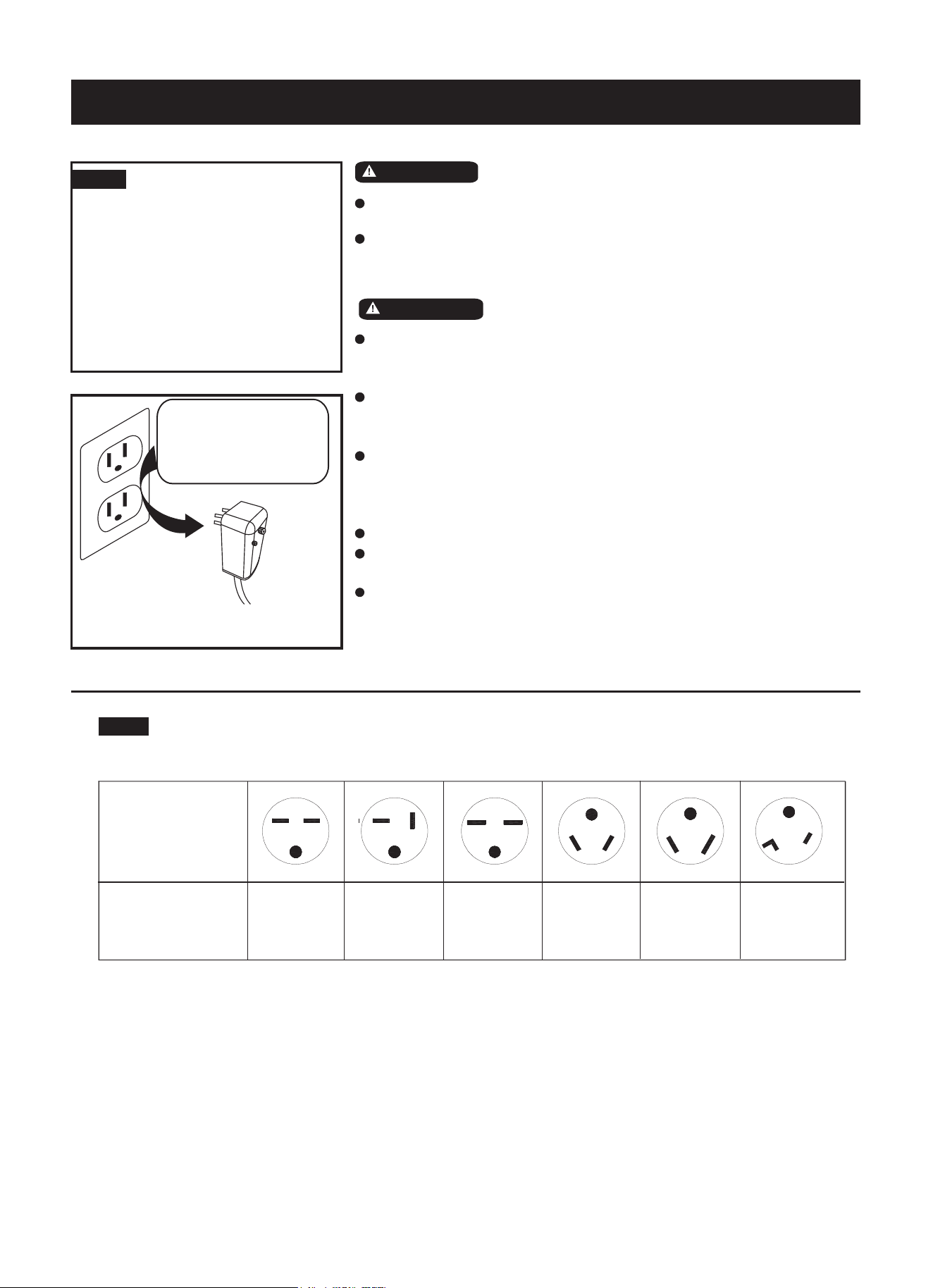
Do not use an extension cord or an adaptor plug.
WARNING!
DO NOT store or use gasoline or other flammable vapors or liquids in
the vicinity of this or any other appliance.
Avoid fire hazard or electric shock. DO NOT use an extension cord or
an adaptor plug. DO NOT remove any prong from the power cord.
WARNING!
NOTE
The power supply cord with this
this air conditioner contains a current
detection device designed to reduce the
risk of fire. Please refer to the section
"Operation of Current Device" (next
page) for details. In the event that the
power cord is damaged, it MUST be
replaced with a power cord from the
product manufacturer. Cord replacement
must be performed by an authorized
technician.
DO NOT, under any
circumstances, cut,
remove, or bypass
grounding prong.
Power supply cord
with 3-prong grounding plug
and current detection device
For Your Safety
Electrical Information
4
NOTE:
The shape may be different based on the specific model selected:
Power Card
Power Supply
230V,15A 230V,20A 230V,30A 265V,20A 265V,30A265V,15A
AIR CONDITIONER FEATURES
This unit has many features. The servicer must be
familiar with these features in order to properly
service the unit.
● Compressor Restart Delay
This feature extends the overall life of the
compressor by preventing the short-cycling of the
air conditioner. When the compressor restarts, the
unit is designed to have a delay of at least three
minutes to have enough time to equalize the
refrigerant pressures for optimal cycling.
● Memory
The unit has memory. If power is lost, all of the
control settings (mode, fan speed, on/off and
configuration) are remembered. When power is
restored, the unit will start back up in the mode
(and configuration) it was in when power was lost.
● Automatic Evaporator Freeze Protection
To keep the evaporator from freezing when the
evaporator temperature is too low, the compressor
is automatically turned off and indoor fan is
turned on.
● Automatic Quick Warm-up
(For Heat Pump Models Only)
If the room temperature falls to 8ºF/4.5ºC below
the set point temperature, the reverse cycle heat
is shut off and the electric strip heat is turned on
for one cycle until heating is satisfied.
● LED Indicators and Buttons
The touch pad has buttons for MODE, FAN,
POWER, SETPOINT UP and SETPOINT DOWN.
It also has LEDs that correspond to the mode, fan
speed, power and setpoint operation to indicate
the unit’s status.
LEDs for HIGH, MED, and LOW indicate the fan
speed that is selected.
LEDs for FAN, COOL and HEAT indicate what
operating mode is active.
The LED for POWER indicates the unit’s
ON/OFF status.
- If the unit is in ON mode, the LED will be green.
- If the unit is OFF, the LED will be off.
Note: HEAT mode is for models with Cooling &
Heating functions only.
● High Temperature Protection in
Heating Operation
The compressor and/or electric heater will be
switched off to prevent damage where high indoor
air temperatures are present or if an error is
detected by the indoor temperature sensor. See
“HI” code on page 6.
● Unit Configuration - ºF or ºC
The unit can display in either ºF or ºC.
5
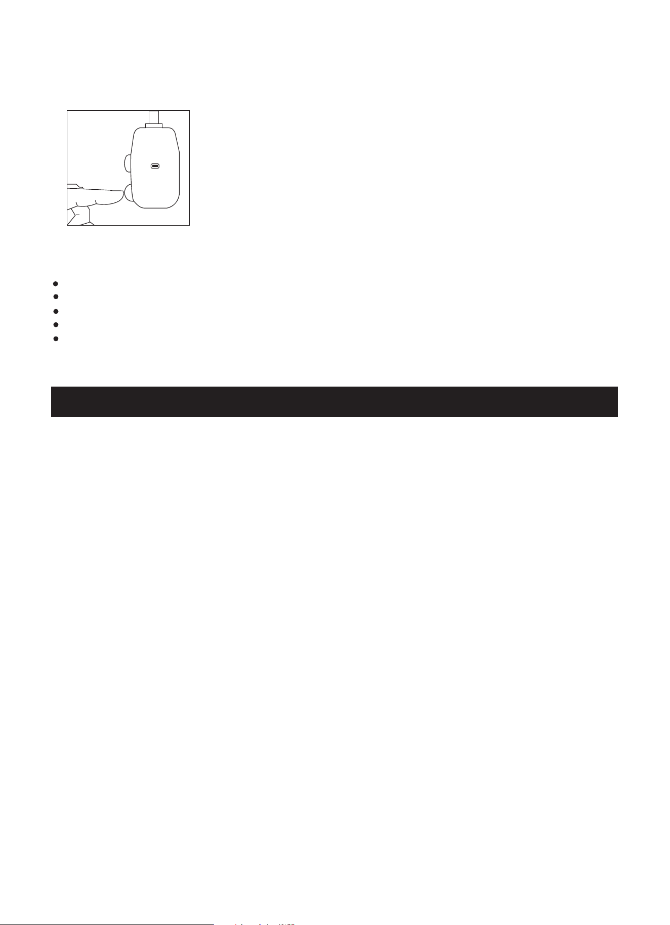
Operation of Current Device (Optional)
1. Plug in the air conditioner.
2. The power supply cord will have TWO buttons on the plug head. Press the TEST
button. The RESET button will click as it pops out.
3. Press the RESET button; again you will notice a click as the button engages.
4. The power supply cord is now supplying electricity to the unit.
(On some products this is also indicated by a light on the plug head.)
NOTES:
Do not use this device to turn the unit on or off.
Always make sure the RESET button is pushed in for correct operation.
If power supply cord is damaged, it cannot be repaired. Please call customer service to assist with replacement.
When 265V units are installed, the power supply must be permanent wiring. Permanent wiring may be done through
the accessory subbase. An exposed cord conection on 265V units is not permitted.
TEST
RESET
Plug in &
press RESET
NOTE: Some plugs have
buttons on the top.
The power supply cord contains a current device that senses damage to the power
cord. To test your power supply cord do the following:
The power supply must be replaced if it fails to reset when either the TEST button is pushed or it cannot be reset.
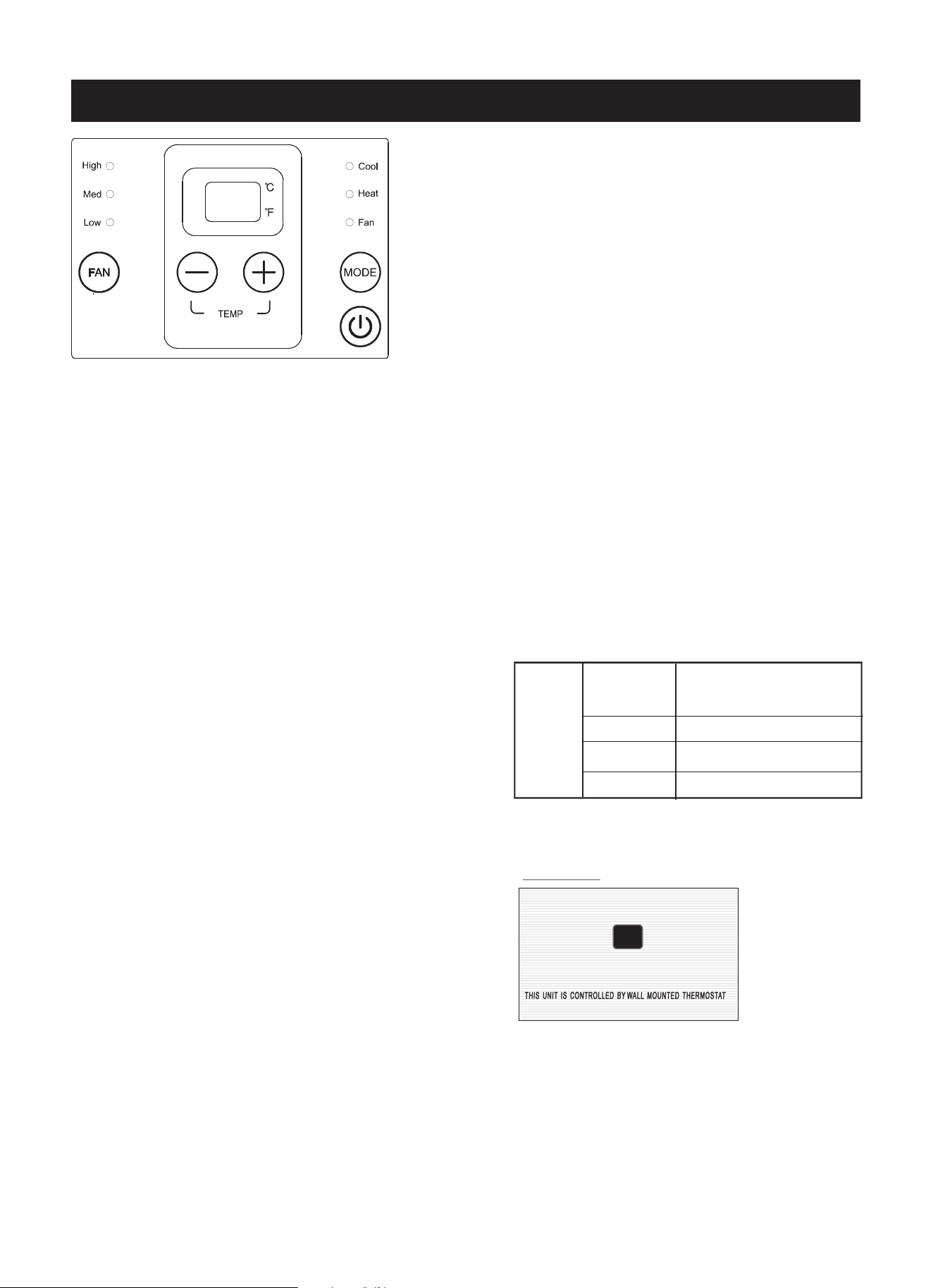
CONTROL PANEL OPERATION
Fig.1
NOTE: All of the pictures in this manual are for explanatory purposes only. The actual shape/look of the
air conditioner purchased may be slightly different, but the operations and functions are similar.
● POWER
Press the POWER button to turn the unit on or off.
When the unit is on, the power indicator light will
be green. When the unit is off, the light will go out.
● MODE
Push this button to cycle through the modes from
COOL-HEAT-FAN-COOL. The indicator light
beside the “MODE” option will illuminate,
identifying the mode selected.
COOL: The range of set temperatures is
62°F/17°C–86ºF/30°C. Cooling begins
automatically when the room temperature is
above the set point, and stops when the room
temperature is 4°F/2°C below the set point. The
compressor will run a minimum of 5 minutes in
COOL mode before stopping. The fan runs
continuously in continuous mode.
HEAT: The range of set temperatures is
62°F/17°C–86ºF/30°C. For heat pump models, the
unit can alternate to run between reverse cycle
heat mode and electric heat mode according to
the difference between the set temperature and
room temperature.
NOTE: The reverse cycle and electric heater
cannot be run at the same time.
FAN: Fan operation only; no heating/cooling.
● UP/DOWN BUTTONS ( + / – )
Push the “+” or “–” button to increase or decrease
the set temperature of the unit in cooling or
heating mode. The temperature can be set by
increments of 1ºF (1ºC). The temperature setting
appears in the display.
NOTE: Press and hold the “+” and “–” buttons
together for 3 seconds to alternate between the °F
and °C settings.
● FAN (FAN SPEED)
Every time you push this button the fan speed
cycles through the settings as follows:
HIGH → MED → LOW → HIGH.
● DISPLAY
Shows the set temperature in ºF or ºC. While in
Fan only mode, it shows the room temperature.
Control Code (some models):
LC - Pads on the control panel are not available.
The unit can only be set by using the wired
controller.
Error Codes:
AS - Room temperature sensor error
ES - Evaporator temperature sensor error
CS - Condenser temperature sensor error
OS - Outside temperature sensor error
HS - Exhaust temperature sensor error
NOTE: When error occurs, unplug the unit and
plug it back in. If error repeats, call for service.
Other Codes:
LO - Room temperature is lower than 32ºF/0ºC
HI - Room temperature is higher than 99ºF/37ºC
Accessory
NOTE: When the unit displays LC, function of
control panel is not available.The unit is controlled
by wired thermostat only. You can install this
Accessory on the control panel.
6
NOTE:
NOTE: Performance may be reduced outside of
these operating temperatures.
This air conditioner is designed to be
operated under condition as follows:
Cooling
operation
Outdoor temp:
64-109ºF/18-43ºC (64-125ºF/18-52ºC
for special tropical models)
Indoor temp:
Heating
operation
Outdoor temp:
Indoor temp:
62–90ºF/17–32ºC
23–76ºF/
-
5–24ºC
32–80ºF/0–27ºC
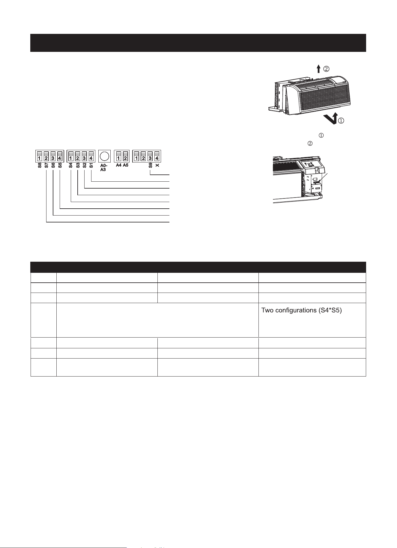
DIP SWITCH CONFIGURATIONS
Fig. 2
- Pull out at the bottom to release
it from the tabs .
- Then lift up .
UP (ON)
DOWN (OFF)
Fig. 4
Dip Switches
Fig. 3
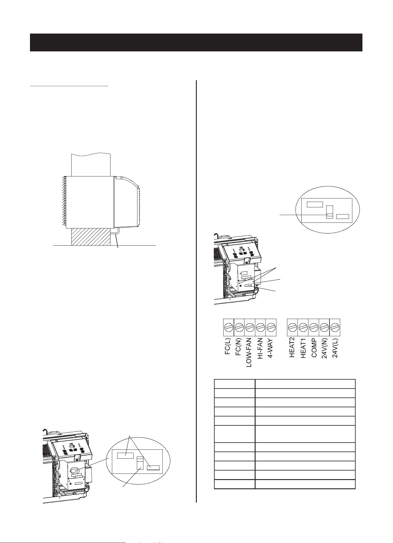
● REMOVING THE FRONT PANEL
- Dip switch controls are located behind the front panel through
an opening below the control panel. To access, remove the
front panel. See Fig. 2.
- Dip switches are accessible without opening the control box.
See Fig. 3.
- Unit must be powered OFF to effectively change their status.
● DIP SWITCH CONFIGURATIONS
- See Table 1 and Fig. 4 for Dip Switch configurations and
functions of each dip switch position.
NOTE: On heating mode, the setting temperature
cannot be higher than 84ºF/29ºC.
● Electric Heat Only (for heat pump unit only)
This setting is typically used for emergency heating.
● Enable Wall Thermostat
A wired wall themostat can be connected to the
unit. If one is connected, this dip switch must be
moved to the Enable Wall Thermostat position
before the wall thermostat will begin control.
● Setpoint Temperature Limits
Provides a restricted range of temperature control.
● Heat and Cool Fan CON/CYC Dip-switches
Allows the fan to operate in continuous or cycle
mode while the unit is in heating and cooling mode.
CON (Continuous)
Allows the fan to run continuously, circulating air
even when the temperature setting has been
satisfied. This switch helps to maintain the room
temperature closer to the thermostat setting.
CYC (Cycle)
This setting allows the fan to cycle on and off with
the compressor or electric heater. The fan stops a
short time after the temperature setting is satisfied.
Wall thermostat type
Heating type
Temperature display type
Control type
Setpoint limit 1
Setpoint limit 2
Fan CON/CYC for heating
Fan CON/CYC for cooling
Table 1 – DIP SWITCH CONFIGURATIONS
No. UP (ON) DOWN (OFF) Notes
S1 Electric Heat Only Electric Heat and Pump Heat For Heat Pump unit only
S2 Temperature Display in °C Temperature Display in °F
S3 Enable Wall Thermostat Enable Control Panel
S4*S5
S4 UP (ON) & S5 UP (ON) = 61°F–86°F (16°C–30°C);
S4 UP (ON) & S5 DOWN (OFF) = 65°F–78°F (18°C–26°C)
S4 DOWN (OFF) & S5 UP (ON) = 63°F–80°F (17°C–27°C);
S4 DOWN (OFF) & S5 DOWN (OFF) = 68°F–75°F (20°C–24°C)
combine to select set point range.
S6 Fan Continuous Run for Heating Fan Cycle for Heating
S7 Fan Continuous Run for Cooling Fan Cycle for Cooling
S9 Manufacturer’s wall thermostat
Approved universal
wall thermostat
Consult with the sales agency or
manufacturer for details.
7
8
IMPORTANT: Only trained, qualified personnel should access electrical panel on unit and install electrical
accessories. Please contact your local electrical contractor, dealer, or distributor for assistance.
Thermostat Wire Routing
NOTE:
Thermostat wire is field supplied. Recommended
wire gauge is 18 to 20 gauge solid thermostat wire.
It is recommended that extra wires are run
to unit in case any are damaged during installation.
Thermostat wire should always be routed around
or under, NEVER through, the wall sleeve. The
wire should then be routed behind the front panel
to the easily accessible terminal connector.
THERMOSTAT WIRE ROUTING
(UNDER SLEEVE, BEHIND FRONT PANEL)
Fig. A - Proper Wire Routing Beneath Unit
NOTE: Refer to thermostat installation instructions
for details on installing wall thermostat.
Terminals for manufacturer
provided wall thermostat
*S9 dip switch in
OFF (DOWN)
position.
*S9 dip switch in
ON (UP) position.
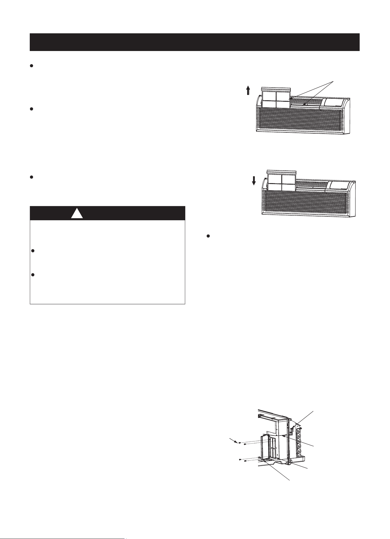
Remove the two screws
Cover panel
Terminals for universal
wall thermostat
WALL THERMOSTAT TERMINAL
INSTALLATION OF WALL THERMOSTAT PROVIDED
BY THE AIR CONDITIONER’S MANUFACTURER
NOTE: When installing a thermostat provided by the
air conditioner’s maufacturer, refer to the specific
instructions included with the thermostat.
IMPORTANT NOTE: When installing a thermostat
provided by the air conditioner’s manufacturer, the
S9 dip switch must be in the ON (UP) position.
Insert the wire connector of the wall thermostat into
the relevant terminal according to different shape as
shown below.
INSTALLATION OF UNIVERSAL
WALL THERMOSTAT
NOTE: When installing a universal wall thermostat,
refer to the specific instructions included with the
thermostat chosen.
IMPORTANT NOTE: When installing a universal
wall thermostat, the S9 dip switch must be in the
OFF (DOWN) position.
Remove the two screws as shown below to access
the terminals behind the cover panel.
TERMINAL DESIGNATION
FC(L) Front desk control terminal L
FC(N) Front desk control terminal N
LOW-FAN Low fan speed
HI-FAN High fan speed
4-WAY
4-way valve
(For heat pump system)
HEAT2 Electrical heater 2
HEAT1 Electrical heater 1
COMP Compressor
24V(N) 24VAC terminal N
24V(L) 24VAC terminal L
!
CAUTION
Failure to follow this caution may result in
equipment damage or improper operation.
Improper wiring may damage unit electronics.
Common busing is not permitted. Damage or
erratic operation may result.
UNIT DAMAGE HAZARD
WALL THERMOSTAT TERMINAL (Continued)
NOTE:
● Use terminal 4-way for heat pump connection only.
● If the chosen thermostat has a compressor
protection time delay function, it should be set for
a delay of greater than three minutes.
● Wall thermostat must be heating changeover
4-way valve.
● For thermostats that have only one fan speed
output (on or auto), the fan speed is determined by
how the terminal connector is wired. If Low fan is
desired, wire the G output from the thermostat to
LOW-FAN on the unit’s terminal block. If High fan
is desired, wire the G output from the thermostat
to HI-FAN on the unit’s terminal block.
● The range of set temperature of the wall
thermostat must be in accordance with the unit
type: heat pump or no heat pump.
● If the wall thermostat has only one electrical
heater output, connect the two terminals of HEAT
1 and HEAT 2; the unit can operate two electrical
heaters (units with two electrial heaters only).
Otherwise, operate one electrical heater.
● Please do not remove the control panel.
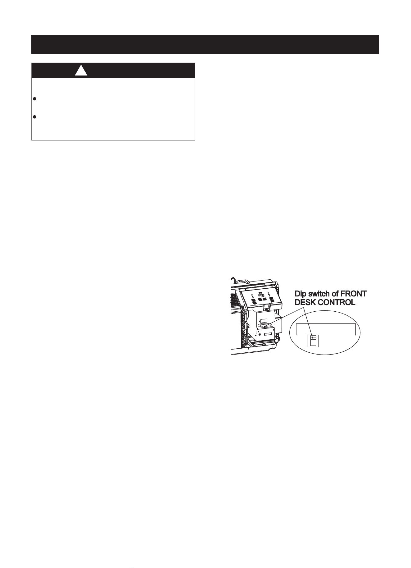
● FRONT DESK CONTROL
The controller can handle a switch signal from
FC(L) and FC(N) input, called front desk control.
Input must be 24VAC. If the system doesn’t
receive a 24VAC signal, it will turn the unit off.;
otherwise, the unit runs in normal control.
The DIP switch can control the FRONT DESK
CONTROL feature. If the DIP switch is on the
DOWN position, the unit will be turned off;
otherwise, the unit runs in normal control.
See illustration below.
9
10
HOW TO INSTALL THE UNIT
- For an existing wall sleeve, measure the sleeve’s
dimensions.
- Installation of the air conditioner according to these
instructions will assure the unit’s best performance.
All wall sleeves used to mount the new air conditioner
must be in good structural condition and have a rear
grille that securely attaches to the sleeve or the flange
of the sleeve to secure the new air conditioner.
- To avoid vibration and noise,make sure the unit is
installed securely and firmly.
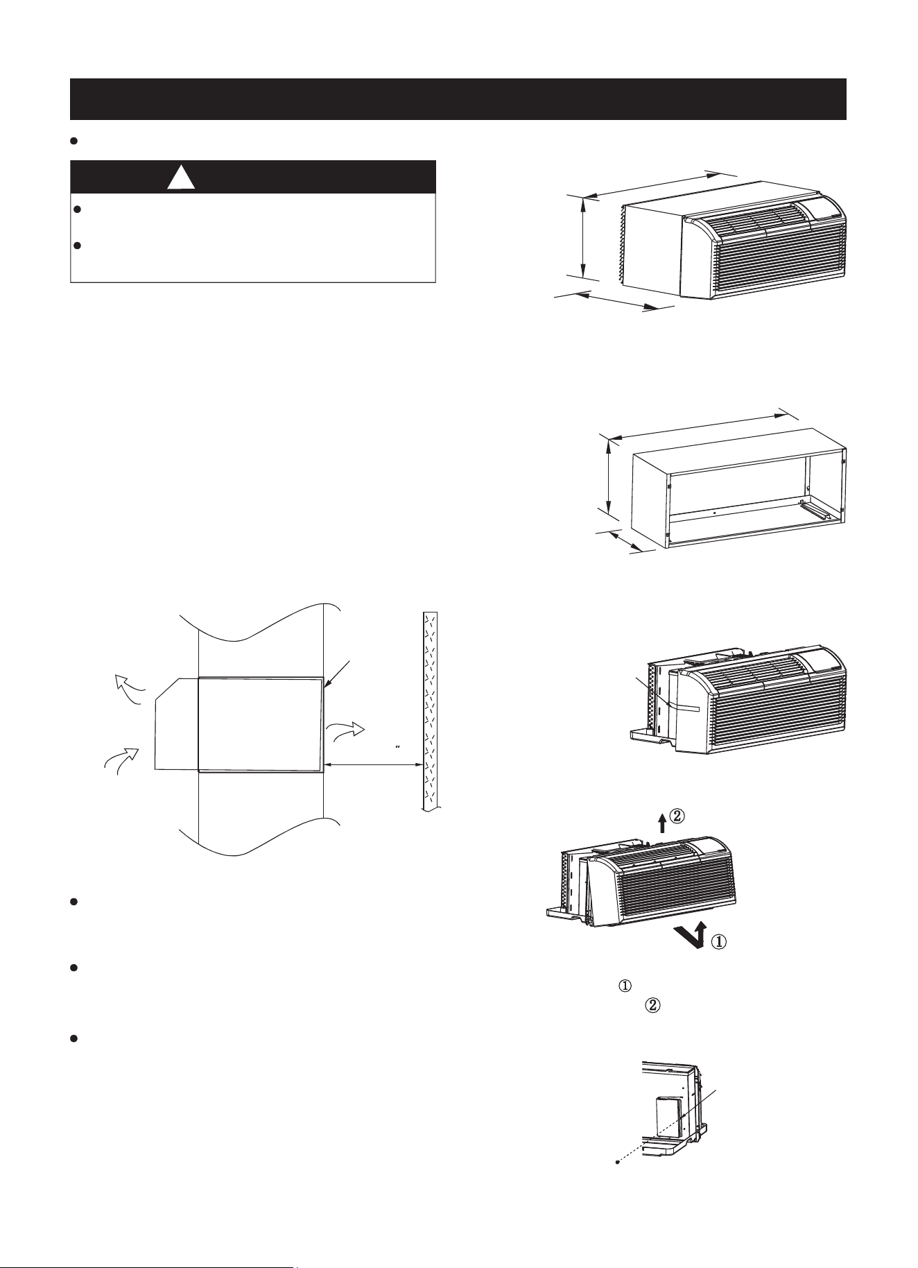
- When installing the sleeve,make certain there is
nothing within 20" of the back that would interfere
with heat radiation and exhaust air flow. (See Fig. 2.)
!
CAUTION
There are sharp edges and extreme care should
be used to avoid serious cuts.
The air conditioner is heavy. Always use 2 people
when lifting or moving unit.
COOLED
AIR
INTAKE
AIR
WALL
WALL
HEAT
RADIATION
SLEEVE
Over 20
Fig. 2
Fig. 3
Fig. 4
Fig. 5
PREPARATION OF SLEEVE ASSEMBLY (optional)
- Refer to the installation instruction of sleeve assembly
for details.
UNIT INSTALLATION
- Carefully remove shipping tape from the front panel.
(See Fig. 3)
Shipping
tape
- Remove the shipping screw from the vent door. (See
Fig. 5)
- Remove the front panel. (See Fig. 4)
Shipping
screw
1067mm/42inch
408mm/16inch
606mm/23.9inch
Fig. 1a - Dimensions of Air Conditioner
376mm/14.8inch
408mm/16inch
1067mm/42inch
Fig. 1b - Dimensions of Sleeve
Assembly (optional)
- Pull out at the bottom to release it from
the tab .
- Then lift up .
PREPARATION OF REAR GRILLE ASSEMBLY (optional)
- Refer to the installation instruction of rear grille
assembly for details.
INSTALLATION
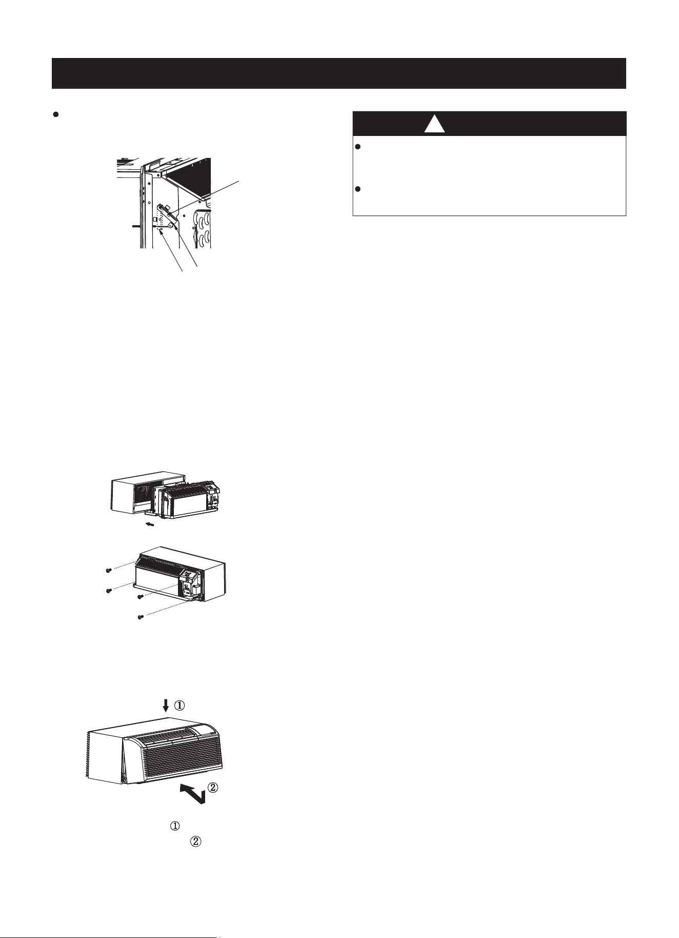
UNIT INSTALLATION (CONTINUED)
- Rotate the vent control lever to either open or close
the vent door.(See Fig. 6.)
Vent control lever
Vent open
Vent closed
Fig. 6
Fig. 7
Fig. 8
Fig. 9
- Lift unit level and slide unit into wall sleeve until
firmly against front of wall sleeve and secure with
4 screws and washers (supplied in the SLEEVE
ASSEMBLY ) through the unit flange holes.
(See Fig. 7 and Fig. 8.)
- Reinstall front panel.(See Fig. 9.)
Place tabs over top rail . Push Inward at bottom
until panel snaps into place ..
NOTE:When vent control lever set at CLOSED, only
the air inside the room is circulated and filtered.
When set at OPEN, some outdoor air will be drawn
into room. This will reduce heating or cooling efficiency.
!
CAUTION
Do not put obstacles around air-inlet or
inside of air-outlet of the unit, such as a window
curtain, etc.
Always insert the filter securely; clean filter once
every two weeks as required.
INSTALLATION (Continued)
11
FRONT PANEL AND CASE
- Turn unit off and disconnect power supply. To clean,
use water and a mild detergent. use bleach
and abrasivers. Some commercial cleaners may
damage the plastic parts.
DO NOT
Fig. 10a - Removing Air Filter
Fig. 10b - Replacing Air Filter
Fig. 11
OUTDOOR COIL
- Coil on outdoor side of unit should be checked
regularly. Unit will need to be removed to inspect
dirt build-up that will occur on the inside of the coil.
If clogged with dirt and soot, coil should be
professionally cleaned. Clean inside and outside of
outdoor coils regularly.
Never use a high-pressure spray on coil.NOTE:
AIR FILTERS
IMPORTANT: TURN UNIT OFF BEFORE
CLEANING.
- The most important thing you can do to maintain
unit efficiency is to clean the filters once every
two weeks as required.
Clogged filters reduce cooling, heating and airflow.
!
CAUTION
Failure to follow this caution may result in
equipment damage or improper operation.
operate unit without filters in place. If a filter
becomes torn or damaged, it should be replaced
immediately.
Operating without filters in place or with damaged
filter will allow dirt and dust to reach indoor coil and
reduce cooling, heating, airflow and efficiency of
unit. Airflow restriction may cause damage to unit.
Do not
UNIT DAMAGE HAZARD
-
Decrease cost of operation.
Save energy.
Prevent clogged indoor coil.
Reduce risk of premature component failure.
Keeping filters clean will:
-
Vacuum off heavy soil.
Run water through filter.
Dry thoroughly before replacing.
To Clean Air Filters:
Pull up
2 Air filters
Push down
VENT DOOR FILTER
IMPORTANT: TURN UNIT OFF BEFORE
CLEANING.
- If the vent door is open,access requires the removal
of the unit from the wall sleeve. Clean the vent filter
twice a year or as required.
- Make sure to remove the shipping screw from the
vent door. (See Fig. 5.)
- Rotate the vent control lever to open the vent door.
(See Fig. 6.)
- Remove four screws from the vent door filter.
(See Fig. 11.)
- First, pull out the vent door steel wire from the hole
of the vent door, then take off the vent door and filter.
(See Fig. 11.)
- Clean the filter. Dry thoroughly before replacing.
- Replace the vent door and filter. Reinstall the
four screws.
- Reinsert the vent door steel wire into the hole of the
vent door.
Vent door
control lever
Vent door
steel wire
Vent door
filter
Screws
Ven t door
CARE AND CLEANING
12
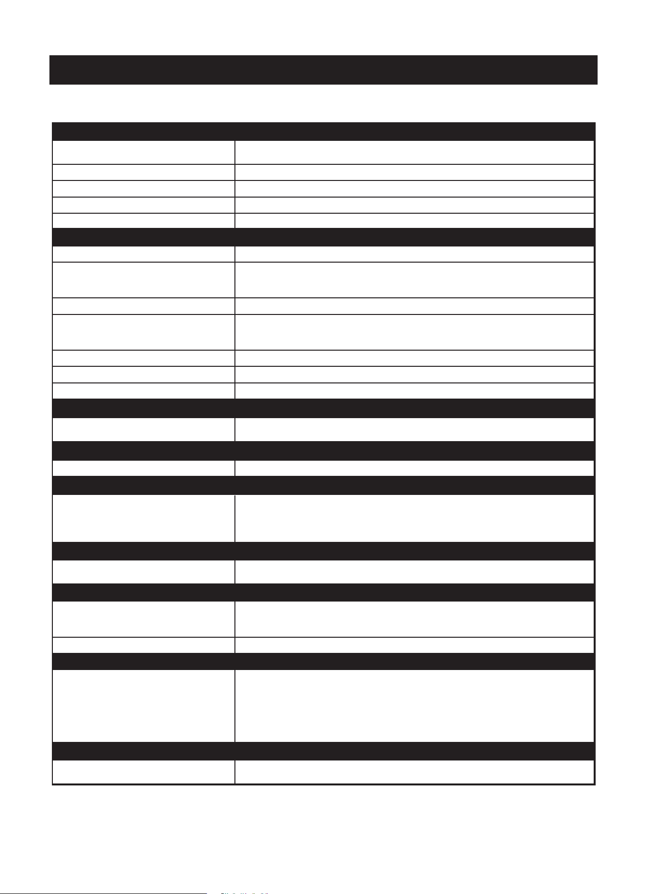
NOTES:
1.If circuit breaker is tripped or fuse is blown more than once, contact a qualified electrician.
2.If unit is installed where condensation drainage could drip in an undesirable location, an accessory drain kit should be
installed and connected to a drain system.
TROUBLESHOOTING
Before calling for service, please review the chart below.
13
POSSIBLE CAUSES SOLUTIONS
• Unit may have become unplugged.
• Check that plug is plugged securely in wall receptacle.
Note: Plug has a test/reset button on it. Make sure that the plug has not tripped.
• Fuse may have blown. • Replace the fuse. See Note 1 (below).
• Circuit breaker may have been tripped. • Reset circuit breaker. See Note 1 (below).
• Unit may be off. • Turn unit on (bottom right button on keypad).
• Unit may be in a protection mode.
• Unit air discharge section is blocked.
• Make sure curtains, blinds or furniture are not restricting or blocking unit airflow.
• Temperature setting is not high or low
enough.
• Reset to a lower or higher temperature setting.
Note: Set point limits may not allow the unit to heat or cool the room to the
temperature desired. Check section on dipswitch settings.
• Unit air filters are dirty. • Remove and clean filters
• Room is excessively hot or cold when
unit is started.
• Allow sufficient amount of time for unit to heat or cool the room. Start heating or
cooling early before outdoor temperature, cooking heat or groups of people
make room uncomfortable.
• Vent door left open. • Close vent door.
• Unit may be in a protection mode. • Check dipswitch settings for desired comfort.
• Compressor is in time delay. • Wait approximately 3 minutes for compressor to start.
• Strange numbers/characters appear
on the display.
• The unit may be in a protection mode.
• The unit may be set for °C (instead of °F).
• The unit is making noises. • Clicking, gurgling or whooshing noises are normal during operation of unit.
• Water is dripping outside.
• If a drain kit has not been installed, condensation runoff during very hot and
humid weather is normal. See Note 2 (below). If a drain kit has been installed
and is connected to a drain system, check gaskets and fittings around drain for
leaks and plugs.
• Wall sleeve is not installed level
• Wall sleeve must be installed level for proper drainage of condensation. Check
that installation is level and make any necessary adjustments.
• Low outdoor temperature
• When outdoor temperature is approximately 55°F or below, frost may form on
the indoor coil when unit is in Cooling mode. Switch unit to FAN operation until
ice or frost melts.
• Dirty filters • Remove or clean filters.
• Compressor may have cycled, so
compressor is in a restart protection.
• Random Compressor restart - Whenever the unit is plugged in or power has
been restarted, a random compressor restart will occur. After a power outage,
the compressor will restart after approximately 3 minutes.
• Compressor Protection - To prevent short cycling of the compressor, there is
a random startup delay of 3 minutes and a minimum compressor run time of 3
minutes.
• The electric heating function is not
working properly.
• The evaporator should be cleaned once every three months by a professional.
ELECTRIC HEATING FAILURE
UNIT DOES NOT START
UNIT NOT COOLING/HEATING ROOM
WATER DRIPPING INSIDE
ICE OR FROST FORMS ON INDOOR COIL
COMPRESSOR PROTECTION
DISPLAY HAS STRANGE NUMBERS/CHARACTERS ON IT
UNIT MAKING NOISES
WATER DRIPPING OUTSIDE
PA/Manual_PTACs/01152018

Specification and performance data is subject to change without notice.
Printed in China
Distributed by:
CLL ,eriA tcefreP
5401 Dansher Rd.
Countryside, IL 60525
844-472-2473
www.perfectaire.us