Loading ...
Loading ...
Loading ...
24 - INSTALLATION 91477A424/A
standard is stamped on the hose).
Carefully screw the hose connector 3 onto the
appliance’s gas connector 1 (½” thread ISO
228-1), placing the seal 2 between them. Hose
connector 4 can also be screwed to hose
connector 3, depending on the diameter of the
gas hose used.
After tightening the hose connector(s), push gas
hose 6 onto the hose connector and secure it
with the clamp 5, which must be compliant with
current regulations.
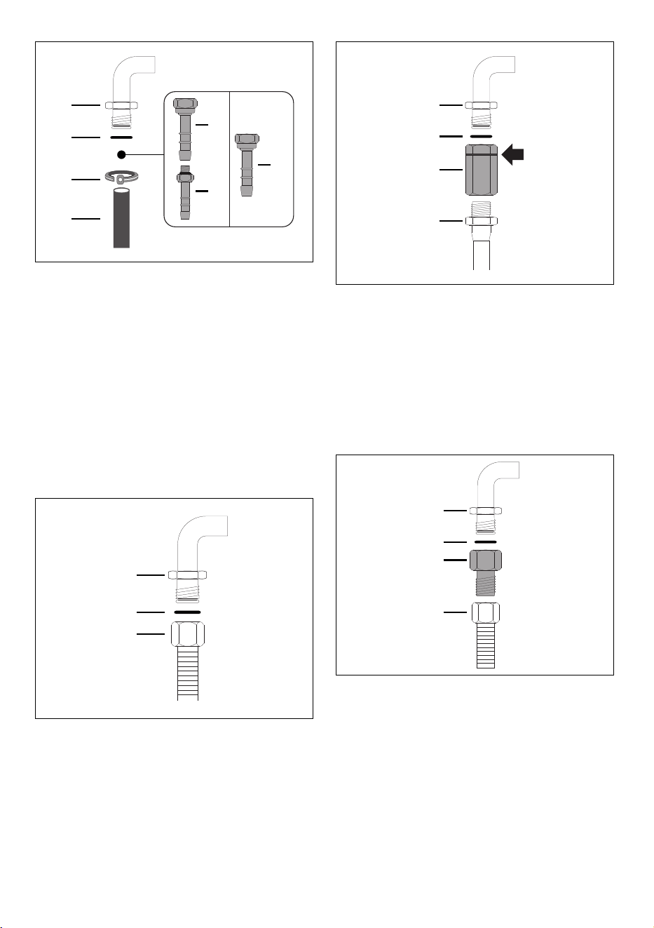
Connection with a steel hose
Make the connection to the gas mains using a
continuous wall steel hose whose specifications
comply with the applicable standard.
Carefully screw the connector 3 to the gas
connector 1 of the appliance, placing the seal 2
between them.
Connection with a steel hose with bayonet
fitting
Carry out the connection to the gas mains using
a steel hose with bayonet fitting compliant with
B.S. 669.
Apply insulating material to the thread of the gas
hose connector 4 and screw the adapter 3 onto
it. Screw the assembly onto the movable
connector 1 of the appliance, inserting the seal
provided 2 between them.
Connection with a steel hose with conical
fitting
Make the connection to the gas mains using a
continuous wall steel hose whose specifications
comply with the applicable standard.
Carefully screw the hose connector 3 to the
appliance’s gas connector 1 (½” thread ISO
228-1), placing the seal 2, provided, between
them. Apply insulating material to the thread of
connector 3 and then screw the steel hose 4
onto the connector 3.
1
2
5
6
3
3
4
2
1
3
2
1
4
3
2
1
4
3
Loading ...
Loading ...
Loading ...