MOBILE 205L DRUM HANDLER
MODEL NO: DH02.V2
Thank you for purchasing a Sealey product. Manufactured to a high standard, this product will, if used according to these
instructions, and properly maintained, give you years of trouble free performance.
IMPORTANT: PLEASE READ THESE INSTRUCTIONS CAREFULLY. NOTE THE SAFE OPERATIONAL REQUIREMENTS, WARNINGS & CAUTIONS. USE
THE PRODUCT CORRECTLY AND WITH CARE FOR THE PURPOSE FOR WHICH IT IS INTENDED. FAILURE TO DO SO MAY CAUSE DAMAGE AND/OR
PERSONAL INJURY AND WILL INVALIDATE THE WARRANTY. KEEP THESE INSTRUCTIONS SAFE FOR FUTURE USE.
1. SAFETY
9 Before use inspect the drum handler for damage and worn components.
9 If in any doubt do not use and have inspected/repaired by an authorised service agent.
9 Only use the drum handler on firm, level, unobstructed surfaces which are capable of
supporting the handler and drum.
8 DO NOT overload the drum handler - maximum capacity is 360kg.
8 DO NOT ride or allow others to ride on the drum handler.
8 DO NOT use on tarmacadam. The drum handler must only be used on a concrete surface.
9 Replace or repair damaged parts. Use only recommended parts. Unauthorised parts may be dangerous and will invalidate the warranty.
9 Use a qualified person to lubricate and maintain the drum handler.
WARNING! Failure to comply with these instructions may result in loss of load, damage to drum handler or other property and/or
personal injury.
2. INTRODUCTION
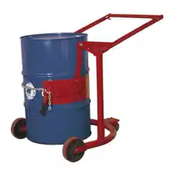
Ideal for manoeuvring, relocating and draining fully loaded drums. Lever
handle raises drum in stages with ngertip operated locks. Adjustable for
reach/leverage and clamp height. Clips on both sides hold drum secure in
vertical or horizontal positions. Drum can be manually adjusted and held at
any angle or, if contents need mixing, can be turned end-over-end. Fitted with
two smooth-rolling, heavy-duty wheels and one castor with brake. Suitable for
205L drums.
3. SPECIFICATION
Model No: .......................... DH02.V2
Drum Size: .............................205ltr
Lifting Weight:...........................360kg
FIGURE 3 REFERENCE
Item Description Item Description Item Description
1 Chassis 7 Chain 13 Adjustment Hole
2 Mast 8 Wheel 14 Pawl
3 Supporting Hoop 9 Caster 15 Hinged Hoop
4 Handle 10 Location Lever 16 Adjustment Hole
5 Location Pin 11 Lifting Arm 17 Hook
6 Fastening Lever 12 Hanger Plate
4. ASSEMBLY
4.1. Remove the sub-assemblies from packaging in following order.
A Chassis (fig.3.1).
B Mast (fig.3.2).
C Supporting Hoop (fig.3.3).
D Handle (fig.3.4).
E Washers, nuts and clamp collars.
4.2. Assemble mast (B) x 2 onto chassis (A) with the screws, washers and nuts
provided (E).
4.2.1. Bolt the handle (D) to the masts (B). See (fig.3.11).
4.2.2. Attach the hangers (fig.3.12) on the supporting hoop assembly (C) onto the
lifting arms (fig.3.11) on the handle (D) and secure with bolts provided.
4.2.3. Refer to parts diagram for additional guidance.
DH02.V2 Issue 4 (3) 25/09/2023
Original Language Version
© Jack Sealey Limited
g.3
Refer to
instructions
Wear protective
gloves
Wear safety
footwear
g.1
g.2
5. OPERATION
5.1. CLAMPING DRUM
5.1.1. The opening section of the hoop (fig.3.15) is sprung loaded to remain open when
not clamped to a drum.
5.1.2. Position the Drum Handler so that the supporting hoop (fig.3.3) encompasses the
drum to be lifted.
5.1.3. Pull the location levers (fig.3.10) to release the handle (fig.3.4) and position the
supporting hoop in the middle of the drum.
5.1.4. Release the location levers to lock the handle in this position.
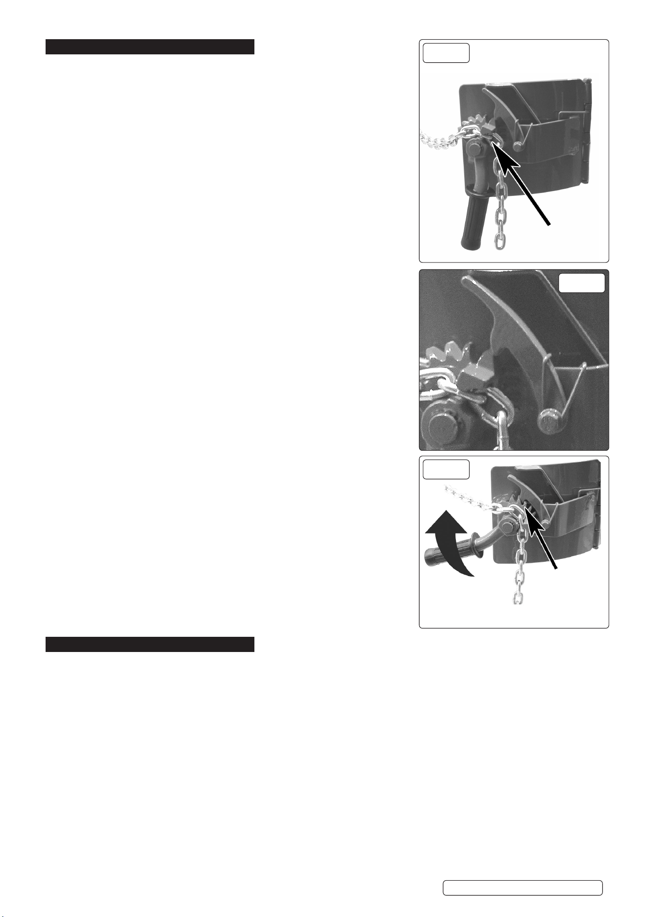
5.1.5. Turn the fastening lever (fig.3.6) so the teeth are pointing upwards, take the slack
up on the chain and place it in the groove (fig.4) on the fastening lever ensuring that
it is fully located as in (fig.4.1).
5.1.6. Pull the fastening lever sharply clockwise until the chain is tight and the ratchet pawl
has locked the ratchet as in (fig.5).
5.1.7. Check that the drum is now securely held in place. If the chain is not tight repeat
procedure 5.1.5 to 5.1.6 but take more slack out of the chain. The drum is now
ready to be lifted.
5.2. LIFTING DRUM
5.2.1. Pull the handle (fig.3.4) downwards, this will lift the drum.
5.2.2. When the drum is at the required height, slowly release the handle and the location
levers will automatically lock the handle in place.
5.3. TRANSPORTATION
5.3.1. Push or pull the drum handler using the handle to the required destination. Apply
pressure left or right to steer the handler.
WARNING! Ensure that there are no obstructions in your path, make sure the
floor surface is suitable to take the weight of the fully laden drum handler.
5.4. LOWER & RELEASE DRUM
5.4.1. To lower the drum, apply downward pressure to the handle (fig.3.4).
5.4.2. Pull the two location levers (fig.3.10) at the same time.
5.4.3. This will release the handle and drum which may now be lowered to the ground,
when the drum reaches a firm surface, release the location levers.
5.4.4. Turn the fastening lever clockwise slightly to disengage the ratchet pawl.
5.4.5. Release the fastening lever and remove the chain and hang it on the hook (fig.3.17).
5.4.6. Pull the drum handler away from the drum.
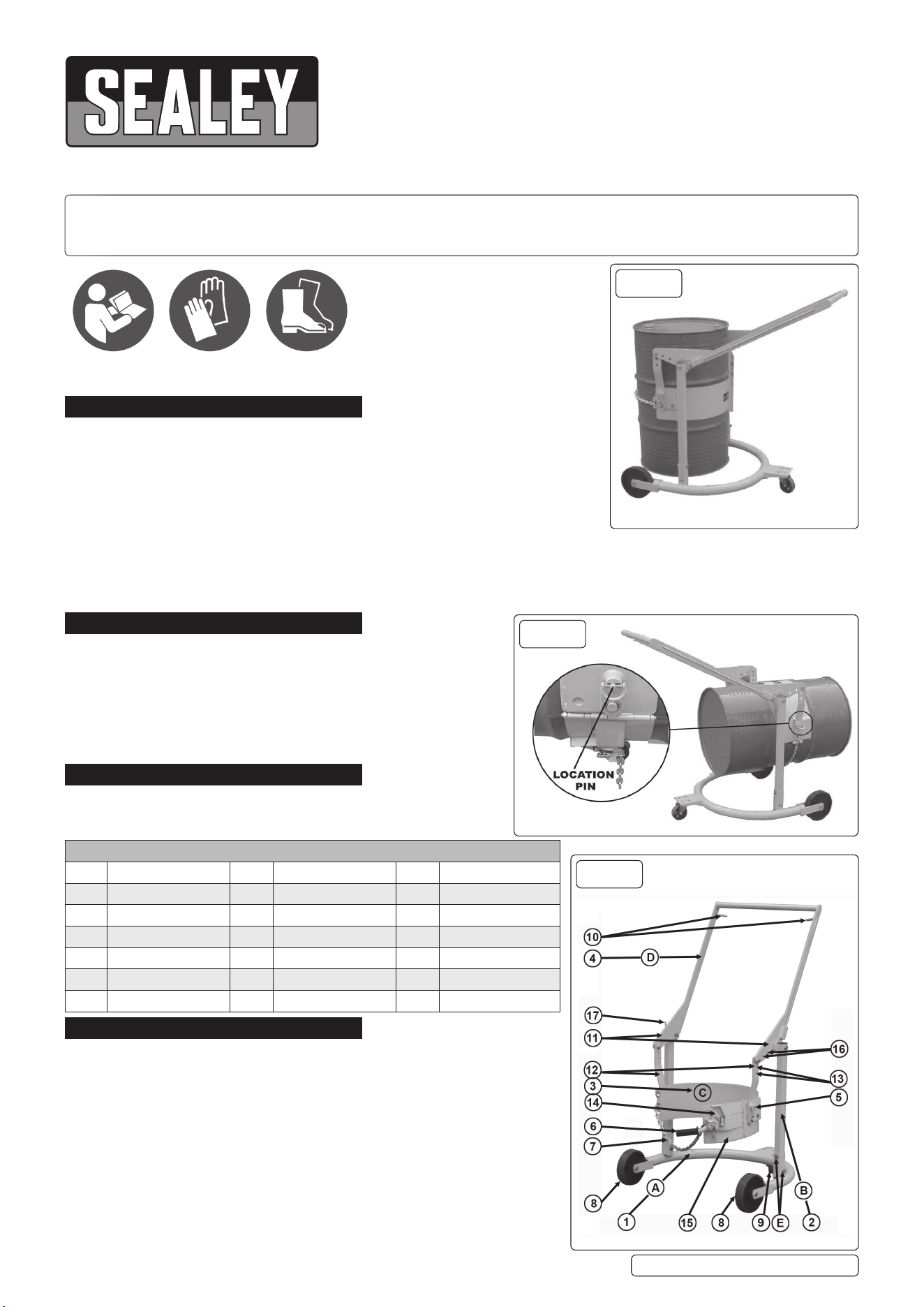
5.5. ROTATE THE DRUM
5.5.1. The drum handler can rotate the drum from vertical to horizontal position.
5.5.2. To turn the drum from vertical to horizontal disengage pins (fig.2) and turn through
90° to lock them in the disengaged position and then turn the drum through 90° to
the horizontal position.
5.5.3. Rotate the pins again until they engage with the supporting hoop to secure the drum
in the horizontal position.
NOTE: Before rotating drum make sure drum has been lifted sufficiently high
enough allowing it to turn without interference from the ground.
5.6. ADJUSTMENT
5.6.1. If the supporting hoop is too high to hold the middle of the drum while the handle is
at its highest point or the drum cannot be lifted to the required height when the handle
has reached its lowest point it will be necessary to adjust the height of the supporting
hoop.
5.6.2. Choose another hole (fig.3.13 & 16) on the lifting arm (fig.3.11) and or the hanger
plates (fig.3.12) remove the hanger plate bolts from the original position an relocate
them in the new position ensuring that the same hole is chosen for each side.
6. MAINTENANCE
6.1. Regularly check the drum handler chassis and wheels for rigidity. Ensure that the rear castor is firmly secured to the chassis.
6.2. Regularly check the pawl and ratchet for wear. Replace when necessary.
6.3. Regularly check the drum handlers connecting components such as retaining pins, nuts and washers for lubrication and/or wear.
6.4. Keep handle free from grease and oil to prevent accidents.
DH02.V2 Issue 4 (3) 25/09/2023
Original Language Version
© Jack Sealey Limited
g.4
Chain pulled
tight and
secured by
ratchet pawl
g.4.1
g.5
Locate chain in
fastening layer

Sealey Group, Kempson Way, Suffolk Business Park, Bury St Edmunds, Suffolk. IP32 7AR
01284 757500 sales@sealey.co.uk www.sealey.co.uk
Note: It is our policy to continually improve products and as such we reserve the right to alter data, specifications and component parts without prior
notice. Please note that other versions of this product are available. If you require documentation for alternative versions, please email or call
our technical team on technical@sealey.co.uk or 01284 757505.
Important: No Liability is accepted for incorrect use of this product.
Warranty: Guarantee is 12 months from purchase date, proof of which is required for any claim.
ENVIRONMENT PROTECTION
Recycle unwanted materials instead of disposing of them as waste. All tools, accessories and packaging should be sorted,
taken to a recycling centre and disposed of in a manner which is compatible with the environment. When the product
becomes completely unserviceable and requires disposal, drain any fluids (if applicable) into approved containers and
dispose of the product and fluids according to local regulations.
REGISTER YOUR
PURCHASE HERE
© Jack Sealey Limited
Original Language Version
DH02.V2 Issue 4 (3) 25/09/2023
