
• Do not use an extension cord or adapter plug with this appliance.
• The water heaters must be electrically grounded in accordance with local codes and
ordinances or, in the absence of local codes, in accordance with the National Electrical Code,
ANSI/NFPA No. 70.
• Turn off the electrical power supply by unplugging the power cord or by turning off the electricity at the circuit
breaker. (The temperature controller does not control the electrical power.)
• Turn off the gas at the manual gas valve, usually located immediately below the water heater.
• Turn off the incoming water supply. This can be done at the isolation valve immediately below the water heater
or by turning off the water supply to the building.
Applicable Product Rinnai Tankless Rack System (TRS) (Outdoor Electrical Installations)
Applicable Models TRS03CXiN, TRS03ILCXiN, TRS04CXiN, TRS05CXiN, TRS06CXiN
Overview
This document provides instructions on how to connect electrical power on outdoor TRS installations. Refer to the TRS
Installation Manual (supplied with the TRS) for all other installation information.
The electrical assembly (Figure 1) installed on the TRS is rated for indoor use only. When installing a TRS outdoor, the
power cables on the CX199iN tankless water heaters should be replaced with hardwire leads, and the electrical supply
connections should be made as shown in these instructions.
Leave the electrical assembly on
the TRS, but DO NOT use it for
outdoor installations.
Tools / Materials Required
The 4-Unit and 6-Unit Electrical Assemblies are for Indoor Use Only
Supplied with TRS:
• Hardwire adapter (part number: 105002077) (Figure 2)
Field-Supplied:
• Phillips head screwdriver
• Wire
• Conduit
• Disconnect Switch
This Document Applies to Outdoor TRS Installations Only
and is a Supplement to the TRS Installation Manual
To protect yourself from harm, follow the steps below before proceeding:
Hardwire Adapter
Figure 2
Figure 1
TRS Outdoor Electrical Supplements Instructions 2 of 3
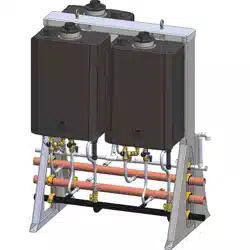
6. Use a screwdriver to remove the screw from the bottom of the water heater cabinet to free the
power cable. Completely remove the cable. The screw and power cable will not be used again and
can be discarded.
Screw
Power Cable
REMOVE GROUND WIRE AND POWER CABLE:
Instructions
1. Turn off and disconnect 120 V power supply, water supply, and gas supply.
2. Remove the water heater front panel (refer to the Tankless Water Heater Installation and Operation
Manual for detailed instructions).
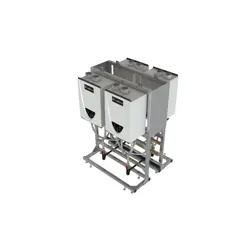
3. Move up controller and pull bottom of controller toward you. Remove controller from its location and
let is rest next to the water heater.
4. Locate the power supply connection on the PC board located behind the controller.
Controller
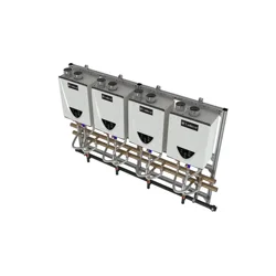
PC Board
Power Supply
Connection
5. Disconnect the molex connection, and then remove the ground wire from the grounding tab.
Molex
Connection
Ground Wire
Figure 6
Figure 5
Figure 4
Figure 3
TRS Outdoor Electrical Supplements Instructions 3 of 3
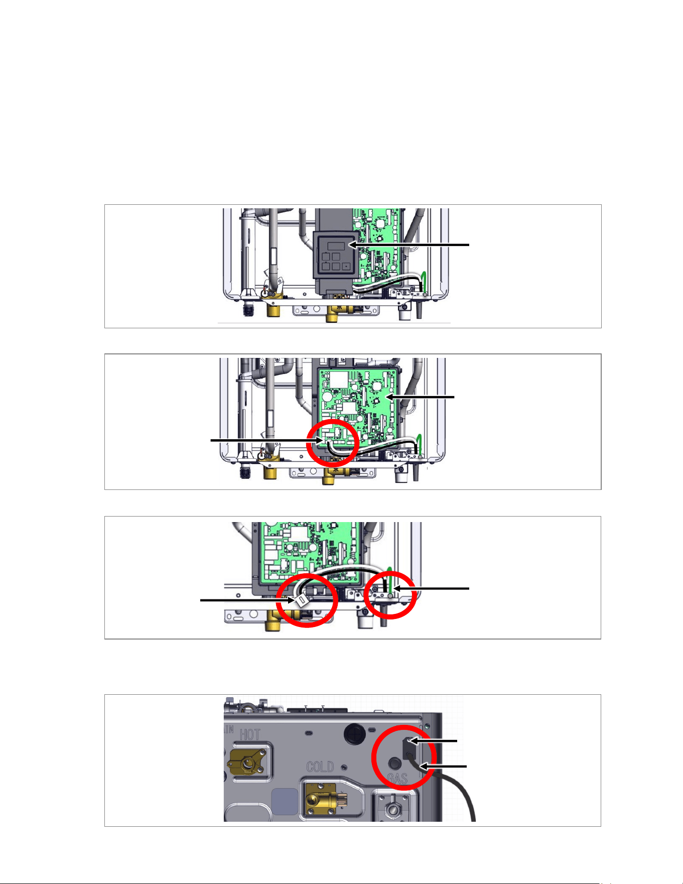
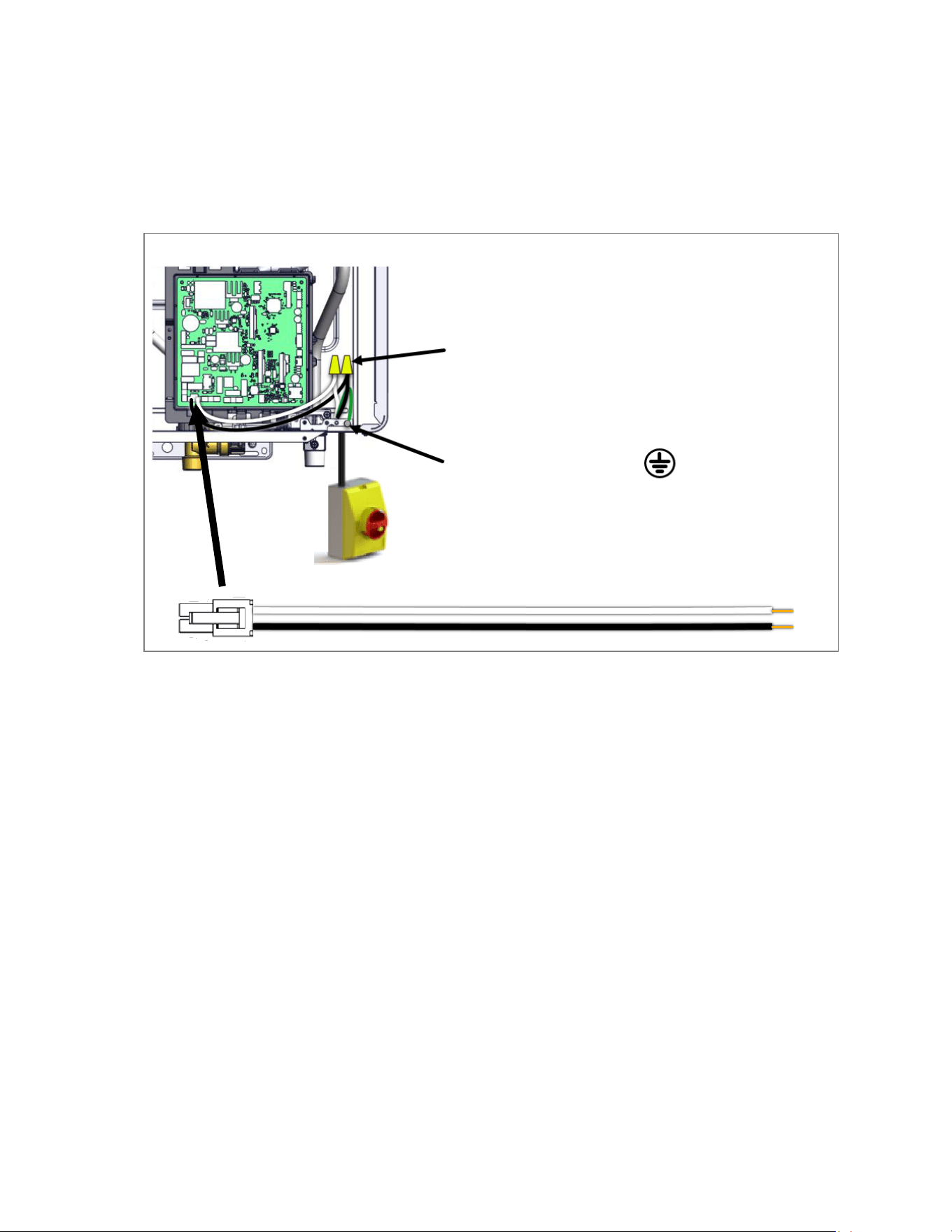
7. Plug the hardwire adapter (supplied with TRS) into the PC board, and run the wires behind the tabs
to the right-hand side of the cabinet, where the grommets are located. The other end of the hardwire
adapter will connect to the building power supply.
When connecting the power supply, follow these guidelines:
• Do not rely on the gas or water piping to ground the water heaters. Ground locations are
provided inside each water heater.
• The water heaters requires 120 VAC, 60 Hz power from a properly grounded circuit.
• On external (outdoor) models, a disconnect switch must be provided and installed for the
incoming 120 VAC power. The switch should be a type that is suitable for outdoor use. Check
the National Electrical Code, ANSI/NFPA 70 and your local codes for a proper switch type to
use in your area. Power connections must be protected from the weather and flexible cords
must use an appropriate strain relief.
• The wiring diagram is located on the inside of the water heater front cover.
100000893
4/2024
CONNECT THE POWER SUPPLY:
Hardwire Adapter
8. Re-install controller.
Refer to the TRS Installation Manual for all other installation steps. When system installation is
complete, remember to:
• Install water heater front panel.
• Connect gas and water supply.
• Connect and turn on 120 V power supply.
Figure 7
120V Wiring
• White Wire (Neutral)
• Black Wire (Hot Leg)
Disconnect switch (required on external installations)
Ground connection screw