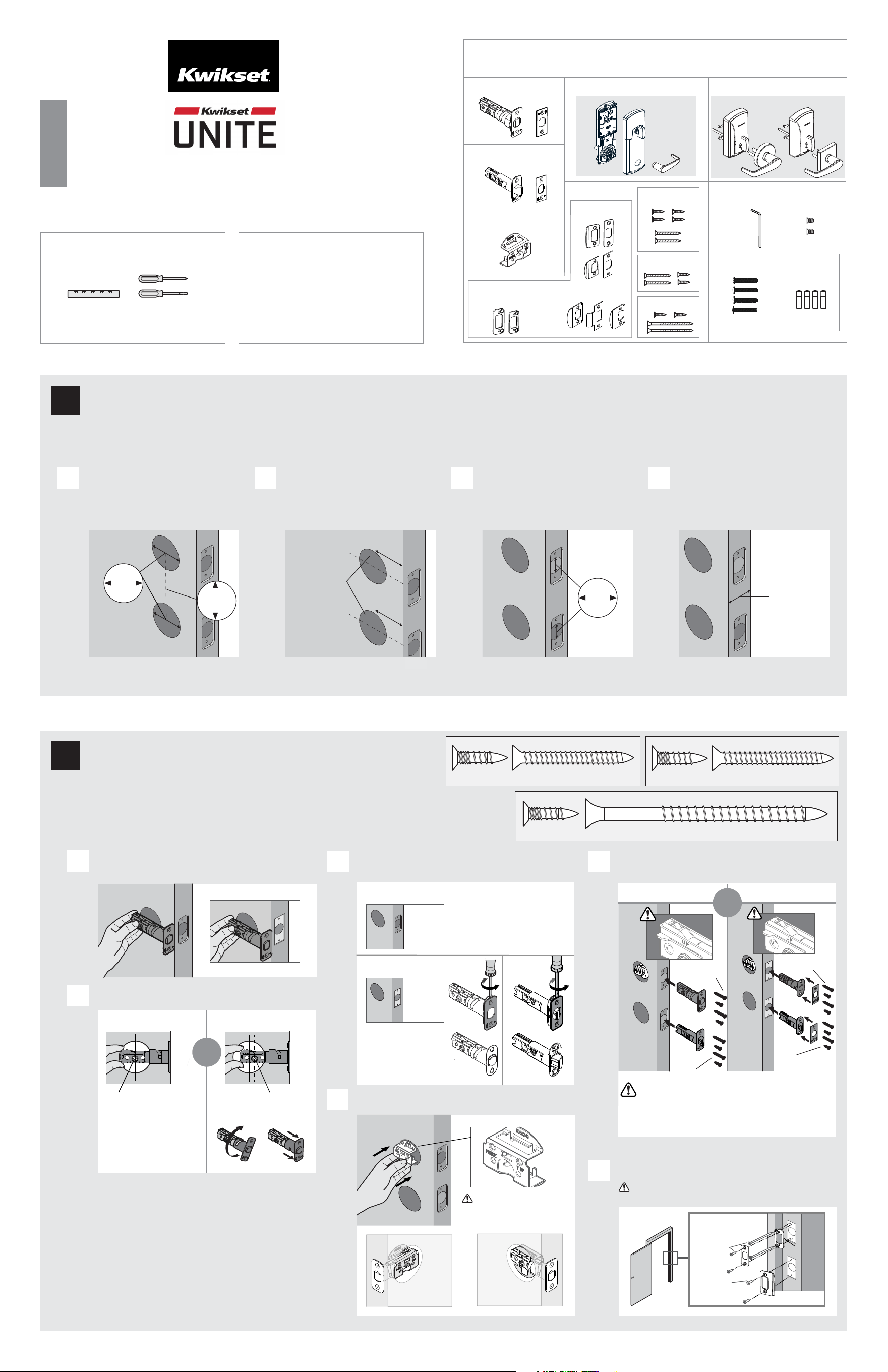
If drilling a new door, use the supplied template and the complete
door drilling instructions available at www.kwikset.com/doorprep.
backset
Measure to conrm the holes in the door
are 2-1/8 in (54 mm) and they measure
center to center 4 in or 5-1/2 in
(102 or 140 mm).
Measure to conrm that the backsets
are either 2-3/8 or 2-3/4 in (60 or 70 mm).
2-3/8 or 2-3/4 in
60 or 70 mm
35 – 51 mm
1-3/8 – 2 in
Measure to conrm that the holes in
the door edge are 1 in (25 mm).
Measure to conrm that the door is
between 1-3/8 and 2 in (35 mm and
51 mm) thick.
A
C E
B C D
Which latch face are you installing?
2-1/8 in
54 mm
door frame
F
Install strike on the door frame.
Make sure the hole in the door frame is drilled a
minimum of 1 in (25 mm) deep.
1
Prepare the door and check dimensions
2
Install the latches and strikes
1 / 4
ENGLISH
Installation and User Guide
Required tools
Kwikset
Technical Support
www.kwikset.com
actual size
03809
For Latch /
Strike Bag
(2x)
(2x)
Latch Bolt
Deadbolt
Strike
Exterior Assembly
Shield
Parts in the box
For Latch / Strike For Lock
Interior Assembly
Traditional Contemporary
52469
53082
52301
52300
1-800-327-5625
52303-001
Rev 01
actual size
52469
(4x)
(2x)
03809
52469 (2x)
(For Latch/
Strike Bag
)
(2x)
53082
(2x)
actual size
Longer screws install
closest to the door
jamb.
03809
(2x)
*Use longer screws if holes are worn out. You will
have 4 extra screws, 2 from each latch installation.
or
or
or
or
52469
(2x)
Hex
Wrench
102
or
140
mm
4
or
5-1/2
in
Reinforcement
Plate
Is the door edge chiseled with round or square corners?
Round Corner
Remove round face
with a at head
screwdriver and use
square face in step E.
Square Corner
03809
(2x)
or
or
or
or
52469
(2x)
Round Corner
or
Square Corner
Ruler Phillips and at head
screwdriver
1100 SERIES INTERCONNECT SMART LOCK
53082 (4x)
UP is on top.
UP is on top.
A
B
Is the rectangular shaped hole centered in the door hole?
YES NO
No adjustment is required.
Proceed to next step.
Rotate latch face as
shown to extend latch.
or
Hold the latch in front of the door hole, with the latch
face ush against the door edge.
D
Insert shield in the top interior door hole.
Make sure ARROW is pointing up
and the word "INSIDE" is facing
the interior of the door.
reinforcement
plate
Batteries
Plain Latch Strike
When installing the latch bolt make sure the latch bolt is
placed into the edge bore hole and through the shield
that was placed in the top interior door hole in step 2D.
latch bolt
plain latch
Plain Latch
1 in
25 mm
No further prep needed.
interior view
(latch bolt installed)
exterior view
(latch bolt installed)
2-1/8 in
54 mm
2 / 4
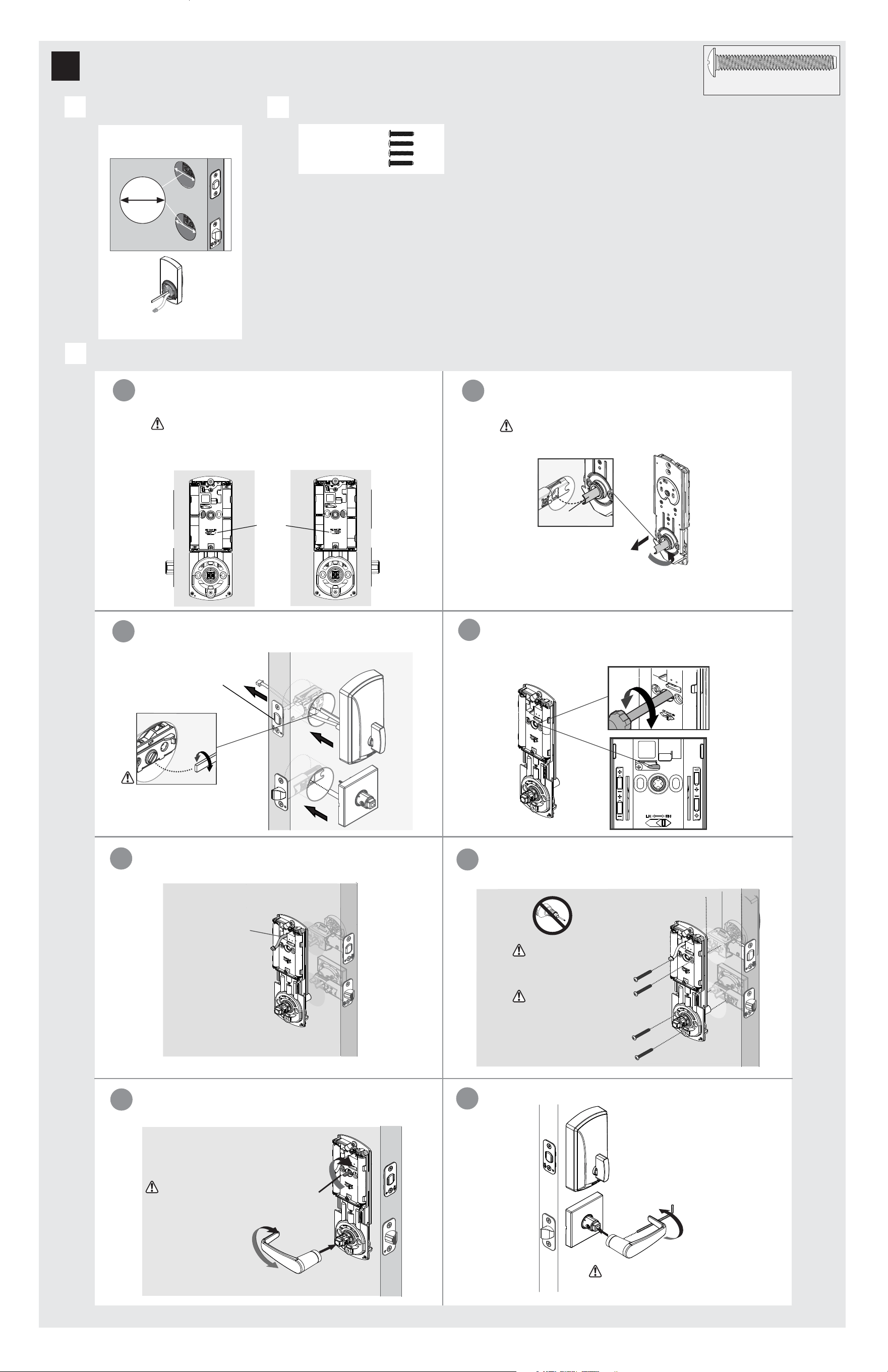
Make sure adapter ring is on exterior
assembly.
Locate screws for step 3C(f) and keep
them within reach.
Install exterior assembly and interior chassis.
A
B
C
Diameter is 2-1/8 in
(54 mm)
Adapter ring is required
for installation.
3
Install the exterior assembly
52301
actual size
(4x)
For Lock
Bag
52301
(4x)
(For Lock Bag)
b
a
d
c
f
Route cable
through the
hole above the
upper cam.
52301 (4x)
(For Lock Bag)
Tighten screws
evenly. DO NOT
over tighten screws.
Keep parallel to
edge of door.
g
h
Use the handing switch to change handing from left to
right as needed.
Ensure the curve on the spindle matches the curve on the
plain latch as shown below.
Flip interior chassis over. To change the handing of the spindle,
pull out and then rotate.
Make sure
bolt is
RETRACTED
Install exterior assembly. Route cable underneath the latch
bolt and through the shield.
Install interior chassis
Install the exterior handle.
Use hex wrench to
install exterior lever.
Rotate lever to test if the plain latch
extends and retracts smoothly. If not
adjust mounting screws.
Use the blade to extend the bolt, then place the interior
lever on chassis and rotate lever and both bolts should
retract smoothly.
If latch bolt does not extend
or retract smoothly, adjust
mounting screws.
blade
You may need to rotate
the blade to match the
orientation of the slot on
the latch.
e
Before installing interior chassis, you will need to use a screwdriver
to rotate the upper cam vertically as shown below to make
mounting screw holes visible.
Support exterior
assembly while
installing interior
chassis.
Make sure the at blade is centered in the upper cam, and the
spindle is engaged with the latch.
Before installing interior chassis, check for accurate handing. To
determine door handing, make sure the handing switch is on the
same side as the latches.
Handing
Switch
Left handing
Right handing
door door
spindle
3 / 4
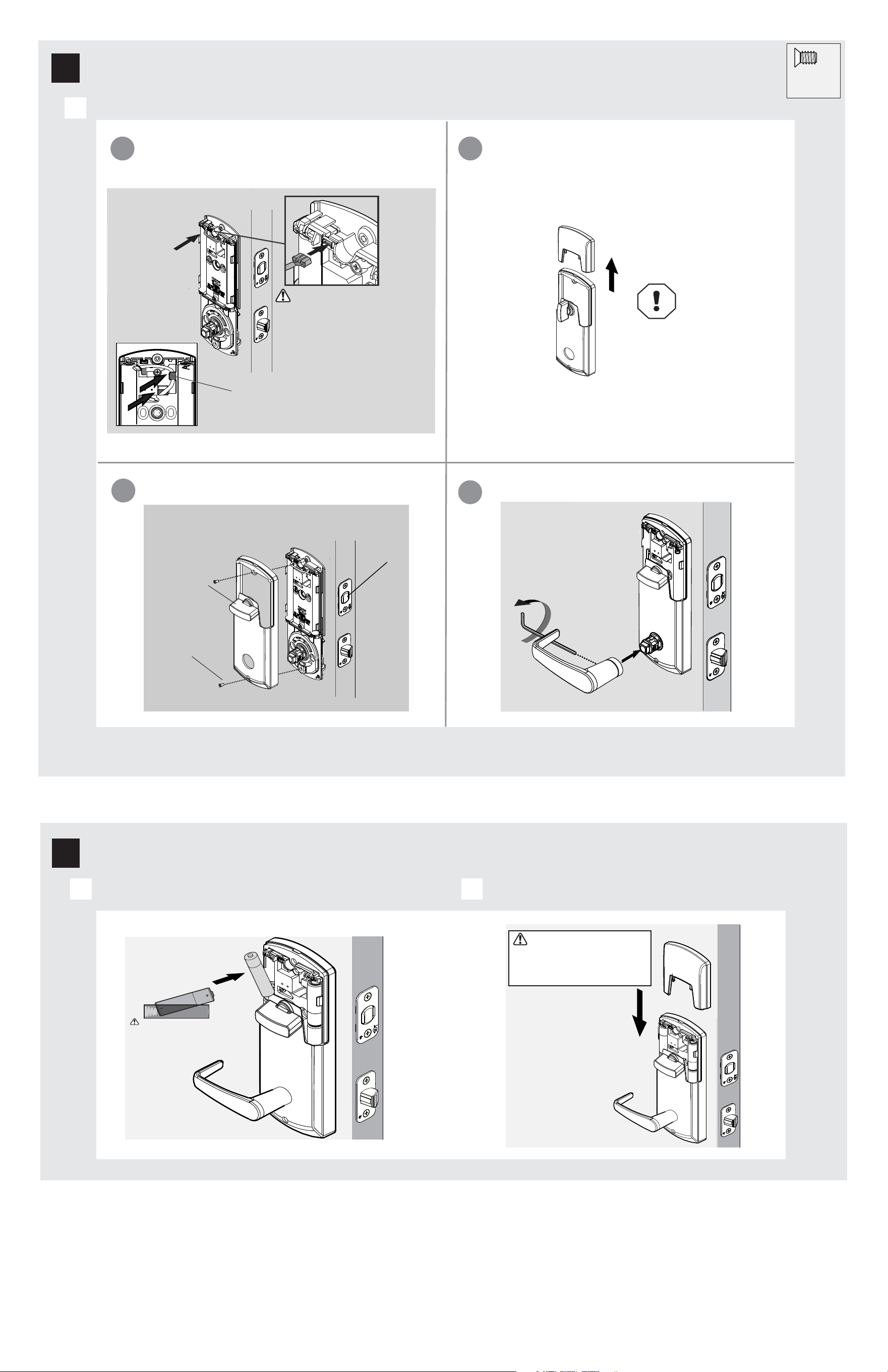
Install 4 AA batteries in interior assembly
A
5
Install the batteries
Install interior cover onto interior chassis.
A
4
Install the interior cover
For Lock
Bag
Ensure the interior battery
cover is o to install
batteries.
B
Install battery cover to the interior cover.
52300
actual size
(2x)
a
Connect cable wire as shown. Ensure a tight cable
connection.
b
Remove the battery cover from the interior cover.
Do not install
batteries until step 5.
c
Install the interior cover.
52300 (2x)
(For Lock Bag)
d
Install the interior handle.
Use hex wrench
to install interior
handle.
Make sure the
turnpiece is
horizontal
as shown.
Ensure the red color on the
connector is on the top and
connects to the red color on
the interior assembly.
Once interior turnpiece is rotated
back to the horizontal position, the
exterior turnpiece will be enabled or
active for 5 seconds. Door MUST remain
open to avoid accidental lockout.
Any excess wire can be pushed under the
tab above the hole.
Ensure correct polarity.
For best results, use new,
non-rechargeable
alkaline batteries only.
Make sure
bolt is
RETRACTED
© 2023 ASSA ABLOY
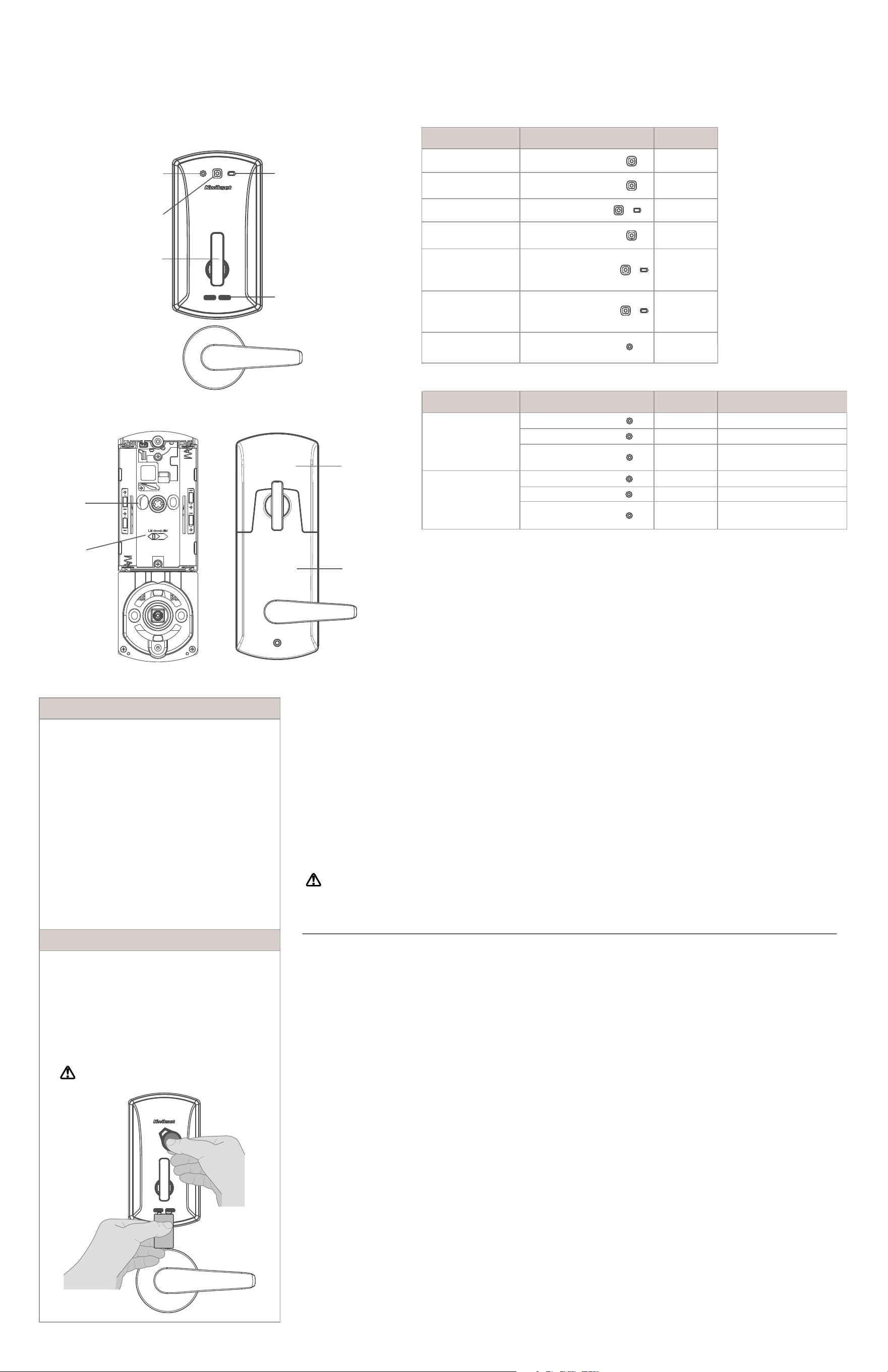
Exterior
Interior
Unite at a Glance
Upper
cam
Handing
switch
Interior
Cover
Reference Guide
4 / 4
Important Safeguards
1. Read all instructions in their entirety.
2. Familiarize yourself with all warning and
caution statements.
3. Remind all family members of
safety precautions.
4. Always have access to your lock’s
credentials.
5.
6.
Familiarize yourself with all status LED lights
notifications.
7.
Replace low batteries immediately.
Dispose of used batteries according to local
laws and regulations.
WARNING: This Manufacturer advises that no lock can provide complete security by itself. This lock may be defeated by
forcible or technical means, or evaded by entry elsewhere on the property. No lock can substitute for caution, awareness of
your environment, and common sense. Builder’s hardware is available in multiple performance grades to suit the application. In
order to enhance security and reduce risk, you should consult a qualified locksmith or other security professional.
LightsOperation
Flashes GREEN 5xAccess Granted
Solid GREEN 3s
Power on -
Full Battery Life
Status Solid GREEN
and battery LED light
AMBER 3s
Flashes RED 3xAccess Denied
Flashes RED 5xLow battery
Power on -
Low Battery Life
Lock identication
Enrollment
System Alerts
Power on -
Moderate Battery Life
Flashes BLUE
Solid GREEN 3s
Flashes RED 3x
BLE pairing start
Pairing complete
BLE pairing/
fail or timeout
Firmware Upgrade
Flashes BLUE
Solid GREEN 3s
Flashes RED 3x
Update start
Update complete
Update pairing/
fail or timeout
Solid BLUE 3s
Programming your Lock
Lights ActionOperation
Status Solid GREEN
and battery LED light
RED 3s
Turnpiece
9V terminals
Battery
LED light
Programming
LED light
Status
LED light
Battery
Cover
Beep
Beep
1 Beep
3 Beeps
5 Beeps
1 Long Beep
1 Long Beep
1 Long Beep
then 5
Short Beeps
1 Long Beep
1 Long Beep
3 Beeps
1 Long Beep
3 Beeps
If the 4 AA batteries are too low to operate the lock,
use a 9-Volt alkaline battery to temporarily power
the lock.
Make sure both terminals on the 9-Volt battery touch
the terminals below the turnpiece. Hold the 9-Volt in
place while holding the credential on the exterior of
the lock. Hold the 9-Volt battery as well as the
credential until the lock illuminates and unlocks.
Manual Factory reset
1.
2.
3.
4.
Insert battery to power up the lock.
Status LED light displays GREEN 3s.
Rotate the interior turnpiece back and forth to extend
and retract bolt 3x within 5s.
Wait for programing LED light to alternate BLUE
and RED continuously.
Within 10s, rotate the interior turnpiece back and
forth 3x.
5.
6.
Program LED light will display solid GREEN for a
successful manual factory reset.
Fail/ Time out all LED lights will remain o.
Low Battery
WARNING: Change batteries immediately
otherwise the lock will remain unlocked.
Regulatory Compliance
FCC ID: NUL-UNT1
IC: 3022A-UNT1
-
-
This product complies with
standards established by the
following regulatory bodies:
Federal Communications
Commission (FCC)
• Industry Canada
FCC
This device's wireless operation
is safe and complies with RF
Exposure requirements. This
device complies with Part 15 of
the FCC Rules. Operation is
subject to the following two
conditions: ( 1 ) this device may
not cause harmful interference,
and ( 2 ) this device must accept
any interference received,
including interference that may
cause undesired operation. This
equipment has been tested and
found to comply with the limits
for a Class B digital device,
pursuant to Part 15 of the FCC
Rules. These limits are designed
to provide reasonable
protection against harmful
interference in a residential
installation. This equipment
generates, uses, and can radiate
radio frequency energy and, if
not installed and used in
accordance with the instructions,
may cause harmful interference
to radio communications.
However, there is no guarantee
that interference will not occur
in a particular installation. If this
equipment does cause harmful
interference to radio or television
reception, which can be
determined by turning the
equiptment o and on, the user
is encouraged to try to correct the
interference by one or more of the
following measures:
• Reorient or relocate the receiving
antenna.
• Increase the separation between
the equipment and receiver.
IMPORTANT! Changes or
modications not expressly
approved by the manufacturer
could void the user’s authority
to operate the equiptment.
Industry Canada
This device complies with
Industry Canada licence-
exempt RSS standard(s).
Operation is subject to the
following two conditions:
( 1 ) this device may not cause
interference, and ( 2 ) this device
must accept any interference,
including interference that may
cause undesired operation of the
device.
•
•
Connect the equiptment
into an outlet on a circuit
dierent from that to which
the receiver is connected.
• Consult the dealer or an
experienced radio/TV
technician for help.