Loading ...
C. Modos Brisa natural y Brisa para dormir
Presione
= Brisa natural, Brisa para dormir
El modo Brisa natura
recorrerá al azar todas las
configuraciones de velocidad.
El modo Brisa para dormir
recorrerá en orden
todas las configuraciones de velocidad.
D. Control de temporizador
Presione
= apagado automático en 1, 2, 4, 8
horas
NOTA: Su ventilador le ofrece luces indicadoras de LED.
Cuando se activa una función específica en su ventilador,
se iluminará la luz indicadora de LED correspondiente de
la función que se ha activado.
LIMPIEZA / MANTENIMIENTO
INSTRUCCIONES
Para cuidar el Ventilador de Torre en forma correcta y
segura, siga estas instrucciones cuidadosamente.
Recuerde:
FUSIBLE REEMPLAZABLE
Si el fusible de repuesto (5 amperios, 125 voltios) se daña,
visite nuestro sitio web en www.holmesproducts.com para
obtener información sobre cómo ordenar un nuevo fusible.
Siga las siguientes instrucciones para reemplazar el
fusible en la clavija.
Instrucciones de Mantenimiento para el
Usuario
1. Desconecte el ventilador. Sujete el enchufe y retírelo
del receptáculo o cualquier otro dispositivo de toma
eléctrica. Nunca desconecte jalando el cable.
2. Abra la cobertura del fusible, ubicada en la parte
superior del enchufe, utilizando su pulgar o un
destornillador plano para deslizar la cubierta hacia
abajo en dirección de las puntas.
Nota: asegúrese que la cubierta del fusible esté
completamente abierta antes de intentar retirar el
fusible.
3. Retire el fusible con cuidado utilizando un
destornillador pequeño para hacer palanca en los
extremos metálicos del fusible y sacarlo del
compartimiento (ver Fig. 6).
4. Coloque el enchufe en una superficie plana y sólida.
Inserte un fusible nuevo de 5 amperios y 125 voltios
en el compartimiento del fusible y utilice un
destornillador para asegurar los extremos metálicos
del fusible en el compartimiento.
Advertencia: riesgo de fuego. Reemplace el fusible
con otro de 5 amperios y 125 voltios solamente.
5. Deslice la cubierta del fusible de nuevo hasta cerrarla
completamente. Si se presenta alguna dificultad al
cerrar la cubierta, asegúrese de que el fusible esté
puesto en su lugar correctamente, haciendo presión
en los extremos metálicos del fusible.
6. Peligro de incendio. No reemplace el enchufe de
conexión. Cuenta con un dispositivo de seguridad
(fusible) que no debería quitarse. Deseche el
producto si el enchufe de conexión está dañado.
PLEASE READ AND SAVE THESE
IMPORTANT SAFETY INSTRUCTIONS
FEATURES - OPERATIONS
OPERATING INSTRUCTIONS (SEE FIG. 5)
Plug the fan into any standard 120 volt AC outlet. All
major features of this fan can be operated by pressing
the buttons on the control panel.
A. Power/Speed Settings
Press
= , 3, 2, 1, Off
B. Oscillation Control
Press
= Oscillation On, Off
C. Natural Breeze, Sleep Breeze Modes
Press
= Natural Breeze, Sleep Breeze
Natural Breeze Mode
will cycle through the fan
speed settings randomly.
Sleep Breeze Mode
will cycle through the fan
speed settings in order.
D. Timer Control
Press
= Turns Off in 1, 2, 4, 8 hours
NOTE: Your fan features LED indicator lights. When a
specific feature is activated on your fan, a corresponding
LED indicator light will illuminate showing which features
have been activated.
CLEANING/MAINTENANCE
INSTRUCTIONS
Follow these instructions to correctly and safely care for
your Tower Fan. Please remember:
REPLACEABLE FUSE
If your (5 Amp, 125 Volt) replaceable fuse blows, please
visit our website at www.holmesproducts.com for
information on how to order a new fuse. Follow the below
instructions to replace the fuse on the plug.
User Servicing Instructions
1. Unplug your fan. Grasp plug and remove from the
receptacle or other outlet device. Do not unplug by
pulling on cord.
2. Open fuse cover, located on the top of the plug, by
using your thumb or a flathead screwdriver to slide
the cover down towards the prongs.
Note: Ensure that fuse cover is completely open
before attempting to remove fuse.
3. Remove fuse carefully by using a small screwdriver
to pry the fuse out of the compartment by the metal
ends of the fuse (see Fig. 6).
4. Place plug on a solid, flat surface. Insert new 5 Amp,
125 Volt fuse into fuse compartment and use a small
screwdriver to secure the metal ends of the fuse into
the compartment.
Caution: Risk of fire. Replace fuse only with 5 Amp,
125 Volt fuse.
5. Slide fuse cover closed completely. If fuse cover is
difficult to close, make sure fuse is secured in place
completely by pressing down on metal ends of the
fuse.
6. Risk of fire. Do not replace attachment plug. Contains
a safety device (fuse) that should not be removed.
Discard product if the attachment plug is damaged.
ASSEMBLY INSTRUCTIONS
Assembly Time: 10-15 minutes.
Tools Required: Phillips head screw driver.
NOTE: MAKE SURE YOU REMOVE ALL CONTENTS FROM
THE PACKAGE. PLEASE CHECK PACKAGING MATERIALS FOR
PARTS THAT COULD BE REQUIRED TO OPERATE YOUR FAN.
LOCATE THE BELOW PARTS FROM THE BOX TO PREPARE
FOR ASSEMBLY:
• Fan housing
• 2 base halves
• 4 M4x12mm screws for base assembly
Follow the steps below in order to assemble the fan base
before operating your fan:
1. Pull the power cord through the center hole of the
base halves. Snap the 2 base halves together by
sliding the posts of one base half into the slots of the
second base half. (Fig. 1).
2. Align the arrow markings, located at the center hole
of the base, with arrow markings at the bottom of
the fan housing. Insert the rectangular alignment
post from the fan housing into the rectangular
alignment hole on base for proper alignment. Apply
the SAME for the circular alignment post from fan
housing and insert into the circular alignment hole on
base (Fig.2).
3. Use 4 screws (M4x12mm) provided to attach the
assembled base to the fan housing. Secure the screws
with a screwdriver (Fig. 3).
4. Wind the power cord underneath the base and snap
the cord through the cord clip (Fig. 4).
5. Turn fan right side up and place on a dry and level
surface before operating.
When using electrical appliances, basic safety precautions
should always be taken including the following:
1. Read all instructions before using this appliance.
2. Use fan only for purposes described in the instruction
manual.
3. To protect against electrical shock do not immerse
unit, plug or cord in water or spray with liquids and
plug the appliance directly into a 120V AC electrical
outlet.
4. Close supervision is necessary when any appliance is
used by or near children.
5. Unplug from outlet when not in use, when moving
fan from one location to another, before putting on
or taking off parts and before cleaning.
6. Avoid contact with moving parts.
7. Do not operate in the presence of explosive and/or
flammable fumes.
8. To avoid fire hazard, NEVER place the cord under
rugs or any parts near an open flame, cooking or
other heating appliance.
9. Do not operate any appliance with a damaged cord
or plug after the appliance malfunctions, or has been
dropped/damaged in any manner. Discard fan or
return to an authorized service facility for
examination and/or repair.
10. Do not run cord under carpeting. Do not cover cord
with throw rugs, runner, or similar coverings. Do not
route cord under furniture or appliances. Arrange
cord away from traffic area and where it will not be
tripped over.
11. The use of attachments not recommended or sold by
the appliance manufacturer may cause hazards.
12. Do not let the cord hang over the edge of a table,
counter or come in contact with hot surfaces or leave
exposed to high traffic areas.
13. Do not use outdoors.
14. To disconnect, grip plug and pull from wall outlet.
Never yank on cord.
15. Always use on a dry, level surface.
16. Do not operate fan until fully assembled with all
parts properly in place.
17. This product is intended for household use ONLY and
not for commercial or industrial applications.
18. WARNING: To reduce the risk of electrical shock
and injury to persons, do not use in window.
19. WARNING: To reduce the risk of fire or electric
shock, do not use this fan with any solid-state speed
control device.
20. This product employs overload protection (fuse). A
blown fuse indicates an overload or short-circuit
situation. If the fuse blows, unplug the product from
the outlet. Replace the fuse as per the user servicing
instructions (follow product marking for proper fuse
rating) and check the product. If the replacement
fuse blows, a short circuit may be present and the
product should be discarded or returned to an
authorized service facility for examination and/or
repair.
PLEASE READ AND SAVE
THESE IMPORTANT
SAFETY INSTRUCTIONS
CLEANING/MAINTENANCE
LEA Y CONSERVE ESTAS IMPORTANTES
INSTRUCCIONES DE SEGURIDAD
CARACTERISTICA - FUNCIONAMIENTO
INSTRUCCIONES DE ENSAMBLADO
Tiempo de ensamblado: De 10 a 15 minutos.
Herramientas requeridas. Destornillador de estrella
NOTA: ASEGÚRESE DE EXTRAER TODO EL CONTENIDO
DEL EMBALAJE. COMPRUEBE QUE EN EMBALAJE ESTÁN
TODAS LAS PIEZAS NECESARIAS PARA QUE SU VENTILADOR
FUNCIONE. UBIQUE LAS PARTES A CONTINUACIÓN EN LA
CAJA A FIN DE PREPARAR EL ENSAMBLE:
• Cubierta del ventilador
• 2 mitades de base
• 4 tornillos M4x12mm para el ensamble de la base
Siga los siguientes pasos para ensamblar la base del
ventilador antes de ponerlo en funcionamiento:
1. Tire el cable de alimentación a través de las 2
mitades de las bases. Calce las 2 mitades de las bases
juntas deslizando los palos de una mitad de la base
en las ranuras de la segunda mitad de la base
(Fig. 1).
2. Alinee las marcas de flecha, ubicada en el orificio
central de la base ensamblada, con las marcas de
flecha en la parte inferior de la cubierta del
ventilador. Inserte el palo rectangular de alineación
de la cubierta del ventilador en el orificio rectangular
de alineación de la base para una alineación
adecuada. Aplique el mismo para el palo circular de
alineación de la cubierta del ventilador en el orificio
circular de alineación de la base. (Fig. 2).
3. Utilice los 4 tornillos (M4x12mm) provistos para fijar
la base ensamblada a la parte inferior de la
cubierta del ventilador. Fije los tornillos con un
destornillador (Fig. 3).
4. Enrosque el cable de alimentación debajo de la base,
y calce el cable a través del sujetador del cable.
(Fig. 4).
5. Gire la parte derecha del ventilador hacia arriba y
colóquelo sobre una superficie seca y nivelada antes
de hacerlo funcionar.
INSTRUCCIONES DE USO
(VER FIG. 5)
Enchufe el ventilador en cualquier toma de corriente CA
estándar de 120 voltios. Las principales funciones de este
ventilador se pueden operar presionando los botones en
el panel de control.
A. Configuración de encendido y de velocidades
Presione
= , 3, 2, 1, apagado
B. Control de oscilación
Presione
= encendido y apagado de oscilación
Cuando se usen artefactos eléctricos, siempre se deben
tomar precauciones básicas de seguridad, incluyendo las
siguientes:
1. Lea todas las instrucciones antes de usar este artefacto.
2. Sólo utilice el ventilador para el propósito descrito en
este manual.
3. Para evitar los riesgos de choque eléctrico, no
sumerja la unidad, el enchufe ni el cordón en agua ni
les rocíe líquidos. Enchufe el artefacto directamente a
un tomacorriente de 120 V de CA.
4. Se necesita supervisión estrecha cuando los niños
usen cualquier artefacto o se usen cerca de ellos.
5. Siempre desenchufe el ventilador cuando no esté en
uso, antes de moverlo a otro lugar, instalarle o
quitarle piezas o limpiarlo.
6. Evite el contacto con las piezas movibles.
7. NO opere esta unidad en presencia de gases o
vapores explosivos y/o inflamables.
8. Para evitar el riesgo de incendio NUNCA coloque el
cordón debajo de alfombras ni parte alguna cerca de
llamas abiertas, hornillas ni otros artefactos que
generen calor.
9. No opere artefacto alguno con el cordón o el enchufe
dañados, después de haber funcionado mal, de
haberse caído o dañado de cualquier forma.
Deshágase del ventilador o llévelo a un servicio
técnico autorizado para su revisión o reparación.
10. No extienda el cable debajo de la alfombra. No
cubra el cable con tapetes, alfombras de camino o
cubiertas similares. Coloque el cable lejos del área de
tráfico y donde nadie se vaya a tropezar.
11. El uso de accesorios o dispositivos no recomendados o
vendidos por el fabricante puede generar riesgos.
12. No permita que el cordón cuelgue de la mesa o
mostrador, que haga contacto con superficies calientes,
ni lo deje expuesto en áreas de mucho tránsito.
13. No lo utilice en exteriores.
14. Para desenchufar el ventilador, jale del enchufe,
nunca del cordón.
15. Siempre colocarlo sobre una superficie seca y nivelada.
16. No opere el ventilador hasta que esté totalmente
ensamblado y con todas sus piezas instaladas
adecuadamente en su lugar.
17. Este artefacto sólo es para uso doméstico y no para
uso comercial ni industrial.
18. ADVERTENCIA: Para reducir el riesgo de descarga
eléctrica o de lesiones, no lo utilice en las ventanas.
19. ADVERTENCIA: Para reducir el riesgo de incendio o
choque eléctrico, no use este ventilador con ningún
otro dispositivo con control de velocidad de estado
sólido.
20. Este producto utiliza una protección contra la
sobrecarga (fusible). Un fusible quemado indica que
hubo una situación de sobrecarga o un corto circuito.
Si se quema un fusible, desenchufe el producto del
tomacorriente. Reemplace el fusible de acuerdo a las
instrucciones de mantenimiento (hágalo de acuerdo a
la marca del producto para obtener la clasificación
apropiada del fusible). Si se quema el fusible de
reemplazo, debe haber un corto circuito y el producto
debería desecharse o llevarse a un centro de servicio
técnico autorizado para que lo revisen o reparen.
LEA Y CONSERVE ESTAS
INSTRUCCIONES
IMPORTANTES DE
SEGURIDAD
LIMPIEZA/MANTENIMIENTO
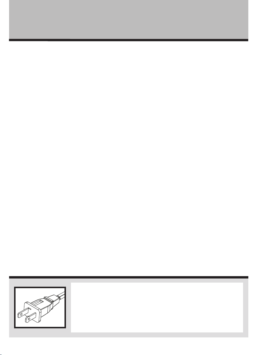
THIS APPLIANCE HAS A POLARIZED PLUG (one blade is wider than
the other). To reduce the risk of electric shock, this plug is intended to
fit in a polarized outlet only one way. If the plug does not fit fully in
the outlet, reverse the plug. If it still does not fit, contact a qualified
electrician to install the proper outlet.
DO NOT ATTEMPT TO MODIFY THIS PLUG OR DEFEAT THIS
SAFETY FEATURE IN ANY WAY.
ESTE PRODUCTO TIENE UN ENCHUFE POLARIZADO (una hoja es más
ancha que la otra). A fin de disminuir el riesgo de descarga eléctrica, este
enchufe está diseñado para insertarse en un tomacorriente polarizado en
un solo sentido. Si el enchufe no entra completamente en el tomacorriente,
inviértalo. Si aun así no entra, llame a un electricista calificado para
instalar un tomacorriente apropiado.
NO MODIFIQUE EL ENCHUFE NI ANULE ESTA FUNCION DE SEGURIDAD
DE NINGUNA MANERA.
Fig. 1
Fig. 1
Fig. 5
Control Panel
A
E
D
B
C
A. Power/Speed Button
B. Oscillation Button
C. Breeze/Sleep Mode Button
D. Timer Button
E. LED Display Panel
Fig. 5
Panel de control
A
E
D
B
C
A. Control de encendido/
velocidades
B. Botón de oscilación
C. Modo Brisas
D. Control de temporizador
E. Panel de pantalla LED
Fuse cover
Fig. 6
Metal ends
Fuse
Fig. 6
Cubierta
del fusible
extremos
metales
Fusible
Fig. 3
4 screws
(M4x12mm)
Fig. 3
4 tornillos
(M4x12mm)
Fig. 4
Cord Clip
Fig. 4
Sujetador del cable
Fig. 2
Circular
Alignment
Post
Circular
Alignment
Hole
Rectangular
Alignment
Post
Rectangular
Alignment
Hole
Fig. 2
Alineación del
palo circular
Alineación del
orificio circular
Alineación
del palo
rectangular
Alineación
del orificio
rectangular
HTF3211A_HTF3222A_15ESM1.indd 2 1/20/15 11:45 AM