INSTALLATION MANUAL

Contents
Steps for a Successful Installation 05
Tools & Items 11
Components 15
Installation Protocol 23
Cabinetry 24
Countertop 35
Appliances 40
Siliconing the Appliance and Countertop Seams 42
Faucet and Sink 44
Final Adjustments 46
Care & Maintenance 53
Pour la version française, veuillez
scanner le code QR suivant:
Para la versión en español,
escanee este código QR:
02 03

Steps for a
Successful
Installation
Please read the following importants points as they will greatly
facilitate the entire outdoor kitchen installation process.
04 05

Steps for a
Successful
Installation
Please read the following importants points as they will greatly
facilitate the entire outdoor kitchen installation process.
04 05

1. Prepare the Site
2. Planning for Equipment
Your outdoor kitchen should always be installed on a stable surface (patio/deck/
balcony/roof) which should be as near to level as drainage requirements allow.
All cabinets come standard with adjustable stainless steel legs. However, in instances
of extreme slope, or very large kitchens, footings may be needed to compensate if it
falls out of the adjustable range of the legs.
Your kitchen has been designed to be freestanding and does not need to be affixed
to the ground/wall. For extreme environments, such as high wind areas, we suggest
that your kitchen be secured to an appropriate support structure. Please consult with
your contractor/engineer for specifics.
Verify with your contractor/engineer to ensure that the surface is designed to support
the weight of the kitchen.
1.1
1.2
1.3
1.4
Although your outdoor kitchen is made of non-combustible materials and, as such,
does not require insulating jackets for the equipment, gas and live fire appliances
have very specific restrictions for safe installation and use, which can vary from one
jurisdiction to another. Please review the owner’s manuals for all appliances before
installation and ensure the work is done by a professional in accordance with local
codes.
Your outdoor kitchen has been designed for a specific appliance. Before ordering
your equipment, please verify that it matches with the model number listed on your
final kitchen design document.
2.1
2.2
3. Planning for Services (Gas/Electrical/Plumbing)
Conduit holes and access panels are included in most cabinets to make service planning
and implementation as easy as possible.
As with equipment, local codes have specific requirements and restrictions for all
services. Please ensure that planning and installation is performed by a locally licensed
tradesperson.
CIRCULAR CONDUIT HOLE
REMOVABLE
ACCESS PANEL
06 07
4. Before Unpacking your Kitchen
Your outdoor kitchen ships with cabinets fully assembled, making cabinet installation
quick and straightforward. However, within the cabinets themselves there are accessories
and smaller pieces that can easily be misplaced on a busy job site. As such, we suggest
taking special care to locate these pieces during unpacking so that they can be set aside
for when they are needed during the installation process.
In our experience, parts that can be lost in the shuffle include:
Toe Kicks for End Panel
and for Finished Back Panel
Each end panel will include one, 2-piece, toe
kick. Cabinets with finished back panels will
include a one, 2-piece, toe kick as well.
Corner Toe Kick
Each end panel will include two toe kick corners.
Front Toe Kicks
Each cabinet includes one 2-piece front
toe kick.
Toe Kick Clips
These plastic clips allow the front toe kicks to
be installed onto the cabinets legs. These are
packed along with the installation hardware
(screws/nuts/bolts) for each kitchen.
Extra Hardware/Magnets/Bumpers
Maintenance kit.
Grill Side Trims
Allows the cabinet to professionally
integrate with the appliance.
08 09

Tools & Items
10 11

Tools & Items
10 11
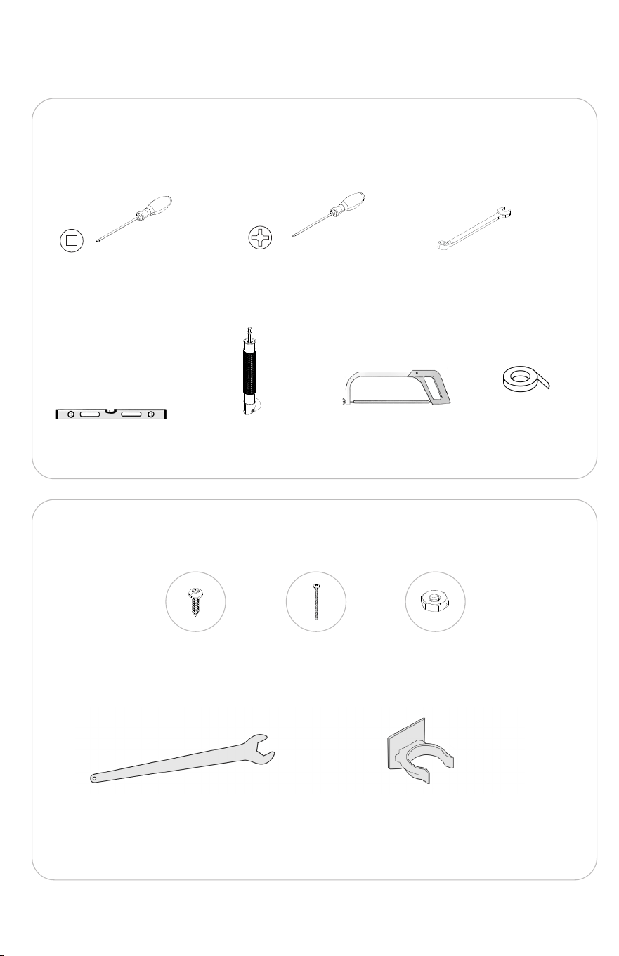
TOOLS REQUIRED
ITEMS PROVIDED
Outdoor Kitchen
Robertson #2 Screwdriver
and/or drill bit
#8 Screws
Leg Wrench
Toe Kick Clips
2” 8-32 Bolts
Phillips #2 Head Screwdriver
and/or drill bit
Right Angle Adapter or Drill
(recommended)
Metal Hacksaw
Nuts
Level
Masking Tape
3/8 Wrench
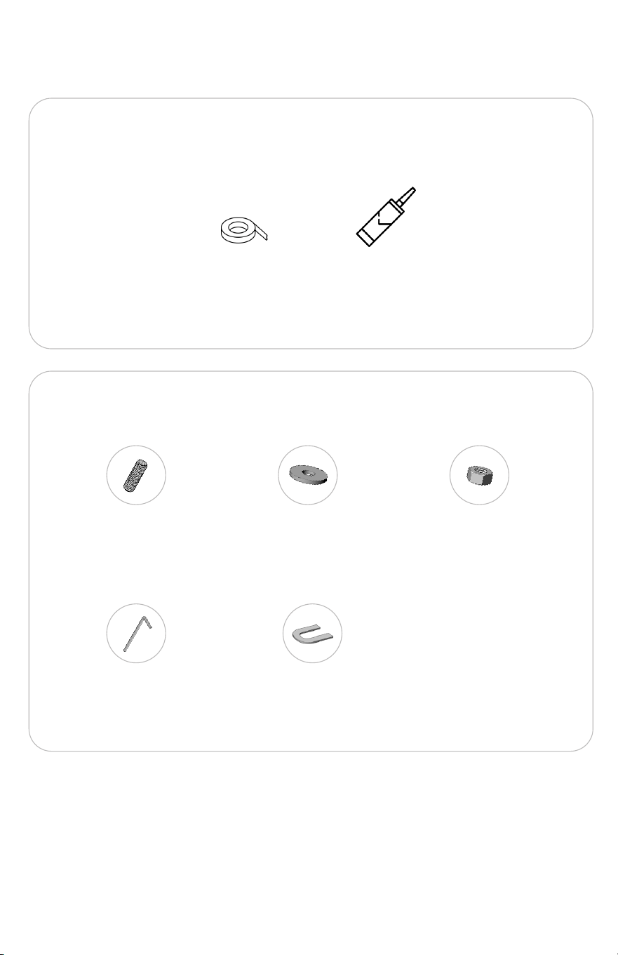
TOOLS REQUIRED
ITEMS PROVIDED
Countertop
Masking Tape
M6 studs
Silicone
Washers
ShimsAllen Hex Key
Nuts (m6)
12 13
TOOLS REQUIRED
ITEMS PROVIDED
Outdoor Kitchen
Robertson #2 Screwdriver
and/or drill bit
#8 Screws
Leg Wrench
Toe Kick Clips
2” 8-32 Bolts
Phillips #2 Head Screwdriver
and/or drill bit
Right Angle Adapter or Drill
(recommended)
Metal Hacksaw
Nuts
Level
Masking Tape
3/8 Wrench
TOOLS REQUIRED
ITEMS PROVIDED
Countertop
Masking Tape
M6 studs
Silicone
Washers
ShimsAllen Hex Key
Nuts (m6)
12 13

Components
14 15

Components
14 15
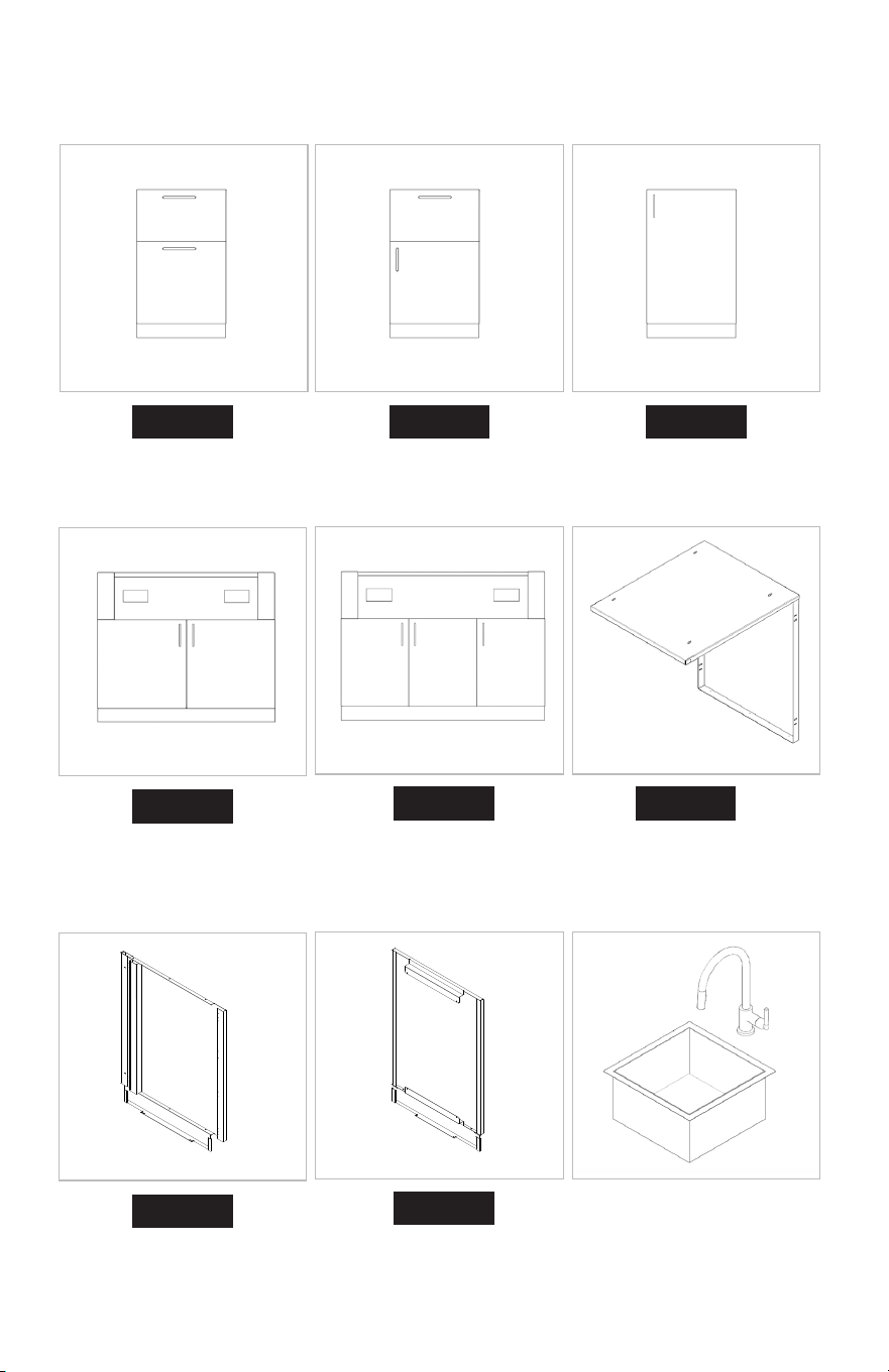
Attaching Front
Storage & Refuse Cabinet Storage Cabinet
A B C
D
END
E
BCKP
FRDG
Sink Cabinet
Grill Base Cabinet for
32” Grill
End panels
Kit for Refrigerator (24”)
Grill Base Cabinet
for 40” Grill
Back panels
Outdoor Kitchen
Sink & Faucet
Countertop Pieces
BL-L1
BL-M32
BL-M40
BL-R2
BL-R2S
BL-R1
16 17
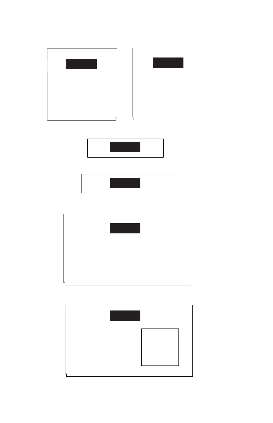
Appendix
A
A
A
D
D
D
B
B
BB
FRDG
FRDG
A
A
D
D
C
C
B
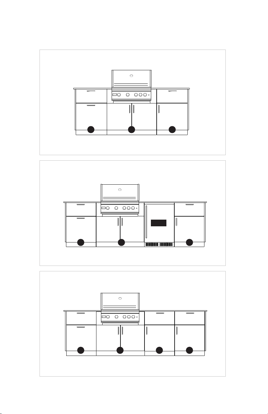
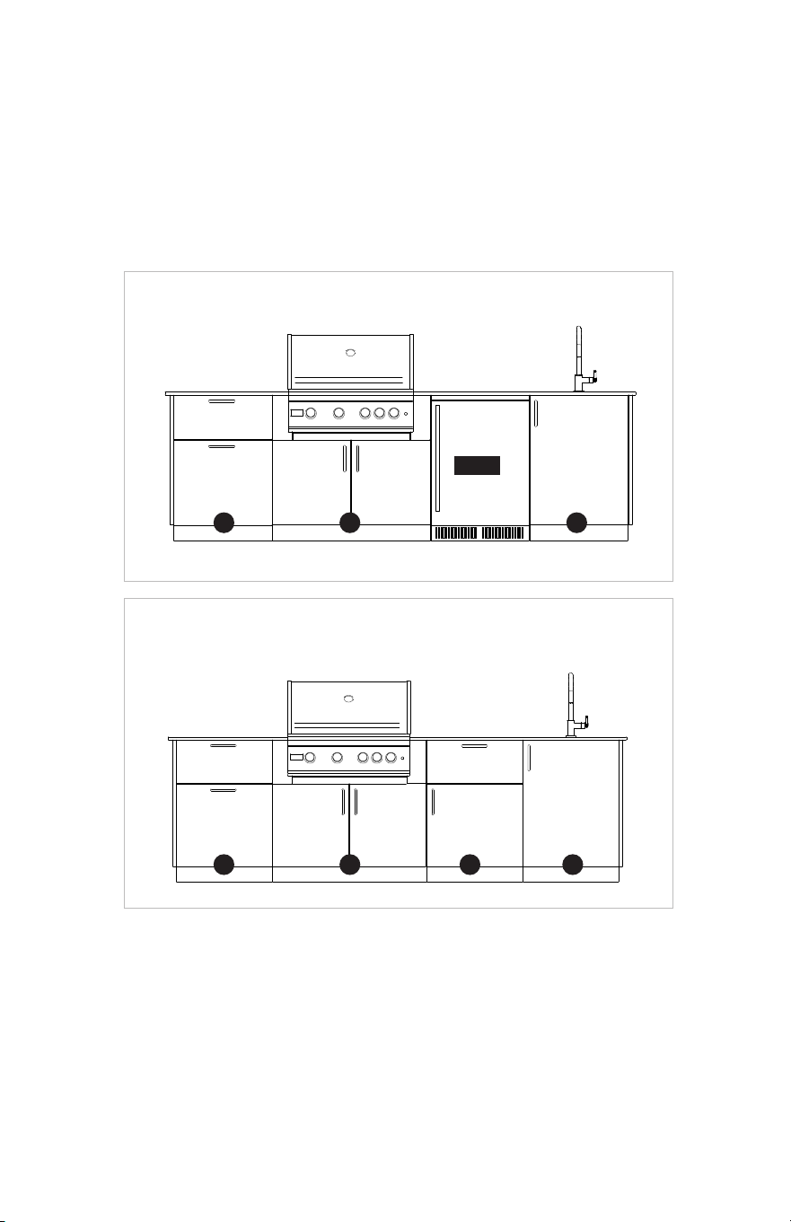
SUNRISE 32
MORNING GLOW 32
GOLDEN HOUR 32
SUNSET 32
HIGH NOON 32
18 19
Appendix
A
A
A
D
D
D
B
B
BB
FRDG
FRDG
A
A
D
D
C
C
B
SUNRISE 32
MORNING GLOW 32
GOLDEN HOUR 32
SUNSET 32
HIGH NOON 32
18 19
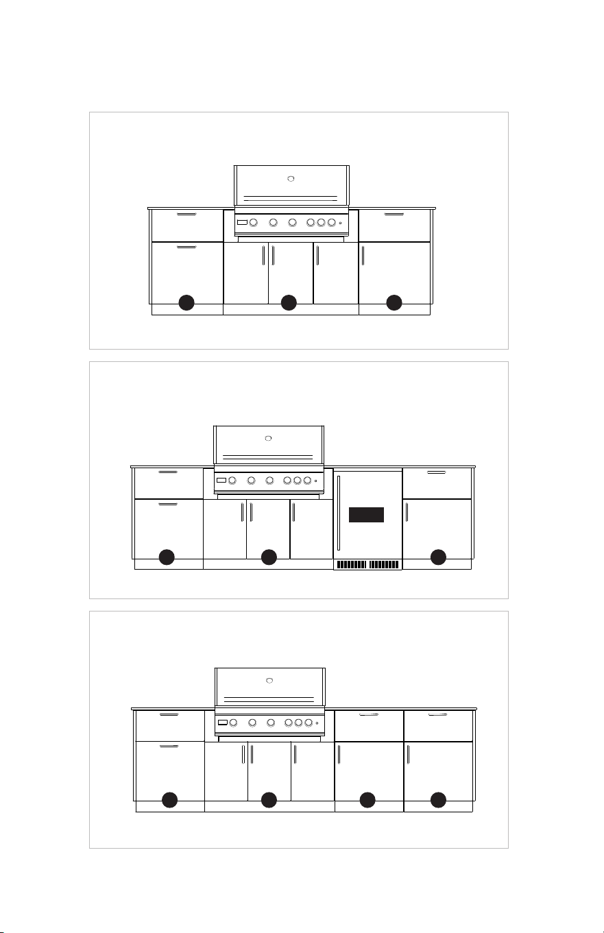
SUNRISE 40
MORNING GLOW 40
GOLDEN HOUR 40
HIGH NOON 40
SUNSET 40
A
A
A
E
E
E
B
B
BB
FRDG
FRDG
A
A B
E
E
C
C
20 21
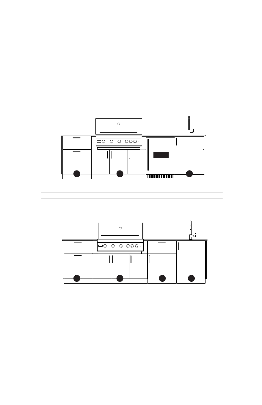
SUNRISE 40
MORNING GLOW 40
GOLDEN HOUR 40
HIGH NOON 40
SUNSET 40
A
A
A
E
E
E
B
B
BB
FRDG
FRDG
A
A B
E
E
C
C
20 21

For safety, efficiency and best results, it is strongly
suggested that installation be performed by 2 people.
Installation
Protocol
22 23

For safety, efficiency and best results, it is strongly
suggested that installation be performed by 2 people.
Installation
Protocol
22 23
Cabinetry
1.1 Measure out the installation area and mark the kitchen location (Please reference the
Appendix on pages 18 to 21 to find the plan of your specific layout).
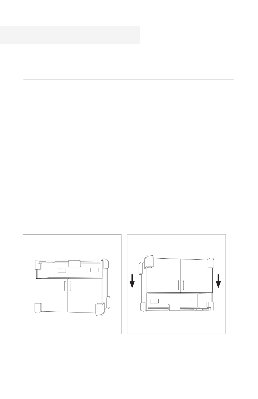
1.2 Unpack your kitchen. Cabinets should be manipulated by 2 persons.
1. Getting Started
Unbox the cabinets while leaving any shrink wrap and protective foam corners in
place.
ii) Remove the internal components and any small boxes, when applicable, through
the top of the cabinet (paying special attention to small parts listed on pages 08-09).
Each cabinet comes fully assembled and is packed in its own box, which is numbered
corresponding to the final design plans.
1.3 Flip the cabinets upside down, resting them on the protective foam corners to avoid
damage.
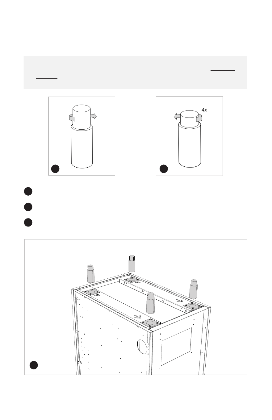
2. Cabinet Legs
2.1 Attach the stainless steel leveling legs to cabinets:
For best results, we strongly suggests starting with the leveling legs as low as
possible, leaving the ability to raise them, to level, later in the process.
Turn the leg clockwise until the leg is as short as it can be.
When the maximum is reached, stop and turn counterclockwise 4 times.
1
1
2
2
3
Screw the legs onto the mounting plates on the bottom of the cabinet.
3
24 25
Cabinetry
1.1 Measure out the installation area and mark the kitchen location (Please reference the
Appendix on pages 18 to 21 to find the plan of your specific layout).
1.2 Unpack your kitchen. Cabinets should be manipulated by 2 persons.
1. Getting Started
Unbox the cabinets while leaving any shrink wrap and protective foam corners in
place.
ii) Remove the internal components and any small boxes, when applicable, through
the top of the cabinet (paying special attention to small parts listed on pages 08-09).
Each cabinet comes fully assembled and is packed in its own box, which is numbered
corresponding to the final design plans.
1.3 Flip the cabinets upside down, resting them on the protective foam corners to avoid
damage.
2. Cabinet Legs
2.1 Attach the stainless steel leveling legs to cabinets:
For best results, we strongly suggests starting with the leveling legs as low as
possible, leaving the ability to raise them, to level, later in the process.
Turn the leg clockwise until the leg is as short as it can be.
When the maximum is reached, stop and turn counterclockwise 4 times.
1
1
2
2
3
Screw the legs onto the mounting plates on the bottom of the cabinet.
3
24 25
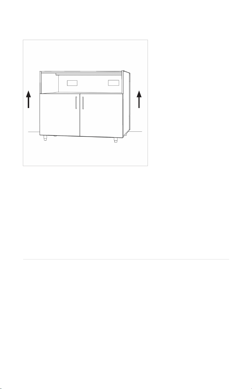
2.2 Flip the cabinets right side up so that they are sitting on the legs.
2.3 Remove the shrink wrap and protective foam corners.
2.4 Arrange the cabinets in order, left to right, accordingly to the plan of your specific
kitchen layout.
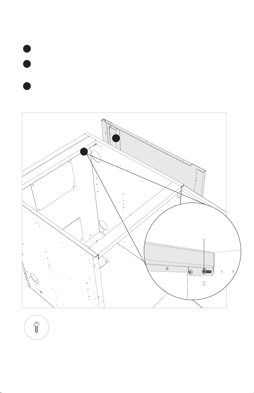
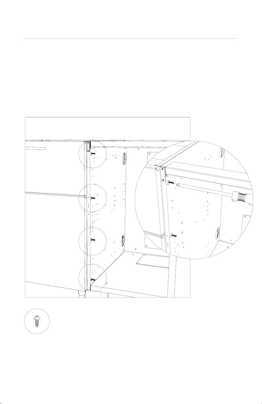
3. End Panels to the Cabinets
3.1 Locate and unpack the two end panels (being careful to set the toe kicks
somewhere safe for use later).
3.2 From inside the leftmost cabinet, attach the end panel using 4x n°8 screws -
two at the top and two at the bottom.
3.3 From inside the rightmost cabinet, attach the end panel using 4x n°8 screws -
two at the top and two at the bottom.
TO NOTE
These end panels are reversible, so they will each fit on either end of the layout.
The vertical channel on the inside of the end panel should be aligned towards
the back.
The front screw holding the back top box in place will need to be removed to
allow the endpanel to sit properly.
Attaching Front
N°8 SCREW
1
2
2
3
3
REMOVE THIS
SCREW
26 27
2.2 Flip the cabinets right side up so that they are sitting on the legs.
2.3 Remove the shrink wrap and protective foam corners.
2.4 Arrange the cabinets in order, left to right, accordingly to the plan of your specific
kitchen layout.
3. End Panels to the Cabinets
3.1 Locate and unpack the two end panels (being careful to set the toe kicks
somewhere safe for use later).
3.2 From inside the leftmost cabinet, attach the end panel using 4x n°8 screws -
two at the top and two at the bottom.
3.3 From inside the rightmost cabinet, attach the end panel using 4x n°8 screws -
two at the top and two at the bottom.
TO NOTE
These end panels are reversible, so they will each fit on either end of the layout.
The vertical channel on the inside of the end panel should be aligned towards
the back.
The front screw holding the back top box in place will need to be removed to
allow the endpanel to sit properly.
Attaching Front
N°8 SCREW
1
2
2
3
3
REMOVE THIS
SCREW
26 27
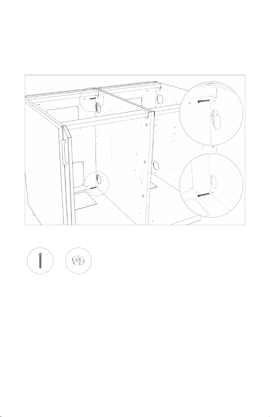
4. Attaching the Cabinets Together
4.1 Refer to your specs sheet (included in packing slip) to arrange your cabinets into
proper layout by following the labels on each cabinet.
4.2 Connect cabinets to each other in the front using 4x n°8 screws.
DO NOT OVERTORQUE.
N°8 SCREW
Attaching Front
Attaching Front
4.3 Attach the back of the cabinets together using 2x 2” long 8-32 bolts and nuts.
This is done through the holes in located at the top and bottom of the back of the cabinets.
2 IN. 8-32 BOLT
NUT
28 29
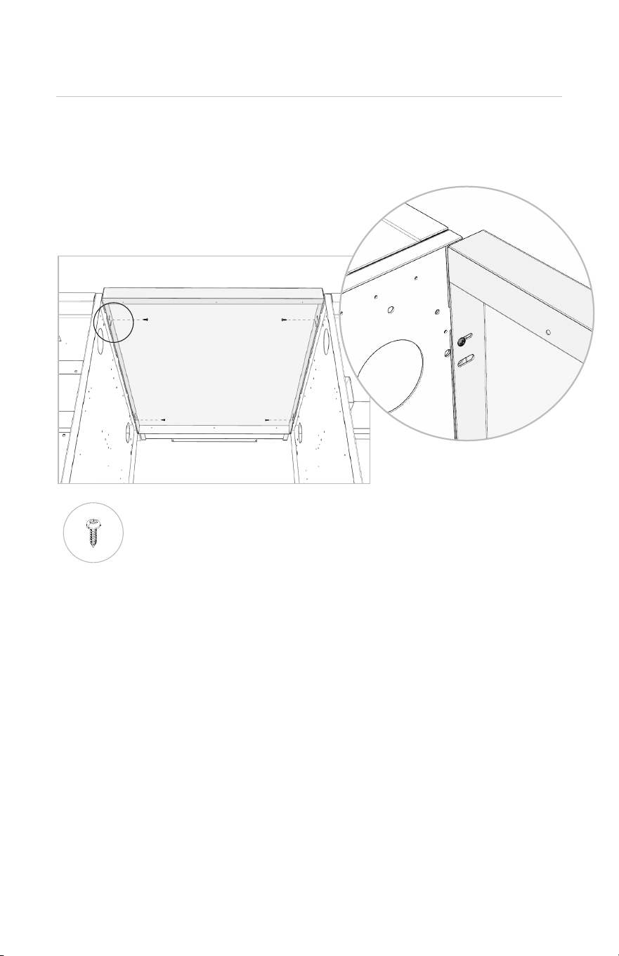
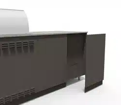
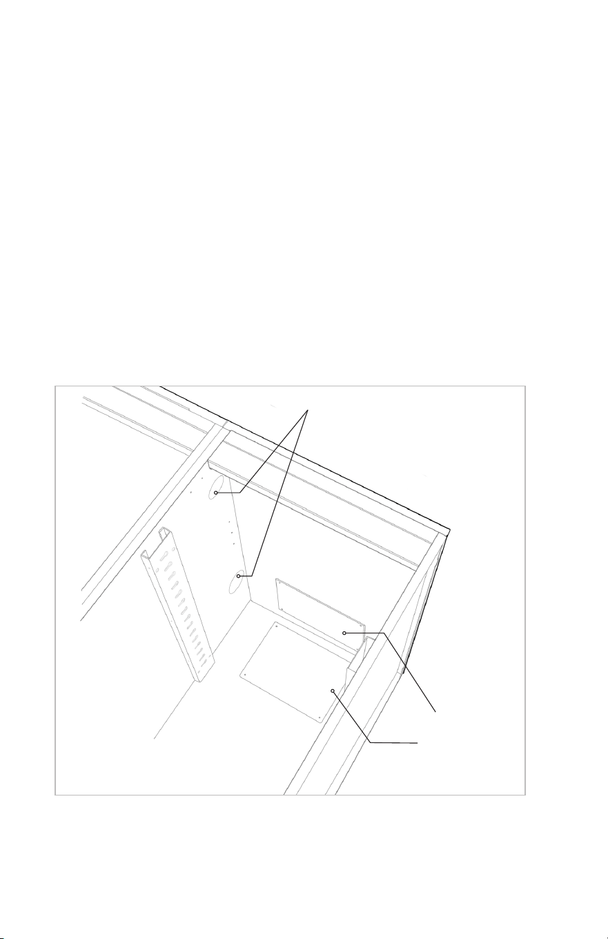
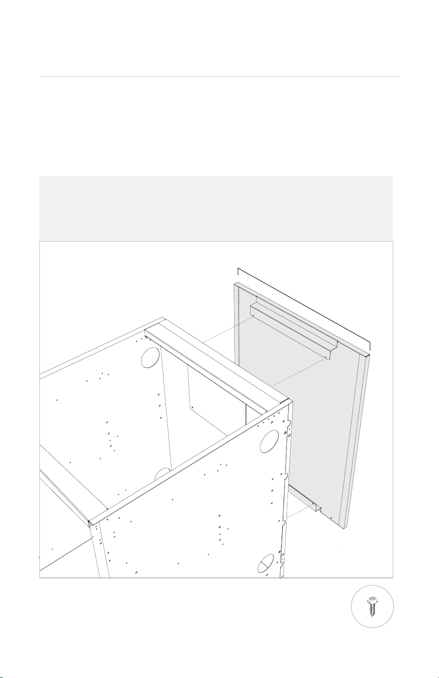
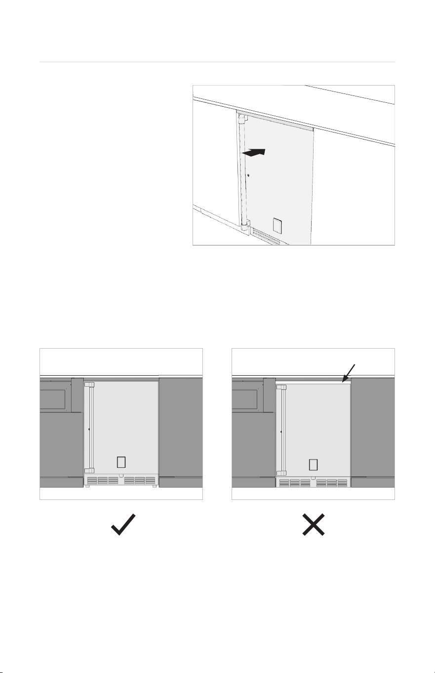
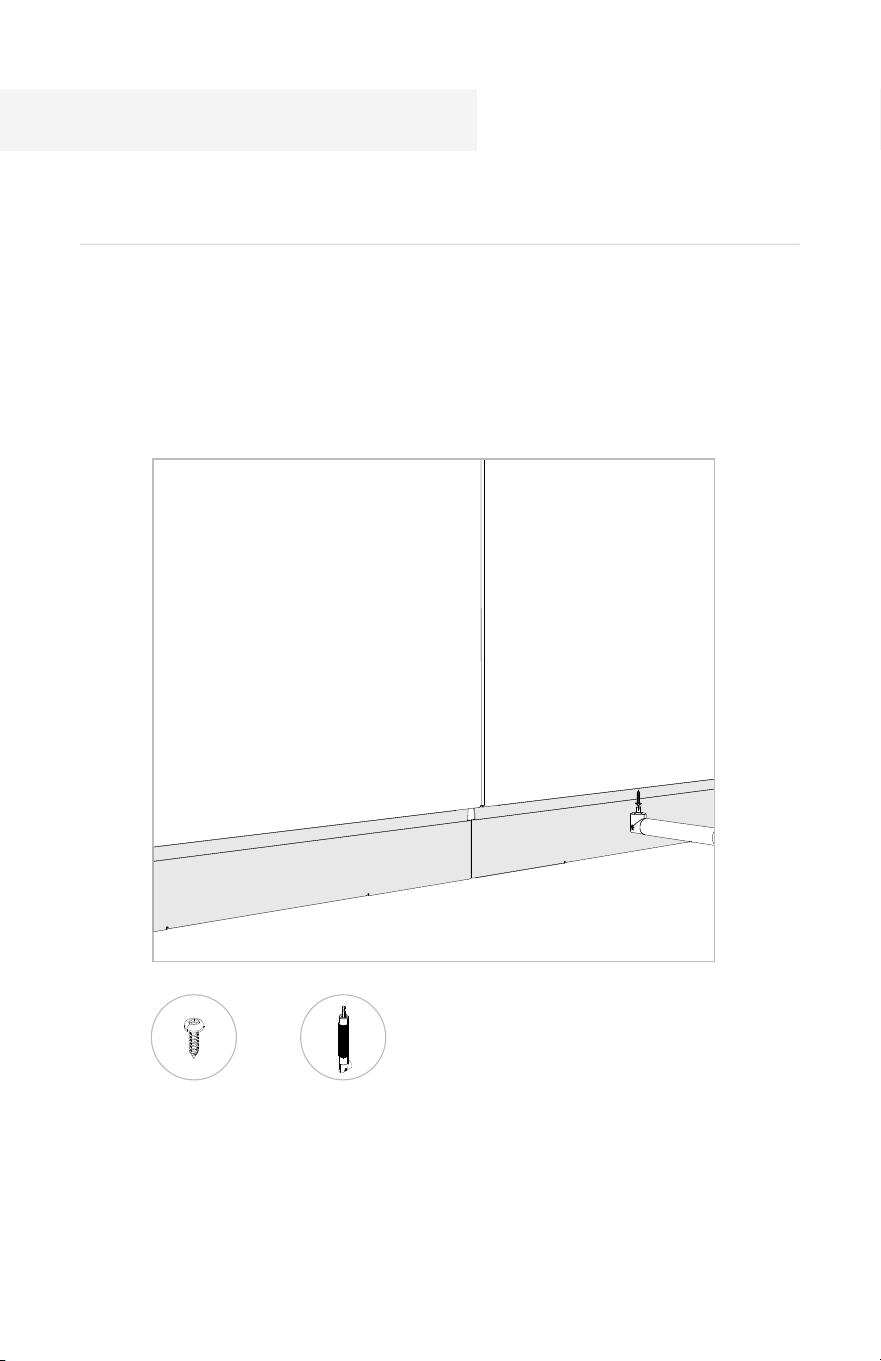
5.1 If your kitchen features undercounter refrigeration, install the Back Panel to the adjacent
cabinets using 4x n°8 screws. The screws should be installed towards the front. See in the
below figure.
Note: If your kitchen does not include finished back panels, it is normal that this fridge
back panel will sit slightly behind the rest of the cabinets once installed.
5. Undercounter Appliance Kit (if applicable)
N°8 SCREW
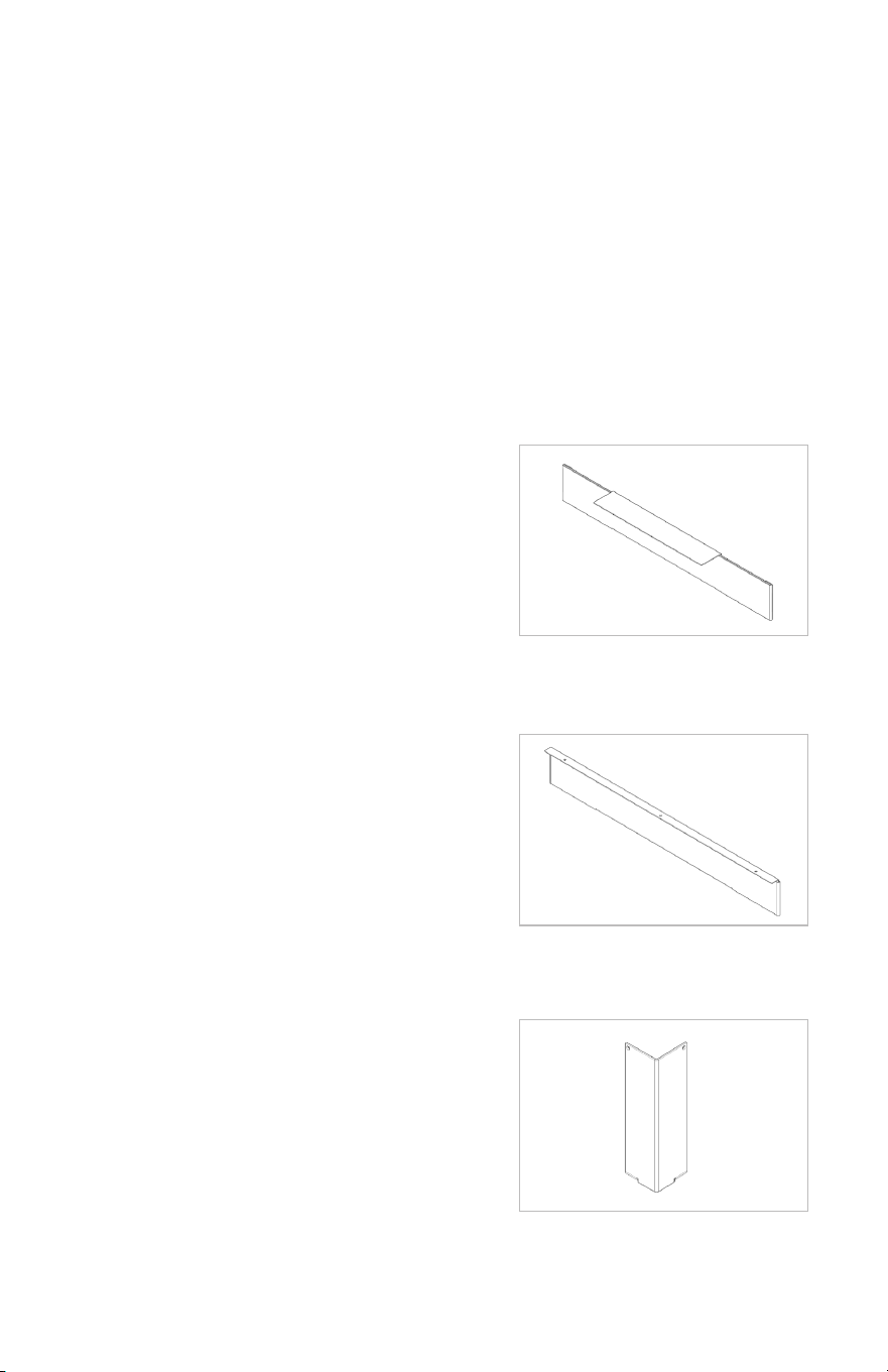
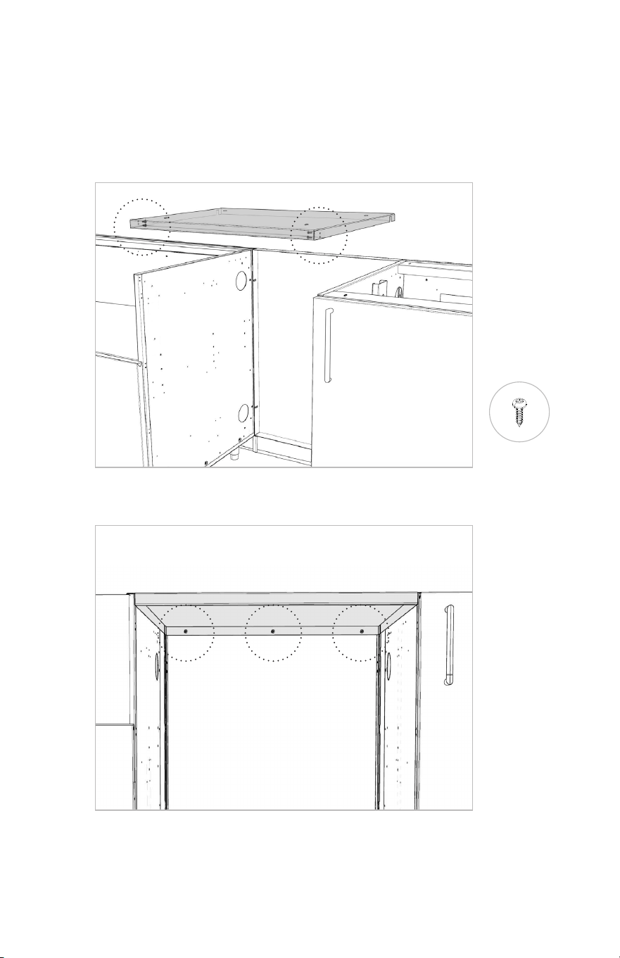
5.2 Install the top panel with the flat section facing up (it will be supporting the countertop),
using 7x n°8 screws (2x on each side and 3x at the back). Fasten from underneath.
N°8 SCREW
i)
ii)
30 31
5.1 If your kitchen features undercounter refrigeration, install the Back Panel to the adjacent
cabinets using 4x n°8 screws. The screws should be installed towards the front. See in the
below figure.
Note: If your kitchen does not include finished back panels, it is normal that this fridge
back panel will sit slightly behind the rest of the cabinets once installed.
5. Undercounter Appliance Kit (if applicable)
N°8 SCREW
5.2 Install the top panel with the flat section facing up (it will be supporting the countertop),
using 7x n°8 screws (2x on each side and 3x at the back). Fasten from underneath.
N°8 SCREW
i)
ii)
30 31

Once all cabinets are attached together, make sure the whole kitchen is leveled properly.
For best results, it is strongly suggested starting with the leveling legs as low as
possible, leaving the ability to raise them, to level, later in the process.
If your kitchen needs to be leveled, follow these helpful steps :
LEVEL
LEG WRENCH
6.1 Using a level, locate the cabinet which is sitting the highest.
This will let you know the high point of the floor.
6.2 Using a level, adjust the feet so that this, highest, cabinet is
sitting perfectly level with all four of its feet firmly on the floor (use
the leg wrench, if needed, when adjusting the back legs of the
cabinets). This will be your starting point.
6.3 Using a level, work outwards from this starting point, one
cabinet at a time, raising the adjustable feet as needed to ensure
each subsequent cabinet is raised to the same height as the
starting point.
6.3 Ensure ALL four legs for each subsequent cabinet are firmly
on the floor.
6.4 Using a level, verify that the entire kitchen is now level.
Proper leveling is important since it will create a flat surface for countertop
installation. It will also create even gaps between adjacent doors and drawers.
6. Leveling 7. Back Panels to the Cabinets (if applicable)
Attaching Front
7.1 Locate and unpack the finished back panels (being careful to set the toe kicks
somewhere safe for use later)
7.2 From inside the cabinets, attach each respective back panel using 4x n°8 screws -
two at the top and two at the bottom.
IMPORTANT
The backpanels are NOT reversible. In order to ensure they are installed correctly,
please pay special attention that the top of the back panel is the flat, hole-free side.
TOP
N°8 SCREW
32 33
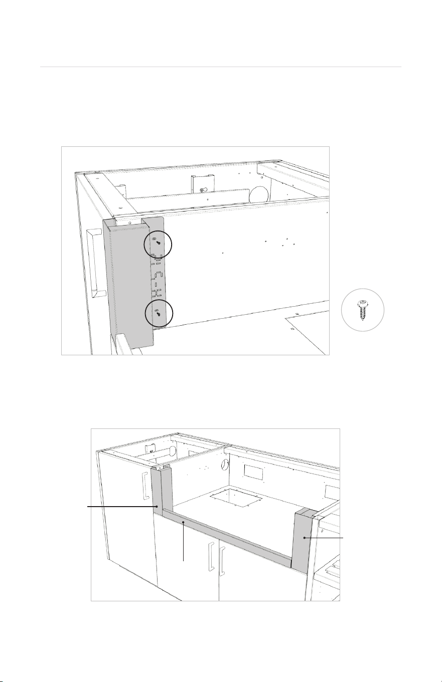
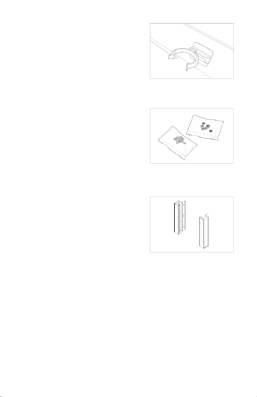
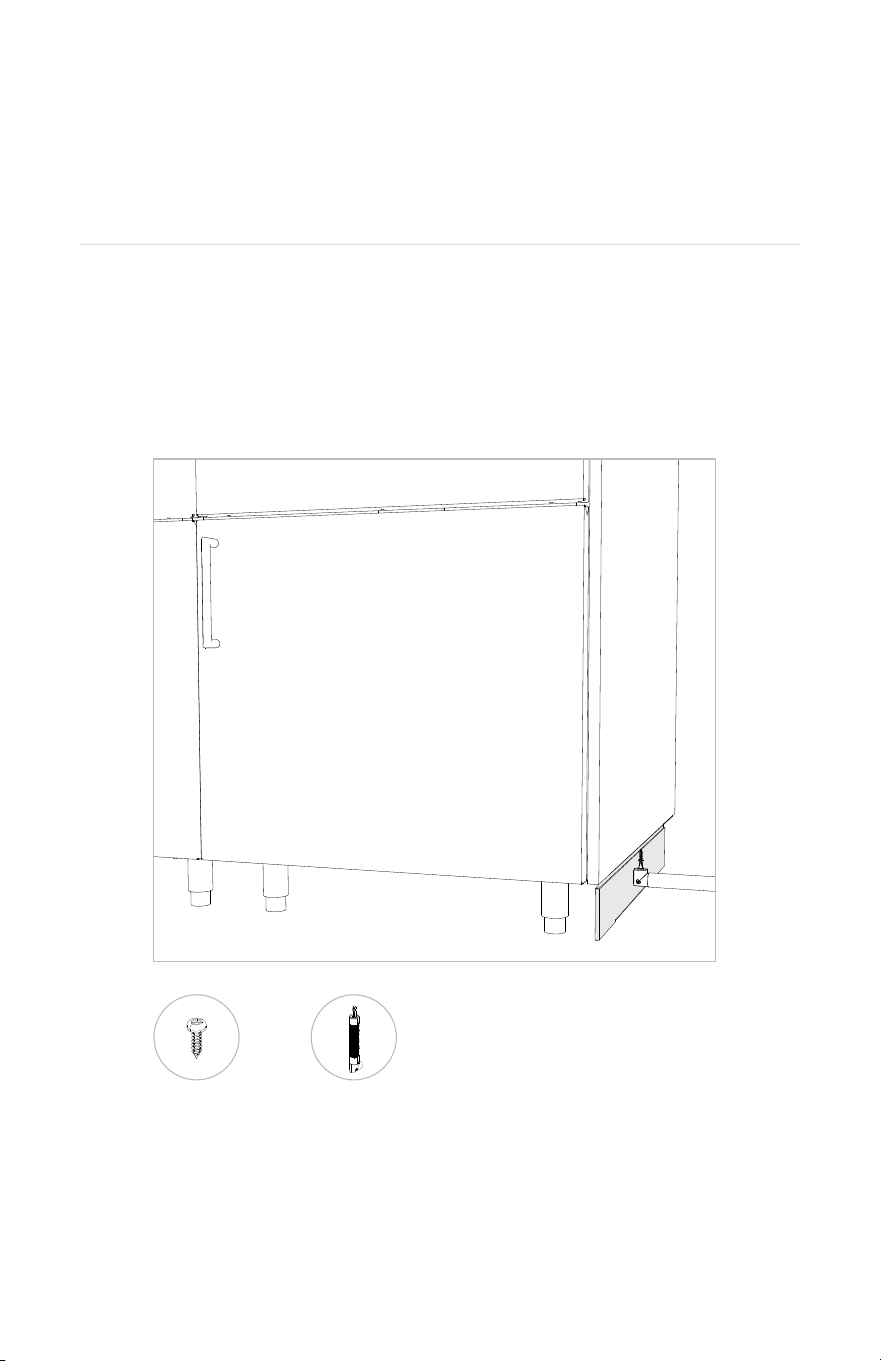
8. Installing the Trim Kit
8.1 Remove the shipping bracket that is installed on the cabinet and install the Side Trims
using n°8 screws on both sides.
SIDE TRIM
SIDE TRIM
BOTTOM TRIM
Once all installed, the trim kit should look like this.
N°8 SCREW
Once your cabinets are fully leveled and secured, your kitchen is ready to receive
countertop.
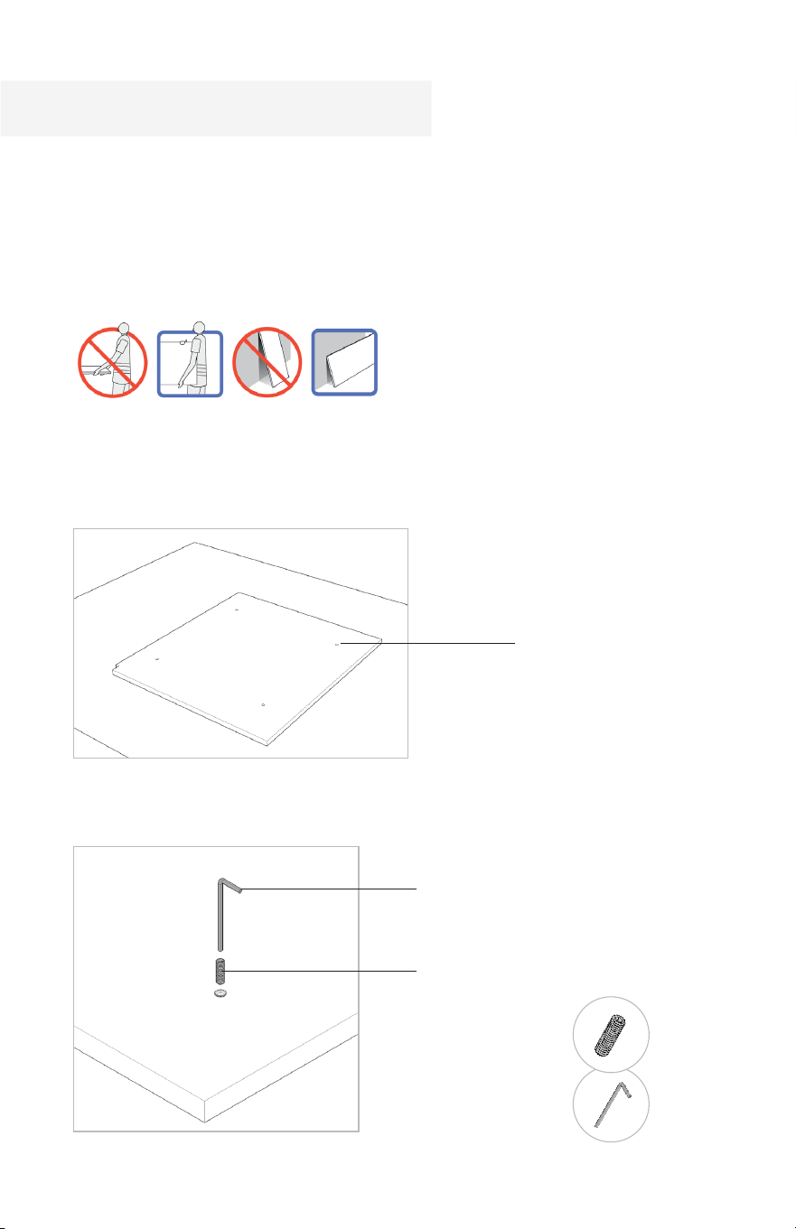
Take extra care when manipulating the countertop pieces as they are fragile. Make
sure to transport the pieces vertically, with at least two people.
1.1 Starting with the piece that is going on the left of the kitchen, place it on a protected
surface, threaded holes facing up.
1.2 Using an Allen Hex Key (provided), screw the M6 studs into each threaded hole.
Allen Hex Key
Threaded Hole
M6 Stud
ALLEN HEX KEY
M6 STUD
Countertop
34 35
8. Installing the Trim Kit
8.1 Remove the shipping bracket that is installed on the cabinet and install the Side Trims
using n°8 screws on both sides.
SIDE TRIM
SIDE TRIM
BOTTOM TRIM
Once all installed, the trim kit should look like this.
N°8 SCREW
Once your cabinets are fully leveled and secured, your kitchen is ready to receive
countertop.
Take extra care when manipulating the countertop pieces as they are fragile. Make
sure to transport the pieces vertically, with at least two people.
1.1 Starting with the piece that is going on the left of the kitchen, place it on a protected
surface, threaded holes facing up.
1.2 Using an Allen Hex Key (provided), screw the M6 studs into each threaded hole.
Allen Hex Key
Threaded Hole
M6 Stud
ALLEN HEX KEY
M6 STUD
Countertop
34 35
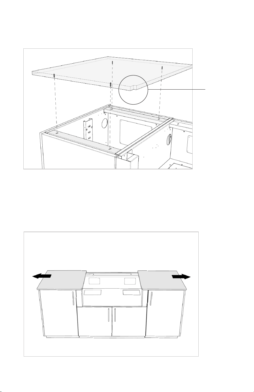
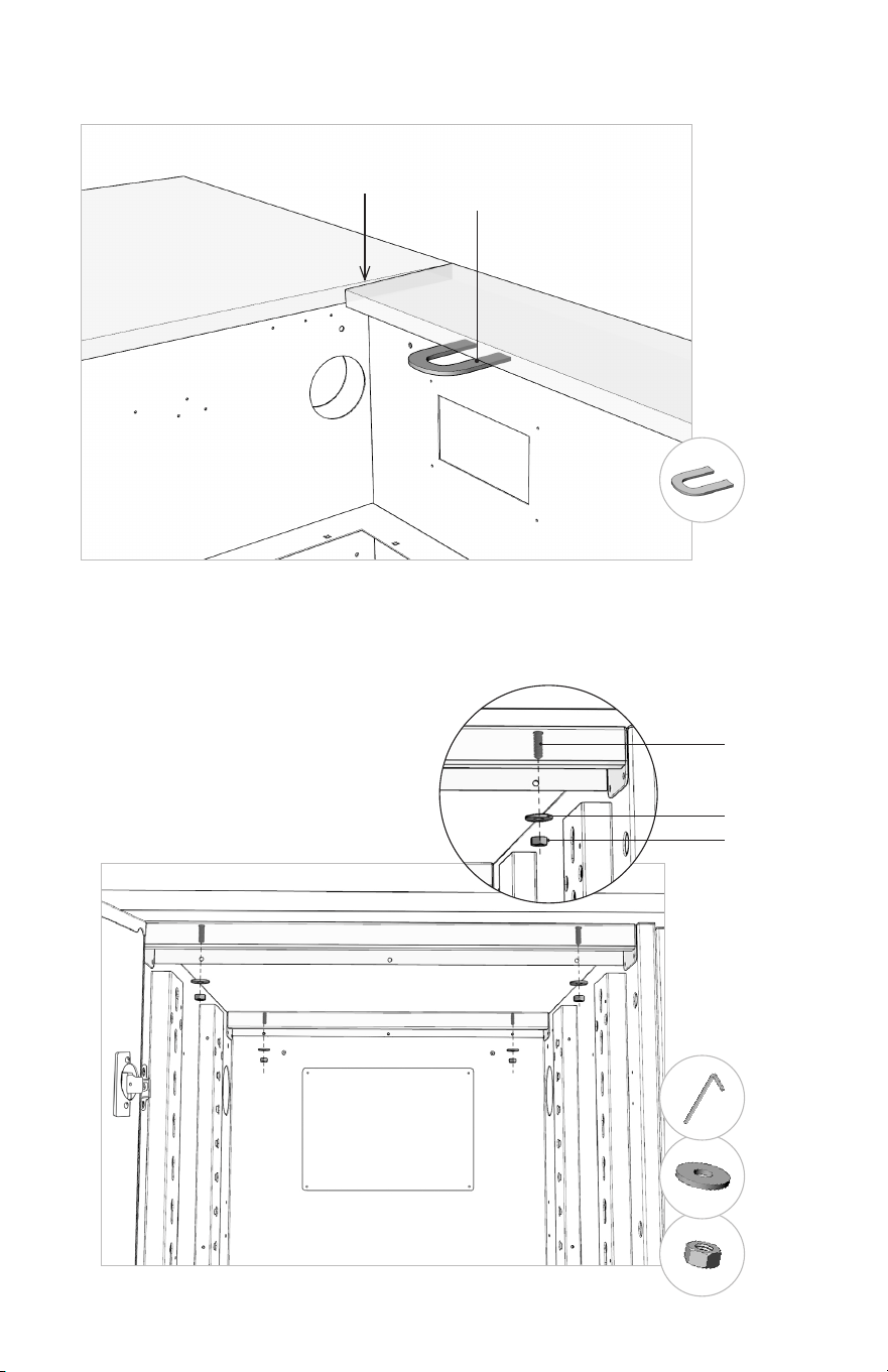
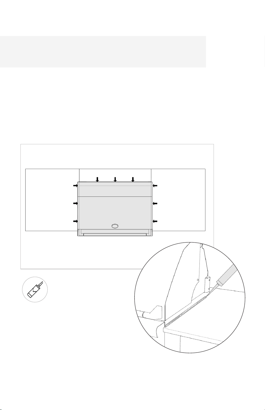
1.3 Install the countertop piece on the kitchen by carefully moving it around until the M6
studs align into the cabinet slots. If the counter piece has a notch, make sure the notch is
on the front of the kitchen.
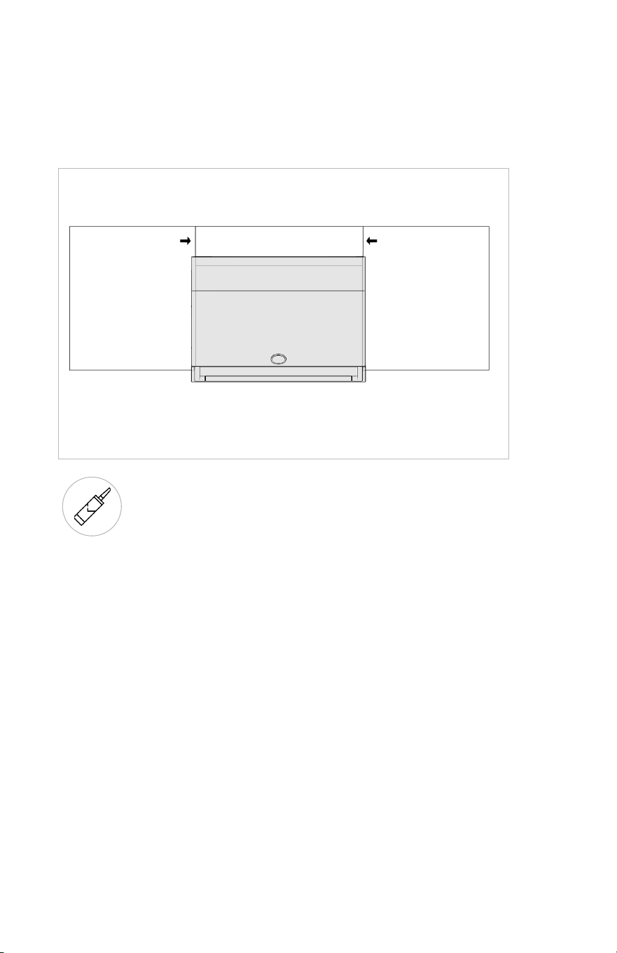
1.5 Push each of the side sections slightly outward to allow for the center counter piece to
be moved into place.
1.4 Repeat the previous steps for the counter piece that is going on the right of the kitchen.
notch
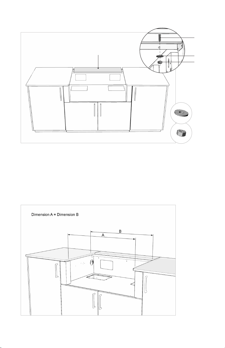
1.6 Place the center piece and loosely attach it with the provided washers and nuts.
Center Piece
1.7 Adjust entire countertop front and back overhang as needed based on your
configuration.
1.8 Carefully bring in the pieces towards the center piece. Make sure that the width
opening for appliance is consistent, from front to back (see diagram below).
NUT
WASHER
Threaded Stud
Washer
Nut
36 37
1.3 Install the countertop piece on the kitchen by carefully moving it around until the M6
studs align into the cabinet slots. If the counter piece has a notch, make sure the notch is
on the front of the kitchen.
1.5 Push each of the side sections slightly outward to allow for the center counter piece to
be moved into place.
1.4 Repeat the previous steps for the counter piece that is going on the right of the kitchen.
notch
1.6 Place the center piece and loosely attach it with the provided washers and nuts.
Center Piece
1.7 Adjust entire countertop front and back overhang as needed based on your
configuration.
1.8 Carefully bring in the pieces towards the center piece. Make sure that the width
opening for appliance is consistent, from front to back (see diagram below).
NUT
WASHER
Threaded Stud
Washer
Nut
36 37
1.9 Adjust with shims (provided) if necessary.
Shim
Gap
1.10 Install the washers to the M6 studs.
Using the Allen Hex Key, hold the M6
studs and install the nuts on all counter
pieces, and fully tighten to fix them all
in place.
DO NOT OVERTORQUE
NUT
WASHER
SHIMS
Threaded Stud
Washer
Nut
ALLEN HEX KEY
PRO-TIP
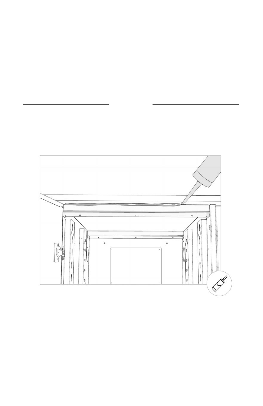
Although our cabinetry is fully enclosed, a bead of silicone can be added around the
perimeter of the kitchen to optimize the preventation of water infiltration.
SILICONE
38 39
1.9 Adjust with shims (provided) if necessary.
Shim
Gap
1.10 Install the washers to the M6 studs.
Using the Allen Hex Key, hold the M6
studs and install the nuts on all counter
pieces, and fully tighten to fix them all
in place.
DO NOT OVERTORQUE
NUT
WASHER
SHIMS
Threaded Stud
Washer
Nut
ALLEN HEX KEY
PRO-TIP
Although our cabinetry is fully enclosed, a bead of silicone can be added around the
perimeter of the kitchen to optimize the preventation of water infiltration.
SILICONE
38 39
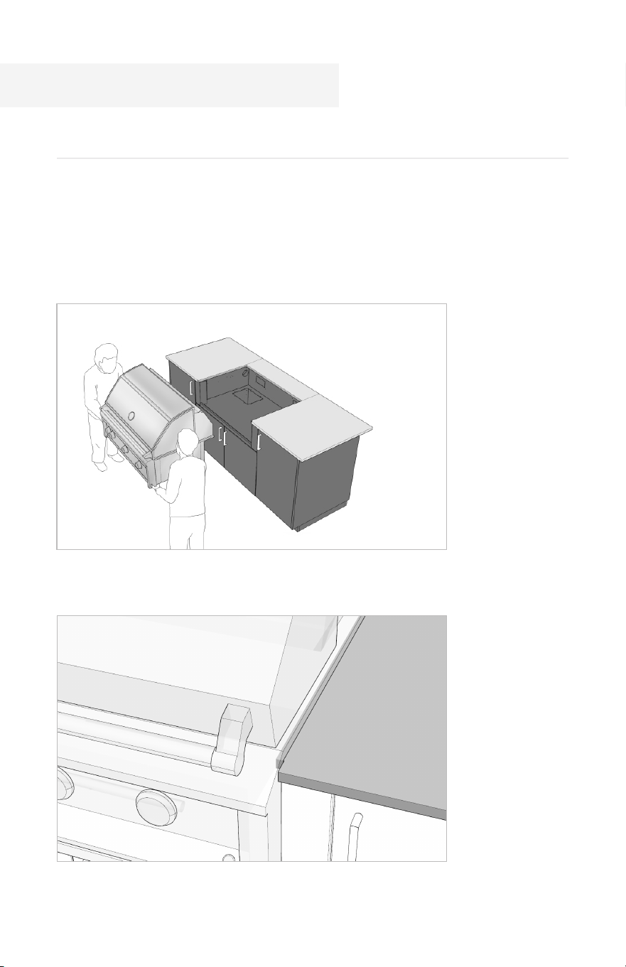
The built-in grill is designed to be installed ON TOP of the countertop. Do not place the
grill on the cabinet shelf. Failure to comply could result in damage to the structure of
this cabinet. Please review the owner’s manuals for all appliances before installation and
ensure the work is done by a professional in accordance with local codes.
1.1 Transport the grill to the cabinet with 2 persons.
1.2 Make sure that your grill sits on the countertop and meets the notch on the front.
1. Grill
Appliances
2. Undercounter Appliance (if applicable)
2.1 Slide the undercounter
appliance into its opening.
2.2 If necessary, use the adjustable legs on the undercounter appliance to create a small,
consistent reveal just below the top panel.
As with equipment, local codes have specific requirements and
restrictions for all services. Please ensure that installation is
performed by a locally licensed tradesperson.
40 41
1. Seal the seams around the appliance, where it meets the countertop, using the silicone.
Having silicone around the appliance avoids unnecessary water infiltration. It also has the
added benefit of keeping built-in equipment solidly in place during use, and can be easily
cut through using a utility knife should the need for removing the equipment (for service,
moving, or replacement) ever arise.
SILICONE
Siliconing the Appliance and
Countertop Seams
2. Seal the seams between counter pieces for best performance and results.
3. Remove any excess of silicone using a damp cloth.
SILICONE
42 43

1. Faucet
Please scan this QR code below to find the instructions.
Faucet and Sink
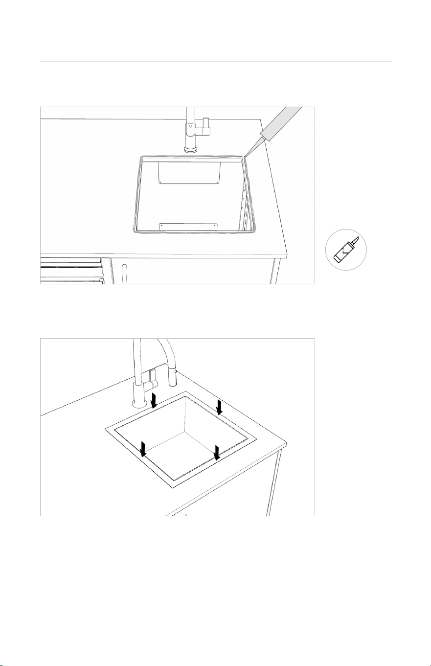
1. Apply a bead of silicone along the edge of the cut-out.
2. Center the sink into the opening and drop it in place. Apply even pressure to all sides.
3. Remove any excess silicone with a damp cloth.
2. Sink
SILICONE
As with equipment, local codes have specific requirements and restrictions for
all services. Please ensure that installation is performed by a locally licensed
tradesperson.
44 45
1. Faucet
Please scan this QR code below to find the instructions.
Faucet and Sink
1. Apply a bead of silicone along the edge of the cut-out.
2. Center the sink into the opening and drop it in place. Apply even pressure to all sides.
3. Remove any excess silicone with a damp cloth.
2. Sink
SILICONE
As with equipment, local codes have specific requirements and restrictions for
all services. Please ensure that installation is performed by a locally licensed
tradesperson.
44 45
Final Adjustments
1. Back Toe Kicks
Using a 90-degree drill bit or short screwdriver, install the toe kicks to all back panels
using 3x n°8 screws per back panels.
2. End Toe Kicks
Using a 90-degree drill bit or short screwdriver, install the toe kicks to both
end panels using 3x n°8 screws per back panels.
N°8 SCREW
90-DEGREE DRILL BIT OR
SHORT SCREWDRIVER
90-DEGREE DRILL BIT OR
SHORT SCREWDRIVER
N°8 SCREW
46 47
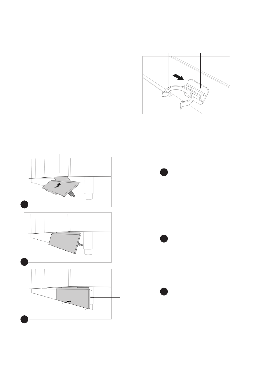
3. Front Toe Kicks
3.1 Install the Toe Kick Clips to the Front Toe
Kicks by sliding them into the bracket (see
right image).
3.2 Attach the Front Toe Kicks by resting the top section on the bottom lip of the cabinet
and then attaching the Clips to the stainless steel legs (see images below).
Hang the top portion of
the Front Toe Kick onto the
cabinet frame.
Rotate the assembly.
Toe Kick Clips attach to
stainless steel legs.
CABINET FRAME
BRACKETTOE KICK CLIP
TOP PORTION
LEG
TOE KICK CLIP
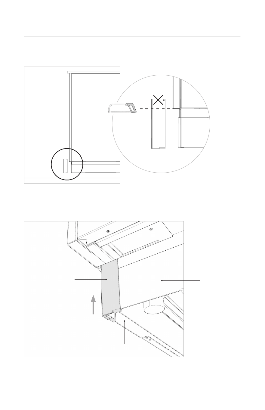
3.3 Remove tape from toe kicks (including back and side toe kicks), allowing front plates
to slide down to meet the ground.
1
1
2
2
3
3
4.1 Measure Corner Toe Kick height and cut to size with hacksaw, keeping the lower portion.
4.2 Attach the Corner Toe Kick by sliding it into the front and side toe kicks.
4. Corner Toe Kick
CORNER TOE
KICK
SIDE TOE KICK
FRONT TOE KICK
48 49
3. Front Toe Kicks
3.1 Install the Toe Kick Clips to the Front Toe
Kicks by sliding them into the bracket (see
right image).
3.2 Attach the Front Toe Kicks by resting the top section on the bottom lip of the cabinet
and then attaching the Clips to the stainless steel legs (see images below).
Hang the top portion of
the Front Toe Kick onto the
cabinet frame.
Rotate the assembly.
Toe Kick Clips attach to
stainless steel legs.
CABINET FRAME
BRACKETTOE KICK CLIP
TOP PORTION
LEG
TOE KICK CLIP
3.3 Remove tape from toe kicks (including back and side toe kicks), allowing front plates
to slide down to meet the ground.
1
1
2
2
3
3
4.1 Measure Corner Toe Kick height and cut to size with hacksaw, keeping the lower portion.
4.2 Attach the Corner Toe Kick by sliding it into the front and side toe kicks.
4. Corner Toe Kick
CORNER TOE
KICK
SIDE TOE KICK
FRONT TOE KICK
48 49

5. Adjusting Door Hinges
Screw and
Moves the door up and down.
Screw
Adjusts the depth or the door relative to the cabinet (i.e. moves the
door in and out).
Screw
Moves the door left and right.
LEGEND
1A
3
2
1A
1B
1B
2
3
5.1 Door at Incorrect Height
• Loosen screws 1A and 1B on both top and bottom hinges.
• Align door at appropriate height.
• Tighten screws 1A and 1B on both top and bottom hinges.
Overview
5.3 Door Too Far Left or Right
Hinges on left side, reverse instructions for right side hinges.
Too Far Left
Turn screw 3 clockwise on BOTH top hinge and bottom hinge.
Too Far Right
Turn screw 3 counterclockwise on BOTH top hinge and bottom hinge.
5.4 Door Not Closing Evenly
Magnet Not Hitting Strike Plate
• Loosen screw 2 on bottom hinge.
• Pull door away from the cabinet.
• Tighten screw 2.
Bumper Not Hitting Cabinet Frame
• Loosen screw 2 on top hinge.
• Pull door away from the cabinet.
• Tighten screw 2.
• Loosen screw 2 on Top Hinge.
• Push door towards the cabinet.
• Tighten screw 2.
• Loosen screw 2 on bottom hinge.
• Push door towards the cabinet.
• Tighten screw 2.
OR
OR
5.2 Crooked Door
Hinges on left side, reverse instructions for right side hinges.
Leaning Right
Turn screw 3 counterclockwise on the top hinge OR turn screw 3 clockwise
on the bottom hinge.
Leaning Left
Turn screw 3 clockwise on the top hinge OR turn screw 3 counterclockwise
on the bottom hinge.
50 51

Care &
Maintenance
52 53

Care &
Maintenance
52 53

To prolong the life of your cabinetry and to remain satisfied with the product,
please be sure to follow the below instructions:
Powder Coated Surfaces
Scheduled cleaning will benefit and extend the long lasting aesthetics of the
finish.
This procedure is an integral part of the warranty given for surface finish and
color retention and it will minimize the weathering effect of dirt and other
airborne pollutants which tend to accumulate on the surface of the coating,
dulling its appearance.
We suggest the following guidelines:
Scheduled bi-annually cleaning of the coating with warm water and mild
detergent solution (use as recommended) and the use of non abrasive brush
or sponge.
To avoid possible staining, the temperature of the surface to be cleaned
should not exceed 85°F (30°C).
For removal of oil and grease, mineral spirits and isopropyl alcohol can be
used.
The cleaning solution should not be allowed to be in contact with the
powder coated surface for more than 30 minutes.
DO NOT use any chlorides or quaternary salts on the cabinetry.
DO NOT use any hydrochloric acid (muriatic acid) on cabinetry.
After cleaning, the surface shall be completely rinsed-off with clean fresh
water.
A record of all cleaning schedules, frequencies and products should be
kept and documented.
・
・
・
・
・
・
・
Internal Components Maintenance
In salt air environments, regularly rinse and clean stainless steel hinges,
drawer slides and handles with water. Rust speckling is normal in salt air
environments and only occurs on the surface of our 304 stainless steel
components. If it occurs, simply clean stainless steel surfaces with a light
abrasive pad to remove the surface discoloration.
Countertop Maintenance
Please take extra care when cleaning your countertop. Although solvents,
such as acetone, are often recommended by counter manufacturers and
fabricators, these substances WILL DAMAGE the powder coated finish of
your cabinetry. To avoid any mishaps, we suggest using standard detergent
when cleaning your countertop.
Appliance Maintenance
Refer to the appliance manual for specific information on maintaining the grill
and refrigerator (if applicable).
54 55