Original Instructions
User Manual V1.2
LUBA Robotic Lawn Mower

LUBA Robotic Lawn Mower
Thank you for choosing MAMMOTION as your garden care lawn mower.
This Quick Start Guide will help you learn and operate MAMMOTION LUBA,
a 4-wheels-drive (4WD) robotic perimeter free lawn mower to cut your lawn grass and
maintain your lawn.
EN
1. Safety and Regulations
2. Introduction
3. LUBA quick start Installation
4. Preparation & Activation
5. Basic operation & App interface introduction on main page
6. Basic operation & App interface introduction on Map page
7. Create a task
8. Parameter & Schedule setting and Start Task
9. Cutting blades replacement
10. Specifications
11. Aftersales Policy
12. How to Obtain Warranty Service
13. Maintenance Guide
14. Disclaimers
03
10
21
37
44
48
55
62
66
67
68
70
72
72
01
02

1.Safety Instructions
● Read the Operator’s manual carefully and make sure you understand the instructions before you use the
product.
● Never allow children, persons with reduced physical, sensory or mental capabilities or lack of experience
and knowledge or people unfamiliar with these instructions to use the machine, local regulations may
restrict the age of the operator.
● The product must only be used with the equipment recommended Mammotion Tech. All other types of
use are incorrect.
● Do not use the product when persons, especially children, or animals are in the work area.
● To prevent damage to the product and accidents to vehicles and persons, do not install work areas and
transport paths across public pathways.
● Do not use the product in areas where persons are not aware of the product.
● Warning signs must be put around the work area of the product if it operates in public areas. The signs
must have the text that follows: Warning! Automatic lawn mower! Keep away from the machine! Supervise
children!
● Do not run when you operate the product manually with Mammotion App. Always walk, be sure on
footing on slopes and make sure to have balance at all times.
● Always wear substantial footwear and long trousers when you operate the product
● Do not touch moving hazardous parts, such as the blade disc, before it has come to a complete stop.
● Set the product to OFF before you clear a blockage, do maintenance or examine the product, and if the
product starts to vibrate abnormally. Examine the product for damage before you start the product again.
Do not use the product to it is defective.
● If an injury or accident occur get medical aid.
● Do not install the mains cable in an area where the product cuts. Follow the instructions to install the
mains cable.
● Do not connect a damaged cable or plug, or touch a damaged cable, before it is disconnected from the
power outlet. Disconnect the plug from the power outlet if the cable becomes damaged while in operation.
A worn or damaged cable increases the risk of electrical shock. A damaged cable must be replaced by
service personnel.
● When you connect the mains cable to the power outlet, use a residual-current device (RCD) with a
tripping current of maximum 30 mA.
● Only charge the product in the included charging station. Incorrect use may result in electric shock,
overheating or leaking of corrosive liquid from the battery. In the event of leakage of electrolyte, flush with
water/neutralizing agent. Get medical aid if corrosive liquid comes in your eyes.
● Use only original batteries recommended by Mammotion Tech. Product safety cannot be guaranteed
with other than original batteries. Do not use nonrechargeable batteries.
● Follow the installation instructions that includes to specify the work area, refer to Chapter 3, 7.
● Follow the instructions about to start and operate the product, refer to Chapter 4, 5
1.1 General safety instructions
EN
03

● If there is a risk of thunderstorm, Mammotion Tech recommends that the mains cable to the charging
station and the power supply unit to the reference station are disconnected to decrease the risk of damage
to electrical components. Connect the mains cable and the power supply again if there is no longer a risk of
thunderstorm.
● Follow the maintenance instructions and if necessary use Mammotion Tech original spare parts, refer to
Maintenance on Chapter 13.
● For technical data such as weight, dimensions and noise emission values, refer to Technical data on
Chapter 9.
● The operator is responsible for accidents or dangers that occurs to other persons or property.
● The product must only be operated, maintained and repaired by persons that are fully conversant with its
special characteristics and safety regulations.
● It is not permitted to change the initial design of the product.
● Obey national regulations about electrical safety.
● Operation and storage temperature is 0-50 °C / 32-122 °F. Temperature range for charging is 4-45 °C /
32-113 °F. Too high temperatures might cause damage to the product.
● warning:never operate the machine and/or its peripherals with defective guards or shields,or without
safety devices or if the cord is damaged or worn.
● Warning: Do not connect a damaged cord to the supply or touch a damaged cord before it is disconected
from the supply for the reason that damaged cords can lead to contact with live parts.
● Note: Keep the power supply and extension cords away from the working area to avoid damage to the
cords which can lead to contact with live parts.
1.2 Safety instructions for installation
● Do not install the charging station in an area where there is a risk that persons trip on it.
● Do not install the charging station, including any accessory, at a location that is below, or within 60 cm /
24 in. from, any combustible material. In case of malfunction, heating of the charging station and the power
supply may occur and create a potential risk of fire.
● Applicable to USA/Canada. If power supply is installed outdoors: Risk of Electric Shock. Install only to a
covered Class A GFCI receptacle (RCD) that has an enclosure that is weatherproof with the attachment plug
cap inserted or removed.
● Do not install the charging station where there is a risk of standing water.
EN
04

1.3 Safety instructions for operation
● Keep your hands and feet away from the rotating blades. Do not put your hands or feet near or below the
product when it is set to ON.
● Use the park mode or set the product to OFF when persons, especially children or animals are in the work
area.
● Make sure that there are no objects such as stones, branches, tools or toys on the lawn. The blades can be
damaged if it hits an object.
● Do not lift the product or move it when it is set to ON.
● Do not to let the product collide with persons or animals. If a person or animal comes in the way of the
product, stop the product immediately.
● Do not put objects on top of the product, the charging station or the RTK reference station.
● Do not use the product if the STOP button does not work.
● Always set the product to OFF when it is not in operation.
● Do not use the product at the same time as a pop-up sprinkler. Use the Schedule function so the product
and pop-up sprinkler do not operate at the same time.
● Do not put a connection channel where pop-up sprinklers are installed.
● Do not let the product operate when there is standing water in the work area. For example when heavy
rain forms pools of water
1.4 Safety instructions for maintenance
Set the product to OFF when you do maintenance on the product.
Do not use a high-pressure washer to clean the product. Do not use solvents to clean the product.
Disconnect the plug to the charging station or remove the disabling device before you clean or do mainte-
nance of the charging station.
LUBAiswaterresistant,butitisnotwaterproof.BothLUBAandtheRTKstationhaveawater-resistance
ratingofIPX6undertheIEC/EN60529standardandhavebeencertifiedbyTUV.
LUBAisdesignedtomeettheinstallation,setting,anduserequirementsforheavyrainorstormswhen
placedoutdoorsinapositiveplacementconfiguration.However,itisnotrecommendedtoplaceLUBAin
low-lyingareasorinpuddles,astheseconditionsmayposearisktothedevice'sfunctionality.
WhencleaningyourLUBA,pleasekeepthefollowingprecautionsinmind:
Use abrushorawaterhoseforcleaning,butavoidusingahigh-pressurewasher,asitmaycausedamageto
thedevice.
Itisrecommendedtodividethecleaningprocessintoseparateareas:positivestaticcleaningsurface,side
cleaning,andverticalcleaningchassis.
EN
05
Afterwashing,ensurethatLUBAisplacedonthegroundinitsnormalorientationandnotupsidedown.
DonotreversetheLUBAtocleanthechassis,andifyoudoreverseitforcleaningpurposes,makesureto
revertitbacktoitsproperorientationafterward.Thisprecautionisnecessarytopreventwaterfromseeping
intothemotorandpotentiallyaffectingthenormaloperationofLUBA.
Byfollowingtheseguidelines,youcaneffectivelycleanyourLUBAwithoutcompromisingitswaterresis-
tanceandfunctionality.
EN
06
1.5 Battery safety
Lithium-ion batteries can explode or cause fire if disassembled, short-circuited, exposed to water, fire, or
high temperatures. Handle carefully, do not dismantle, open the battery or use any type of electrical/me-
chanical abuse. Avoid storage in direct sunlight.
1.6 Symbols on the product
These symbols can be found on the product. Study them carefully.
Read user instructions before operating the machine.
Read user instructions before operating the machine.
This product complies with the applicable EU Directives.
This product complies with the applicable UK Directives.
Warning
EN
07
This product is manufactured in China
It is not permitted to dispose this product as normal
household waste. Ensure that the product is recycled in
accordance with local legal requirements.
The recycling symbolshows that the item can be recycled
Keep the pack of this product dry
The pack of this product should not be covered
Prohibit flipping
This product is fragile articles
The pack of this product / the product should not be tread

EN
08
This product complies with the applicable EU Directives.
This product complies with the applicable UK Directives.
This product is manufactured in China
This product meets Canadian and U.S. safety standards.
Class III appliance.
It is not permitted to dispose this product as normal
household waste. Ensure that the product is recycled in
accordance with local legal requirements.
Symbols on the battery
EN
09
Do not ride on the machine.
Keep a safe distance from your machine when operating.
2.Introduction
2.1 About MAMMOTION LUBA
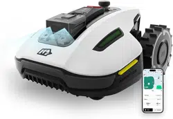
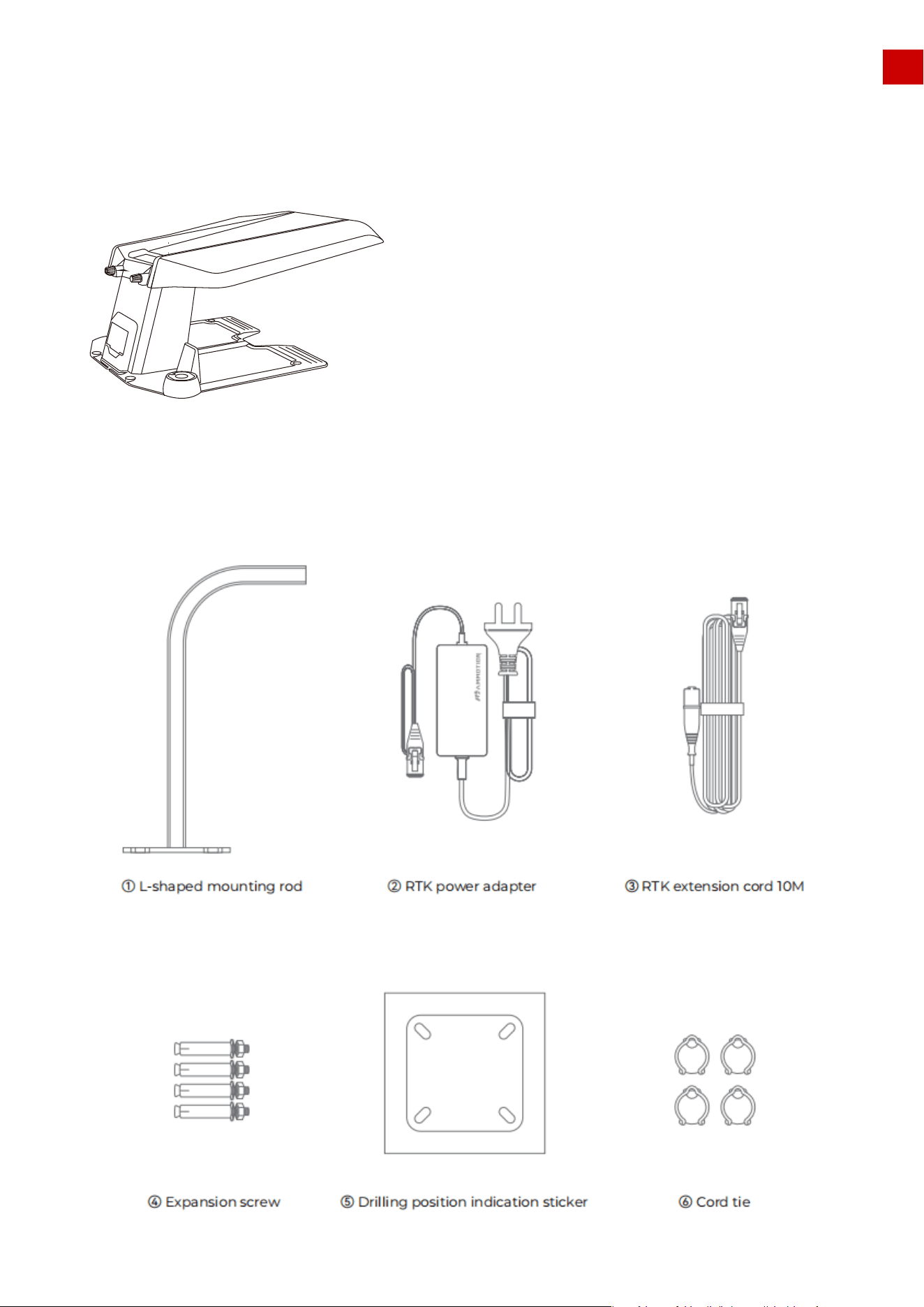
2.2 Box Contents:
MAMMOTION LUBA is a 4-wheels-drive (4WD) robotic lawn mower.
LUBA Series robot lawnmowers feature RTK GNSS navigation and virtual-mapping systems. Those allow users
to customize their mowing tasks with different mowing areas and schedules in the Mammotion APP. They
provide a picture-perfect lawn maintenance solution with a real hands-free experience.
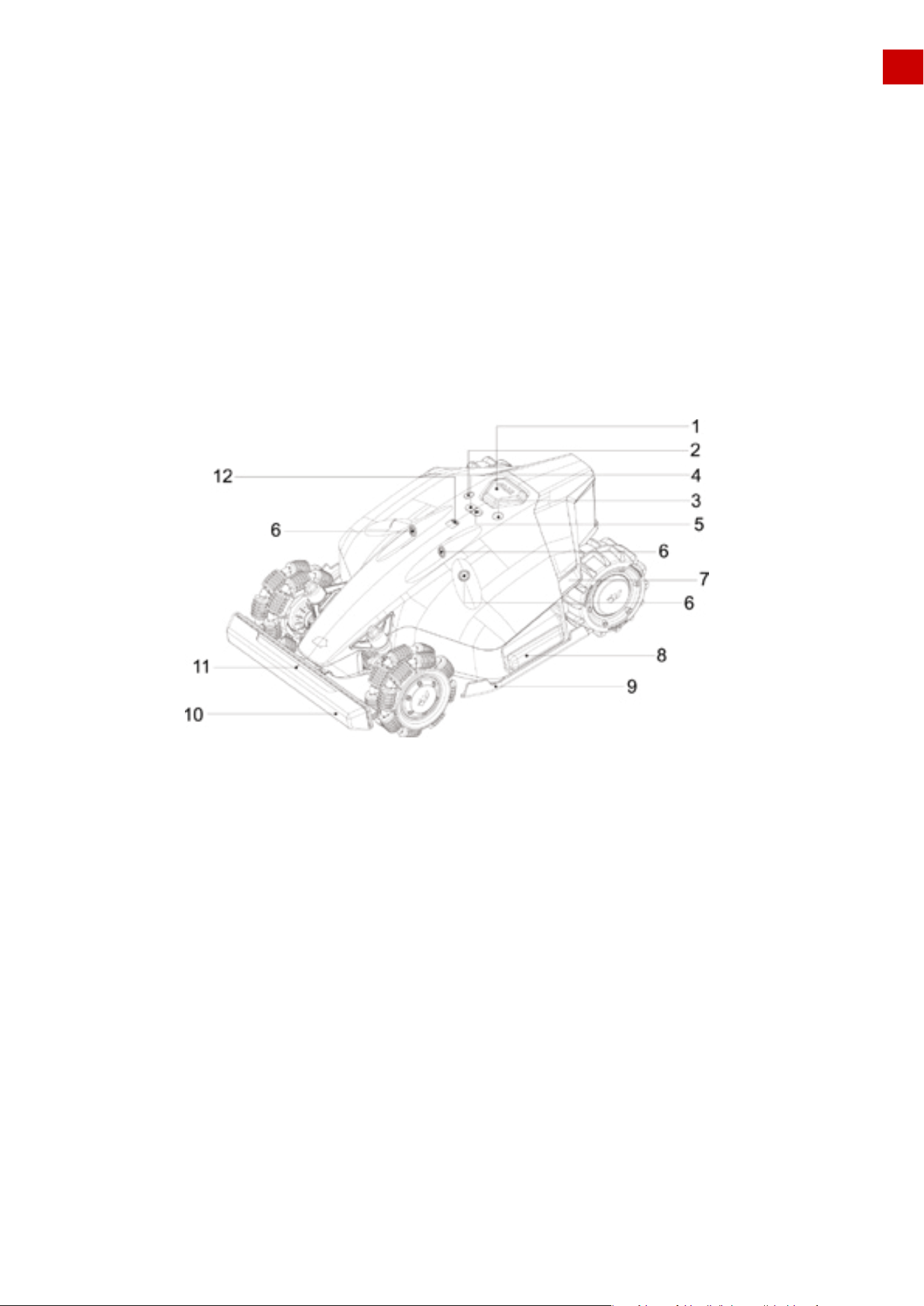
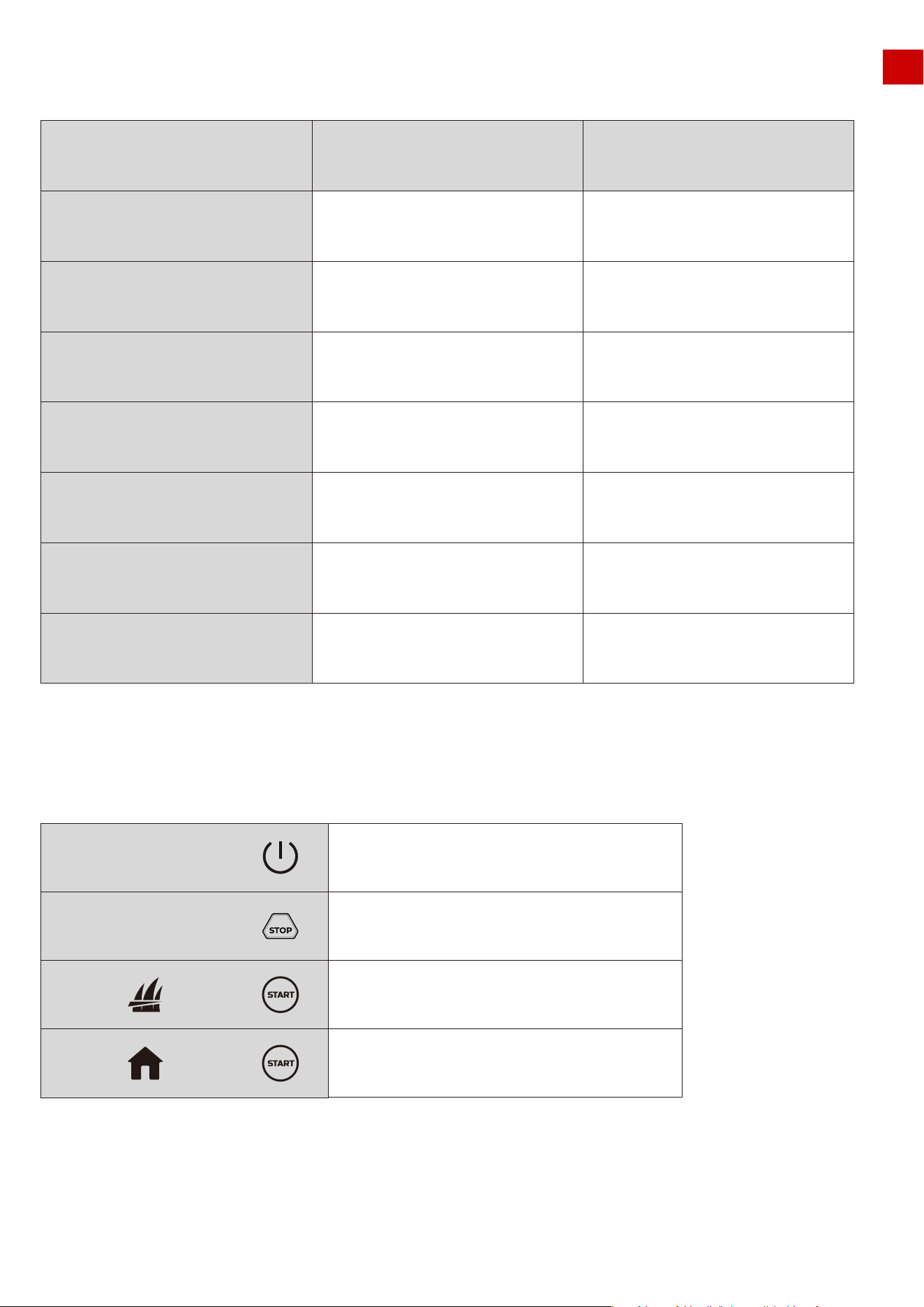
The numbers in the figure represent:
1.Emergency Stop button
2.Start button
3.Power button
4.Auto-return button
5.Continue work button
6.Ultrasonic sensor
1. The LED side lights are:
1) constantly red when working
2) pulsing flash, when charging & upgrading & sleeping
3) fast flash if there are any issues (with buzzing)
2. Switch on/off LUBA: long press Power button
3. Continue mission & Unlock LUBA: press Grass cutting button, then press Start button
4. Call back LUBA: press Auto return button, then press Start button
7.LED side light
8.Cushion
9.Protecting bracket
10.Front bumper
11.LED indicator on the front bumper
12.Rain sensor
EN
Note:
10
LUBA Robotic Mower Quick Reference Chart 1
LUBA Robotic Mower Quick Reference Chart 2
EN
Status
LUBA sleeping or "Pause"
on App clicked
Working (manual control and
automatic working)
Upgrading
LUBA with issue/defect
(contains hard ware/software issue)
Upgrading failed
STOP button triggered/get stuck
/extrication failed/lift sensor triggered
/slope out of threshold
Undirected/Position status not OK/
No satellite signal found
LED side light
Off
From local time 8:00-18:00 green on
from local time 18:00-8 00 off
user can manully switch it constant
on /off
Pulsing Red
Very fast red flash
Very fast red flash
Pulsing Red(once per second)
Pulsing Red(once per second)
LED indicator on the
front bumper
Green on
Green on
Green on
Green on
Green on
Green on
Green on
11
Long press (5s)
Press
Power on/off LUBA
Stop and lock LUBA
Unlock LUBA and continue work
Unlock LUBA and return
to charging station
First press then press
First press then press
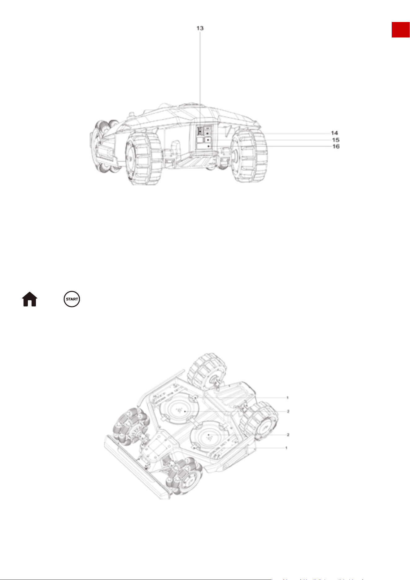
The numbers in the figure represent:
13.Secure key
14.USB port
15.Charging port on LUBA
16.Infrared receiver
EN
Note:
If in the returning home process, STOP is pressed and LUBA is locked, please First press
then to continue Auto-returning.
USB port is reserved for trouble shooting and debugging.
12
The numbers in the figure represent:
1. Cutting blade*8 2. Blade disk*2
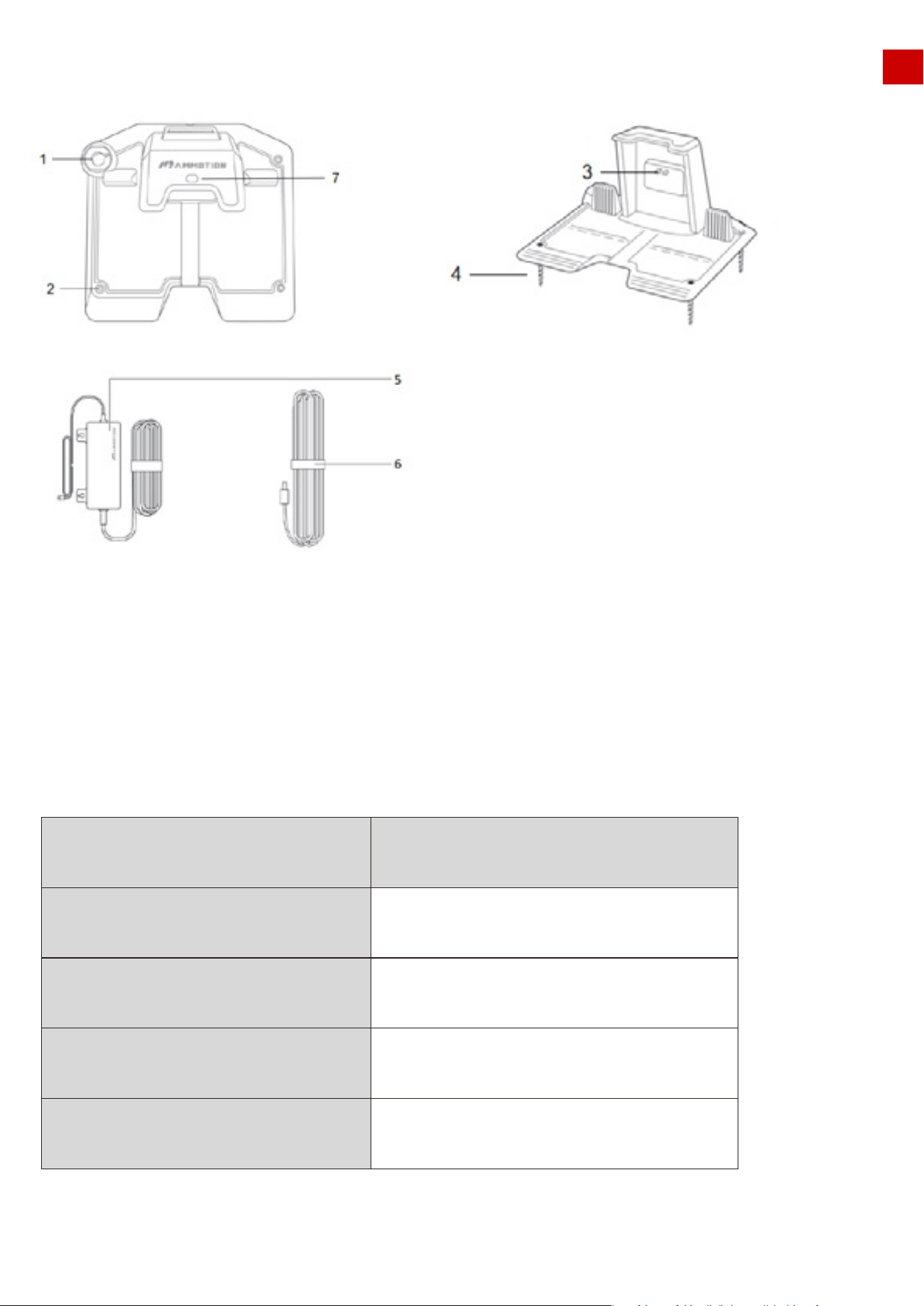
The numbers in the figure represent:
1.Mounting hole for RTK base pole
2.Mounting holes*3
3.Charging pin on charging station
4.Screws*3
5.Power adaptor
6.Extension wire(10meters)
7.LED light of charging station
EN
2.3 Charging Station Product Overview
Charging Station Quick Reference Chart
Status
Reference station initializing
(searching satellites)
Normal operation
Reference station defect & no
satellite signal for long time
LED on RTK reference station
green flash
from local time 8:00-18:00 green constant on from
local time 18:00-8:00 off
constant red on
Reference station upgrading blue flash
13
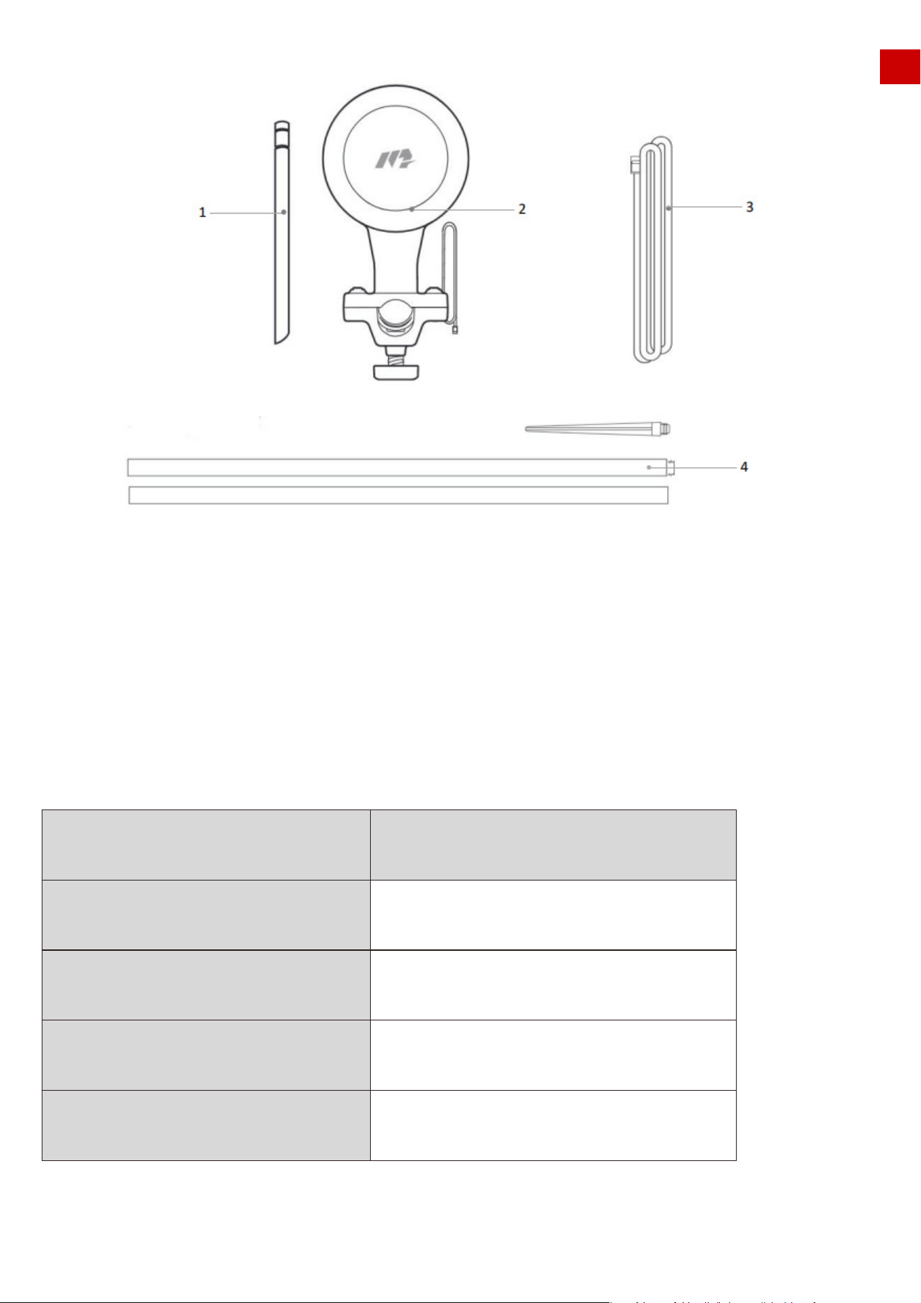
1.Radio Antenna
2.RTK Reference Station
3.Wire(2.5 meter or 8.2 feet)
4.Mounting pole
2.4 RTK Reference Station
Charging Station Quick Reference Chart
EN
Status
Reference station initializing
(searching satellites)
Work properly
Reference station defect & no
satellite signal for long time
LED on RTK reference station
green flash
from local time 8:00-18:00 green constant on from
local time 18:00-8:00 off
constant red on
Reference station upgrading blue flash
14
LUBA garage:
LUBA RTK reference station wall installation kit:
2.5 Other accessories
EN
15
About RTK:
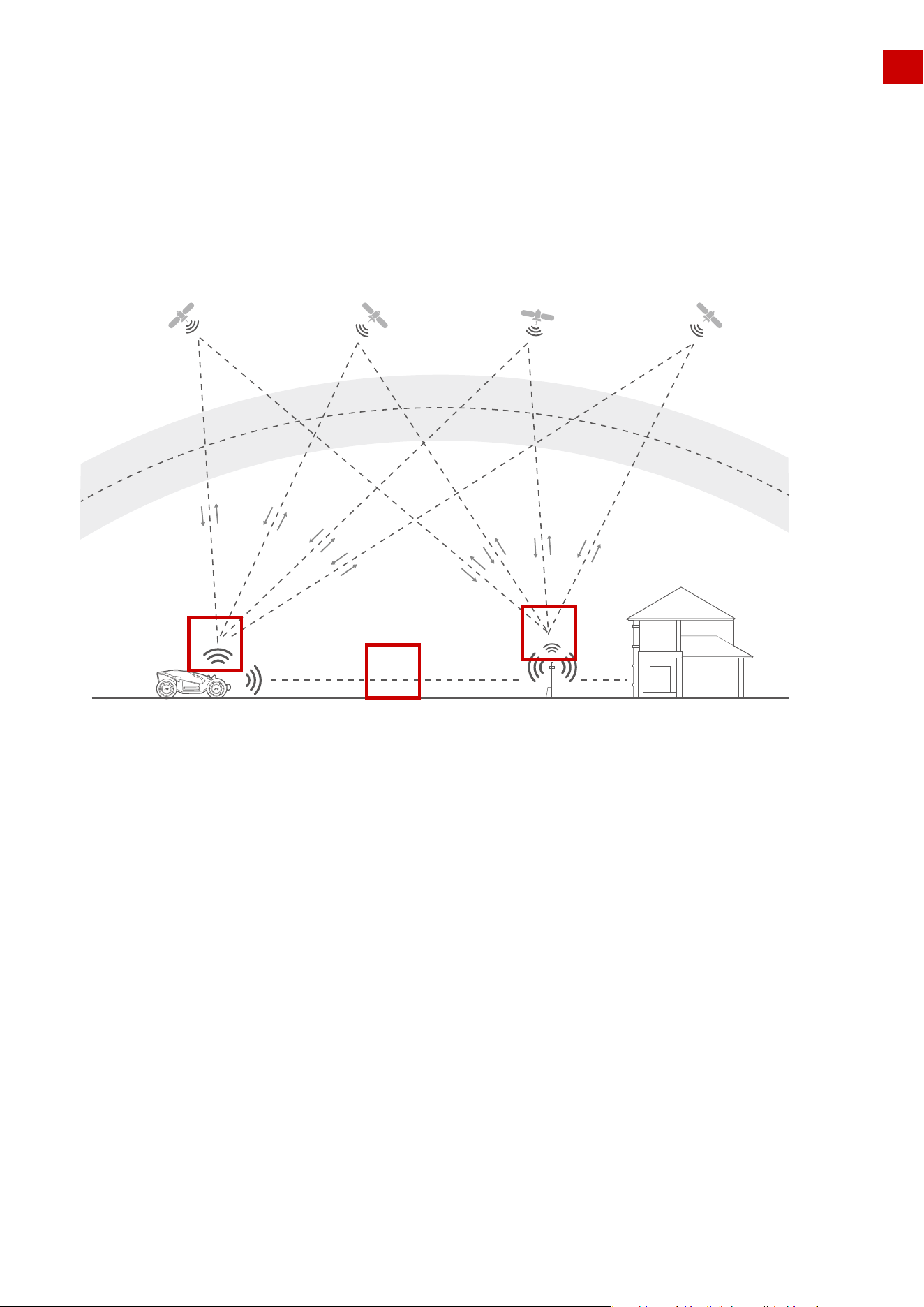
2.6 How LUBA’s positioning and dynamic system works:
EN
Mower BuildingRTK base&charging station
Satellite
LUBA uses RTK and Multi-Sensor Integrated Navigation System to navigate. RTK is a satellite naviga-
tion system that significantly improves device positioning to an accuracy of less than 5 cm (approx. 2
inches). With access to all 4 global navigation systems (GPS, GLONASS, BEIDOU, and Galileo) and
additional sensors, LUBA’s strong satellite signal provides nearly 100x greater accuracy than traditional
GPS systems. The advanced RTK system enables precise positioning for LUBA to within 5 cm (approx.2
inches) of accuracy, without the need to install cumbersome boundary and perimeter wires.
The RTK system of LUBA uses a full frequency multiple satellite-based system(GPS, BEIDOU, GLONASS and
Galileo), which improves the positioning accuracy to approximately 5 cm (approx.2 inches). However, the
accuracy crucially relies on the Global Navigation Satellite System(GNSS) signal. There are 3 things that can
determine the performance of LUBA’s positioning:
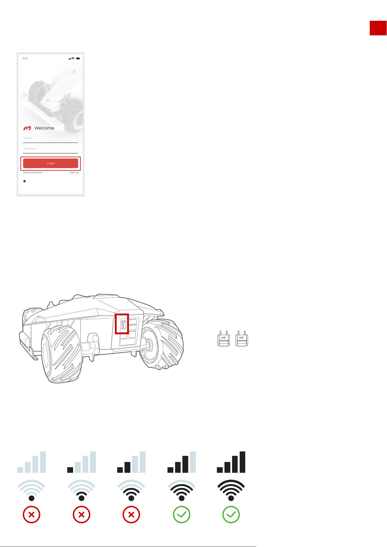
1.The RTK Reference Station must receive enough satellite signals from the satellites in the sky, which
means being positioned in a location where the signals from the sky are not obstructed,as “1” shown in
the image.
2.LUBA must also receive enough satellite signals from the satellites in the sky,which again means the
signals from the sky to LUBA are not obstructed,as “2” shown in the figure.
3.The data can be transmitted from RTK Reference Station to LUBA. As “3” shown in the figure. This
does not mean there should always be a line-of-sight view from each point of your lawn to the RTK
reference station. Our radio transmission ability allows the data transmission to also work as long as the
transmission path is not fully obstructed.
Ionosphere
Troposphere
2
3
1
16
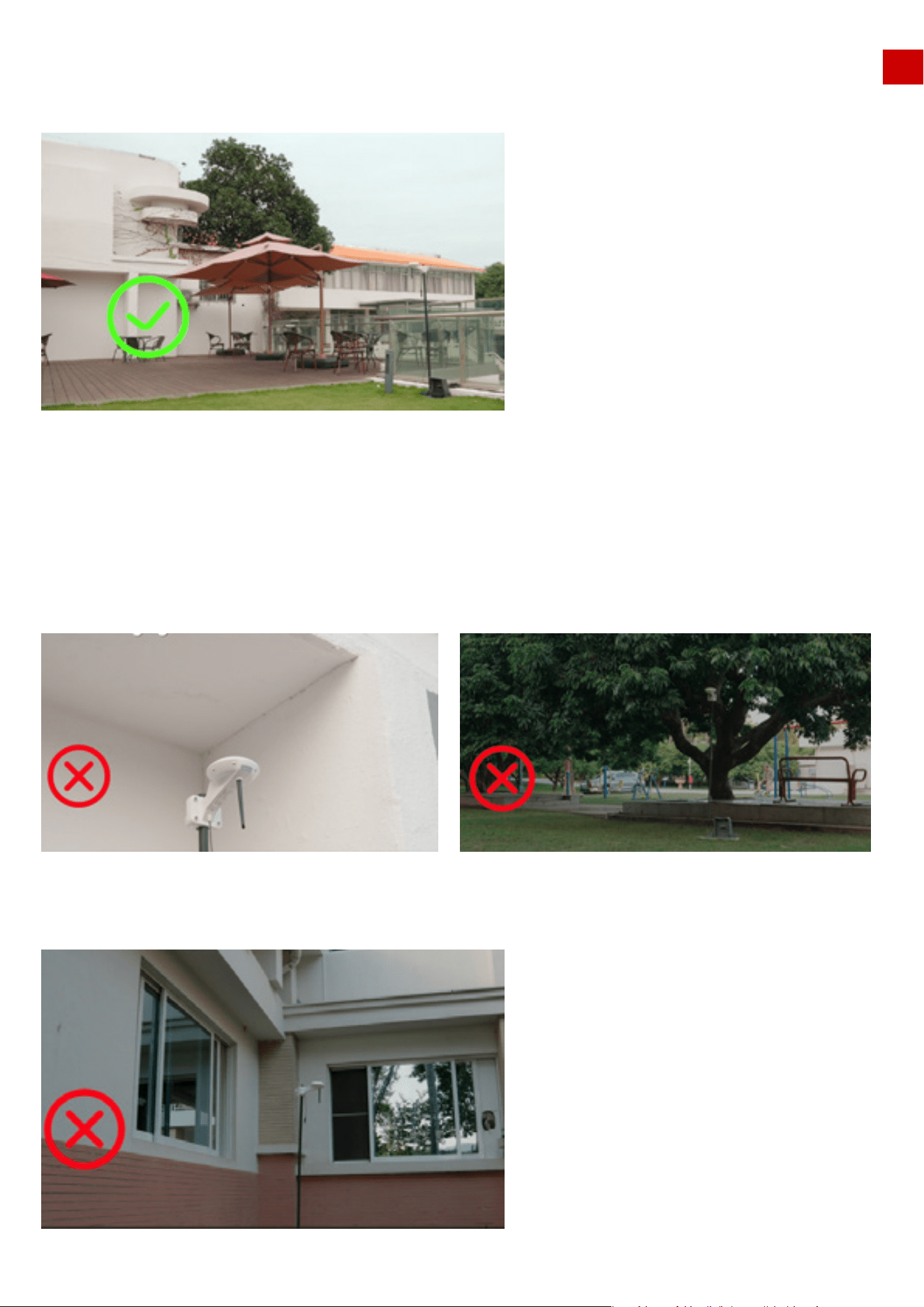
Factor 1: Satellite Signal to RTK Reference Station Blocked:
Factor 2: Satellite Signal to LUBA Blocked
In general, there are 3 factors that can weaken the performance of LUBA positioning
system:
EN
If there are any objects on or surrounding the antenna of the RTK reference station, charging station
and/or the mower, the signal will be weakened or blocked.
Solution:
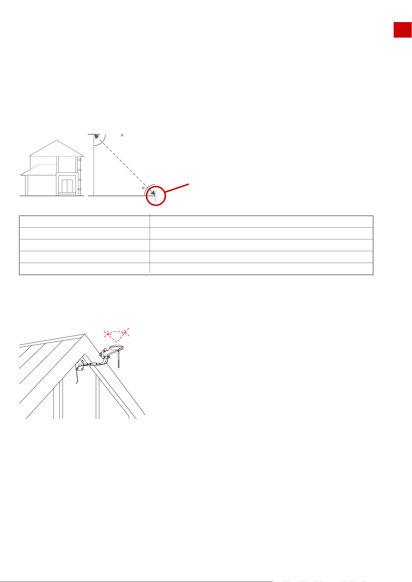
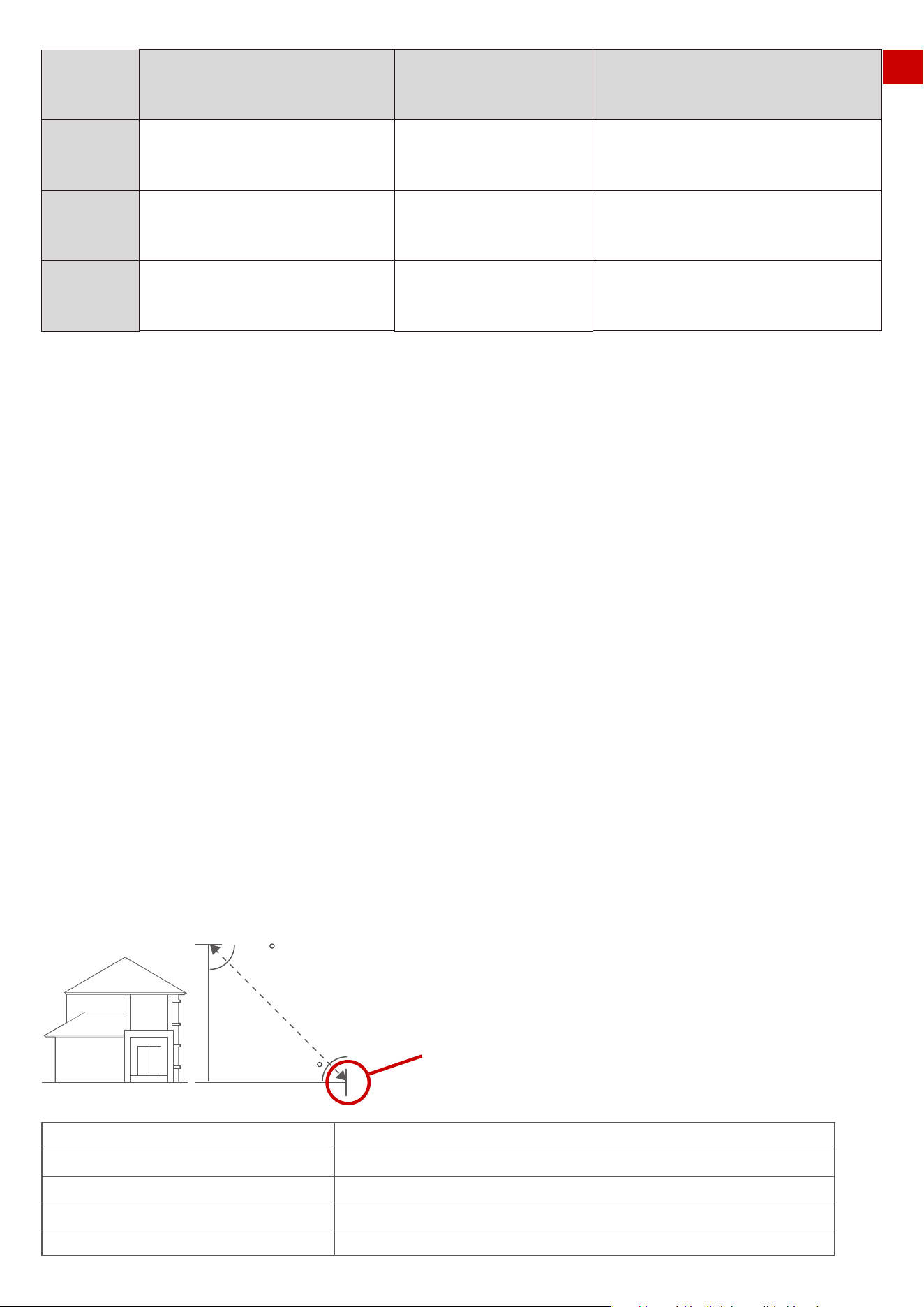
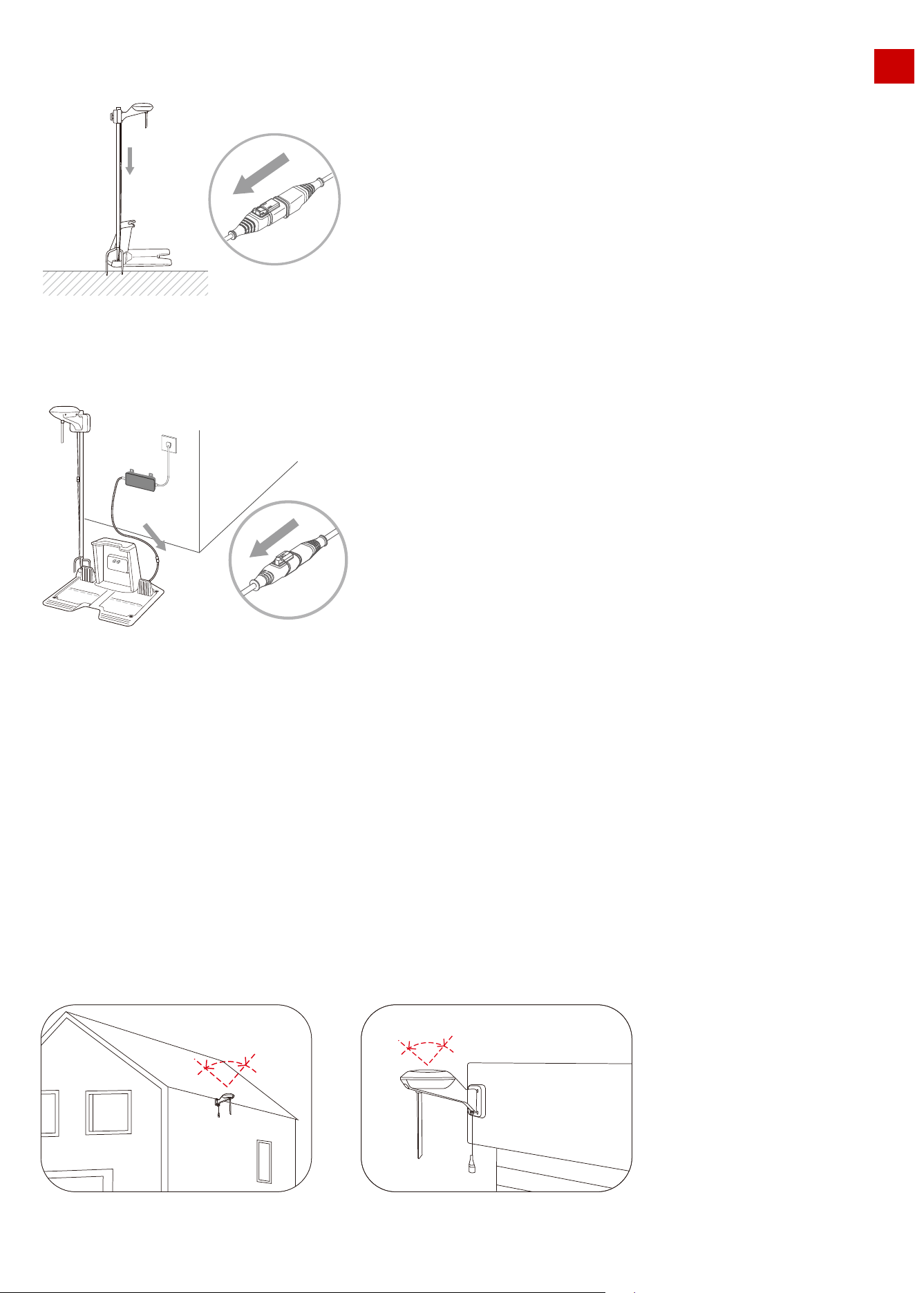
1.The distance between the RTK Reference Station and any obstacle (wall, roof, tree, etc.) ideally should
be at least the same as the height of the obstacle, as shown below.
2.Set the RTK Reference station on the wall or roof to give an open-sky area. As shown below.
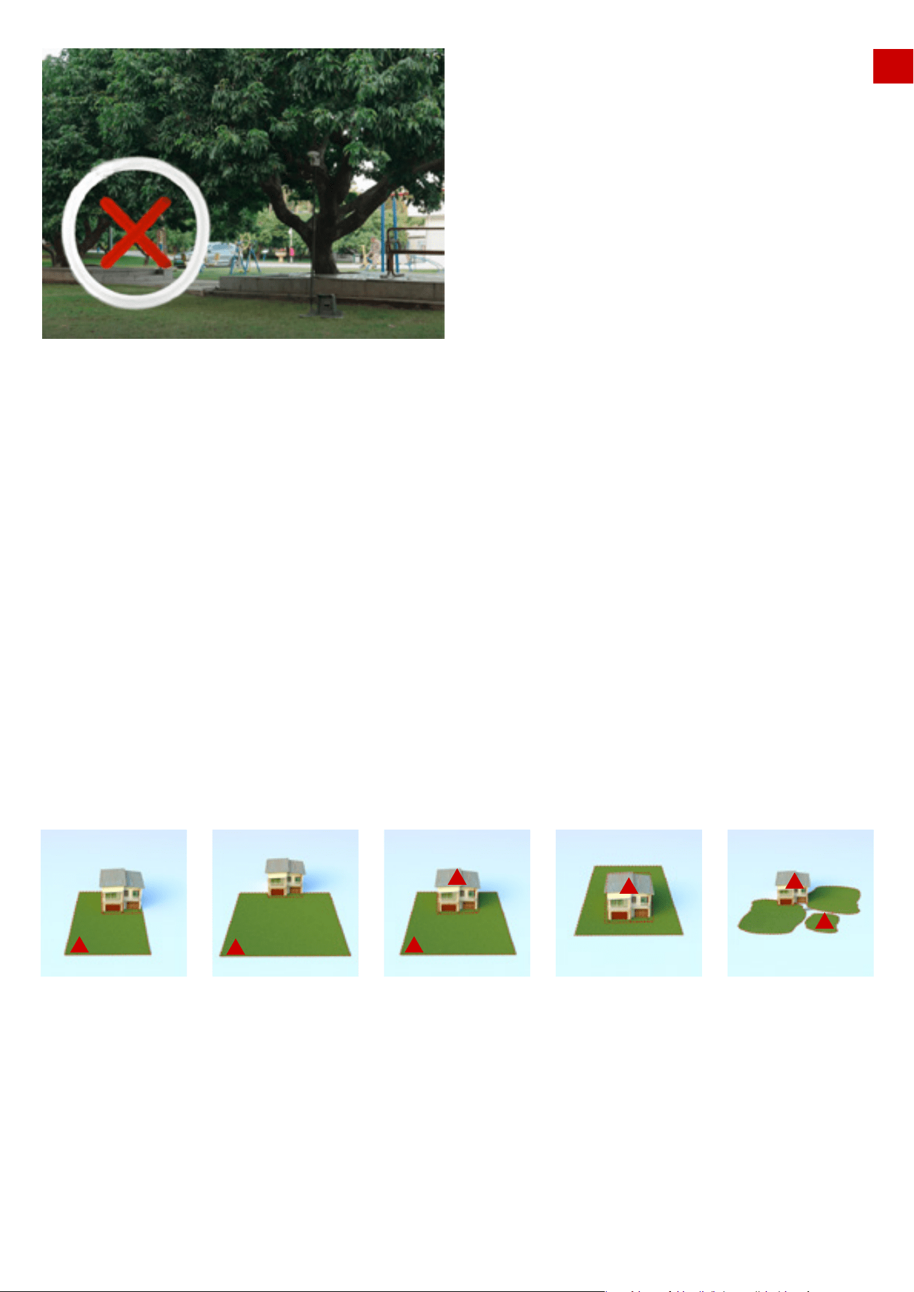
If LUBA itself is badly sheltered, the positioning system will also be weakened.
Solution:
1. We do not recommend you drive LUBA into a “U”-shaped or “L -shaped corner with high walls, under
large trees or under large eaves, each of which will strongly weaken the satellite signal received by LUBA
from the sky. We advise that you try to keep these parts out of the task area or place them in a no go zone.
2.If these corners or high walls exist in your lawn, please keep LUBA at least 15 cm (approx. 6 inches) away
from them.
45
45
Height of the building or obstacle Distance between the RTK base and the building or obstacle
1m
2m
3m
4m
>1m
>2m
>3m
>4m
RTK base & charging station
≥ 90︒
17
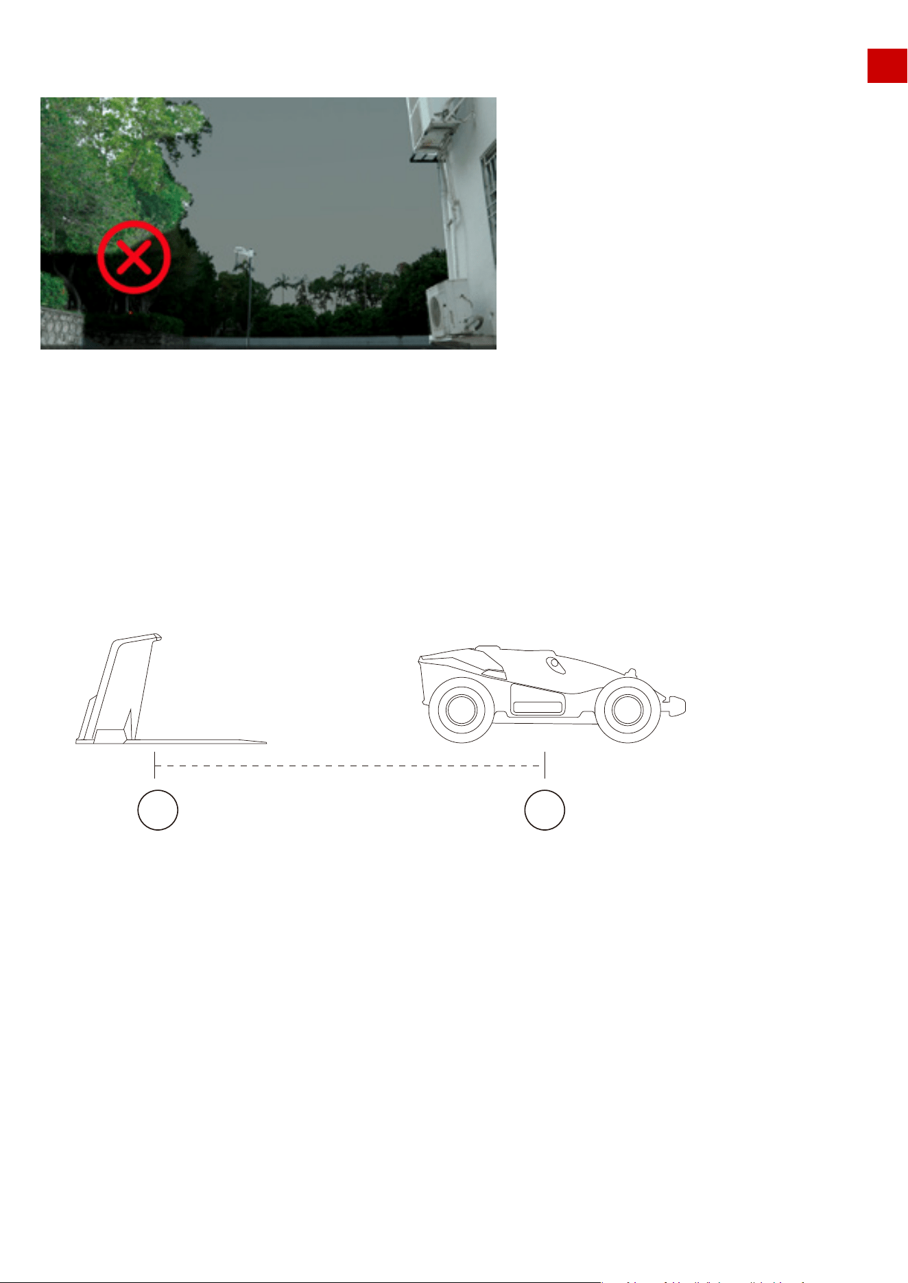
Factor 3: Transmission Path Blocking
EN
If the transmission path for radio signals from the RTK Reference Station to LUBA is fully obstructed by large
metal or concrete walls, LUBA will could not receive the data from the RTK Reference station and so will not
be able to position with cm level accuracy.
Solution:
1.The communication transmission power gets weakened with long distance. Please make sure that the
distance between the boundary of the map and the reference station is less than 80 m (262 ft).
2.Make sure that at the initialization, when LUBA is at the charging station position you set, the positioning
status is “fine” (this will be auto-checked when initializing)
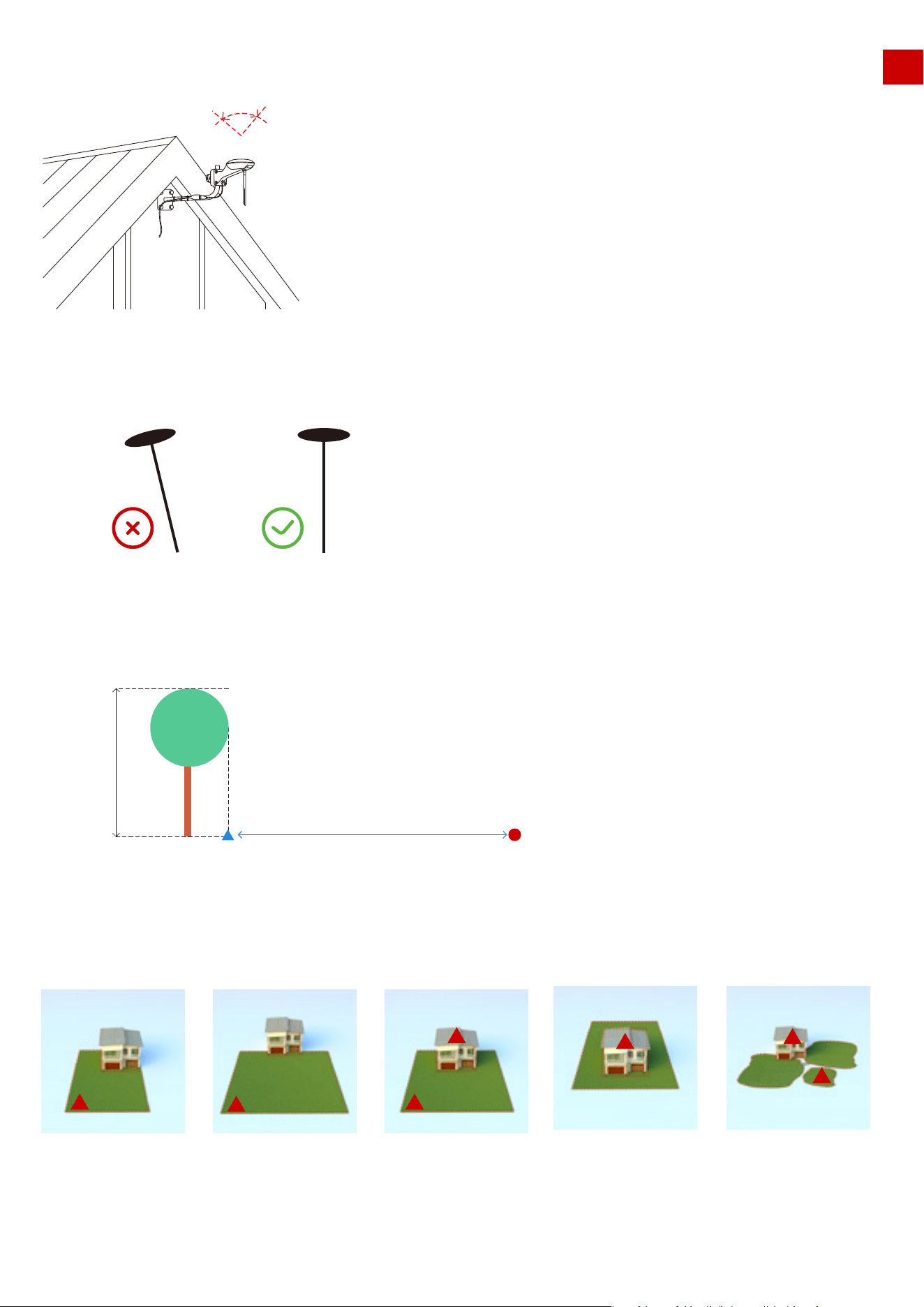
3.The figure below shows recommended positions for the RTK Reference Station, indicated by the red
triangle.If your lawn is “O”-shaped, “U” shaped, or you have multiple lawns, we recommend you set the RTK
Reference Station at a higher point, such as on the roof. This can be done using the wall installation kit. If
your lawn is “L”-shaped, you can set the reference station either on the roof or at the corner point as shown
below.
But does this mean there are too many limitations for LUBA to be useful? This is not the case, and on our
website you can find many examples of set-ups, videos and recommendations to assist you in determining
if your lawn is suitable for LUBA, and how to set up LUBA to work efficiently.
Also, the Mammotion App and LUBA system will automatically check the positioning quality, and check if
the initialization and task setting is OK or not. If not, the App will provide information on how to modify the
your settings to let LUBA work properly.
L-shape On one side U-shape O-shape Multiple lawns
18
About Multi-Sensor Integrated Navigation System:
EN
In addition to using satellites, LUBA’s Multi-Sensor Integrated Navigation System also enhances the reliabili-
ty and robustness of LUBA’s positioning status. This system comprises an Inertial Measurement Unit (IMU),
odometer, and other ultrasonic sensors. This means that even in partly sheltered areas, thanks to this strong
additional positioning algorithm, LUBA can work properly.
About Auto-Recharging:
The auto recharging system of LUBA contains 2 parts; one is integrated navigation system, the other is the
infrared sensor.
During initialization of LUBA, the position of the charging station is set in the local navigation system. As
shown below, LUBA is at the charging station, and the position of the charging station is indicated the map,
The area shown with blue lines is defined as the “recharging area”, which means that in this area LUBA can
move to dock with the charging station and perform auto recharging by means of the infrared sensor in this
area only, no integrated navigation system will be used.
However, if LUBA is outside this area, in order to auto -recharge LUBA needs to :
First, go back from its current place to the “recharging area” via the predefined map (task area and connec-
tion path) and integrated navigation system.
Second, return to the charging station itself, guided by the infrared sensor.
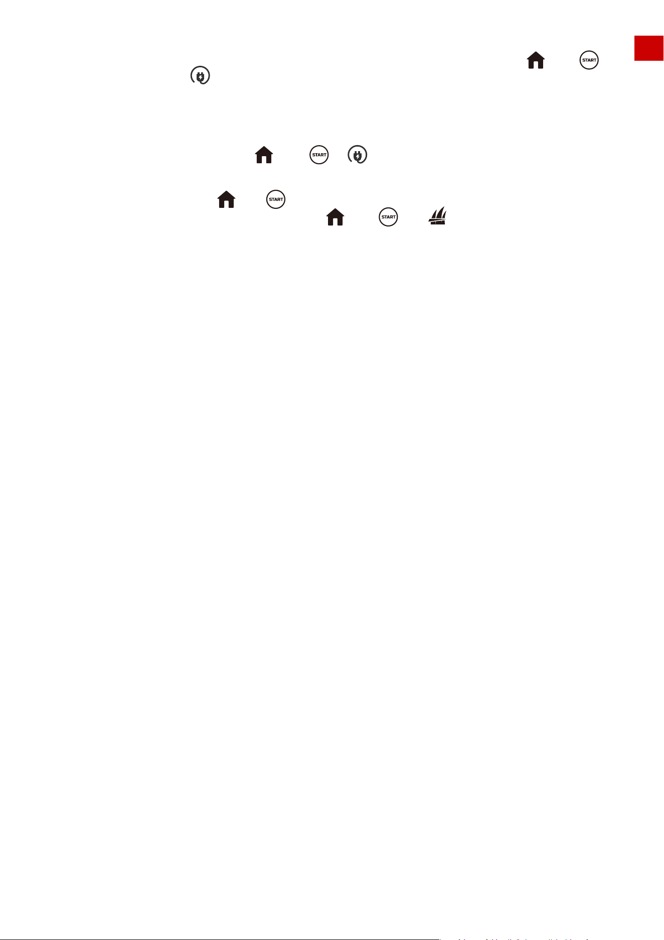
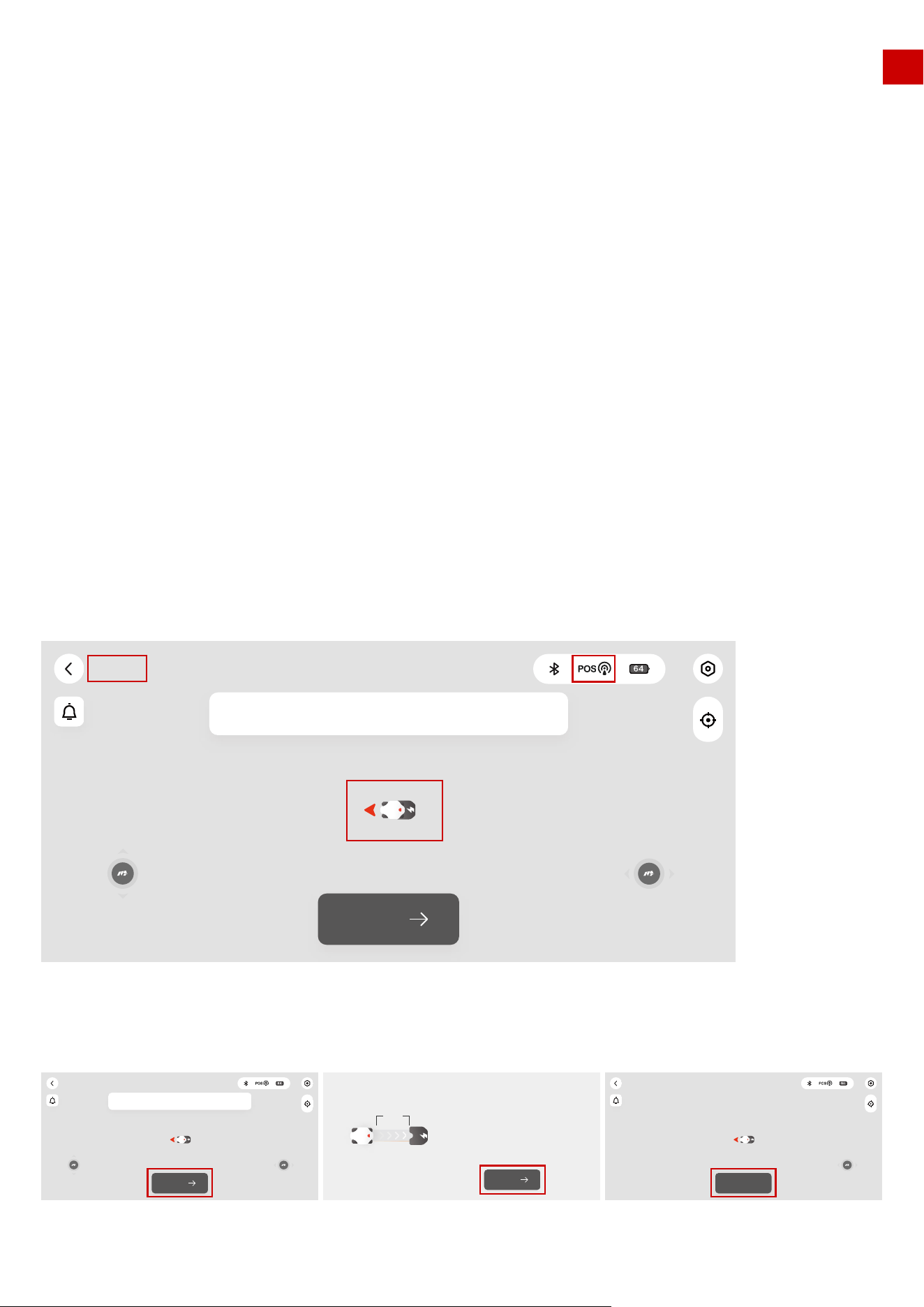
So, to set LUBA on the charging station to recharge, there are 3 methods:
1.Manually move LUBA to the charging station, with the rear of LUBA facing the charging station and the
charging port on LUBA properly set to align with the pins on the charging station
2.Put/drive LUBA about 1.5-2 m (5-6.5 ft) in front of the charging station, with the rear of LUBA facing the
charging station. Press the power button of LUBA to power LUBA on. Next press then press
to direct LUBA back to the charging station. As the infrared sensor system is used, you can still do this even
in indoor areas where there is no satellite signal and LUBA cannot do the navigation.
19
Ready! (Luba-MATJTT6F)
Create
Please click the button to start planning task area
EN
About Perception:
The perception system of LUBA contains 2 parts: 4 ultrasonic sensors and the front
bumper. These are used to avoid obstacles in the mowing path.
3.If a task area is already set and is connected to the charging station by a connection path or if the
“recharging area” is immediately next to the task area, you can call back LUBA by pressing then
on the mower or by pressing on the App. LUBA will itself then find the right way itself to first return to
the charging area and align the rear of the mower to face the charging station. It will then back into the
charging station and do the recharge automatically.
If LUBA is not in the task area or on the connection path, you first need to first drive LUBA into the task area
or onto the connection path. Then press then or on App.
Alternatively, you can manually drive LUBA to the “recharging area” (about 1.5-2 m or 5-6.5 ft in front of the
charging station), and then press then . Note that if while doing the recharging process, LUBA is
blocked or “STOP” is triggered, it is necessary to press then , not .
Perception logic/ Bypass strategy:
All the perception logic is for the obstacles that are not defined as part of a “no go zone”. If the area of obsta-
cle is predefined as a “no go zone”, the cutting route will not contain this area. Adding permanent obstacles
to defined “no go zone” is more friendly for lawn care as the cutting route is then pre-planned to avoid them
and i recommended.
The following modes can be selected:
Off: The ultrasonic sensors are switched off when in this mode, and only the front bumper is active to detect
collisions. If the front bumper is triggered by a collision, LUBA will go backwards for about 10 cm (approx. 4
inches), then turn and bypass the obstacle.
This mode should only be used in areas where the grass is shorter than 15 cm (approx. 6 inches). Grass taller
than this can lead to very frequent triggering of the ultrasonic sensors, which would then result in LUBA
taking frequent evasive actions.
Level 1: In this mode, when the ultrasonic sensors detect something, LUBA will slow down to about 0.05 m/s (2
inch/sec) and continue moving forwards and cutting. Once the front bumper is triggered, LUBA will go
backwards for about 10 cm (approx. 4 inches), then turn and bypass the obstacle.
The ultrasonic sensors, when triggered, are therefore used to minimize the impact speed of LUBA by slowing
it down. Should a genuine obstacle be present, the front bumper will be gently triggered and is therefore
used to determine whether the “obstacle” really exists. If the “obstacle” is just a patch of high grass, the front
bumper will not be triggered and LUBA will continue working.
This mode is quite useful for lawns that have regions of high grass and/or grass is not that smooth.
Level 2: In this mode, when the ultrasonic sensors detect something, LUBA will go backwards for about 10
cm (approx. 4 inches), then turn and bypass the obstacle.
The advantage of this mode is that LUBA does not touch the obstacle and will turn around once something is
detected. The disadvantage is that even very small regions of grass higher than 7 cm (approx. 2.75 inches)
have the potential to be detected and recognized as an “obstacle” and as a result that small region will not be
cut because LUBA will bypass it.
This mode is quite useful for flat lawns with grass mainly lower than 7 cm (approx. 2.75 inches).
20
EN
Note:
General preparations
3.1 Find a Good Spot to install RTK Reference Station
1.Read and understand the safety chapter before you install the product.
2.Use original spare parts and installation material.
1.Water filled holes in the lawn can cause damage to the product.
2.Sketch the layout of your house and lawn and take note of any obstacles. This makes it easier to examine
where to put the charging station, the reference station, and set up the virtual boundaries.
3.Decide where to install the charging station, the RTK reference station, the transport paths and the virtual
boundaries for the work areas and no-go zones.
4.Fill in any large holes in the lawn.
As shown in chapter 2.2 “About RTK”, the RTK Reference Station should be set in a suitable place:
1.The distance between the RTK Reference Station and any walls, roofs, and trees should be ideally at least the
same as the height of the wall / roof / tree, as shown below.
Perception
mode
Off
Level 1
Level 2
Ultrasonic sensors
OFF
Slow down LUBA
Once detect something,LUBA will
go backwards, then turn and bypass
the obstacle
Once triggered, LUBA will
go backwards,then turn
and bypass the obstacle
The same as level 0
The same as level 0
Front bumper
Should be only used in areas where the
grass is nearly all high higher than 15cm
which can lead to nearly constant disturb
to ultrasonic sensors
Useful for lawn, which is partly with high
grass and the grass is not that smoot
Useful for flat lawn with grass mainly
lower than 7cm
Area of application
3. LUBA quick start Installation
45
45
Height of the building or obstacle Distance between the RTK base and the building or obstacle
1m
2m
3m
4m
>1m
>2m
>3m
>4m
RTK base & charging station
21
EN
2.Ensure that the RTK reference station is at least 5 m (approx. 16.5 feet) away from any large glass walls or
large metal objects, such as a wall made of iron sheet.
3.The RTK Reference station should be oriented vertically. As shown below.
4.If there are tall trees with large crowns, you should set the RTK reference station in the lawn as shown
below. The distance to the reference station should be at least the same as the height of the tree to the edge
of the crown.
5.If your lawn is an “O”-shape, “U” shape, or if there are multiple lawns, we recommend you set the RTK refer-
ence station in a higher place, such as on the roof. If your lawn has an “L”-shape, you can set the reference
station on the roof or at the end of the lawn as shown below.
If your Lawn is an “O”-shape, “U” shape , or you have separate lawns, we recommend that you to set the RTK
reference station at a high point on a wall or a roof, using the with wall installation kit that is available as an
accessory.
Alternatively, set the RTK Reference station on a wall or roof that has an open-sky view. As shown below.
≥ 90︒
H
Edge of tree’s crown Here set RTK reference station
H
L-shape On one side U-shape
O-shape Multiple lawns
22
EN
Correct RTK reference station settings:
1. Open-sky area on the lawn, at least 3 m (approx. 10 feet) from the wall.
Wrong RTK reference station settings:
1. Under a roof or trees
2. Set on the roof or high on a wall with open-sky area (typically for lawns with “O”-shape, “U” shape, or
with separate lawns).
3. Away from metal or glass walls
2. Very close to the wall
3. At an “L” shaped corner
23
EN
As shown in chapter 2.2 “About Auto-Recharging”, the charging station should be set in a place where:
5.Totally separate from the lawn
6.Too far away (more than 80 m or 262 ft) from the edge of lawn
1. The charging station (A) is near the docking point (B) and has an open-sky view. This means that
90°of the sky in all directions must be unblocked. The charging station docking point (B) is 2 m or 6.5 ft.
in front of the charging station.
2. No obstacle or other items should be between A and B
3. When set on the ground, the charging plate must not be bent or tilted, or with grass taller than 5 cm
(approx. 2 inches) below the charging plate. Both the area of charging station and the “recharging area”
should be on flat ground. After LUBA is positioned on the charging station, the plate should not be bent.
4. in the middle of multiple obstacles (such as two walls, a wall and a tree etc.)
3.2 Find a Good Place to set Charging Station
24
A B2m
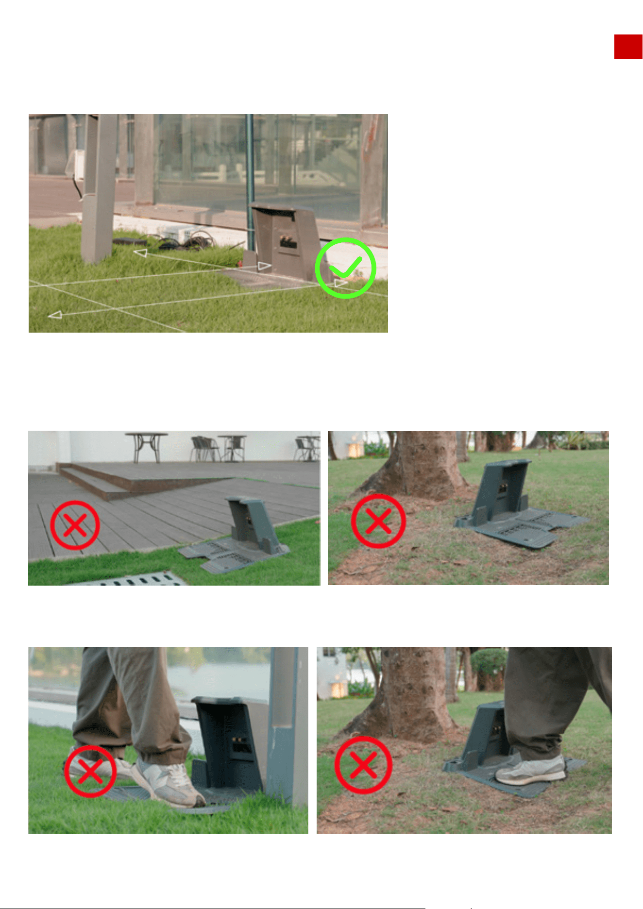
Correct charging station settings:
The place to set charging station should be flat and solid, also the “recharging area” (about 2 m or 6.5 ft in
front of the charging station) should also be flat and solid. The grass should be short.
EN
Wrong charging station settings:
1.Setting charging station on a slope
2.Thick grass which causes the charging station to bend when a heavy object, such as LUBA, is on it.
25
Flat Ground
EN
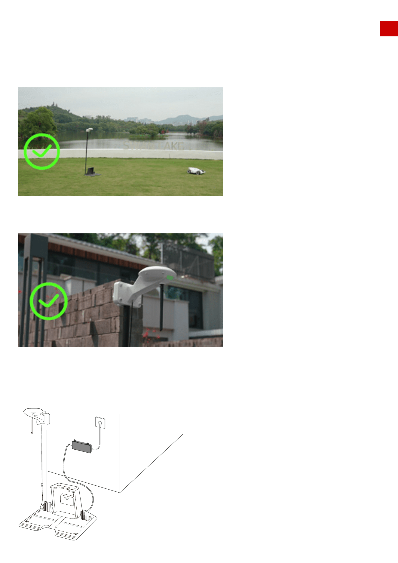
3.3 The RTK base is installed on the charging station
If the reference station is set on the charging station, the settings should be as follows:
Correct settings:
1. Open sky area.
2. One side beside a wall. Only one direction is obscured by the wall, other directions are totally free
Overview of the installation when it’s completed:
26
EN
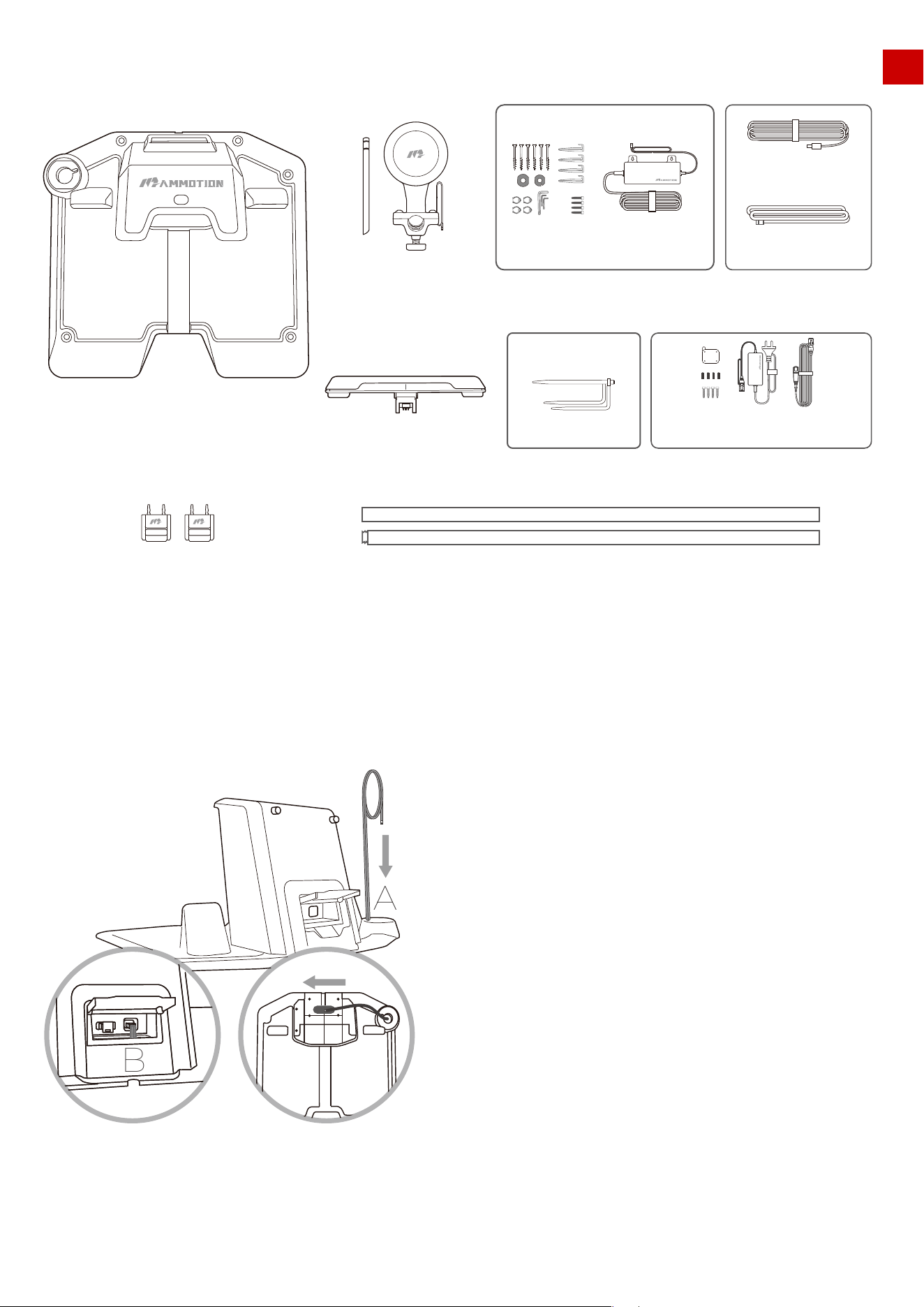
Installation Kit:
Installation Process:
1. Put the 2 m (approx. 6.5 feet) RTK extension cord from point A to point B, then install the line connector
at the interface B behind the charging station.
RTK Reference Station
Mounting pole
Bumper Accessory Kit C
Accessory Kit A
Power Supply Installation Kits
Accessory Kit B
Key
Charging Station
Trident Ground Stake
RTK reference station
connect cable(2m)
Charging station
extension cable(10m)
B
A
27
RTK Wall Mount Accessory Kit:
RTK reference station power supply
RTK reference station extension cable(10m)
EN
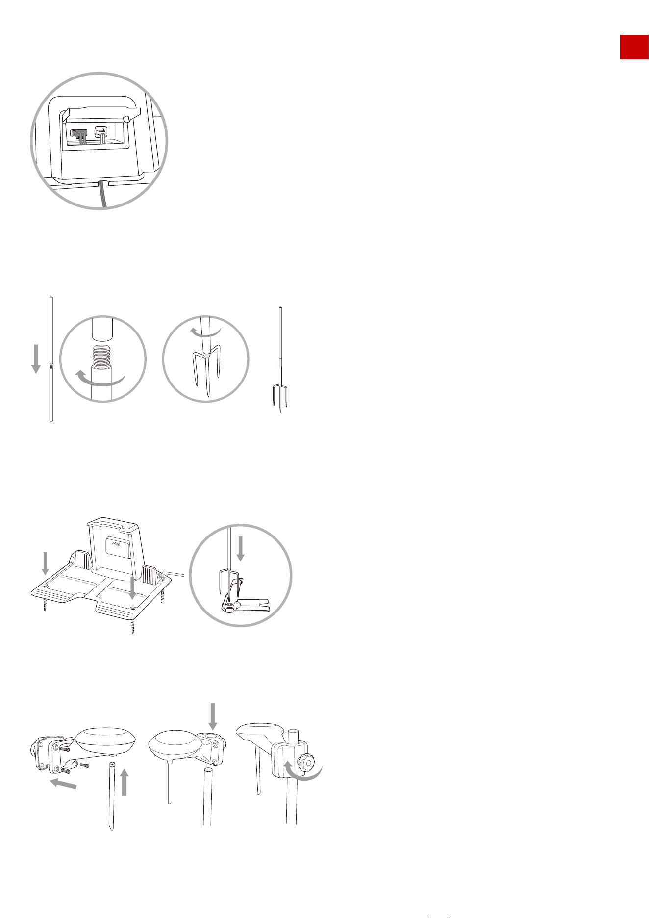
2. Screw the 10 m (approx. 33 feet) power supply extension cord into the interface C of the charging station.
3. As shown in the figure, screw the two metal rods together, and then screw on the trident ground stake.
4. Fix the charging station on a flat solid ground with the fixing screws. Insert and fix the trident ground
stake as shown in the figure and keep the metal rod upright.
5. Install the RTK antenna with four screws on the metal pole. The height of RTK antenna can be adjusted
as shown in the figure.
C
28
EN
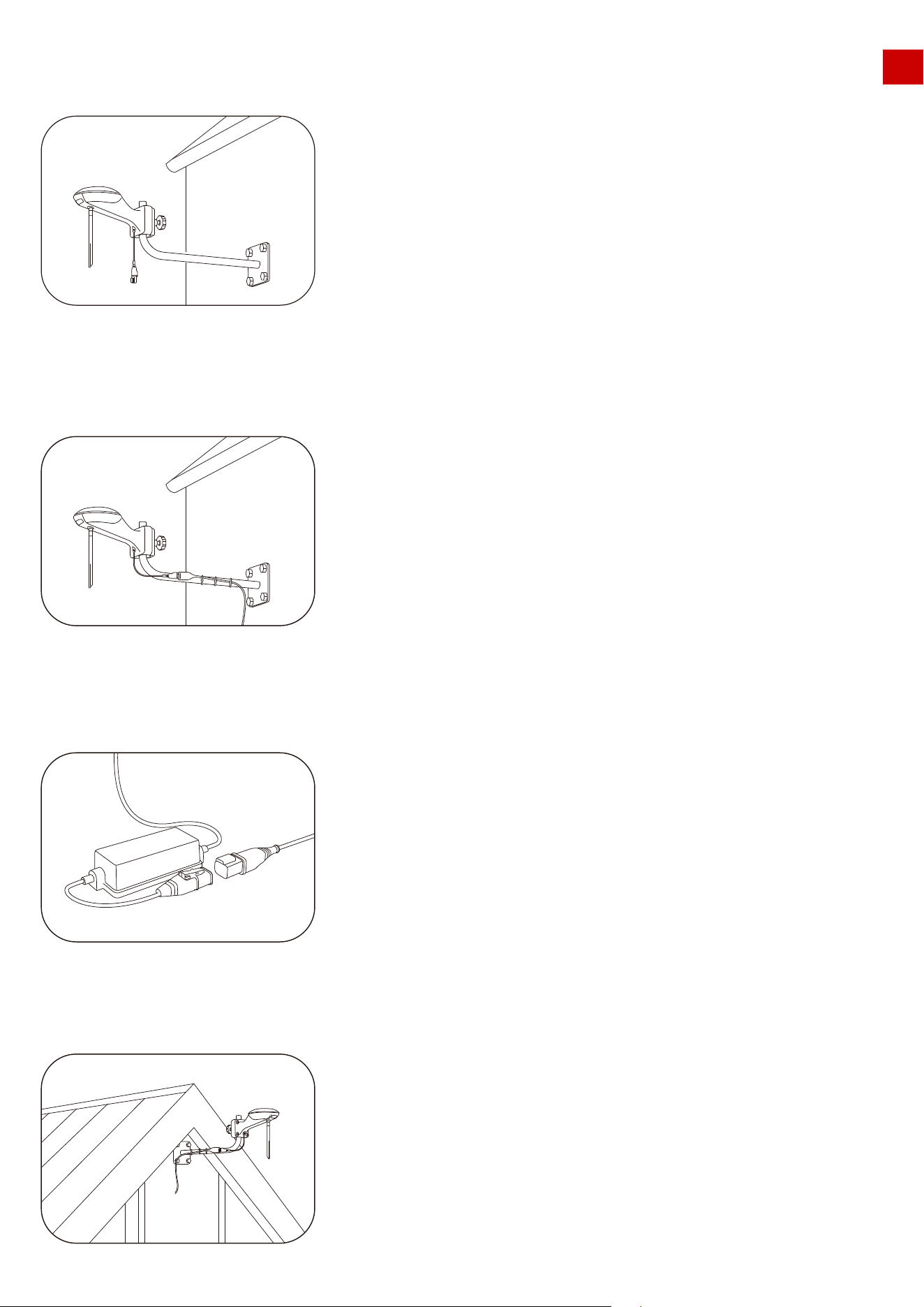
3.4 RTK reference station is installed separately from the charging station &
on the roof/wall
Correct settings:
6. Connect the 2 m (approx. 6.5 feet) RTK extension cord to the RTK antenna reference station cable.
7. Connect the 10 m (approx. 33 feet) power supply extension cord with power plug and insert the power plug
into an electrical outlet.
It is also possible to site the RTK reference station in a separate location to the charging station.
8. Check if the LED on the charging station is green. If it turns green, then this indicates correct opera-
tion. If it turns red, please pull out the power plug and repeat.
9. Check the LED on the RTK antenna. It should be flashing green, please wait until the LED on the RTK
antenna is constant green (this will take several minutes).
≥ 90︒
≥ 90︒
29
1. Choose a suitable installation area at a high place of your house.
2. Stick the sticker on the wall indicating the position of the drilling holes and drill the holes(8mm) at the
appropriate position.
EN
Wrong settings:
Overview of the installation when it’s completed.
RTK Wall Mount Kit:
Installation Process:
RTK reference station
power supply
RTK reference station
extension cable(10m)
RTK Wall Mount
Accessory
30
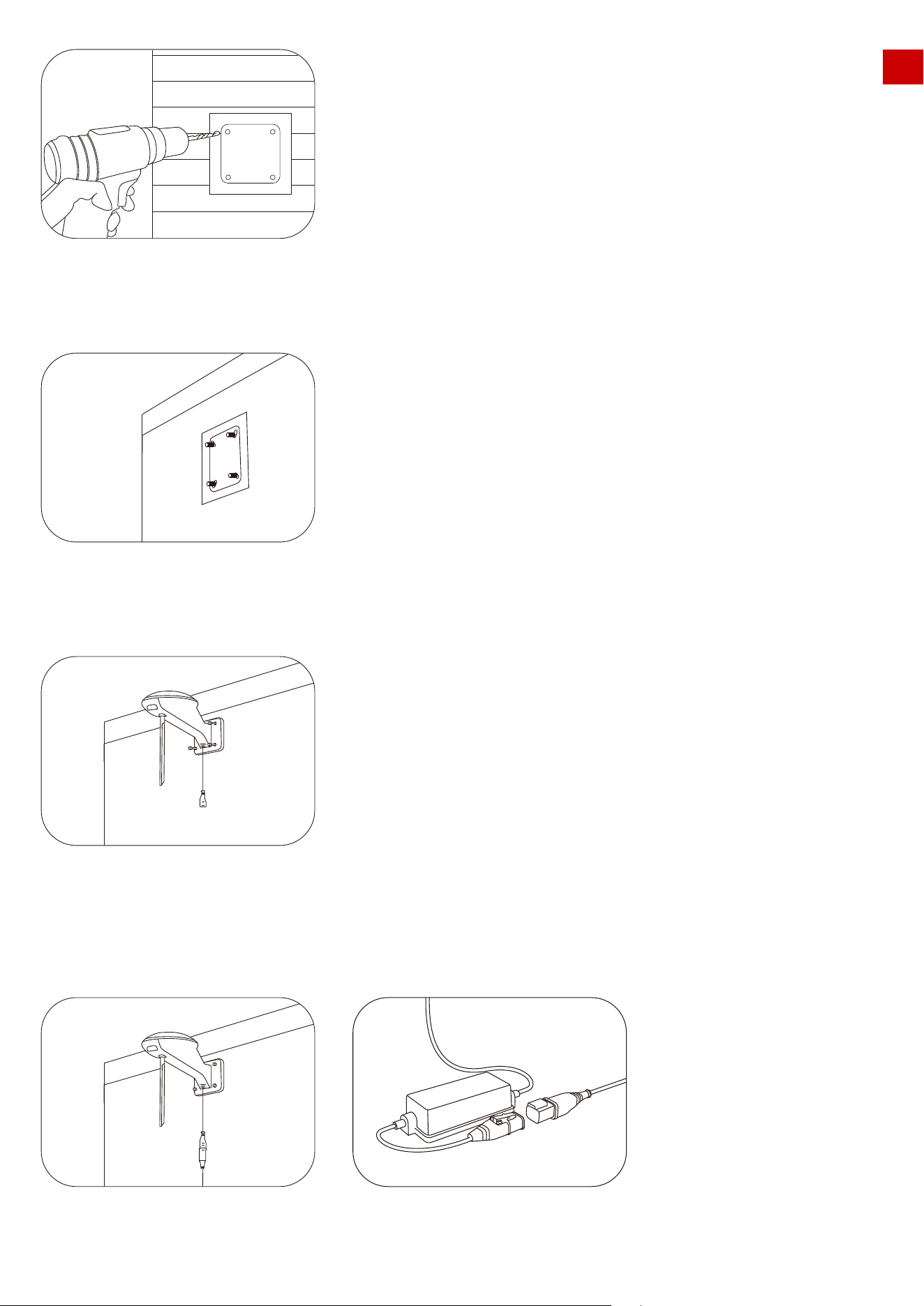
3.Install the expansion screws in the drilled holes.
4.Fix the RTK Reference Station on the sticker and tighten the screws.
EN
5.Connect the end of the RTK Reference Station extension cable (10m) to the RTK reference station and
connect the other end of the RTK Reference Station extension cable (10m) to the RTK power supply and turn
on the power.
31
6.The installation is complete.
It is also possible to site the RTK reference station in a separate location to the charging
station.
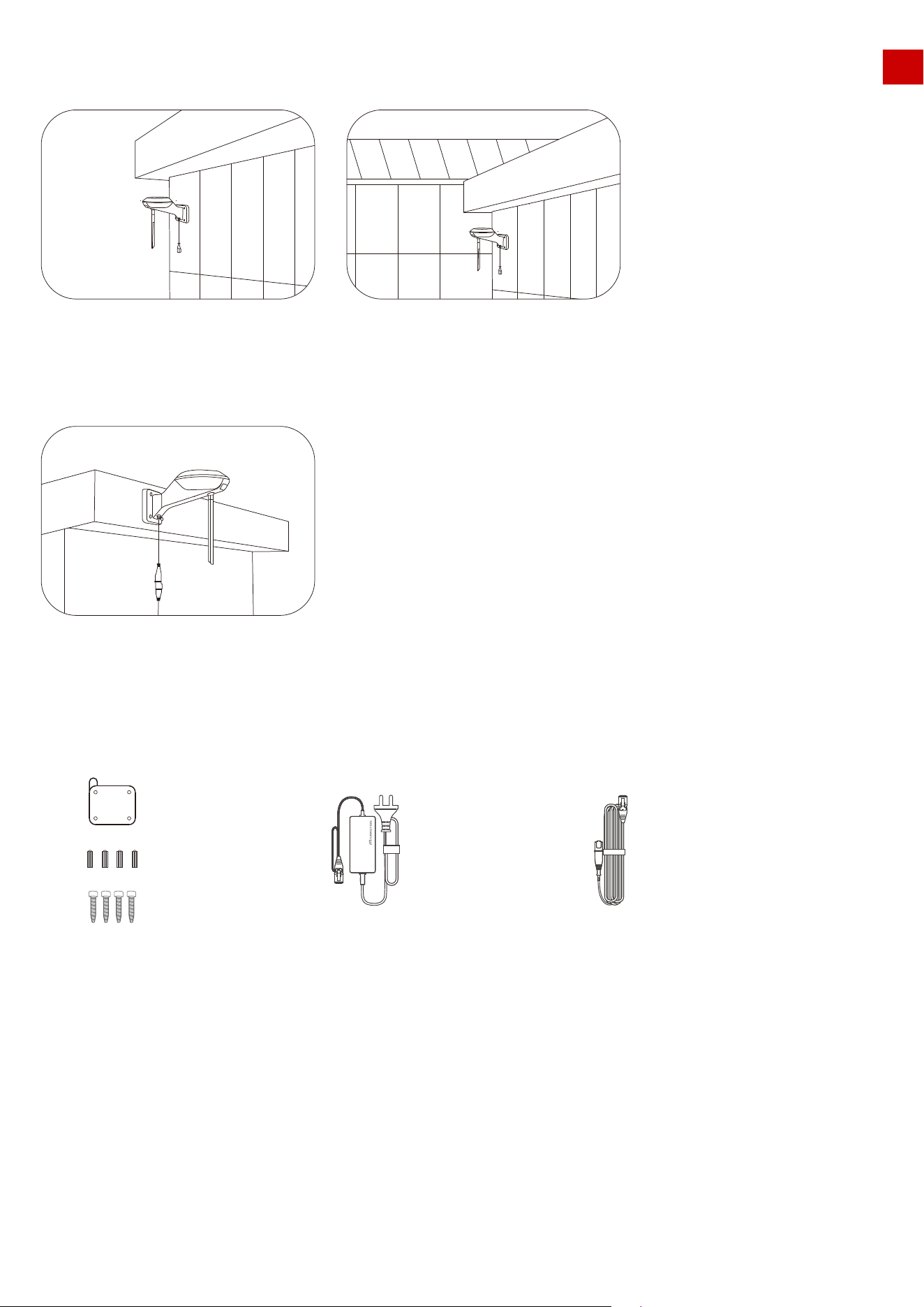
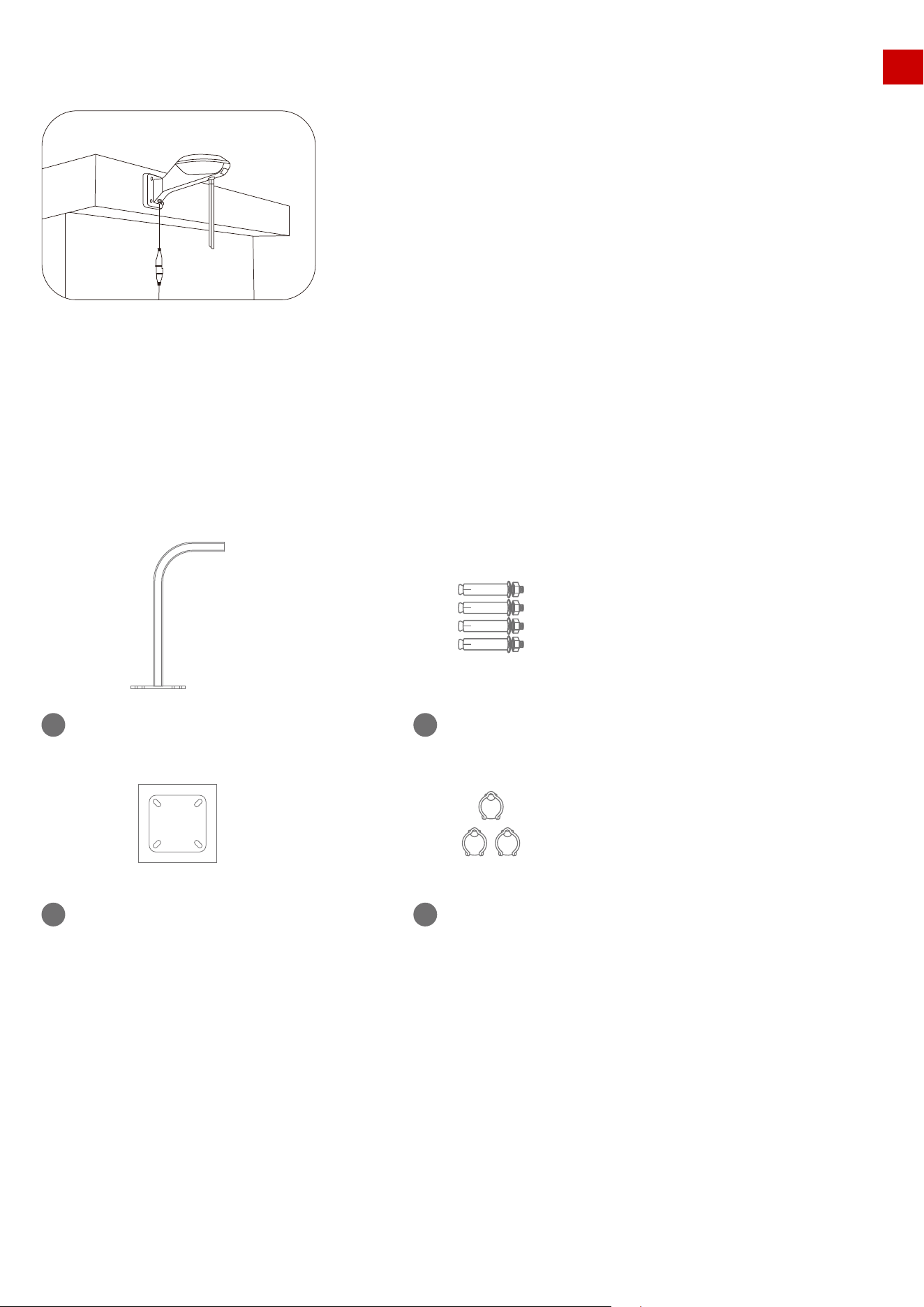
Installation Kit:
L-shaped mounting rod
1
Drilling position in dication sticker
3
Cable buckle*3
4
Expansion screw*4
2
EN
3.5 RTK reference station is installed separately from the charging station
& on the roof/wall
32
EN
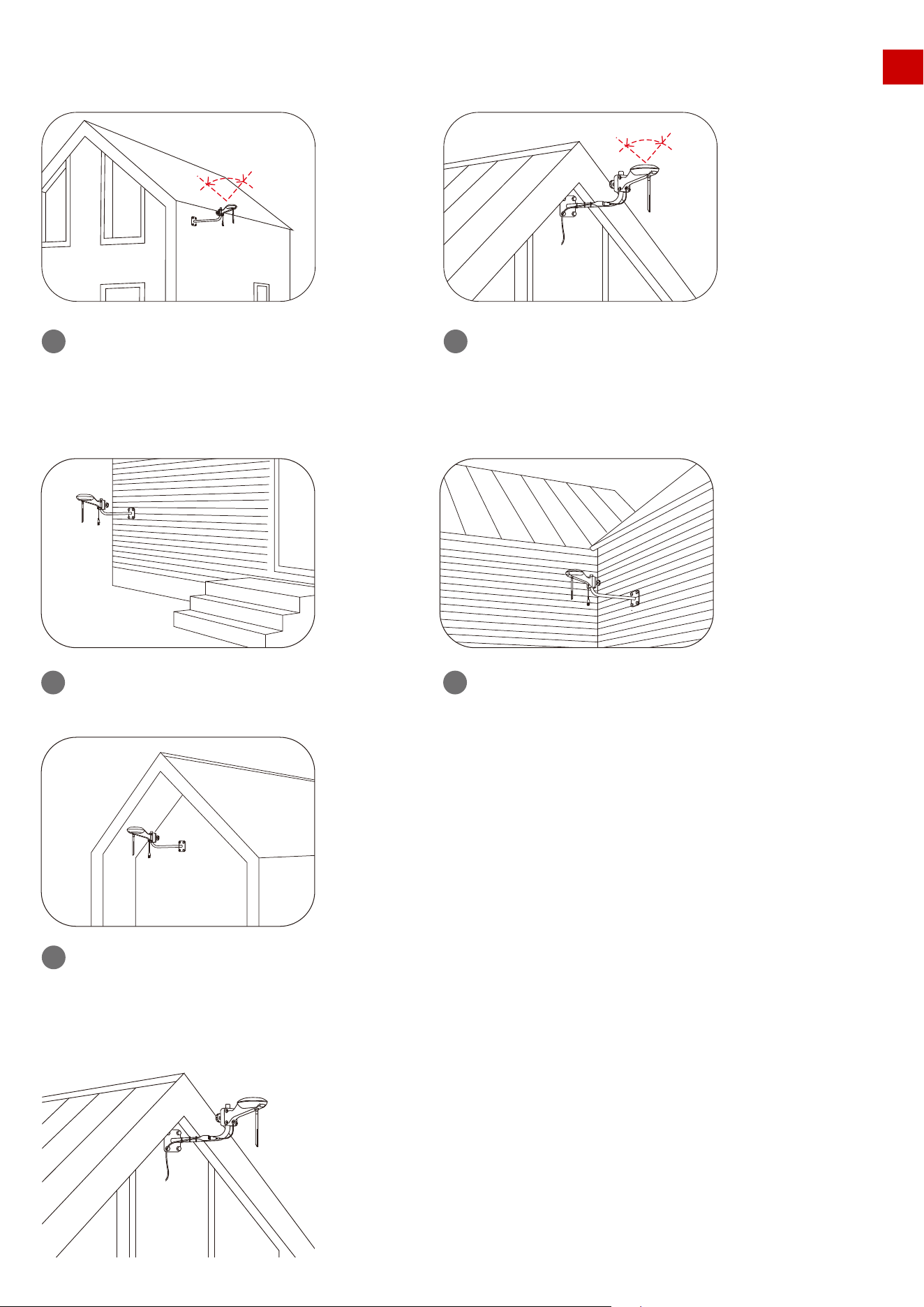
Overview of the installation when it’s completed:
Do NOT install under eaves or gutters.
3
Wrong settings:
Do NOT install on high wall.
1
Do NOT install antenna surrounded by
walls or in covered areas.
2
Correct settings:
≥ 90︒
≥ 90︒
Install on wall,in open area.
1
Install on roof far from any obstruction
that may affect signal.
2
33
EN
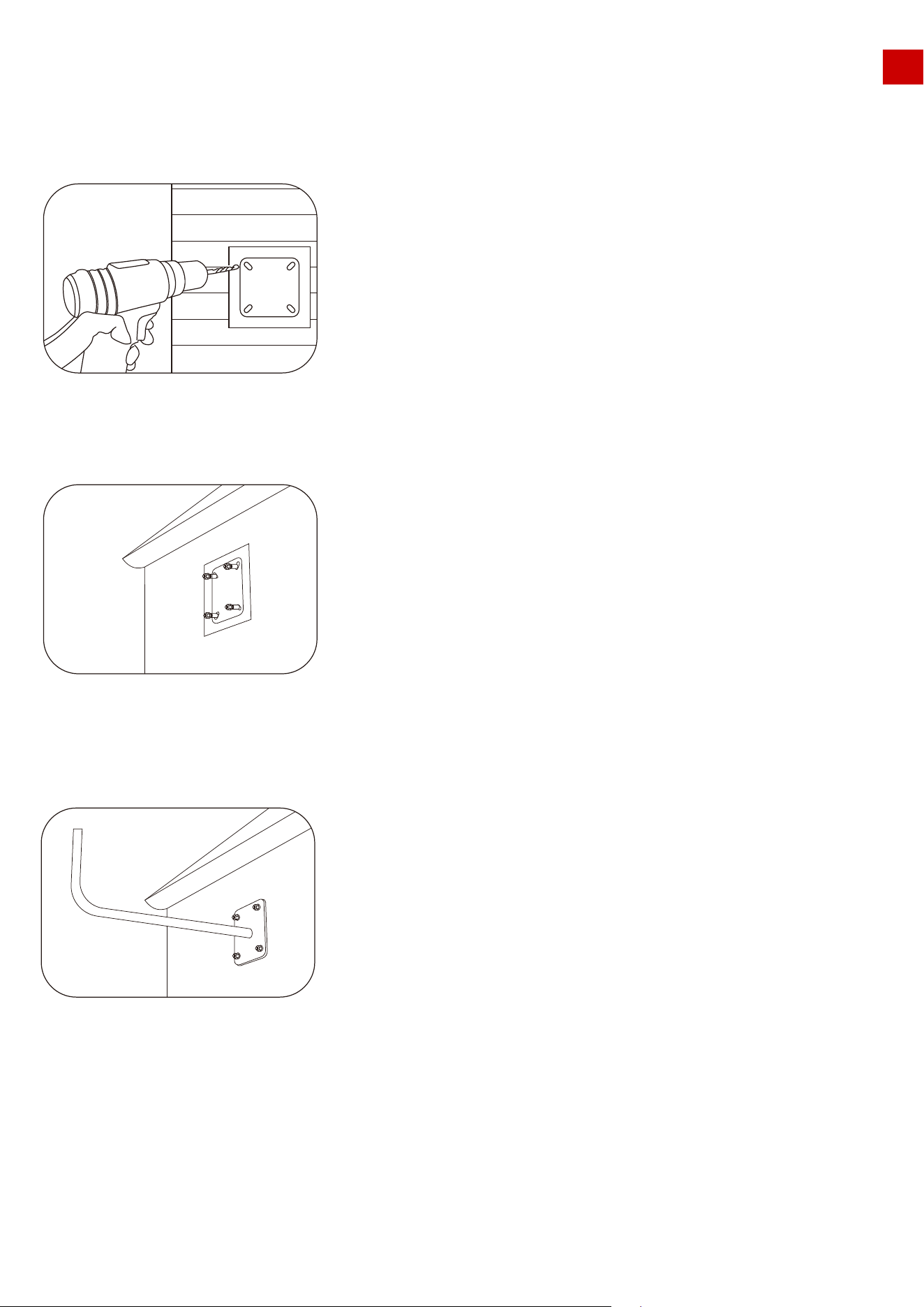
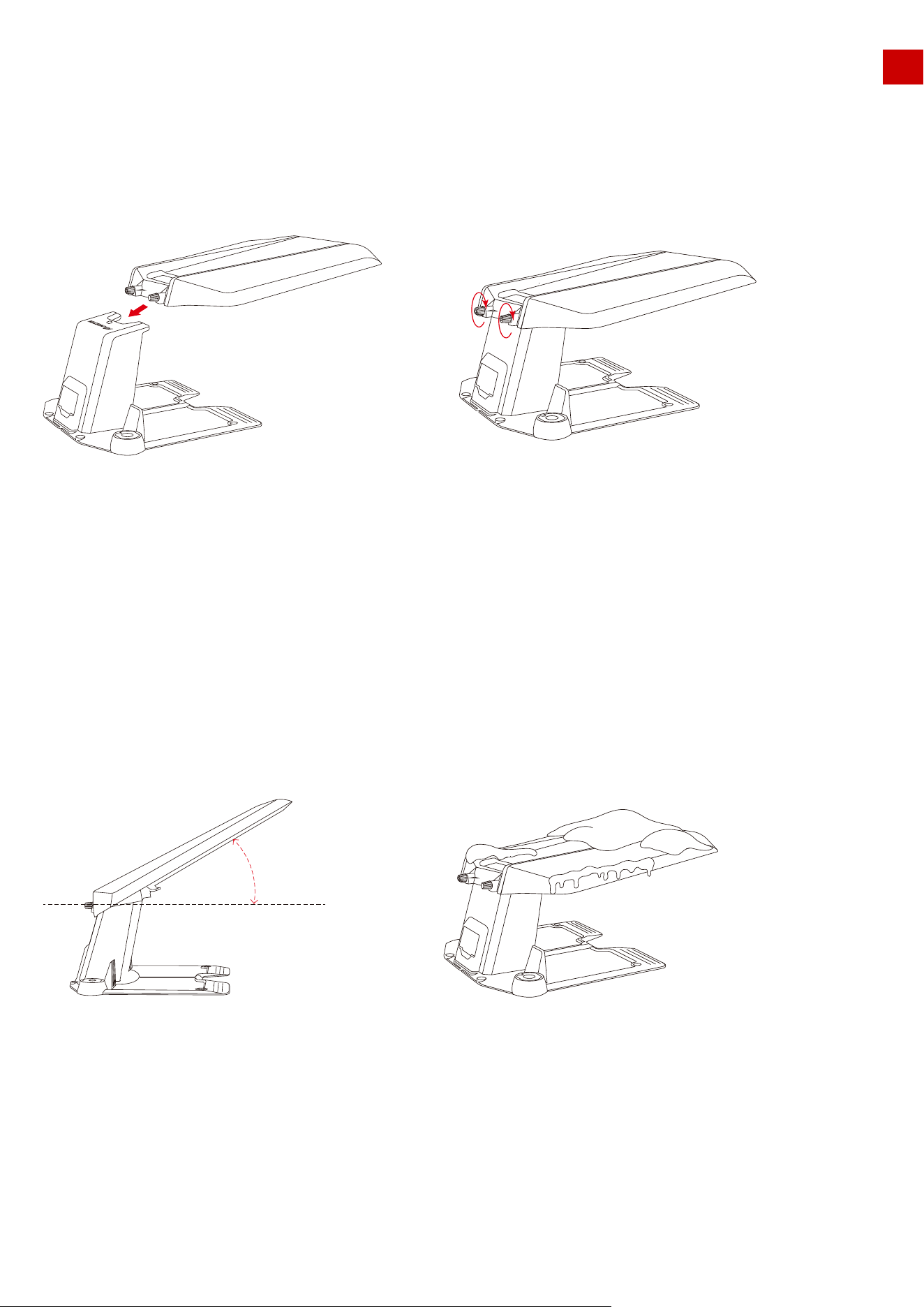
Installation Process:
1.Choose a suitable installation area on the outer wall of your house.
2.Stick the sticker on the wall indicating the position of the drilling hole and drill holes in the appropriate
positions.
3.Install the expansion screw in the drilled hole.
4. Fix the installation rod on the wall with expansion screws and tighten the nuts of the expansion screws with
a wrench.
34
EN
6. Connect the 10m end of the RTK extension cord to the RTK reference station and fix the cord harness
along the L-shaped installation rod with a cord tie.
5. Install the RTK reference station on the front end of the L-shaped installation pole (note that the
antenna must be installed on the RTK reference station first).
7. Connect the other end of the RTK extension cord 10 m (approx. 33 feet) to the RTK power adapter and turn
on the power.
8.The installation is complete.
35
EN
1.Do not place items on the top of the garage to avoid damage to the garage and affect the vehicle signal.
2.The garage cover can be lifted at an angle of 30°, but it cannot be opened into a vertical state. Do not
forcefully lift it upwards.
3.If there is heavy snow during winter in your area, it is recommended to store the mower indoors at this
time. If you need to use it, please clear the snow from the top of the garage before starting the mowing
task. Also, before opening the garage cover, check whether there is ice on the shaft. If there is ice, please
remove it before opening the garage cover.
3.6 LUBA garage installation
Fasten the garage cover on the top of the charging station from front to back and tighten the two screws on
the back of the garage cover to complete the installation of the garage.
Note:
max 30︒
36
EN
4. Preparation & Activation
4.1 MAMMOTION APP download & Installations
MAMMOTION LUBA is a 4-wheels-differential (4WD) robotic lawn mower. The 4WDenables LUBA to
break the limits of mowing jobs.
LUBA Series robot lawnmowers feature RTK GNSS navigation and virtual-mapping systems. These allow
users to customize their mowing tasks with different mowing areas and schedules on Mammotion APP.
They provide a picture-perfect lawn maintenance solution with a real hands-free experience.
Mammotion App Android Version:
Android App Download link:
Mammotion App iOS Version:
IOS App Download link:
37
Android App Download IOS App Download
EN
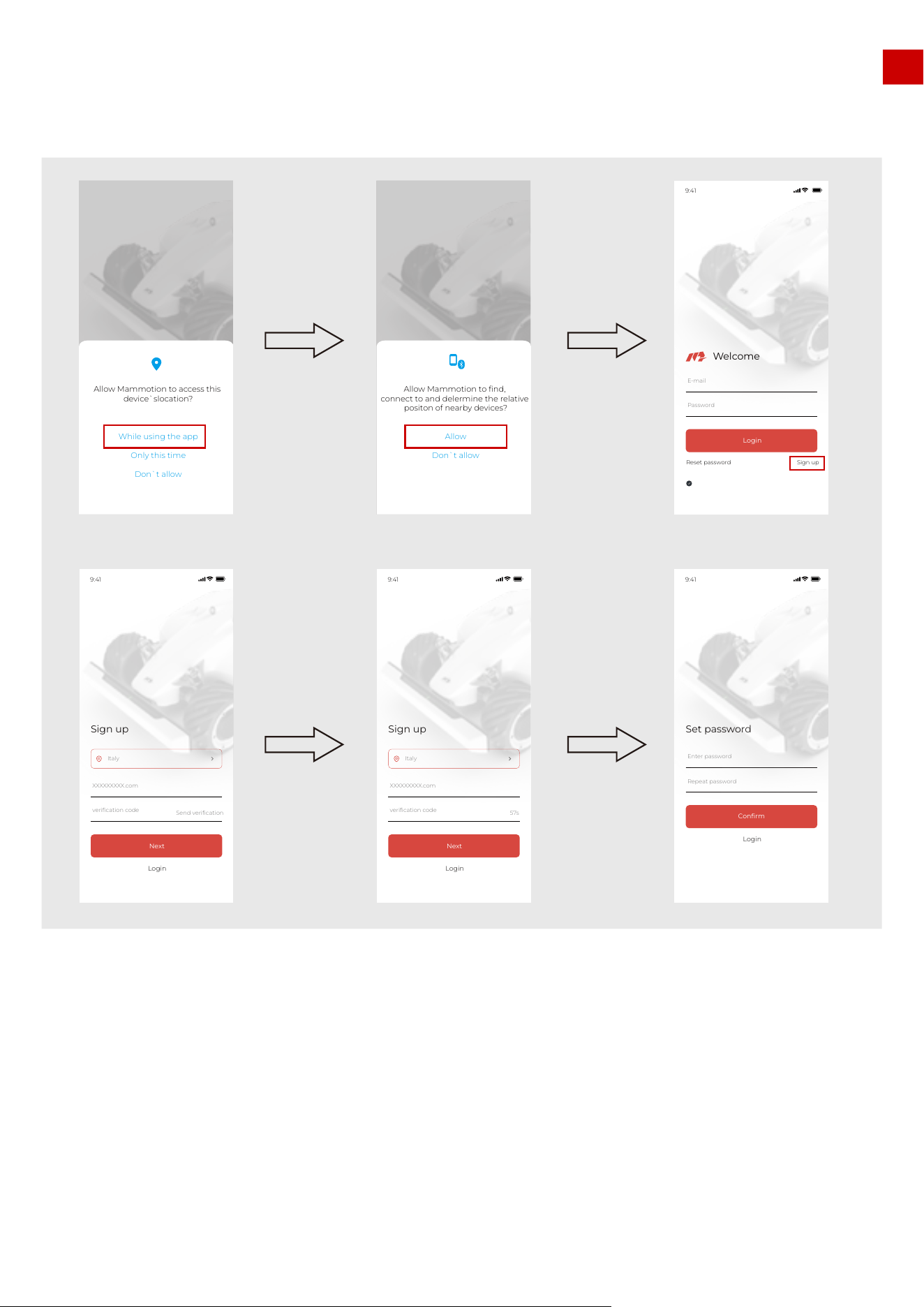
1.Switch on the Position and Bluetooth on your phone. Click Sign up and select the country and input
your email address.
2.Then click “Send verification”. A verification code will be sent to your email (if you don’t receive the verify
code, please check your spam folder or check the blacklist of your Email and wait several minutes and
retry to click the Code).
3.Input the verifying code (the verify Code is valid for 10min. If this time is exceeded please re-click the
“Send verification” button to get a new Code) into the App and click Next to set the password.
4.Click “confirm” to finish the sign up.
4.2 MAMMOTION account sign up and login
How to sign up:
38
Sign up
57s
9:41
Login
Italy
Next
verification code
XXXXXXXXX.com
Set password
9:41
Login
Confirm
Repeat password
Enter password
Sign up
Send verification
9:41
Login
Italy
Next
verification code
XXXXXXXXX.com
Sign up
Reset password
Welcome
Login
Password
E-mail
9:41
Login to consent Privacy Agreement User Agreement
Sign up
Reset password
Welcome
Login
Password
E-mail
Login to consent Privacy Agreement User Agreement
Allow Mammotion to access this
device`slocation?
While using the app
Only this time
Don`t allow
9:41
Sign up
Reset password
Welcome
Login
Password
E-mail
Login to consent Privacy Agreement User Agreement
Allow Mammotion to find,
connect to and delermine the relative
positon of nearby devices?
Allow
Don`t allow
Check your Email
to get verification
code
Set password and
click “confirm” to
finish the sign up
EN
1.Input your account and password to login.
How to login:
1. Please read the guide on Mammotion App carefully
2. Please make sure the secure key is correctly inserted into LUBA
3. Please make sure that your LUBA is powered on (with the LED indicator on the front bumper constant
green)
4. Make sure the distance between your phone and LUBA is less than 3 m (approx. 10 feet).
5. Make sure that there is good WIFI or hot spot signal
After users login to the App for the first time, it is necessary to Add your device to it.
Note:
4.3 Add your LUBA to the Mammotion App to continue setup and
self-checking:
39
Sign up
Reset password
Welcome
Login
Password
E-mail
9:41
Login to consent Privacy Agreement User Agreement
EN
If it shows “ ”, please wait a moment for things to complete
One LUBA can be connected to ONLY ONE Mammotion account. One Mammotion account can add
multiple LUBAs. Different phones can use the same Mammotion account. ONLY ONE phone can control
ONE LUBA at same time.
The task data and map data are stored in LUBA itself, so when you use different phones with the same
LUBA, the map and task data will be synchronized.
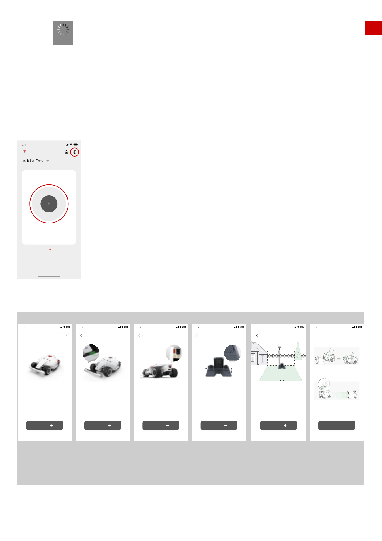
1. Click “+” to start initialization of LUBA
2. Read the guidelines of initialization carefully and make sure these guidelines are followed.
3. Long press(5s) the power button of LUBA and power on LUBA.
Process:
Loading
40
9:41
Add device
Place the phone as close to the target
device as possible.
+
Add a Device
1
Welcome to use the LUBA mower!
please dismantle and deploy it with me
Guidelines
9 41
Start
Skip
9 41
Install the base station and charger according
to the instructions to ensure thatThe upper part
of the base station is not sheltered
by buildings or trees,Turn on the power and wait
until the indicator turns green
Base station requirements
≥2M ≥2M
≥2M
Next
9 41
Install the base station correctly according
to the instructions
Base station installation
Next
Please take out the key from the box and insert
it into the key hole
Insert the key
9 41
Next
9 41
Insert the impact bar in front of the mower with
the indicator lamp facing up
Install the impact bar
Next
1.5M
Method I
Manually move the LUBA to the charging pile and ensure
it is in the charging state.
Place the LUBA 1.5 meters in front of the charging pile,
ensure that the rear of the LUBA is aligned with the
charging pile, andclick Start - Return - Start on he
vehicle body in turn.
Method II
OK
9 41
Connect charging
please read the
guidlines carefully
and follow the
guidlines
please incert the
front bumper to
LUBA with the
indicator facing up
please incert
secure key to LUBA
so that your can
switch on LUBA
Set chaarging
station at proper
place.
Set RTK reference
station at proper
place.
Set LUBA on
thechaarging
station
EN
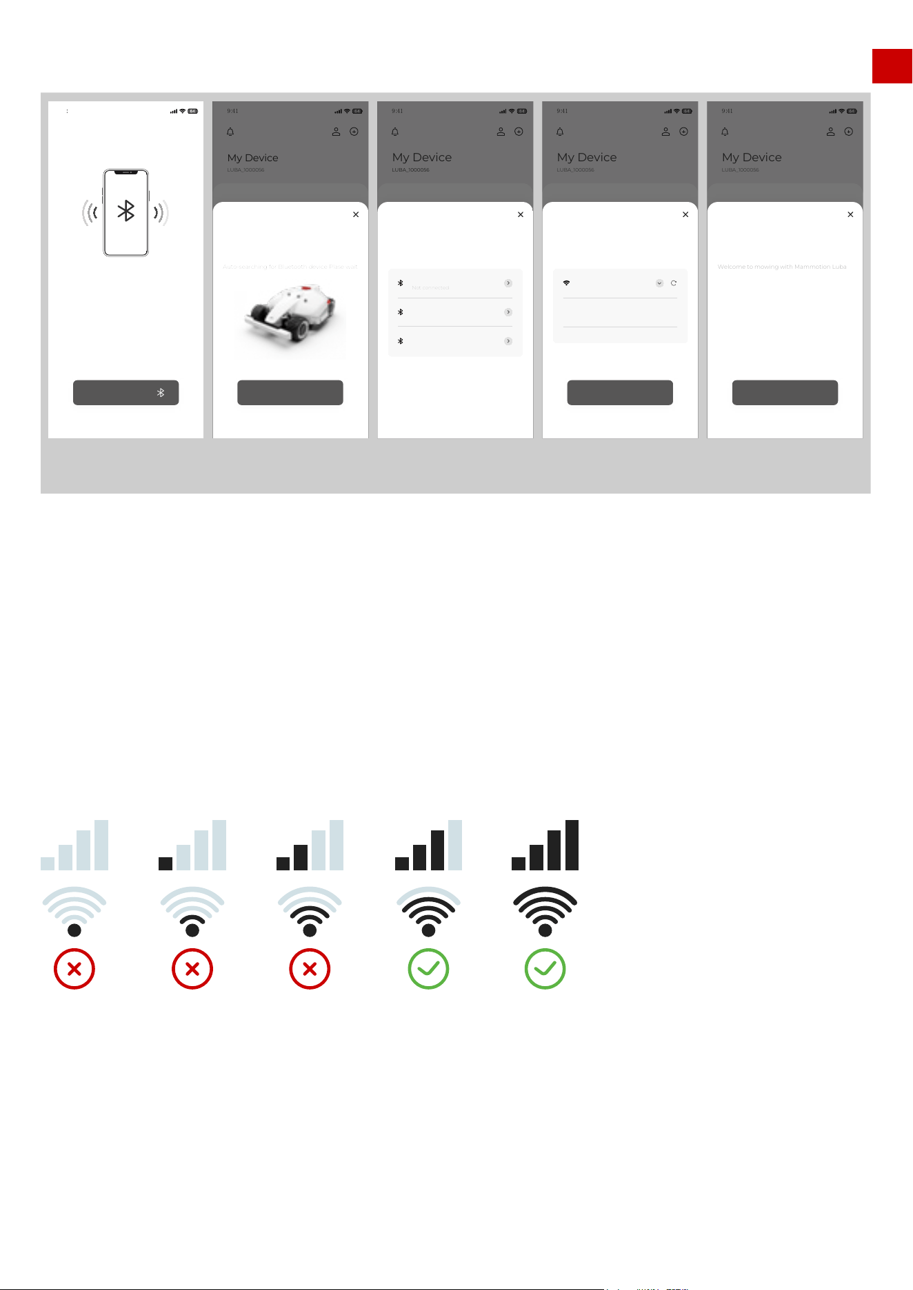
4. Add LUBA to your Mammotion account.
Activate LUBA: After the Bluetooth connection, it needs to connect LUBA to Wi-Fi & Hot spot for activa-
tion.
Select the Wi-Fi & hot spot, enter the password for this and then click Next. Wait until the App shows
Device is successfully added. Then click Finished.
Once you add LUBA to your account, it will not unbind automatically. Next time you switch on LUBA
using the same account, LUBA will still be there. And once LUBA is added, Internet (WIFI & hot spot) is
not necessary for map planning, mission setting and working.
However, if you would like to remotely receive information and check the status of LUBA, we recom-
mend that you cover your whole lawn area with WIFI
The connection is between LUBA and the MAMMOTION Cloud, it has nothing to do with how your
phone connects to the Internet, which means you do not have to connect your phone to the same WIFI
& hot spot as LUBA. You can also set your phone as a hot spot if your phone has good signal.
The App will search the nearby available Wi-Fi signals. Please note that we highly recommend you select
the WIFI & Hot Spot with the best signal quality. Otherwise, the activation may fail.
Note:
41
9 41
Please keep Bluetooth on the phone where
the APP is located and LUBA is on.
Select LUBA in the APP
Bluetooth pairing
Connecting Bluetooth
9 41
Enter LUBA
An Intelligent, Perimeter Wire Free
Robot Lawn Mower
Welcome to LUBA
LUBA_1000056
My Device
Add device(Luba-MTAJTT6F)
Connect added successful
Welcome to mowing with Mammotion Luba
Finished
9 41
Enter LUBA
An Intelligent, Perimeter Wire Free
Robot Lawn Mower
Welcome to LUBA
LUBA_1000056
My Device
Add device(Luba-MTAJTT6F)
2.Connect to Wi-Fi
OPPO 5G
12345678
Next
9 41
Enter LUBA
An Intelligent, Perimeter Wire Free
Robot Lawn Mower
Welcome to LUBA
LUBA_1000056
My Device
Add device
1.Bluetooth connectivity
Luba-878800
Luba-52800
Luba-634200
Not connected
Not connected
Not connected
9 41
Enter LUBA
An Intelligent, Perimeter Wire Free
Robot Lawn Mower
Welcome to LUBA
LUBA_1000056
My Device
Add device
1.Bluetooth connectivity
Mammotion Luba
Next
Auto-searching for Bluetooth device Plase wait
Switch on bluebooth
of your phone
Connect LUBA to
phone by bluebooth
Register your LUBA
to Mammotion via
WIFI/hot spot
Add LUBA
successful
EN
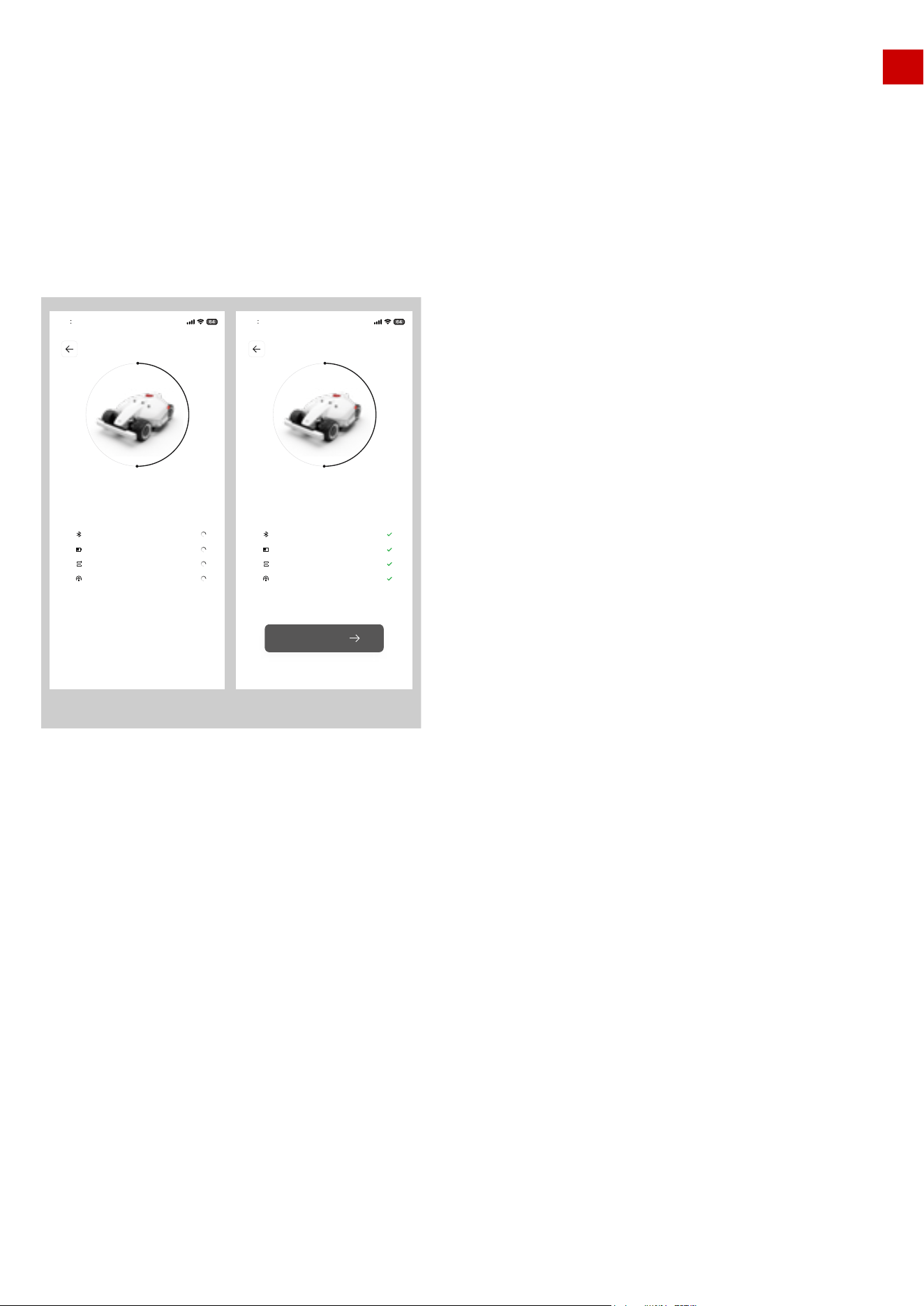
5. Self-checking:
After initialization for the 1st time before you use LUBA, please ensure that:
The RTK reference station is in the proper place.
The charging station at the proper place.
LUBA is on the charging station and the charging process is working and stable.
LUBA is switched on.
The positioning status is operational.
The self-checking indications should appear as below:
1.If “Bluetooth connection” failed, please check if Bluetooth of your phone is on, and the distance between
your phone and LUBA is not too great (should be within 5m);
2.If LUBA is on charging station but not charging (charging failed), please check if the charging station if set
in a proper place, and the charging port at back of LUBA is aligned with the charging port on the charging
station
3.If positioning status is bad (“RTK Reference station” failed), please check if the RTK reference station is in a
proper place, is switched on and is operational (indicated by a constant green light during daytime hours)
Note:
42
9 41
Self checking …
Bluetooth is connected
Charging state detection
State self check
Base station status
Enter LUBA
9 41
Self checking …
Bluetooth is connected
Charging state detection
State self check
Base station status
Self-checking Self-checking pass
EN
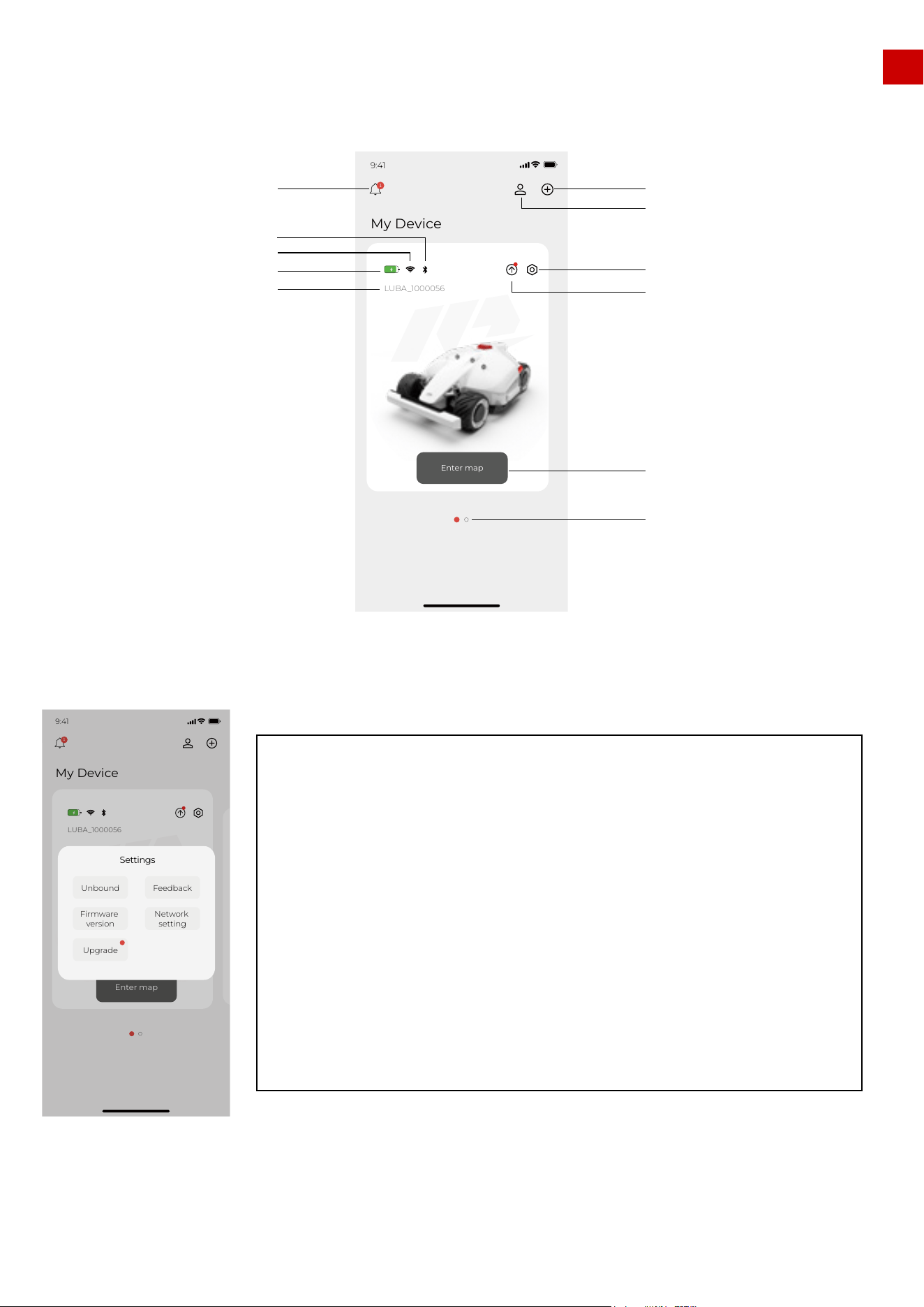
Unbound: Unbound the added LUBA.
Firmware version: Check the version of the Firmware of different parts on
LUBA.
Upgrade: Upgrade the Firmware, if there is a red dot, means you have new
firmware and can do the upgrade.
Feedback: When you meet issues when you use LUBA, you can here to
submit the feedback through our logs on the App.
Network setting: can choose to connect WIFI & Hotspot or disconnect.
The WIFI & Hotspot connection of LUBA does not affect the normal task and working of LUBA once
LUBA is registered and initialized for the first time.
Note:
4.4 Basic operation & App interface introduction on main page
The main page of the App is as shown below:
Settings:
43
My Device
9:41
1
LUBA_1000056
Enter map
Add new LUBA
Note
LUBA’s Bluetooth
LUBA’s WIFI
LUBA’s Battery
LUBA’s Nr.
User center
Settings
Upgrade
Enter map page
Different devices(LUBA) on
this Mammotion account
My Device
9:41
LUBA_1000056
1
Enter map
Feedback
Network
setting
Unbound
Firmware
version
Upgrade
Settings
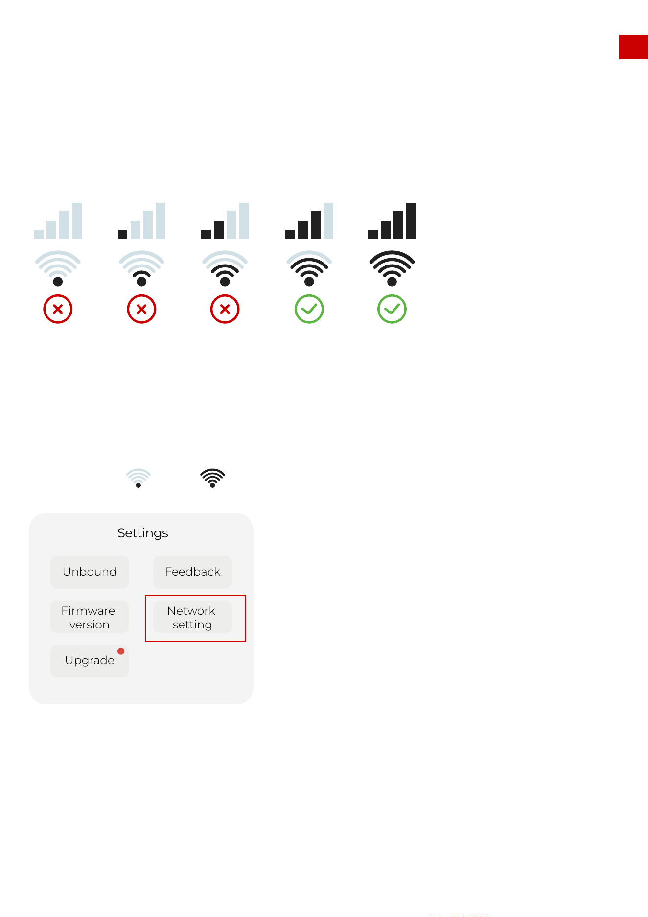
5.1 Preparation:
EN
1.Please make sure that your LUBA is powered on(with the LED on the front bumper green;).(图)
2.Make sure the distance between your phone and LUBA is less than 3 m (approx. 10 feet).
3.Make sure that there is good and stable WIFI or hot spot signal;
4.DO NOT switch off LUBA or disconnect the WIFI & Hotspot connection when upgrading, otherwise the
upgrading may fail.
1. Connect LUBA to the WIFI & hot spot by clicking “Network settings”. The WIFI & Hotspot connection is
complete when turns to .
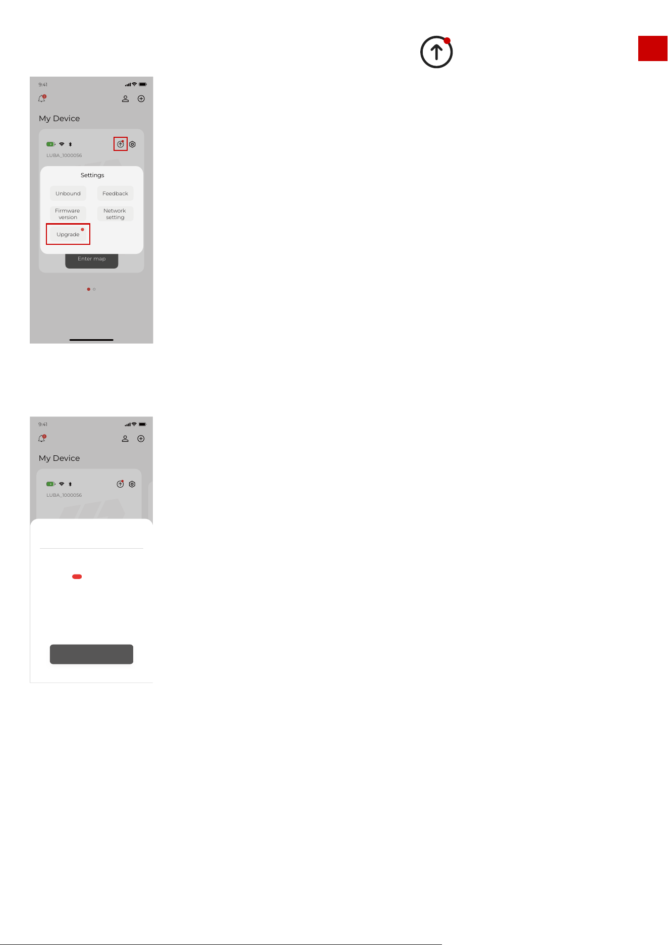
Upgrading Process:
5.Firmware upgrading:
44
Feedback
Network
setting
Unbound
Firmware
version
Upgrade
Settings
EN
5.Firmware upgrading:
2. To start upgrading: click the “Upgrade” button in the Settings or the symbol to start upgrading.
3. The message box will show you what is new in the firmware. Click “One click upgrade”
4. Wait until the upgrading is done (make sure the WIFI & Hotspot is available during the upgrade):
45
My Device
9:41
LUBA_1000056
1
Enter map
Feedback
Network
setting
Unbound
Firmware
version
Upgrade
Settings
My Device
9:41
LUBA_1000056
1
进入地图
Firmware upgrade
1.3.2.243
·add new feature of led control
·fixed some issues
Luba-MATFBJZP
One-click upgrade
NEW
EN
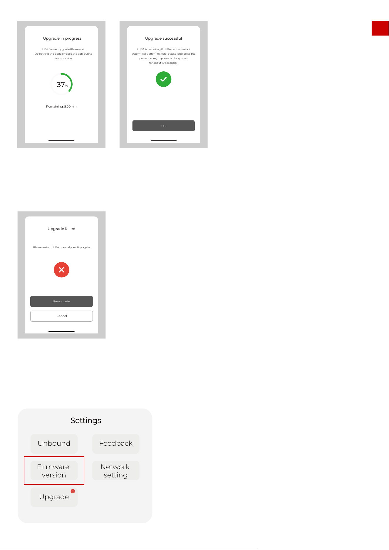
5.When the APP shows that LUBA is successful upgraded, the LUBA will automatically switch off, Please
LONG Press (Press about 10s until the LED side lights is on) the power button of LUBA to switch on.
6. If the upgrade failed, please check the WIFI & Hotspot connection and try again.
7.Check if the firmware of LUBA and APP have already reached the newest firmware by clicking “setting
version”. If yes, then you can start LUBA with the newest firmware now. If no, please contact us to solve
the issue.
46
37
%
Remaining: 5.00min
Upgrade in progress
LUBA Mower upgrade.Please wait...
Do not exit the page or close the app during
transmission
Upgrade successful
LUBA is restarting.If LUBA cannot restart
automtically after 1 minute, plaese long press the
power-on key to power on(long press
for about 10 seconds)
OK
Upgrade failed
Please restart LUBA manually and try again
Cancel
Re-upgrade
Feedback
Network
setting
Unbound
Firmware
version
Upgrade
Settings
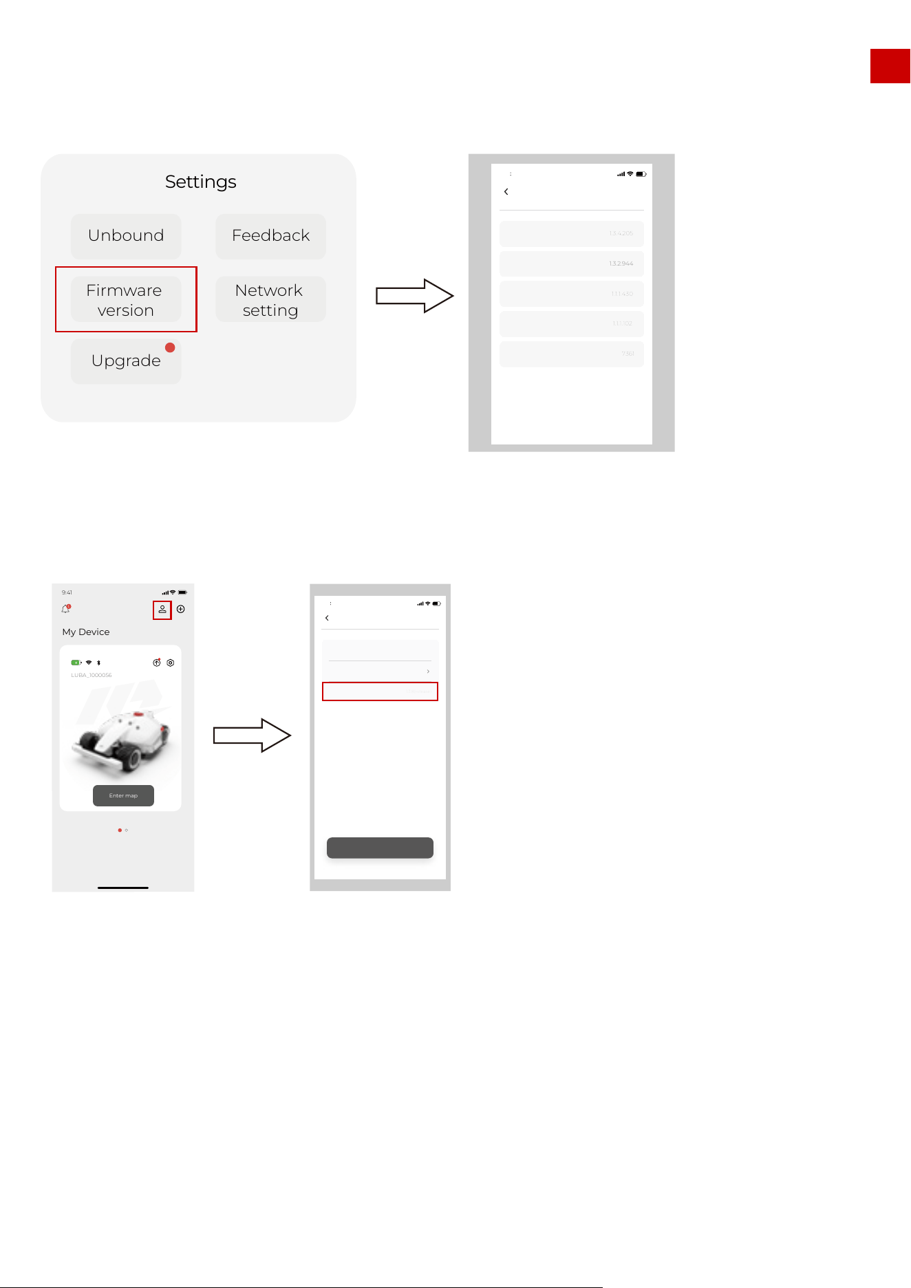
5.2 How to check firmware version and App version:
Check firmware version:
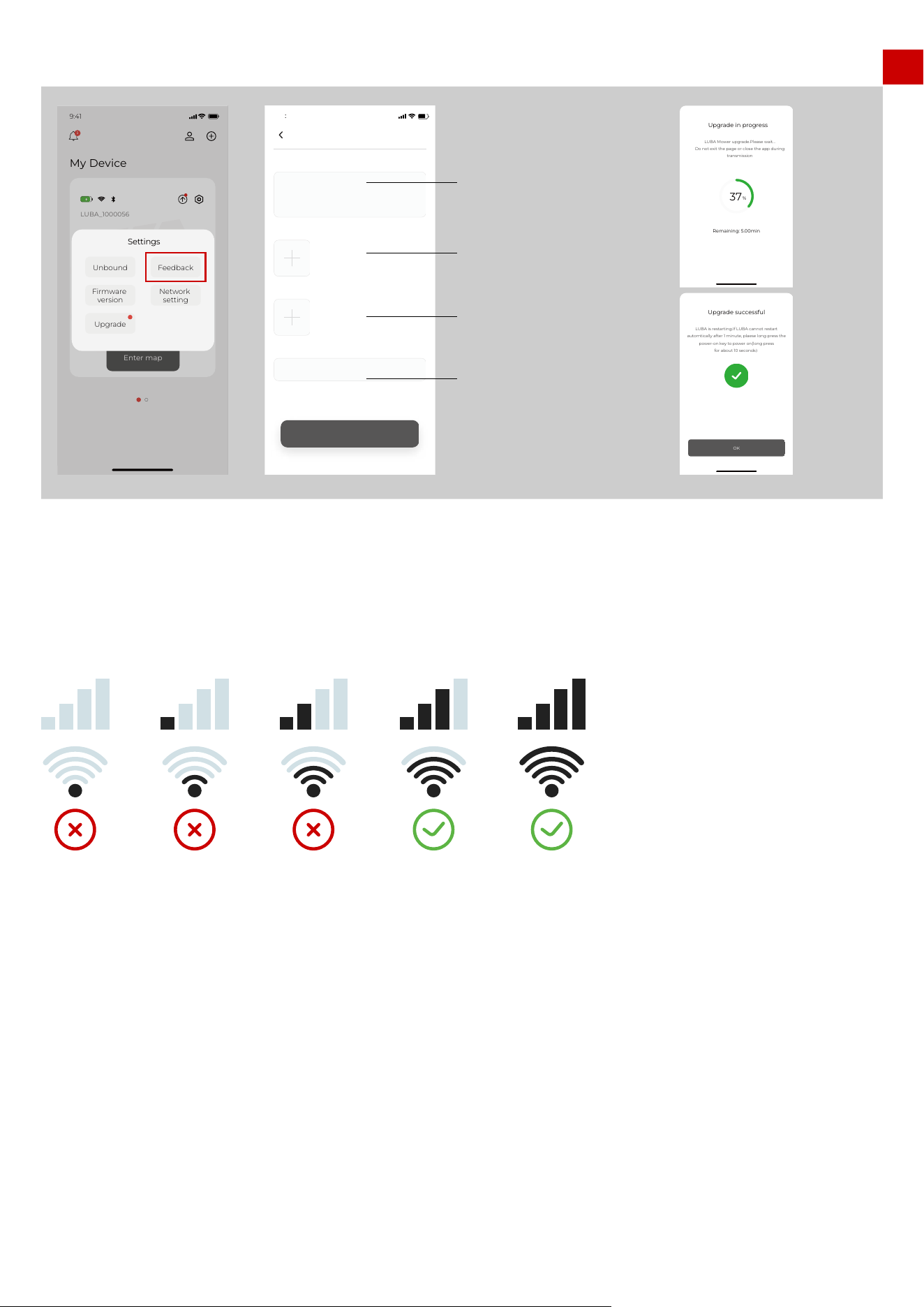
5.3 Reporting Issues & Logging feedback
Important information about how to record feedback:
1. Please describe HOW the issue is affecting things, WHEN and WHERE the issue appears. This will help
us a lot to fix the issue.
2. Please take images or video if possible and also upload the images and videos to us.
Check App version:
EN
47
Feedback
Network
setting
Unbound
Firmware
version
Upgrade
Settings
Firmware version
DeviceVersion
Main controller
Communication module
Right motor driver
Rtk rover station
1.3.4.205
1.3.2.944
1.1.1.430
1.1.1.102
7361
9 41
My Device
9:41
1
LUBA_1000056
Enter map
User Center
9 41
Account name
Version number
Log out
1.3.8(release)
EN
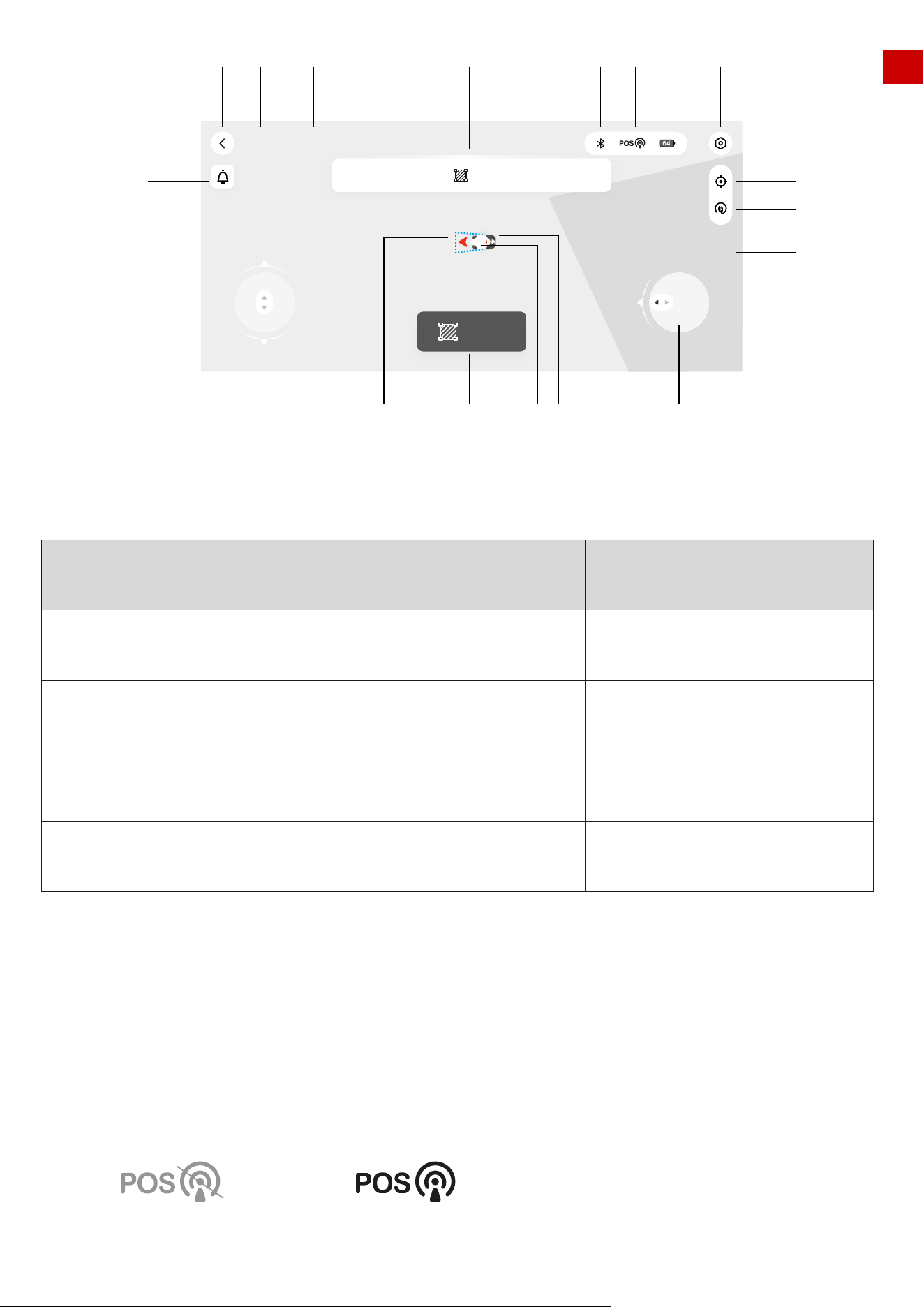
6. Basic operation & App interface introduction on
the Map page
Below is the interface of the map & control page:
Feedback process:
1.During the feedback process, please make sure that both the Bluetooth and WIFI & Hotspot connection is
good. And also ensure that the distance between your phone and LUBA is less than 3 m (approx. 10 feet)
Note:
48
My Device
9:41
LUBA_1000056
1
Enter map
Feedback
Network
setting
Unbound
Firmware
version
Upgrade
Settings
Feedback
9 41
Question feedback
Contact E-mail
Picture
Video (required)
Submit
Please fill in question
E-mail
37
%
Remaining: 5.00min
Upgrade in progress
LUBA Mower upgrade.Please wait...
Do not exit the page or close the app during
transmission
Upgrade successful
LUBA is restarting.If LUBA cannot restart
automtically after 1 minute, plaese long press the
power-on key to power on(long press
for about 10 seconds)
OK
Describe the issue/odd
performance, and describe
what the issue is, when and
where the issue apprears.
Upload images of the issues,
your lawn, and screenshot of
Mammotion APP.
Upload Video of the issues
including how LUBA oddly
performs, your lawn, and the
Mammotion APP.
Your email address
EN
1. Back to previous page: to main page
2. LUBA status. The status are as follows:
3..Device number
4.Guide message box
5.Mower battery power
6.Bluetooth connection status. If Bluetooth is connected successfully, it will be shown as a black icon. If
not connected successfully, then the icon is gray.
7.Positioning status: The position status could be “Fine” or “Unavailable”. If “fine” LUBA can work normally,
if “unavailable” LUBA could not do the automatic navigation and will not be able to function.
If your LUBA stops working at some point, please first check the positioning status.
STATUS
charging
returning
working
connection path planning
initializing
ready
task planning
offline
paused
obstacle planning
lock
Positioning finePositioning unavailable
49
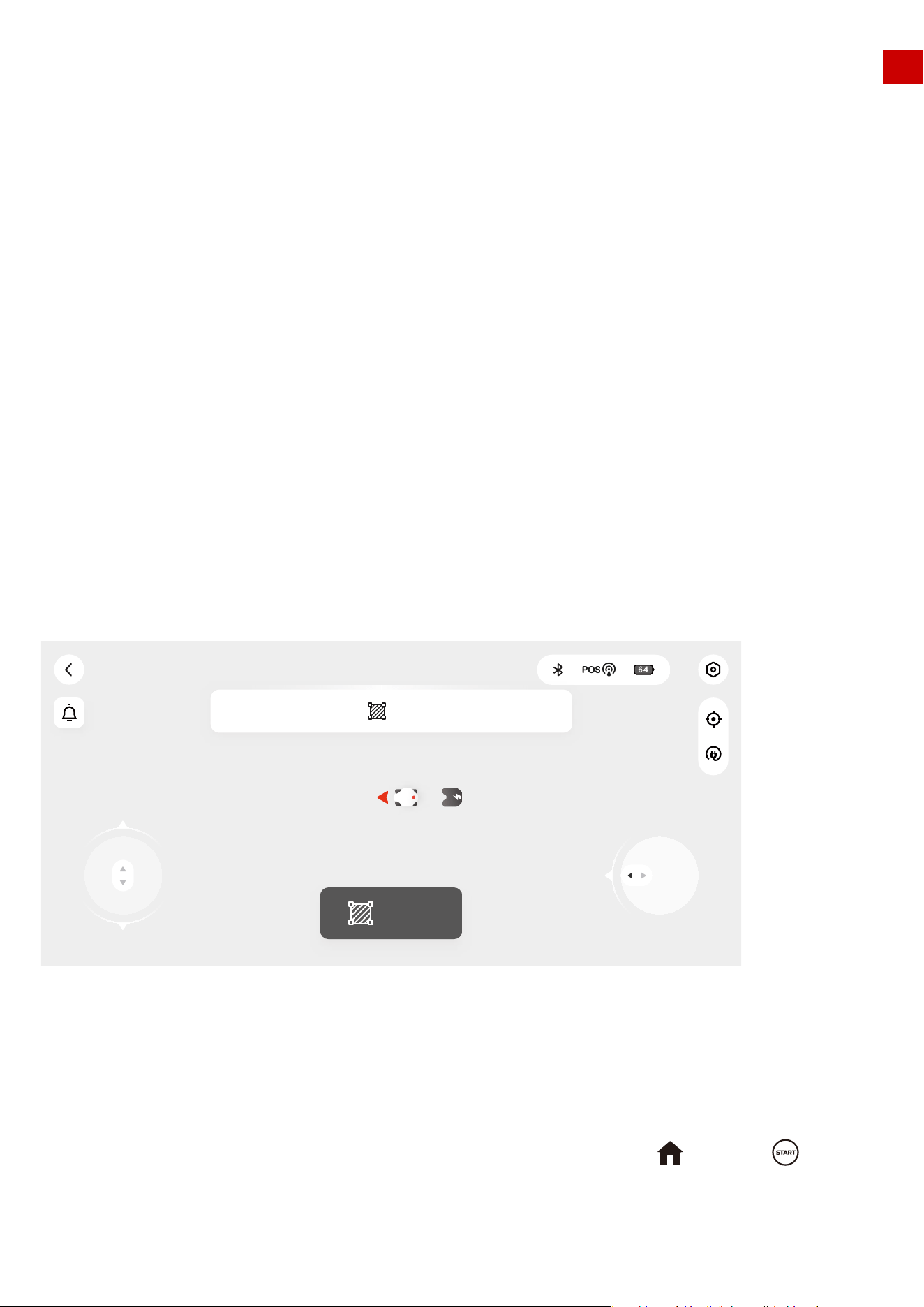
Ready! (Luba-MATJTT6F)
Create
Please click the button to start planning task area
1 2 3 4 6 7 5 8
9
10
11
121314151617
18
Ready!(Luba-100020)
EN
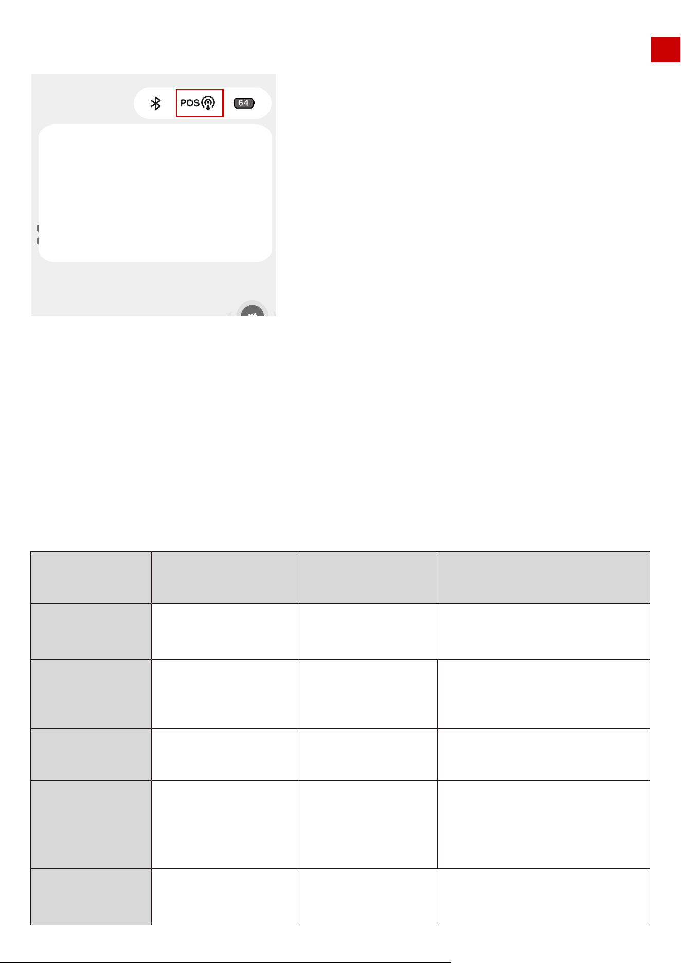
Clicking the “POS” symbol will show more detailed information about positioning status. As shown below:
Bluetooth quality: shows the strength of the Bluetooth connection.
Number of satellites: the Number of satellites observed by LUBA. If either of the 2 numbers is less than
20, there will be a risk that the positioning status may be “unavailable”. If you meet this issue, please
drive/set LUBA and the task area to a more open-sky area to let LUBA receive more satellite signals from
the sky.
Positioning status: “4” if RTK is working fine, other values indicate problems as described in the table
below:
Age of differential:Time delay of the RTK reference station data
S.D.:standard deviation of positioning.
Bluetooth quality
Number of
satellites
Positioning
status
meaning
reference value reason of out of reference value
Age of
differential
S.D.
The quality o bluetooth
connection
the Number of satellites
observed by LUBA
Positioning status
Time delay of RTK reference
station data
standard deviation
of positioning
Phone too far from LUBA
LUBA can not gel enough satellite
data(please check number of satellites).
see the sheet below
1.RTK reference sation is constant
Defect(0)
2.The distance from reference station and
LUBA is too far.3.there is high concrete
wall/ large metal/ very dense tree wall
between reference station and LUBA
positioning unavailable
Good
>20
4
0<Age of differential<20s
0<S.D.<0.1
50
Create
Bluetooth quality Good(-54)
27(21)
0.1 56,0.254
5
4.5
Number of satellites
Positioning status
Age of differential
S·D
EN
Preparation:
Positioning
status
0
1
2&4
5
meaning accuracy reason to do
no
positioning
no satellite signal received at all
( in the room/ LUBA covered/ defect)
single point
positioning
Several
meters
20cm-1m
less than
5cm
float
positioning
FIX
positioning
8.Setting:
1.) LUBA’s speed when under manual control (can only be set when manually controlling LUBA and not
when creating a task)
2.) If rain sensor on or off
3. )Obstacle avoidance logic setting
9.View returns to the center of the map
10.Call back and recharge
11.Background map
12.Manually drive using the steering clockwise/ anti-clockwise button
13.Charging station
14.LUBA symbol, red arrow points to direction
15.Create task. Click here to create a new map with mowing task.
16.Recharging area
17.Manually drive forward/backward button
1.Ensure you have already done the MAMMOTION account sign up, the LUBA activation and added
LUBA to your account.
2.Make sure that both the LUBA firmware and APP are of the newest version.
3.You have already installed the charging station and the RTK reference station in a the proper place.
4.Check your lawn, make sure that there are not water-filled holes which can cause damage to the
product.
5.Consider the layout of your house, your lawn and all obstacles, and then decide where to set the virtual
boundaries of the task area and no go zone(s).
LUBA does not received RTK
reference station at all,(please
check "age of differential ) :
1) RTK reference station defect.
2) LUBA too far from reference
station
3) the signal transmit path from
reference station and LUBA is nearly
fully obstructed/covered
1.LUBA can not get enough
satellite data (please check
“number of satellites”)
2. RTK reference station does not
get enough satellite data( check
the LED on reference station)
Fine positioning status
Drive LUBA/set task area to a more
open sky area.
1. check if the LED on RTK
reference station is constant
green.
2 check the distance from
reference station and LUBA
3. check if there if high concrete
wall/large/metal/very dense tree
wall between reference station
and LUBA
4.move reference station to a
more opensky area
1 Set RTK reference station to a
open area.
2 Drive LUBA/set task area to a
more opensky area.
Good, can use LUBA NOW!
51
EN
6.Fill in any large holes in the lawn.
7.When LUBA is working, make sure that there are no people, children, pets or other moving things on your
lawn.
8.We highly recommend you set any areas with obvious holes, gullies, tree roots or other obstacles as no go
zones.
9.LUBA can only be used when the front bumper is attached and the LED indicator on the front bumper is
on.
6.1 Map page when creating Task:
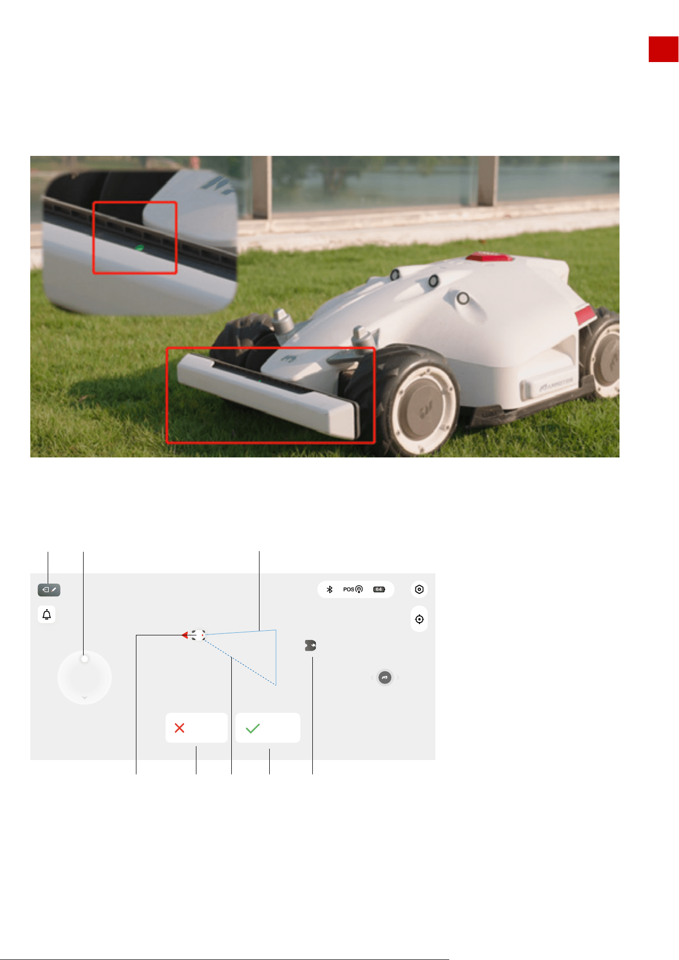
1. Back to previous page (map & control page)
13.Charging station symbol
14.LUBA symbol, red arrow points to the direction of travel
17.Manually drive forward/backward button
19.Boundry of task area (updates as the area is drawn)
20.Direction line from LUBA’s current location to the start point.
21. “Done” button, press this button to finish the work planning and close your working area
52
Work planning(Luba-100020)
Done
Cancel
1 17
13212214 20
19
EN
Note: if “Done” clicked, this means that a task area will be created immediately, one boundary will be
from the start point to LUBA’s current location, e.g. if in the image above, the “Done” is clicked, a triangu-
lar task area will be created.
Another way to finish task creation is to manually drive LUBA back to the task area start point. Once
LUBA reaches the start point or other point on the already existing boundary then task creation will be
complete.
We recommend you use this second way to finish creating the task area, or at least click the “done”
button when you are near the start point.
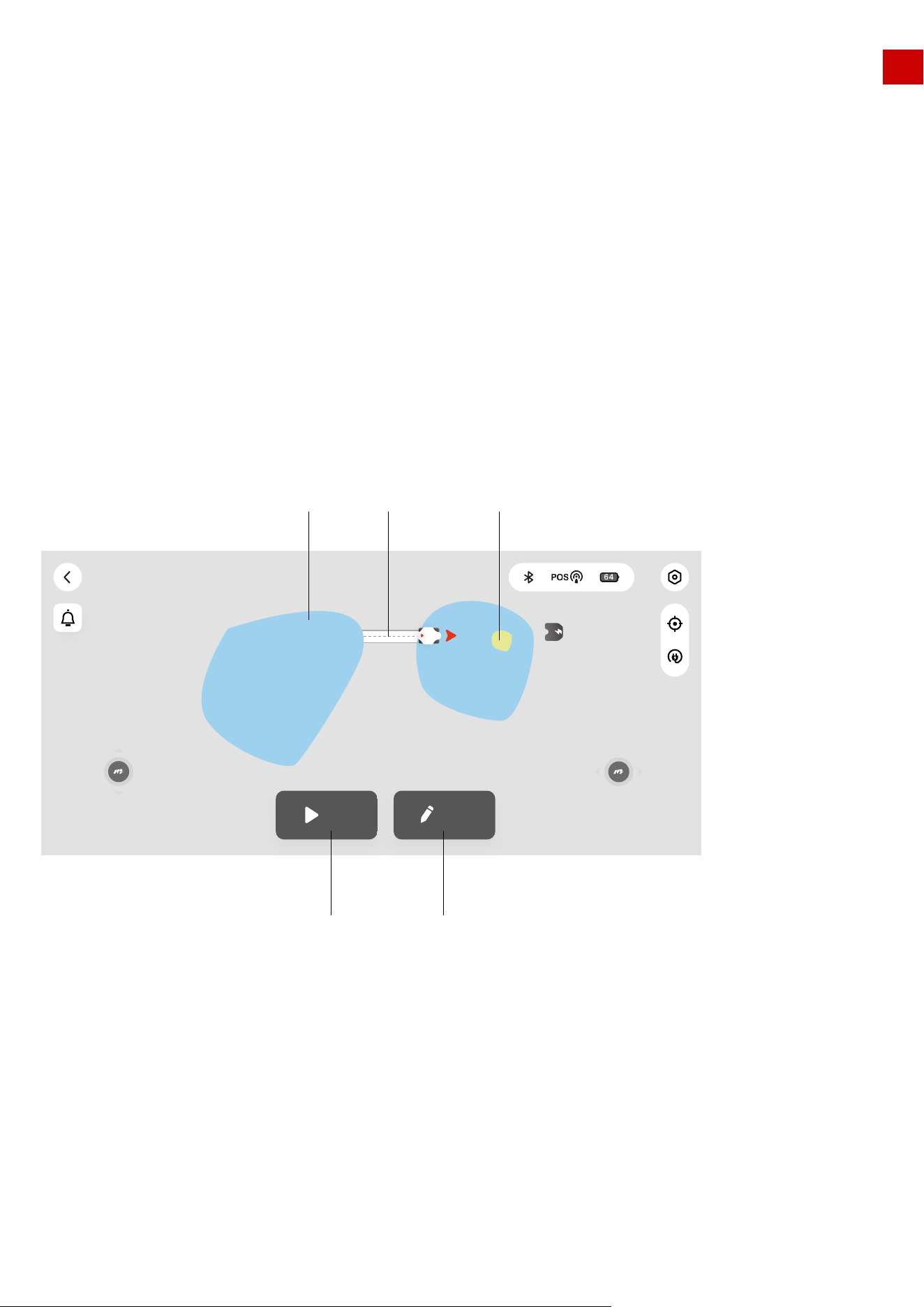
22.“Cancel” button, press to cancel task planning.
When creating a task, the “call back and auto recharge” button is unavailable. You need to cancel or
finish creating the task first.
23. Task area(selected)
24. Connection path
25. No go zone
26. Edit the task area (add/delete/change task area/path/no-go zone)
27. Start the task
Note:
6.2 Task area selected( can start mission or continue edit the task area)
During the task:
53
Ready!(Luba-100020)
Mow Edit
23
27 26
24 25
EN
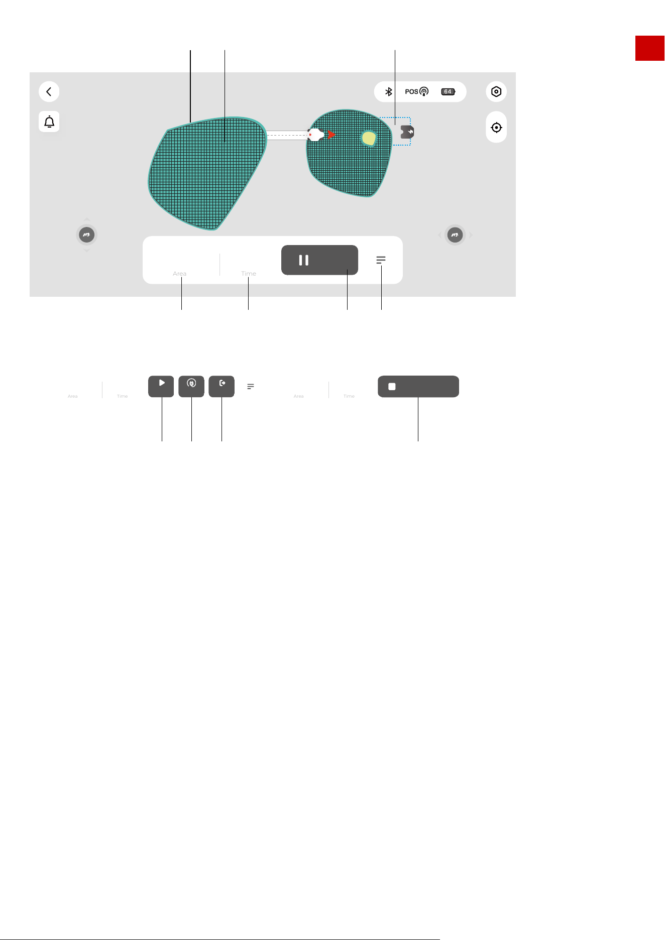
28. Working route (at boundary)
29. Working route
30. Recharging area
31. More commands
32. Pause (when LUBA is working automatically)
33. Estimated task time (charging time is not included)
34. Task area
35. End task (go back to charging station, the task will not continue, when LUBA is 95% charged)
36. Set break point and go back to charging station and charge.
37. Continue working (this “Continue” button only works when the “Pause” button on the App is clicked. If
the STOP button on LUBA is pressed, it is necessary to use the buttons on LUBA to unlock and continue.
38. Cancel the recharging progress
54
Working(Luba-100020)
200 24
min
Time
Area
Pause
m
2
34 33 32 31
302928
200 24
Time
Area
Continue Recharge End
m
2
min
Cancel Recharge
200 24
Time
Area
m
2
min
37 36 35 38
EN
7.Create a task
7.1 Initialization before creating a task:
1.After the “LUBA quick start installation” in Chapter 3 both the RTK reference station and the charging
station should be properly installed. (If NOT, please go back to Chapter 2 and 3 and finish the installation)
2.After the “LUBA first setup and self-checking” in Chapter 4.3, LUBA should be powered on, upgraded to
the latest version and positioned on the charging station with functional positioning status. (If NOT, please
go back to Chapter 2,3 to finish the proper installation of the charging station and the RTK reference
station, and Chapter 4 for the initial setup and checking. If LUBA is not already on the charging station,
please drive LUBA to 2m from the front of the charging station, with the rear facing the charging pins, and
use the App to call back LUBA):
3.The location of charging station and LUBA should be indicated on the map, as shown below, the posi-
tioning status should be good, and LUBA’s status should be “Located”
4.Click “Next” to start initialization.
1.Remove debris, piles of leaves, toys, wires, stones and other obstacles from the grass. Make sure no
children and pets are on� the lawn.
2.We highly recommend you leave 10-15cm distance if you drive LUBA along the edge of a wall / fence /
obstacles / ditches
Note:
55
Located
Congratulations! LUBA positioning success
Next
Located
Congratulations! LUBA positioning success
Next
Automatic pile lowering test
Click the automatic pile lowering button at
the bottom, and LUBA will lower the pile first
and then return the pile
1.5M
Next
Located
Automatic pile down
EN
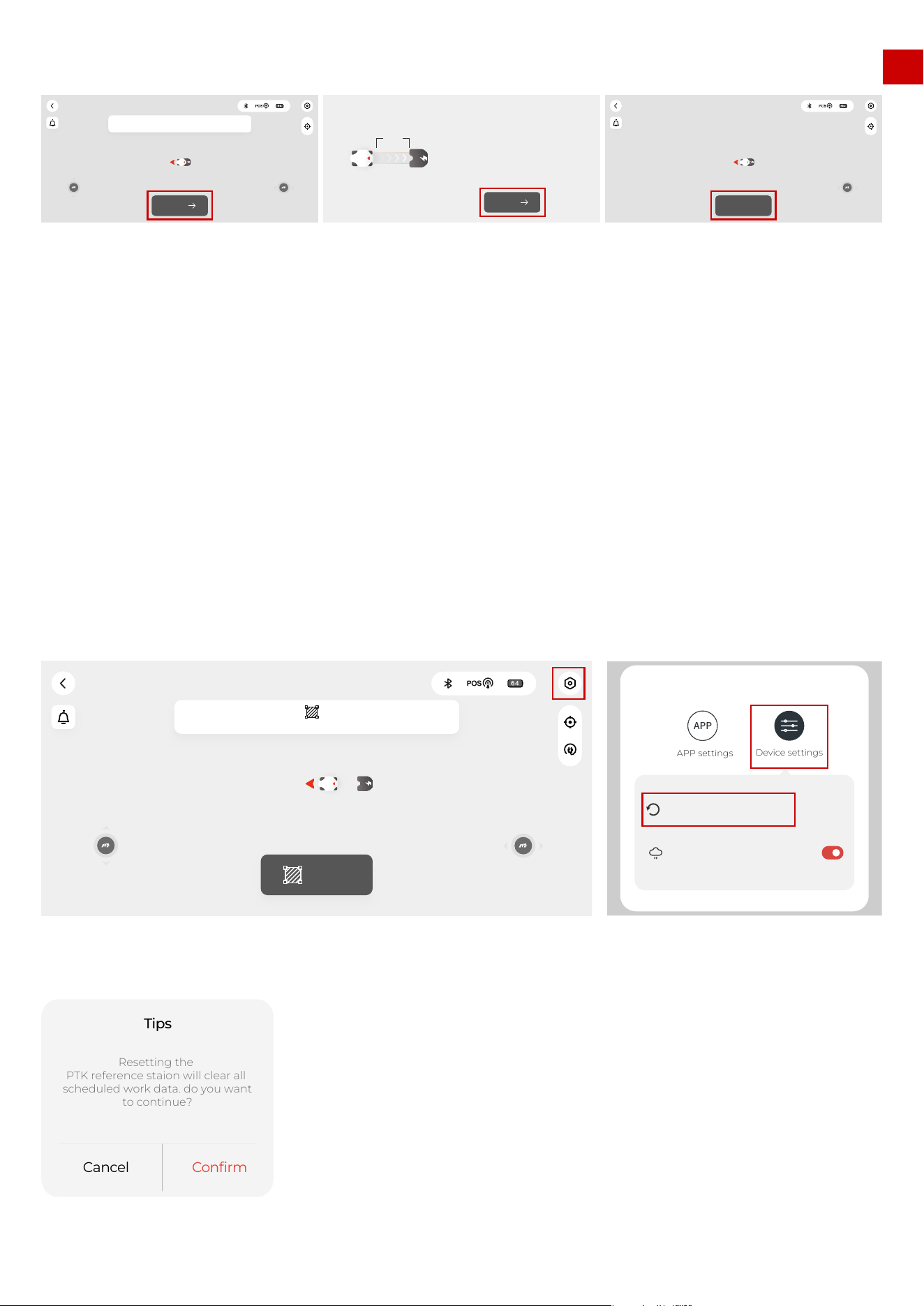
1.Set the RTK reference station/charging station in their proper place.
2.Put LUBA on the charging station and ensure that the positioning status is “Fine”
3.Select Setting -> ”Charging station reset”
4.Any existing task area(s) and schedules will be deleted because the whole system is changed.
5.As described in Chapter 6.1, go through the initialization until LUBA’s status turns to ” Ready!”
How to redo the initialization:
5.After the initialization, LUBA’s status turns to “Ready” and you can now start creating a task as shown below.
1. If both the charging station & the RTK reference station are not moved, next time you restart LUBA
(even if after a winter break) or add/ change / delete the task area, you do not need to re-do the initializa-
tion. As long as LUBA’s status is “Ready”, it can continue working.
2. However, if you move the charging station & RTK reference station, you should redo the initialization
because the coordinate system of LUBA and task area will need to be changed.
Note:
56
Located
Congratulations! LUBA positioning success
Next
Automatic pile lowering test
Click the automatic pile lowering button at
the bottom, and LUBA will lower the pile first
and then return the pile
1.5M
Next
Located
Automatic pile down
Create
Please click the button “ ”to start the area planning
Ready!(Luba-100020)
Settings
Charging station reset
No mowing on rainy days
APP
APP settings
Device settings
Cancel
Confirm
Resetting the
PTK reference staion will clear all
scheduled work data. do you want
to continue?
Tips
EN
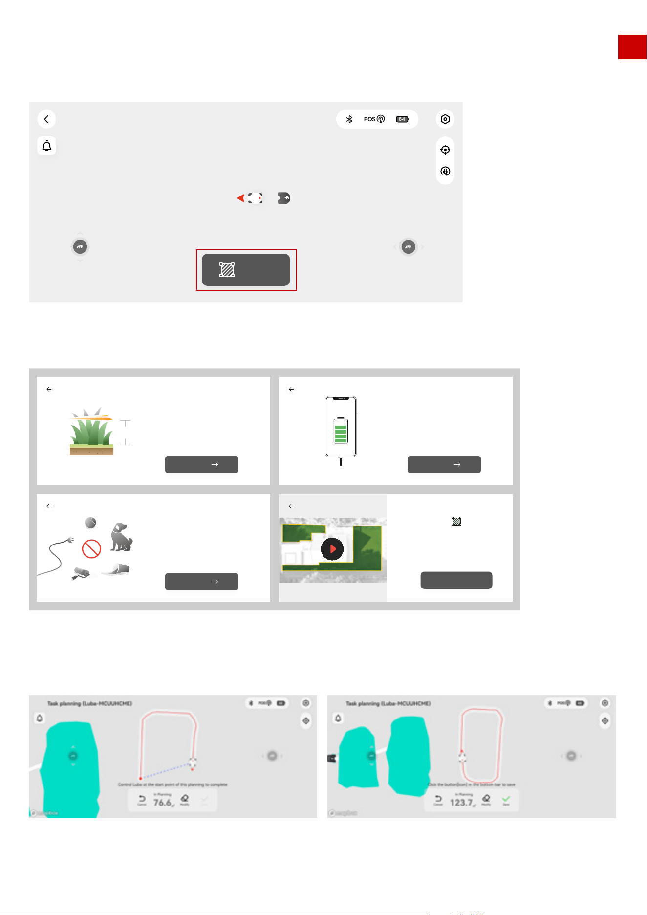
7.2 Create a task map:
1. click “Create” to start creating task map
2. Read the guidelines of creating task & working with LUBA
3. Start drawing the task area boundary
57
Create
Ready!(Luba-100020)
Make sure that before you start mowing
with LUBA,The height of grass shall not exceed 10cm
You can draw a map of 5000 square meters at most
Grass < 10CM
10CM
Next
Mobile phone charging to prevent accidental loss
of map data when the phone is out of powe
Phone power
Next
Remove toys, wires, branches, sticks
and other obstacles on the lawn,Keep children
and pets away from the lawn
Clean the lawn
Next
Delineate the area along the grassland
boundary, ensure that the distance from the
boundary is greater than 20cm,
and complete the closed area
Got it
EN
1) If “Create” clicked, this means that a task area will be created immediately, one boundary will be from
the start point to LUBA’s current location, e.g. if in the image above, the “Done” is clicked, a triangular
task area will be created.Another way to finish task creation is to manually drive LUBA back to the task
area start point. Once LUBA reaches the start point or other point on the already existing boundary then
task creation will be complete.We recommend you use this second way to finish creating the task area,
or at least click the “done” button when you are near the start point.
2) “Cancel” button, press to cancel task planning.
3)When creating a task, the “call back and auto recharge” button is unavailable. You need to cancel or
finish creating the task first
4)We highly recommend you keep a minimum 15 cm (approx.. 6 inches) from wall/fences and other
obstacles (like trees) when planning for safety reasons.
5) The user should follow LUBA within 3 m (approx. 10 feet) to ensure a good Bluetooth connection, as
well as for safety reasons.
Note:
58
3m
EN
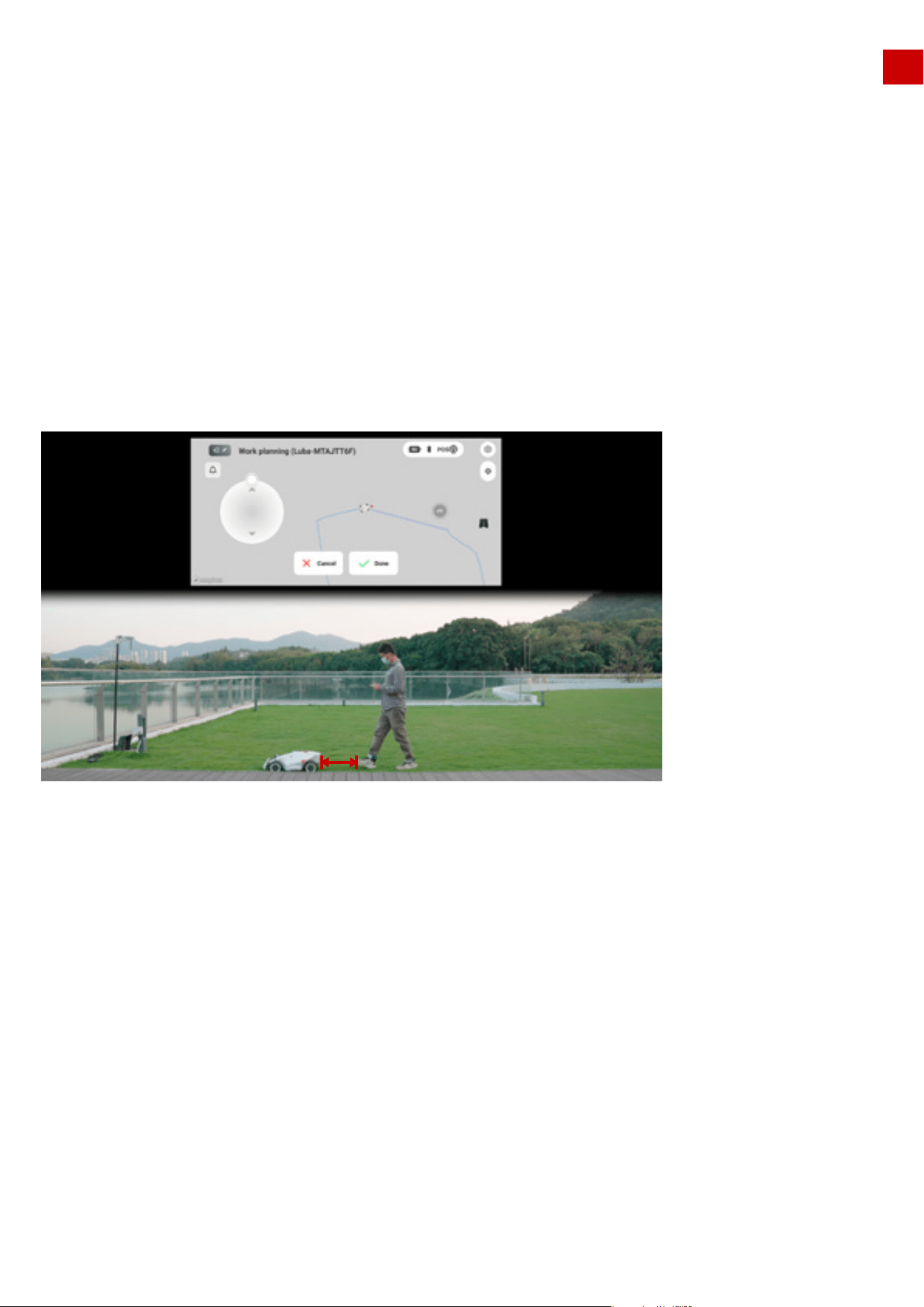
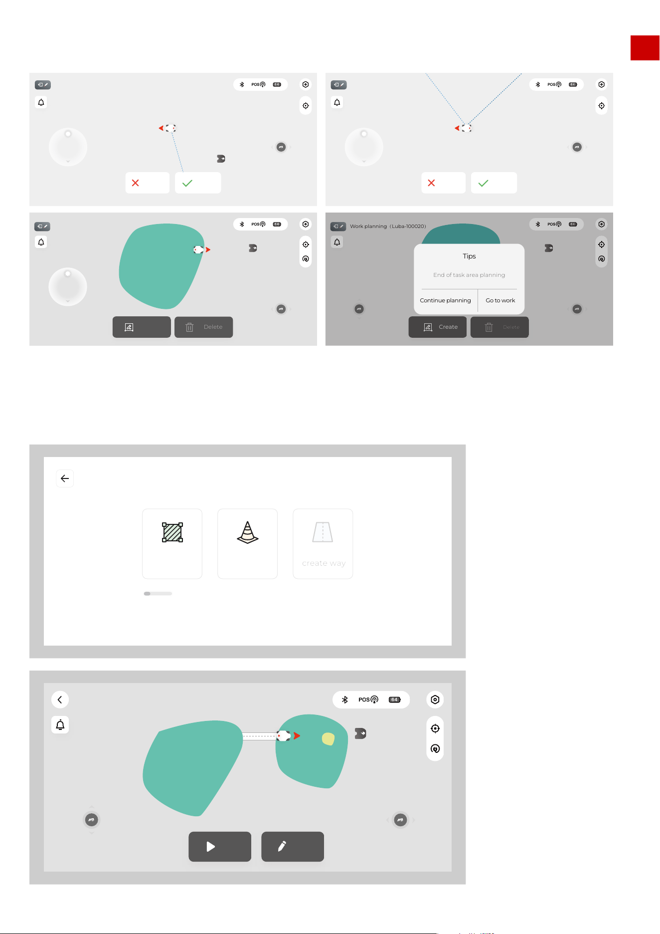
4.Finish the boundary drawing of the task area.
5.You can continue planning (add another task area in the same task, add a no-go zone, add a connec-
tion path (channel)
59
Work planning(Luba-100020)
Done
Cancel
Work planning(Luba-100020)
Done
Cancel
Work planning(Luba-100020)
Create
Delete
Work planning(Luba-100020)
Create
Delete
Continue planning
Go to work
End of task area planning
Tips
create way
ObstacleCreate task
Map size 200/3000m2
Mow Edit
Ready!(Luba-100020)
EN
You need to first drive LUBA into an already existing task area to create a connection path (channel) or a
no go zone, because they (or part of them) must be within the task area.
You first need to drive LUBA out of the already existing task area to create a new task area.
If the two task areas overlap then after creation, the overlapping part will just belong to the 1st area.
For any single task, there should be at least one connection path between the different areas
We highly recommend you set pools, flowerbeds, trees, roots, ditches and other potential permanent
obstacles/things in the lawn as no-go zones.
Note:
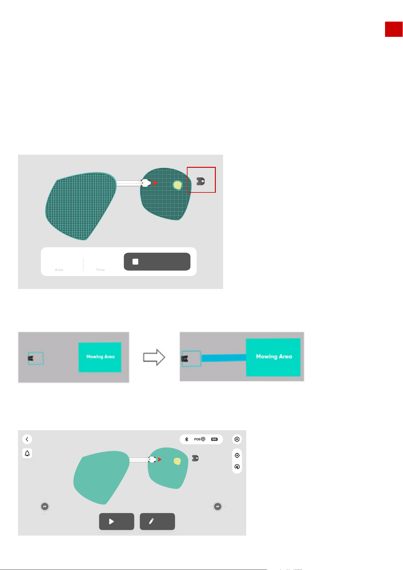
6.If the charging station is very close to one of the task areas and the “recharging area” is connected to
this task area (as shown below), there does not need to be a connection path between the task area and
charging station.
If the dotted “recharging area” is not connected to any of the task area, then a connection path (channel)
between them is needed.
7.Once all task areas, no-go zones, and connection paths are created, the task map is successfully
finished. When nothing is selected, the task map is green, as shown below:
60
Mow Edit
Ready!(Luba-100020)
Cancel Recharge
200 24
Time
Area
m
2
min
3.If the grass height is greater than 60mm, we recommend you to set the cutting height higher than
40mm, please make sure that each time you carry out mowing, only about 1/3 height of the grass is cut
(e.g. if your original grass height is 60mm, set the cutting height of LUBA 40 or 45mm; if your original
grass height is 90-100mm, set the cutting height of LUBA to 60mm.)
EN
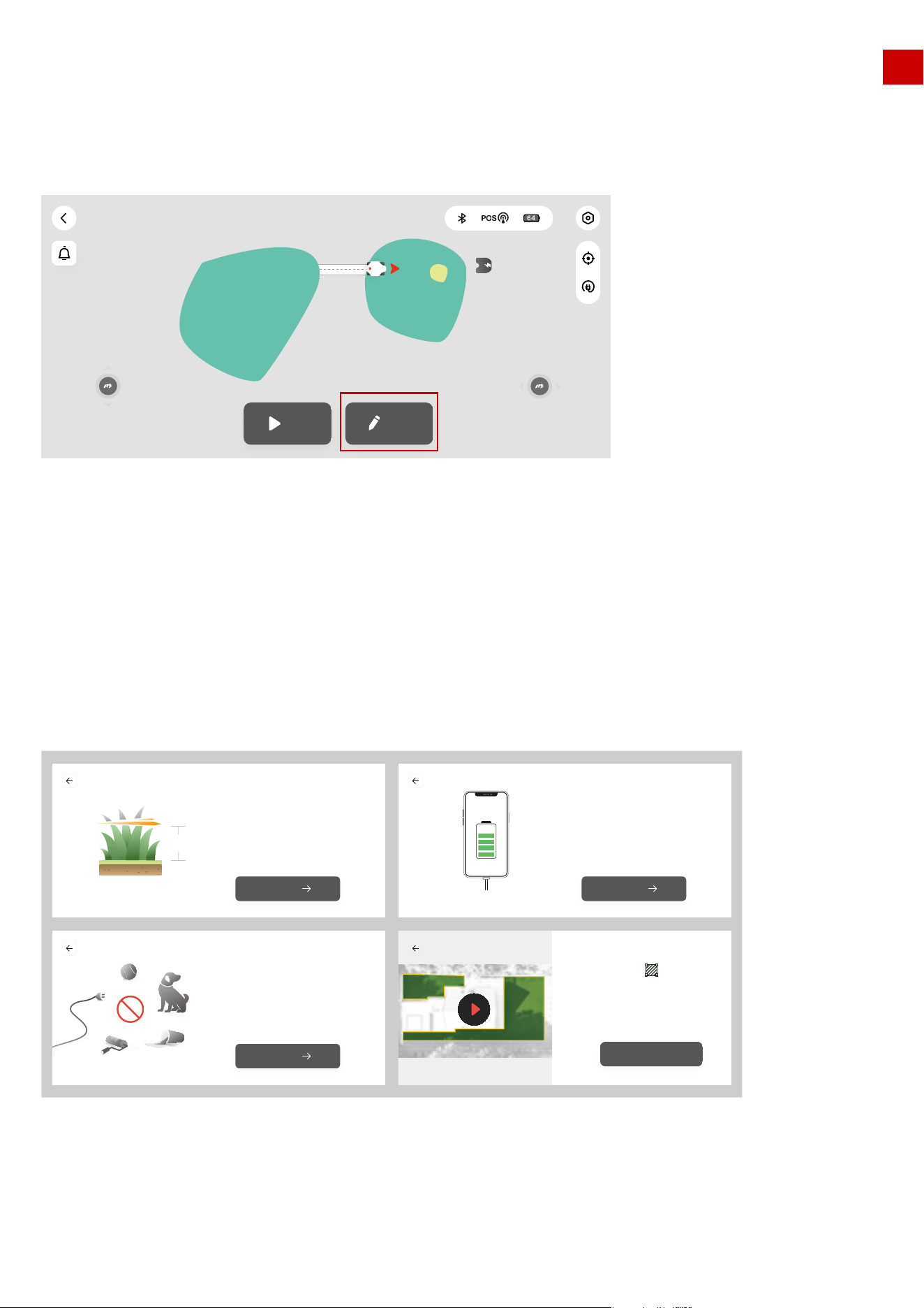
7.3 Edit the task map
1.Click “Edit” to edit the task map. Currently, you can only add areas, no-go zones, connection path to an
already existing task map, you cannot delete and change the boundary or path, but we are working on
implementing this in a future release.
2.However, you can delete the whole task map for now.
1.Make sure the height of grass in your lawn is max. 10 cm (approx. 4 inches). If the grass height in your lawn is
higher than 10 cm (approx 4 inches), please cut the grass to less than 10 cm (approx.. 4 inches) first. This is
shown in the guide below.
2.Also remember to clear items from the lawn and keep your pets and children away from LUBA when LUBA
is working.
Note:
61
Mow Edit
Ready!(Luba-100020)
Make sure that before you start mowing
with LUBA,The height of grass shall not exceed 10cm
You can draw a map of 5000 square meters at most
Grass < 10CM
10CM
Next
Mobile phone charging to prevent accidental loss
of map data when the phone is out of powe
Phone power
Next
Remove toys, wires, branches, sticks
and other obstacles on the lawn,Keep children
and pets away from the lawn
Clean the lawn
Next
Delineate the area along the grassland
boundary, ensure that the distance from the
boundary is greater than 20cm,
and complete the closed area
Got it
EN
4.If any unexpected issue occurs, press the STOP button and lock LUBA. The STOP button has the high-
est priority of any command.
5. If the lift sensor is triggered, LUBA will stop. Please press the grass cutting button and then the start
button to unlock LUBA.
6. Please mow your task area no more frequently than once a day. Too frequent mowing may do harm to
your lawn.
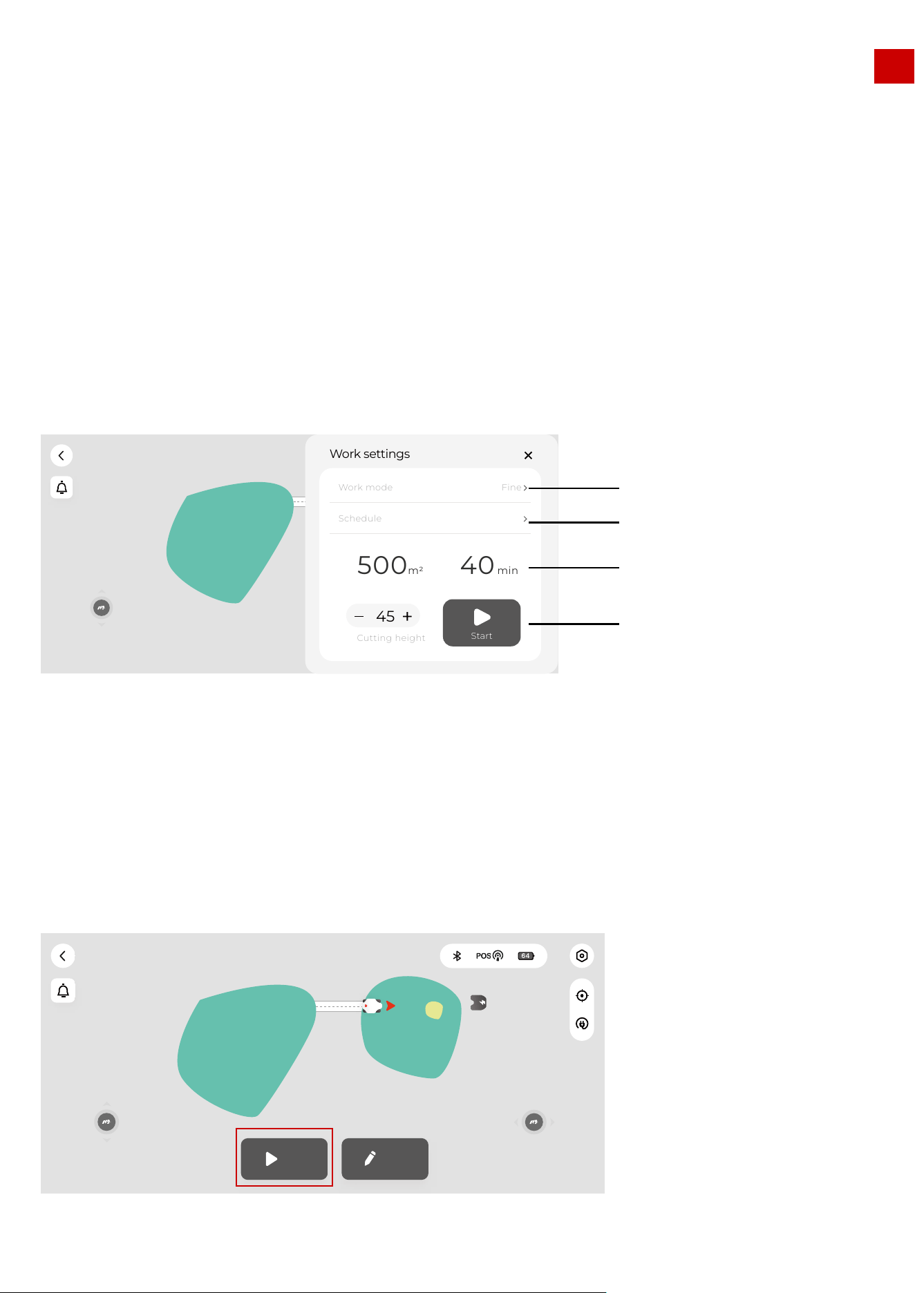
1.Once the task area is set, you can click “Mow” to set the working parameters and then start scheduling
or mowing.
8.Parameter & Schedule setting and Start Task
8.1 Work Setting interface.
8.2 Work mode settings
62
Mow Edit
Ready!(Luba-100020)
Edit
����
Work settings
500
40
min
m2
Start
Cutting height
45
Work mode
Fine
Schedule
Ready!(Luba-100020)
Work mode settings
Schedule settings
Selected area and
estimated time
Setting is done,
start working
8.Parameter & Schedule setting and Start Task
EN
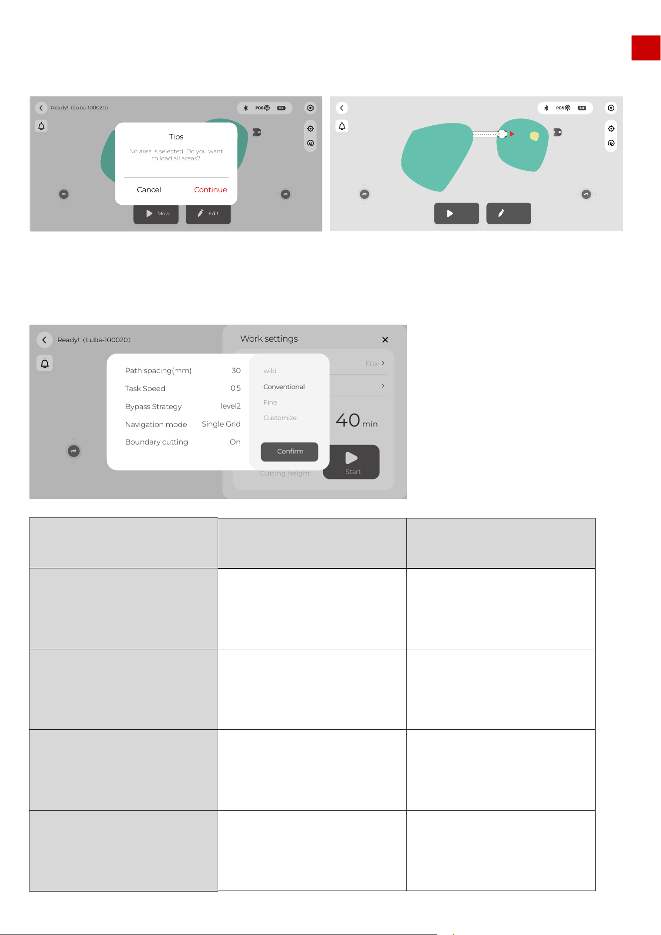
2.When setting the task parameters, you need to select at least one task area of the task map (the area
will change from green to blue when selected); if no area is selected then this results in all the areas
being loaded together:
3.The parameter settings menu for the task is as below. There are three pre-defined task modes and also
a customized mode which lets customers define each task parameter individually.
63
Mow Edit
Ready!(Luba-100020)
Mow Edit
Ready!(Luba-100020)
Cancel
Continue
No area is selected. Do you want
to load all areas?
Tips
Ready!(Luba-100020)
Edit
����
Work settings
500
m
2
40min
Start
Cutting height
45
Work mode
Fine
Schedule
Path spacing(mm)
Task Speed
Bypass Strategy
Navigation mode
Boundary cutting
wild
Conventional
Fine
Customize
30
0.5
level2
Single Grid
On
Confirm
MODE Description User case
Wild mode
Conventional mode
Fine mode
Customizes mode
Only use bumper to detect the
obstacle,because too much high grass
can disturb the detection of ultrasonic
sensor.Single grid mowing path
Cut with higher speed than fine mode,
and wider path spacing and single grid
mowing path(which means more easy
to left some grass uncut especially for
thick and dense grass).
Cut with low speed(0.3m/s) and more
narrow path spacing with double grid
mowing path.
Customer can define every task
parameter
For lawns not cut for long the height of
the grass is normally higher than
12cm;The goal of cutting is just to cut
grass down.
For normal home lawns,the cutting
result is not that fine for lawns with
strong and dense grass but with
higher effciency than Fine mode
For normal home lawns. Cut the grass
fine but with lower effciency.
For more customized use
EN
4.After click “ confirm”, the task parameter is set.
64
Options Description recommend value
Path spacing(cm)
(the unit on App is wrong)
Task speed
Bypass strategy
(the explaination on APP
is wrong, is fixing now)
Navigation mode
Boundary cutting
Path angle
The distance between 2 adjacent
mowing path. Considering our cutting
width is 40cm, if we set this to 30cm,
the overlap part between2 adjacent
mowing path would be 10cm,if no
positioning error(which is not possible)
The speed of LUBA when
mowing,lower speed gives better
result for dense and thick grass, but
with lower efficiency.
0.3-0.5
Off: bypasses the obstrucle(not set as
nogo zone) once the front bumper is
triggered(do not use ultrasonic
sensor),Level 1:slow down when
ultrasonic sensor detected some-
thing.bypasses the obstrucle(not set
as nogo zone) once the front bumper
is triggered Level 2:bypasses the
obstrucle(not set as nogo zone) once
detected by ultrasonic sensors.
OFF" is normally in wild mode.Level 1"
is normally used when there is some
high grass need to be cut in the lawn,
or when the lawn is not that flat Level
2" is normally used for flat and well cut
lawn.
single grid for more efficient
cutting.double grid for more detailed
cutting
for more open sky area at boundary,
were commend On", but if the lawn is
mostly with high walls/ buildings at
the boundary, better "off
Mowing path mode: double grid or
single grid
Cut 2 or 3 mowing path along the
boundary if it is "On”
you can change the cutting path in
different directions.
20-30
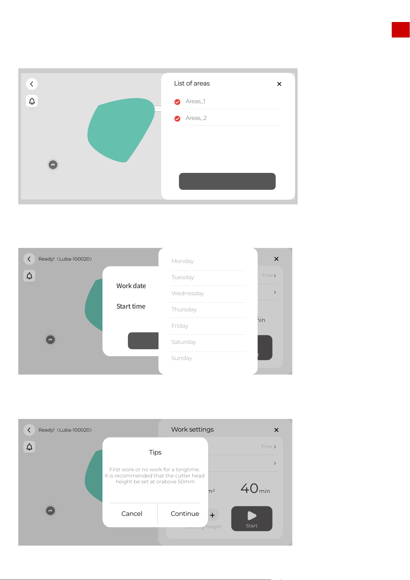
EN
1.select the area you want to set the schedule
2.set the date in each week and the start time of the selected date you want LUBA to work.
8.3 Schedule settings
3.For the first time you use LUBA, we highly recommend you to set the cutting height higher than 50mm.
65
Ready!(Luba-100020)
List of areas
Areas_1
Confirm
Areas_2
Ready!(Luba-100020)
Edit
����
Work settings
500
m
2
40
min
Start
Cutting height
45
Work mode
Fine
Schedule
Confirm
Work date
Start time
Monday
Tuesday
Wednesday
Thursday
Friday
Saturday
Sunday
Ready!(Luba-100020)
Edit
����
Work settings
500
m2 40min
Start
Cutting height
45
Work mode
Fine
Schedule
Cancel
Continue
First work or no work for a longtime.
It is recommended that the cutter head
height be set at orabove 50mm
Tips
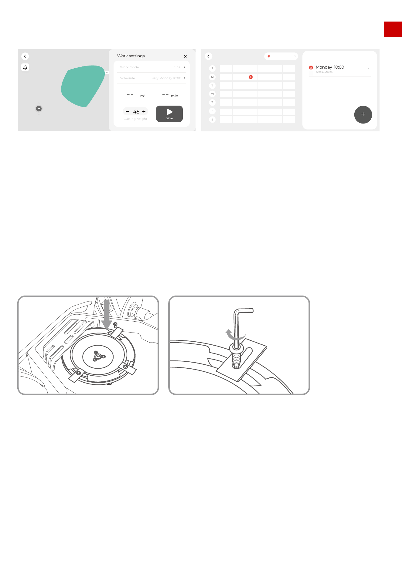
EN
9.Cutting blades replacement
4.The schedule of each task will be shown in the schedule sheet.
The cutting blades can be replaced when they are damaged or worn out. We recommend you change the
blades every six months.
Tools needed:M2.5 Allen Key.
The LUBA MUST BE TURNED OFF when replacing, inspecting, or cleaning the cutting blades.
Make sure the blades are fixed securely and flexibly.
1.All the cutting blades are recommended to be replaced at the same time when the mowing result
does not look as good as the previous performance.
2.The blades are recommended to be replaced every three months or 150hours of mowing. For some
thick grass, the cutting blade may need to be replaced more frequently.
Note:
66
Ready!(Luba-100020)
Edit
����
Work settings
--
m2
--
min
Save
Cutting height
45
Work mode
Fine
Schedule
Every Monday 10:00
S
W
S
M
T
T
F
Luba-100020
0:00 4:00 8:00 12:00 16:00 20:00 24:00
Monday 10:00
Areas0, Areas1
+

EN
Specifications
Lawn Size
Engine
Max Climbing Ability
Vertical Obstacle Passing Ability
Cutting Height
Cutting Width
Area Capacity Per Hour, Max
Battery Capacity
Typical Charging Time
Mowing Time on One Charge
Charging system
Battery Type
Virtual Boundary
Auto-Navigation
Planned Cuting Route
Max Zone Management
Obstacle Detection and Avoidance
No-go Zone
Rain Sensor
Connectivity
User Interface
Mowing Schedule
Firmware Update
GPS Anti-Theft
Lift Sensor
Tilt Sensor
Waterproof Level
Noise Level
LUBA AWD 5000
up to 5000m
2
(1.25 acres)
All-Wheel Drive(AWD)
75% Slope(37%)
50 mm
30-70 mm(1.2-2.8 in.)
400mm (15.7 in.)
500m2(5381 ft2)
10 Ah
150 Minutes
3 Hours
Automatic
Lithium-ion
Yes
Yes
3 Modes
10
Yes
Yes
Yes
Bluetooth®, Wi-Fi
Mammotion App
Yes
FOTA
Yes
Yes
Yes
IPX6
60 dB
LUBA AWD 3000
up to 3000m
2
(0.75 acre)
All-Wheel Drive(AWD)
65% Slope(33%)
50 mm
30-70 mm(1.2-2.8 in.)
400mm (15.7 in.)
350m2(3767 ft2)
10 Ah
150 Minutes
3 Hours
Automatic
Lithium-ion
Yes
Yes
3 Modes
6
Yes
Yes
Yes
Bluetooth®, Wi-Fi
Mammotion App
Yes
FOTA
Yes
Yes
Yes
IPX6
60 dB
LUBA AWD 1000
up to 1000m
2
(0.25 acre)
All-Wheel Drive(AWD)
65% Slope(33%)
50 mm
30-70 mm(1.2-2.8 in.)
400mm (15.7 in.)
350m2(3767 ft2)
4.5 Ah
90 Minutes
2 Hours
Automatic
Lithium-ion
Yes
Yes
3 Modes
3
Yes
Yes
Yes
Bluetooth®, Wi-Fi
Mammotion App
Yes
FOTA
Yes
Yes
Yes
IPX6
60 dB
10. Specifications:
67
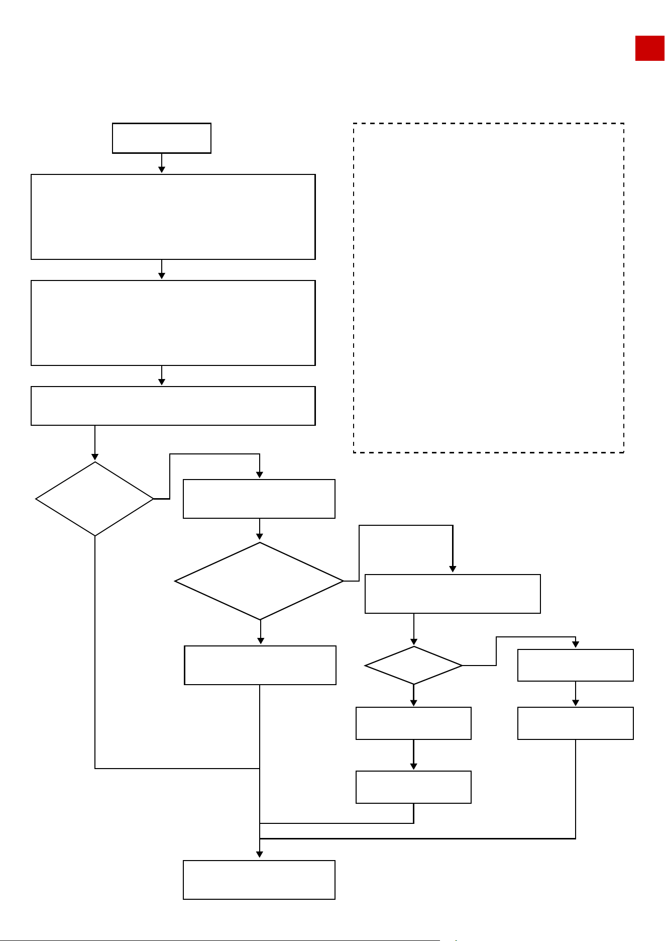
EN
11. Aftersales Policy:
Issue Report
Information Gathering
1. Product’s SN *1
2. Purchasing invoice or receipt attached
3. Fill in the service form
4. Video or pictures of malfunction issues attached
Contact Mammotion or Local Service Center*2
Mammotion contact information:
1. Email ([email protected])
2. Call us at +86-18588403621 or local 400/800 hotline*3
Remote Technical Support
Pre-diagnose and Trouble Shooting
Note:
Send product to Local
Service Center or Dealers *4
Forward Estimated Repair Quotation
(Materials + Labor + Shipping)
Payment Received
Forward Estimated
Shipping Cost
Payment Received
Repair or Replacement
Repair or Replacing for free
Deliver to Customer
Case Closed
Can be
Resolved
Remotely
verify if the product
or issue Complies
with Warranty Policy
Agree to pay
1. SN is on the sticker on machine body.
Forexample, ***-2238****-S/N.
2. Service Center Contact Information:
Contact [email protected]om for
details.
3. Mammotion business hours, Monday to
Friday 9:30 a.m. to 6:30 p.m.
4. Customer is responsible for shipping
and customs costs when sending
product(s) for replace, repair, or diagnose,
Mammotion will bear the cost of repairs
and shipping back if diagnose result as
warranty case.
5. Commercial Invoice is necessary for
international shipping.
6. More detailed information Please check
on the Mammotion After Sales Policy.
YES
YES
YES
NO
NO
NO
11.1 Cuetomer services flow
68

EN
11.2 Part I - limted Warranty
These MAMMOTION After-Sales Policies (these “Policies”) only apply to MAMMOTION products you
purchased from MAMMOTION authorized retailers or MAMMOTION directly for your own use and not for
resale.
By using your MAMMOTION product, you agree to be bound by these Policies. If you are not eligible or
do not agree to any of the Terms, do not use your MAMMOTION product.
When receiving service, MAMMOTION is responsible for loss or damage to your product only while it is in
MAMMOTION's possession or in transit, if MAMMOTION is responsible for transportation.
MAMMOTION is not responsible for loss or disclosure of any data, including confidential information,
proprietary information, or personal information, contained in a product.
11.3 Part II – Warranty
Under this Limited Warranty, MAMMOTION warrants that each MAMMOTION product that you purchase
will be free from material and workmanship defects under normal use in accordance with MAMMOTION’s
published product materials during the warranty period. MAMMOTION’s published product materials
include, but are not limited to user manuals, quick start guide, maintenance, specifications, disclaim, and
in-app notifications.The warranty period varies for different products and parts. Please check in below
table to verify the duration of the warranty for your particular product or parts.
MAMMOTION will attempt to diagnose and resolve your problem by telephone, e-mail or online chat.
MAMMOTION may direct you to download or install particular software updates. If your problem cannot
be resolved over the telephone or through the application of software updates, you may be required to
deliver the product to MAMMOTION for further examination or to MAMMOTION’s locally appointed
service centers.
What Will MAMMOTION Do
All the damages caused by misuse or not following the user manual and below:
1) Third party claims against you for damages
2) Loss, damage or disclosure of your data
3) Special, incidental, punitive, indirect or consequential damages, including but not limited to lost
profits, business revenue, goodwill or anticipated savings. In no case should the total liability of MAMMO-
TION, its affiliates, suppliers, resellers, or service providers for damages from any cause exceed the
amount of actual direct damages, not to exceed the amount paid for the product.
What This Limited Warranty Does NOT Cover
When after-sales service involves the replacement of a product or part, the replaced product or part
becomes MAMMOTION’s property and the replacement product or part becomes your property. Only
unaltered MAMMOTION products and parts are eligible for replacement.
Replacement products or parts provided by MAMMOTION may not be new, but it will be in good work-
ing order and at least functionally equivalent to the original product or part’s warranty.
A replacement product or part shall be covered for the time remaining in the original product’s warranty.
Product and Part Replacement
69

EN
1.The warranty period for a product starts on the day such products are delivered.
2.If you cannot provide an invoice or other valid proof of purchase, then the warranty period will begin 90
days after the production date shown on the product, unless otherwise agreed upon between you and
MAMMOTION.
3.MAMMOTION will need users to arrange the shipment by themselves if users would like to send the
products to local service center or MAMMOTION factory for further diagnosis. MAMMOTION will repair or
replace and send back to users at no cost if the problem falls under this Limited Warranty. If not, MAM-
MOTION or designated service center may charge a fee accordingly.
4.MAMMOTION guarantees that, subject to the following conditions, Warranty Repair Service can be
requested. Please contact MAMMOTION or your authorized MAMMOTION dealer for more details. You
will be required to fill out a repair form or RMA (Return Material Approval), which should be sent to us
along with the to-be-repaired unit.
5.DOA (dead-on-arrival, defective-on-arrival, and/or damaged-on-arrival), refers to goods that are defec-
tive on arrival. After receiving goods from MAMMOTION, or the authorized dealer, if the product appears
to be damaged or has performance failure(s), please contact MAMMOTION or your authorized MAMMO-
TION dealer to identify and confirm if a replacement is needed.
6.Replacement applies to DOA cases. It should be requested within 7 calendar days of receiving the
goods. The replacement will be completed within 30 calendar days upon receipt of the completed
goods, including all original accessories, attachments and packaging.
RMA (Return Material Approval), please fill out the form provided by MAMMOTION, Scan and Email to
1.Follow the procedures specified by MAMMOTION as shown in the “MAMMOTION General Customer
Services Flow” part. Backup all data contained on your product by yourself.
2.Except for drive logs, remove all data, including confidential information, proprietary information, and
personal information from the product. Or, if you are unable to remove any such information, modify the
information to prevent its access by other party so that it is not personal data under applicable law.
MAMMOTION shall not be responsible for the loss or disclosure of any data, including confidential infor-
mation, proprietary information, or personal information, on a product returned or accessed for warranty
service.
3.Provide MAMMOTION with all system passwords, if necessary. Provide MAMMOTION with sufficient and
safe access to your product, so MAMMOTION can provide service as needed.
4.Remove all additional parts, alterations, and attachments not covered under warranty.
5.Ensure that the product or part is free of any legal restrictions that prevent its replacement.
If you are not the owner of a product or part, obtain authorization from the owner for MAMMOTION to
provide warranty service.
What to do Before Obtaining After-sales Service
If a product does not function as warranted during the warranty period, you may obtain after-sales
service by contacting MAMMOTION’s local dealer or through suppor[email protected]. You will need
to provide valid proof of purchase, receipt or order number (for MAMMOTION Direct Sales) along with
the serial number of your products for the warranty service. Charges may apply for services not covered
by this Limited Warranty. Please contact MAMMOTION for information specific to your location.
Please note that the warranty service is only available in the respective MAMMOTION service regions
where you purchased your MAMMOTION product.
12.How to Obtain Warranty Service
70
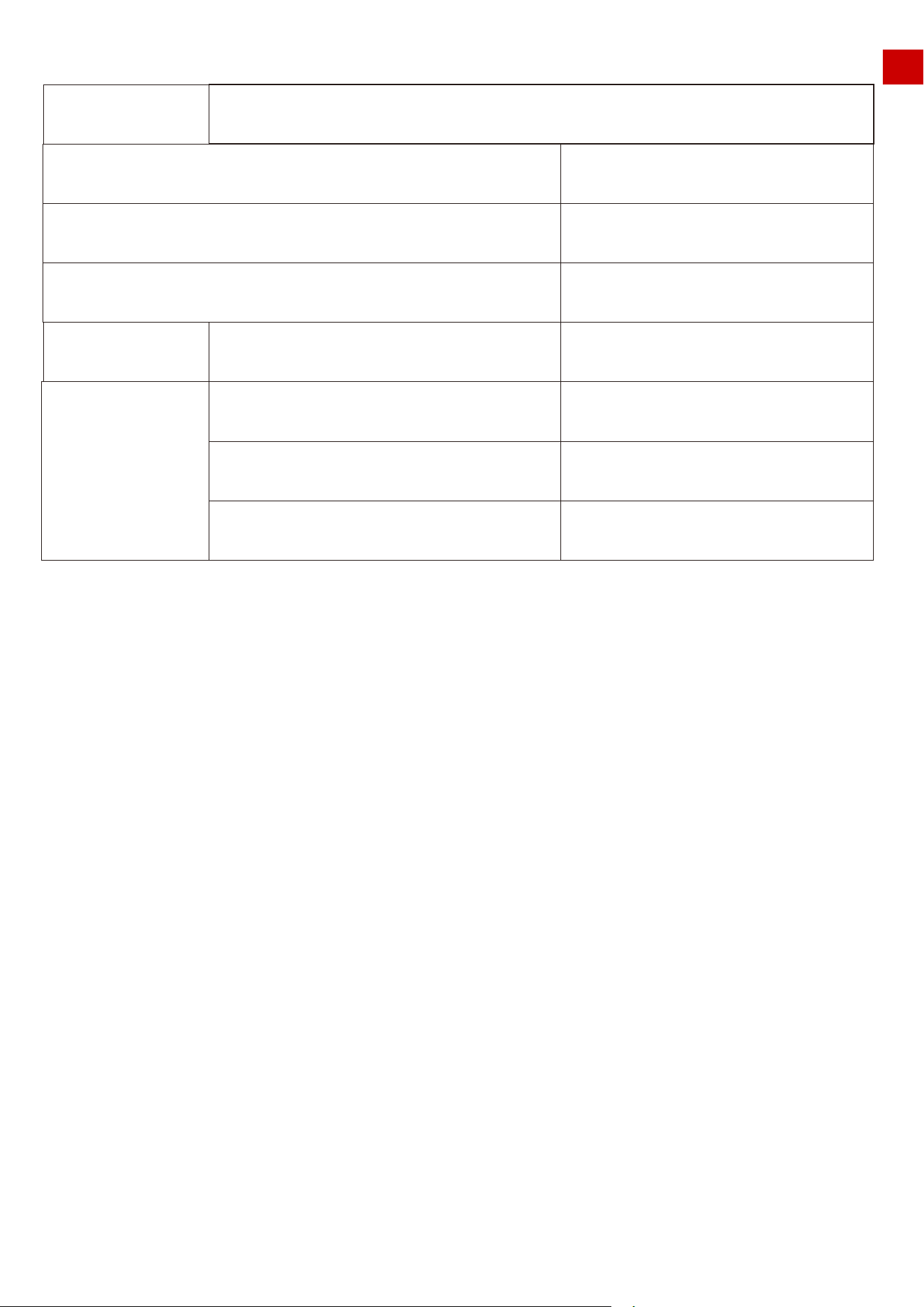
EN
Table for parts warranty:
*MAMMOTION reserves the rights of interpretation for this Limited Warranty and may not be able to notify
each user when updates happen. Refer to the official website for any details and updates.
Your Other Rights
This Limited Warranty provides you with extra and specific legal rights. You may have other rights according
to the applicable laws of your state or jurisdiction. You may also have other rights under a written agreement
with MAMMOTION. Nothing in this Limited Warranty affects your statutory rights, including the rights of
consumers under laws or regulations governing the sale of consumer products that cannot be waived or
limited by agreement.
Model
Component
Main body
Battery
Accessories
Charging station &RTK antenna
Limited warranty period
2 years
2 years
1 years
No warranty
No warranty
No warranty
Tire
Decoration/Appearance parts
Cutting blade
Wearing parts
LUBA
71

EN
1.Motors and cutting blades maintenance (After Every Mowing task)
In order to have your LUBA in a good condition at all time, please clean your LUBA each time after
mowing. The cleaning process in MAMMOTION user manual instructs you to get rid of the clippings,
twigs, leaves or dust and keep the mower in good condition.
1.1 Turn off the mower and flip it over on a relatively soft surface ground. Then find a tool to clean the
clippings, twigs or leaves from the bottom of mower. Make sure the cutting blade disks are clean and will
not get stuck.
1.2 If the mower is to be stored for a long time, it will be better to add anti-rust oil on the cutting blades
after cleaning.
1.3 Keep the hub motors shaft dry and clean for long-term storage.
1.4 The cutting blades are recommended to be replaced every 3 months or 150hours mowing.
2.Battery Maintenance
2.1 Keep 50% to 60% battery level before long term storage.
2.2 Charge to full once every 90 days.
2.3 Clean and make sure the charging ports on the mower are dry and clean after very
mowing task.
3.Appearance maintenance (After Every Mowing task)
1.1 Clean the cover and the wheels with fresh water and make sure there are no clippings or dust cover-
ing on it.
1.2 When there is damage on it, please replace the broken parts as possible.
4.Replace Blades
1.1 If the mower is used on a regular basis, it is recommended to replace the blades and screws every
50-100 hrs to ensure safety and better mowing results. Replace all blades and their screws at the same
time for a safe cutting system.
1.2 Wear heavy gloves when you inspect or replace the blade.
1.3 Only use the right type of screws and original blades as approved by Mammotion.
1.4 DO NOT reuse the screws. Doing so can cause serious injury.
We provide customers with after-sale services, excluding the following circumstances:
1.Crashes damage caused by non-manufacturing factors, including but not limited to, user errors.
2.Damage caused by unauthorized modification, disassembly, or shell opening not in accordance with
official instructions or manuals.
3.Damage caused by improper installation, incorrect use, or operation not in accordance with official
instructions or manuals.
4.Damage caused by a non-authorized service provider.
5.Damage caused by unauthorized modification of circuits and/or mismatch or misuse of the battery
and charger.
6.Damage caused by users who do not follow instructions and manual recommendations.
14.Disclaimer
13.Maintenance Guide
72

EN
7.Damage caused by operation in bad lawn conditions (i.e. large areas of puddle without setting
no-go-zones, a lot of stones covering on it, etc.)
8.Damage caused by operating the product in an environment with electromagnetic interference (i.e., in
mining areas or close to radio transmission towers, high-voltage wires, substations, etc.).
9.Damage caused by operating the product in an environment suffering from interference from other
wireless devices (i.e. transmitter, video-downlink, Wi-Fi signals, etc.).
10.Damage caused by reliability or compatibility issues when using unauthorized third-party parts.
11.Damage caused by operating the unit with a low-charged or defective battery.
12.Loss of, or damage to, your data by a product.
13.Any software program, whether provided with the product or installed subsequently.
14.Failure of, or damage caused by, any third-party products, including those that MAMMOTION may
provide or integrate into the MAMMOTION product at your request.
15.Damage resulting from any non-MAMMOTION technical or other support, such as assistance with
“how-to” questions or inaccurate product set-up, installation, and firmware upgrade.
16.Damage caused by operating the MOWER in the sensitive zone (military, natural resource protection
zoning, etc.)
17.Damage caused by unpredictable factors (cars, wild animal attacks, flood, etc.)
18.Products or parts with an altered identification label or from which the identification label has been
removed.
For more information, please check our website for tuition videos, or read FAQ in MAMMOTION
APP/Help/FAQ.
https://MAMMOTION.com/
This content is subject to change without prior notice.
73