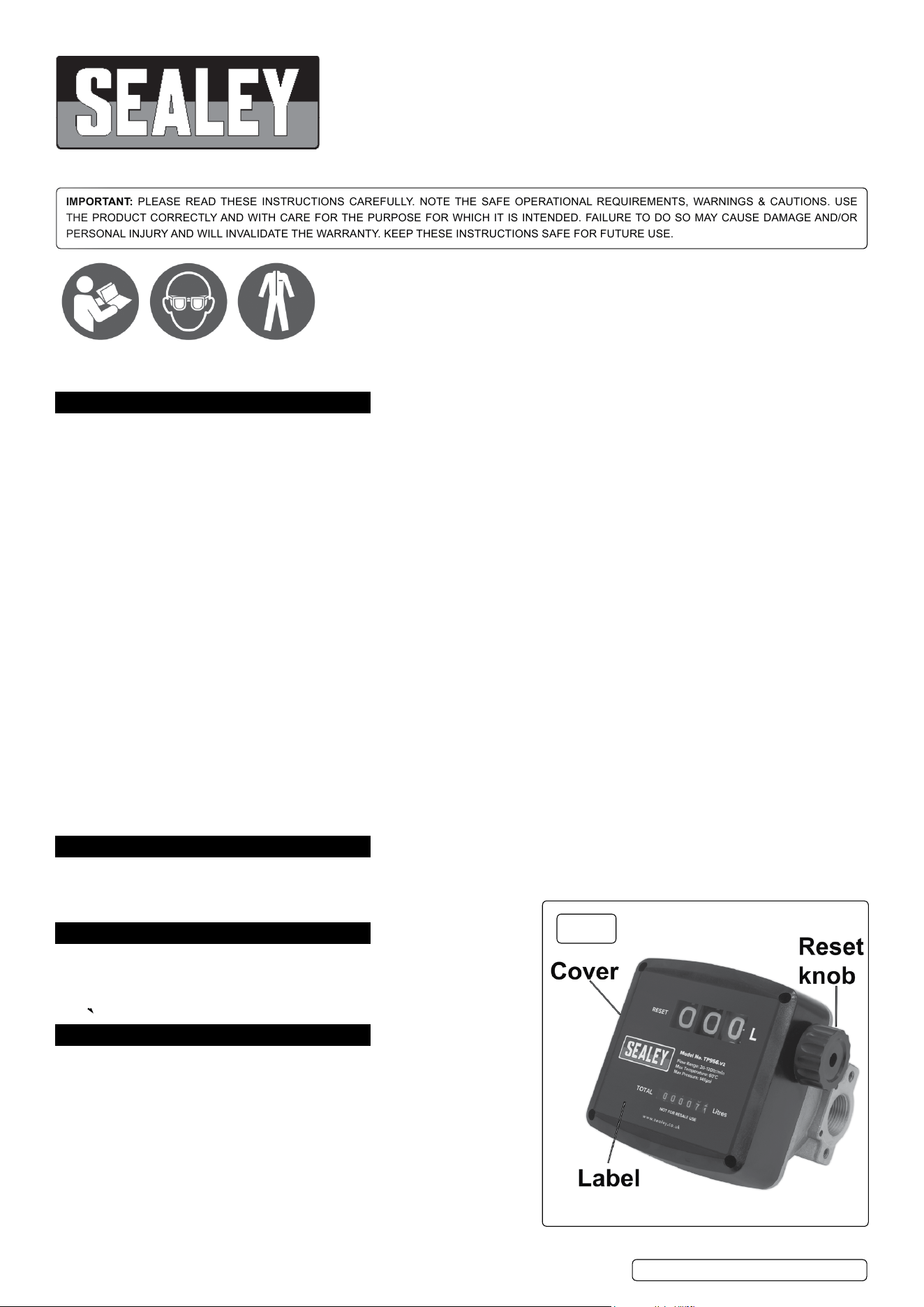
dIESEL & FLUId FLOW METER
MODEL NO: TP956.V2
Thank you for purchasing a Sealey product. Manufactured to a high standard, this product will, if used according to these instructions,
and properly maintained, give you years of trouble free performance.
IMPORTANT: PLEASE READ THESE INSTRUCTIONS CAREFULLY. NOTE THE SAFE OPERATIONAL REQUIREMENTS, WARNINGS & CAUTIONS. USE
THE PRODUCT CORRECTLY AND WITH CARE FOR THE PURPOSE FOR WHICH IT IS INTENDED. FAILURE TO DO SO MAY CAUSE DAMAGE AND/OR
PERSONAL INJURY AND WILL INVALIDATE THE WARRANTY. KEEP THESE INSTRUCTIONS SAFE FOR FUTURE USE.
1. SAFETY
WARNING! Ensure health & safety, local authority, and general workshop practice regulations are strictly adhered to when using this
equipment.
9 Familiarise yourself with product application and limitations, as well as the specific potential hazards peculiar to this product.
9 Maintain the meter in good condition (use an authorised service agent).
9 Replace or repair damaged parts. Use genuine parts only. Non authorised parts will invalidate the warranty.
9 Use only to meter diesel fuel and oils.
9 Ensure safety eye protection and protective clothing are worn when using this product.
9 Keep the work area clean, uncluttered and ensure there is adequate lighting.
9 Maintain correct balance and footing. Ensure the floor is not slippery and wear non slip shoes.
9 Keep children and unauthorised persons away from the working area.
9 After use, drain any fluids from the equipment before storage.
9 Dispose of waste liquids in accordance with local authority regulations.
8 dO NOT exceed the maximum pressure of 145psi (10bar).
8 dO NOT use the equipment near open flames.
8 dO NOT smoke whilst using this equipment.
8 dO NOT use for corrosive fluids.
8 dO NOT dismantle, tamper with or adapt the equipment for any purpose other than for which it is designed.
8 dO NOT use the unit if it has been dropped or mishandled, check the unit to ensure there is no damage.
8 dO NOT use taper connections, use parallel connectors only.
8 dO NOT use compressed air on the turbine, the excessive rotation will damage the unit.
9 Keep the meter clean and store in a safe dry, childproof location.
WARNING! dO NOT allow uncontrolled discharge of fluids thus polluting the environment. All liquids must be disposed of according to
local authority regulations.
WARNING! The correct working of the nutating disk may be affected if solid particles enter the measuring chamber. Always lter the
uid by installing a lter on the meter inlet.
2. INTROdUcTION
Volumetric nutating disc meter with three digit resettable batch display and six digit cumulative total display. Unique lter and ange
assembly allows meter to be positioned in four congurations. Suitable replacement meter for Model no. TP955 Diesel/Fluid
Transfer System.
3. SPEcIFIcATION
Model No. ............................................................... TP956.V2
Flow Rate .......................................................... 20-120ltr/min
Weight ........................................................................... 1.8kg
Max. Working Pressure ................................... 145psi (10bar)
4. INSTALLATION
NOTE: Numbers refer to Parts Diagram section 9.
4.1. The meter can be installed in any position, on rigid pipelines or exible
hoses, directly on pumps or tanks. The meter ow direction is xed and
indicated by an arrow on the outlet.
4.2. Meter cover (3) can be removed and the Register base (8), along with
Meter Unit (6), can be rotated at every 90° orientation in four different
positions.
NOTE: The rear of the meter body is equipped with 4 blind holes which
can be threaded (M5) for a mounting.
4.3. HOW TO ROTATE THE dISPLAY
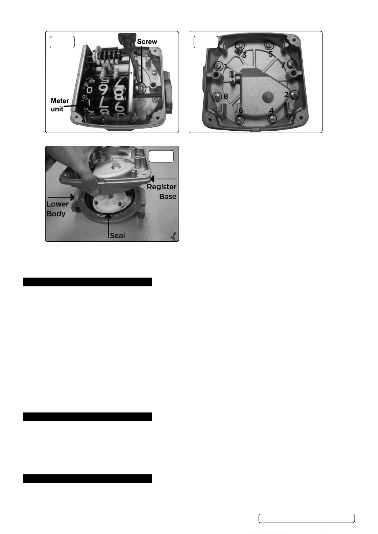
4.3.1. Remove the four retaining screws (5) and lift up the meter cover (3), g.1.
4.3.2. Loosen the 2 screws, see g.2, on both sides and separate the meter unit (6) from the register base (8).
Refer to
instruction
manual
Wear eye
protection
Wear protective
clothing
TP956.V2 | Issue:1 15/10/18
Original Language Version
© Jack Sealey Limited
fig.
1
Original Language Version
© Jack Sealey Limited
4.3.3. Loosen the 8 screws in the sequence shown in g.3.
4.3.4. Remove the register base (8) together with the gear unit (9). Take care to NOT damage the seal (14), g.4.
4.3.5. Rotate the register base (8) to the desired position. The display can be placed in the 4 positions. Tighten the base screws (7) and ret
the meter unit (6) to the new position. Make sure that the Total gears are moving smoothly.
4.3.6. Ret the meter cover (3) and x the meter label (1). Fix the Reset Knob (2) by pushing it rmly on to the reset shaft, g.1.
5. cALIbRATION
5.1. The meter is pre-calibrated in the factory under standard conditions. A new calibration is necessary whenever:
- the meter is disassembled for maintenance
- the media used is different from diesel oil.
5.2. cALIbRATION
5.2.1. Remove the plug and seal (17).
5.2.2. Vent the air from pump, pipelines and meter by dispensing until the ow stream is full and steady.
5.2.3. Stop the ow by shutting off the nozzle, but let the pump run.
5.2.4. Reset the batch total using reset knob (2).
5.2.5. Dispense at the desired ow rate into a graduated container whose capacity should not be lower than 20 litres (5 gallons).
NOTE: DO NOT reduce the ow in order to reach the preset value of the calibration container. The right method is to start and
stop the full ow repeatedly until the required level is maintained.
5.2.6. The Meter Value should be matched with the Container Value as given below:
- If the Meter Value is higher than Container Value, loosen the calibration screw (16).
- If the Meter Value is lower than the Container Value, tighten the calibration screw (16).
5.2.7. Repeat steps until accuracy is satisfactory.
5.2.8. Tighten the plug with seal (17) again.
NOTE: Always x the plug with seal (17) to avoid leakage because the O ring on the calibration screw (16) does not have any sealing
function. (The O ring in this case only avoids accidental loosening of calibration screw).
6. OPERATION
6.1. After installation, turn the rest knob (2) until the batch total is completely reset. The totaliser can not be reset in any way.
6.2. USE bY GRAVITY
6.2.1. The meter can be used without pump pressure in a system where ow is generated due to difference in height between fuel level and
dispensing point.
6.2.2. Use by gravity is not recommended where the height of the fuel is lower than 4 feet as the ow rate will be reduced, resulting in
inaccurate measurement.
6.2.3. In eld calibration is always advisable in case of gravity installations.
7. MAINTENANcE
WARNING! Before disassembling always make sure the line pressure is released and all uid is drained from the meter.
7.1. The meter does not require any special maintenance other than cleaning of the measuring chamber, (it may get clogged due to
insufcient ltration).
fig.
2
fig.
3
fig.
4
TP956.V2 | Issue:1 15/10/18
Original Language Version
© Jack Sealey Limited
NOTE: The meter can be easily disassembled into its main parts without removing the body from the pipes:
- Never remove meter label from the meter.
- Cleaning is done with a soft brush or small tool (i.e. a screwdriver).
- During cleaning, be careful not to damage the measuring chamber or nutating disk.
- A new calibration is always necessary after disassembling the measuring chamber.
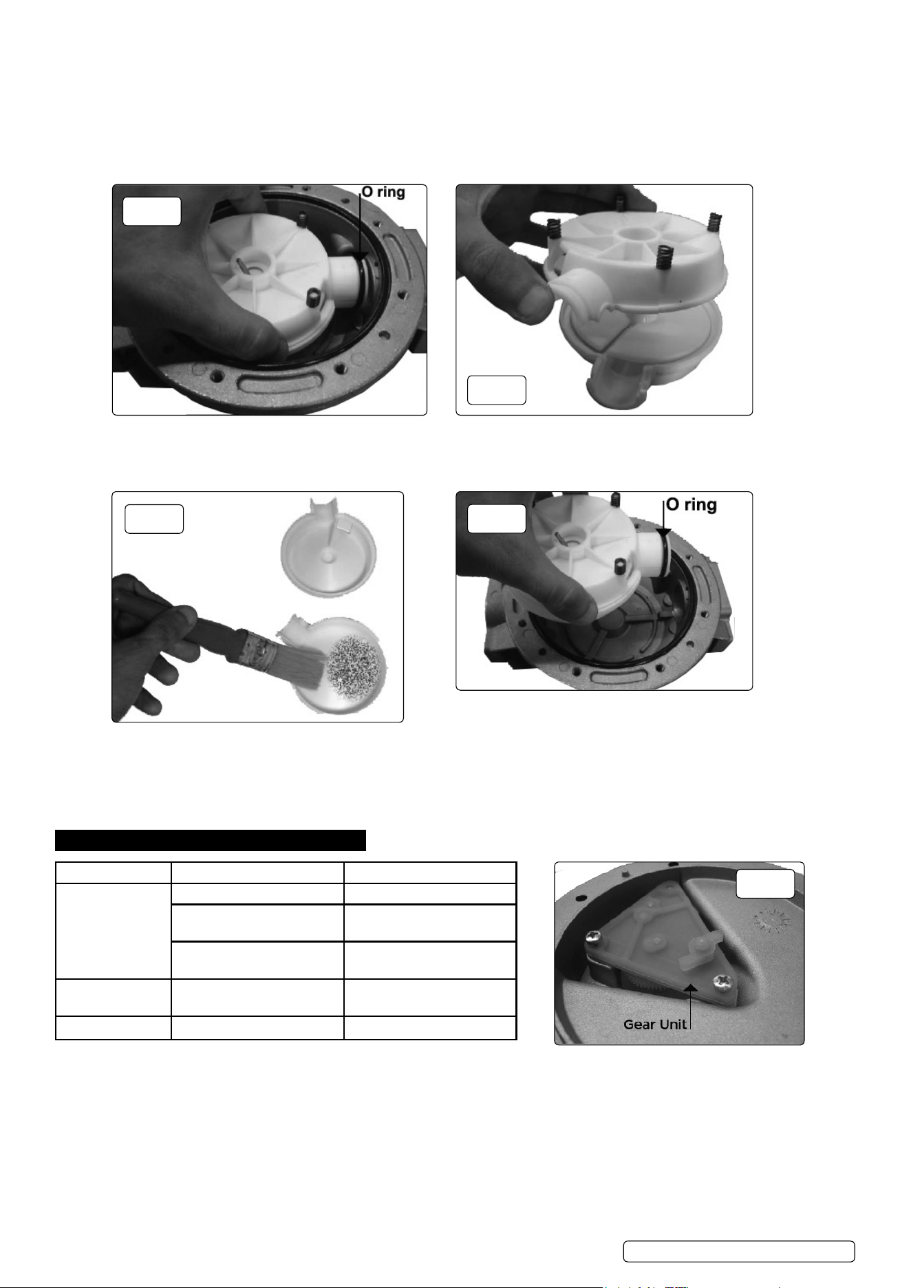
7.2. cLEANING OF THE MEASURING cHAMbER
7.2.1. Remove the knob (2) by pulling it axially outwards. Remove Meter cover, Meter unit and Register base by following steps 4.3.1 to 4.3.4
from the section 4.3 ‘How to rotate the display’.
7.2.2. Remove the whole measuring chamber (13) by lifting it from the lower body (15) and at the same time pulling it back towards the inlet
in order to remove the O ring from its seat, g.5.
7.2.3. To check the inside of the measuring chamber (13) remove the O ring (g.5).
7.2.4. Divide the two half chambers (10 and 12) containing the nutating disk (11) (g.6).
7.2.5. Use a soft brush or a small tool (i.e a screwdriver) to clean the measuring chamber. Be careful not to damage the chamber or the disk,
g.7.
7.2.6. To reassemble reverse the described procedure paying particular attention to lubricating the Seal (14) and O ring before installation,
g.8.
7.2.7. Check the gear unit (9) can rotate freely before xing the cover, g.9.
7.2.8. Recalibrate the meter as mentioned in section 5 Calibration.
8. TROUbLESHOOTING
fig.
5
fig.
6
fig.
7
fig.
8
fig.
9
TP956.V2 | Issue:1 15/10/18
Problem Cause Solution
Poor accuracy Wrong calibration Recalibration see section 5
Soiled or blocked meauring
chamber
Clean measuring chamber,
see section 7.2
Air in the uid Locate and eliminate leaks
in inlet lines
Reduced ow rate Clogged measuring chamber Clean measuring chamber,
see section 7.2
Blocked or soiled lter Clean the lter
Sealey Group, Kempson Way, Suffolk business Park, bury St Edmunds, Suffolk. IP32 7AR
01284 757500 01284 703534 sales@sealey.co.uk www.sealey.co.uk
ENVIRONMENT PROTEcTION
Recycle unwanted materials instead of disposing of them as waste. All tools, accessories and packaging should be sorted, taken to
a recycling centre and disposed of in a manner which is compatible with the environment. When the product becomes completely
unserviceable and requires disposal, drain any fluids (if applicable) into approved containers and dispose of the product and fluids
according to local regulations.
Note: It is our policy to continually improve products and as such we reserve the right to alter data, specifications and component parts without prior
notice.
Important: No Liability is accepted for incorrect use of this product.
Warranty: Guarantee is 12 months from purchase date, proof of which is required for any claim.
Parts support is available for this product. Please email sales@sealey.co.uk or telephone 01284 757500
Original Language Version
© Jack Sealey Limited
TP956.V2 | Issue:1 15/10/18
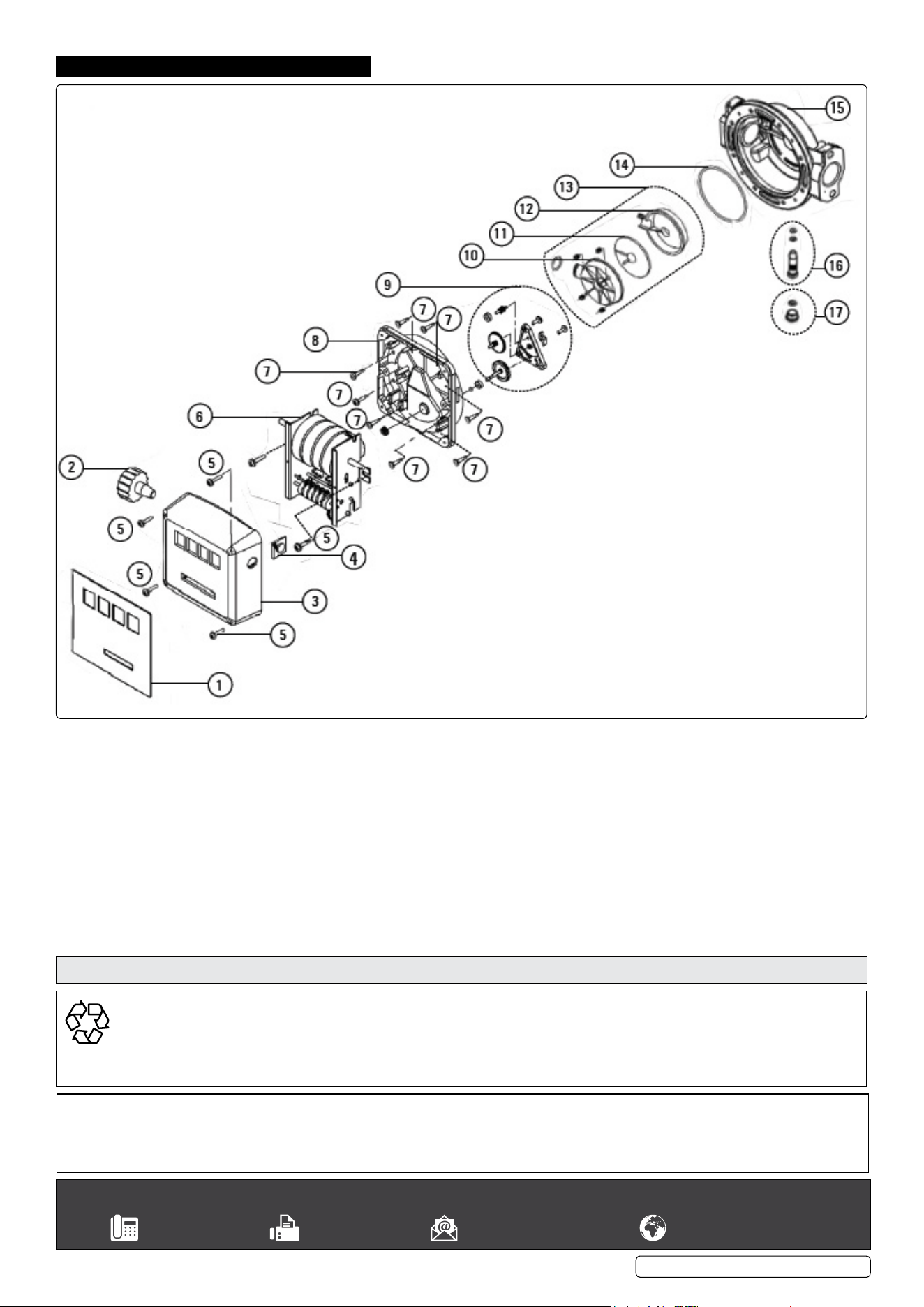
9. PARTS dIAGRAM
.
1 Meter label
2 Reset knob
3 Meter cover
4 Knob plug
5 Screw
6 Meter unit
7 Screw
8 Register base
9 Gear unit
10 Upper half chamber
11 Nutating disc
12 Lower half chamber
13 Measuring chamber
14 Seal
15 Lower body
16 Calibration screw + O ring
17 Plug + seal