___________________________________________ USER MANUAL

___________________________________________ USER MANUAL
1
Content
1. Introduction ...................................................................................................................................... 2
1.1 Important Safety Instructions .................................................................................................2
1.2 Brief Introduction ................................................................................................................... 3
1.3 Product Properties ..................................................................................................................3
2. Product Specification ........................................................................................................................4
2.1 Size and Weight ...................................................................................................................... 4
2.2 Performance Parameter ......................................................................................................... 5
2.3 Equipment Interface Instruction ............................................................................................ 6
2.4 Battery Management System(BMS) .......................................................................................8
2.4.1 BMS Protection and Alarm ..........................................................................................8
3. Installation and Configuration ........................................................................................................10
3.1 Preparation for installation .................................................................................................. 10
3.1.1 Safety Requirement ...................................................................................................10
3.1.2 Environmental requirements .................................................................................... 10
3.1.3 Tools and data ............................................................................................................11
3.1.4 Technical preparation ............................................................................................... 11
3.1.5 Unpacking inspection ................................................................................................ 11
3.2 Equipment installation ......................................................................................................... 13
3.2.1 Installation Steps ....................................................................................................... 13
3.2.2 Battery parameter settings on the inverter .............................................................. 15
4. Installation and Configuration ........................................................................................................15
4.1 Battery system usage and operation instructions ............................................................... 15
4.2 Alarm description and processing ........................................................................................16
4.3 Analysis and treatment of common faults ...........................................................................16
___________________________________________ USER MANUAL
2
1. Introduction
1.1 Important Safety Instructions
Danger!
Please do not put the battery into water or fire, in case of explosion or any other
situation that might endanger your life.
Please connect wires properly while installation, do not reverse connect.
To avoid short circuit, please do not connect positive and negative poles with
conductor on the same device.
Please avoid any form of damage to battery, especially stab, hit, trample or strike.
Danger!
Please shut off the power completely when removing the device or reconnecting wires
during the daily use or it could cause the danger of electric shock.
Please use dry powder extinguisher to put out the flame when encountering a fire
hazard, liquid extinguisher could result in the risk of explosion.
For your safety, please do not arbitrarily dismantle any component in any
circumstances. The maintenance must be implemented by authorized technical
personnel or our company’s technical support. Device breakdown due to unauthorized
operation will not be covered under warranty.
Caution!
Our products have been strictly inspected before shipment. Please contact us if you
find any abnormal phenomena such as device outer case bulging.
The product shall be grounded properly before use in order to ensure your safety.
To assure the proper use please make sure parameters among the relevant device are
compatible and matched.
Please do not mixed-use batteries from different manufacturers, different types and
models, as well as old and new together.
Caution!
Ambient and storage method could impact the product life span, please comply with
the operation environment instruction to ensure device works in proper condition.
For long-term storage, the battery should be recharged once every 6 months, and the
amount of electric charge shall exceed 80% of the rated capacity.
Please charge the battery in 18 hours after it fully discharged or over-discharging
protection mode is activated.
Formula of theoretical standby time: T=C/I (T is standby time, C is battery capacity, I is
total current of all loads).

___________________________________________ USER MANUAL
3
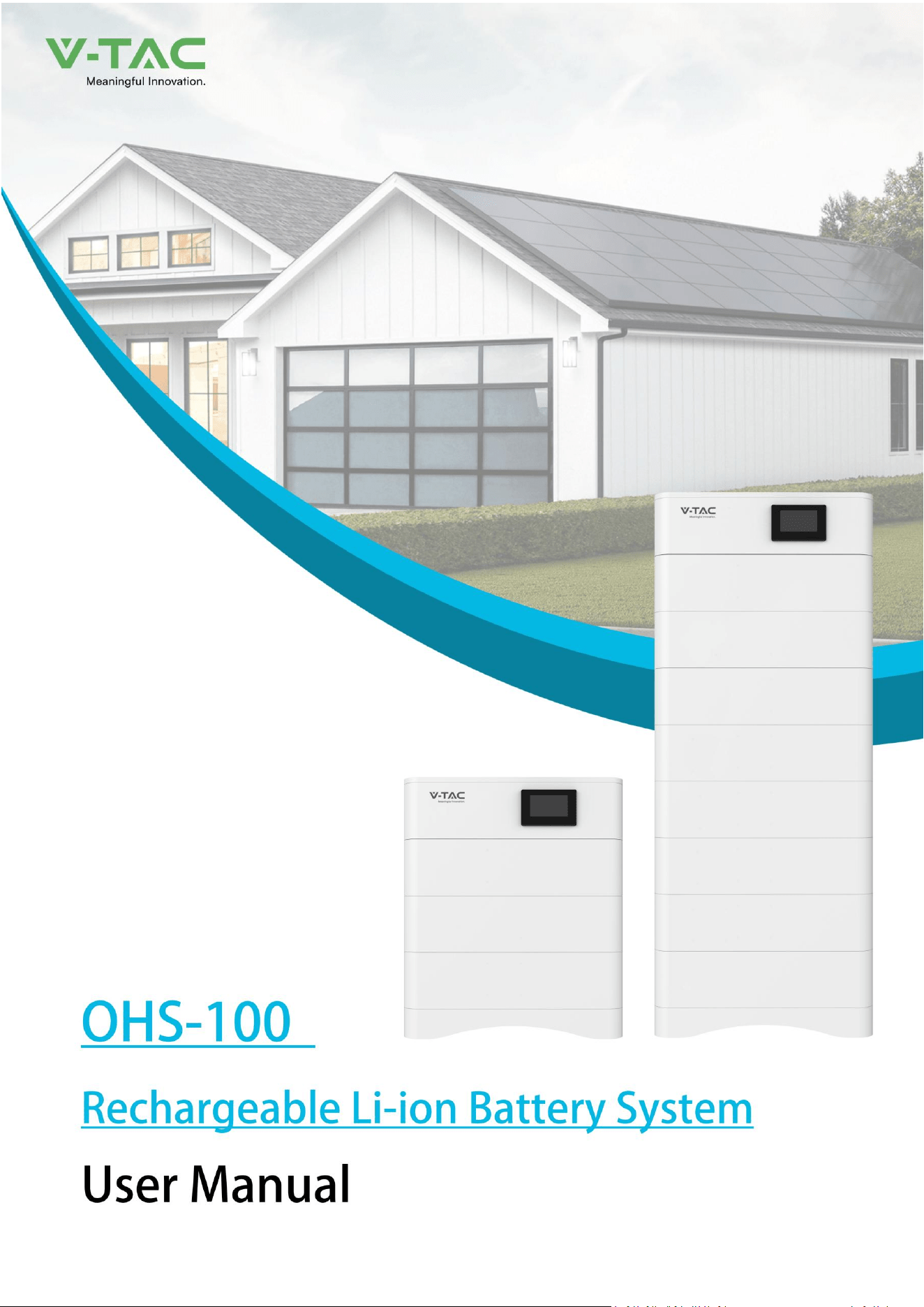
1.2 Brief Introduction
51.2V100AH lithium iron phosphate battery system is a standard battery system unit, customers can
choose a certain number of 51.2V100AH according to their needs, by connecting series to form a larger
capacity battery pack, to meet the user's long-term power supply needs. The product is especially
suitable for energy storage applications with high operating temperatures, limited installation space,
long power backup time and long service life.
1.3 Product Properties
51.2V100AH energy storage product’s positive electrode materials are lithium iron phosphate,
battery cells are managed effectively by BMS with better performance, the system’s features
as below:
The whole module is non-toxic, non-polluting and environmentally friendly;
Cathode material is made from LiFePO4 with safety performance and long cycle life
Battery management system with better performance, possesses protection
function like over-discharge, over-charge, over-current, abnormal temperature.
Self-management on charging and discharging, Single core balancing function.
Intelligent design configures integrated inspection module.
Flexible configuration, multiple battery modules can be in parallel for expanding capacity
and power.
Flexible configurations allow parallel of multi battery for longer standby time.
Self-ventilation with lower system noise.
Less battery self-discharge, then recharging period can be up to 10 months during the
storage.
No memory effect so that battery can be charged and discharged shallowly.
With wide range of temperature for working environment, -10℃ ~ +55℃, circulation
span and discharging performance are well under high temperature.
___________________________________________ USER MANUAL
4
2. Product Specification
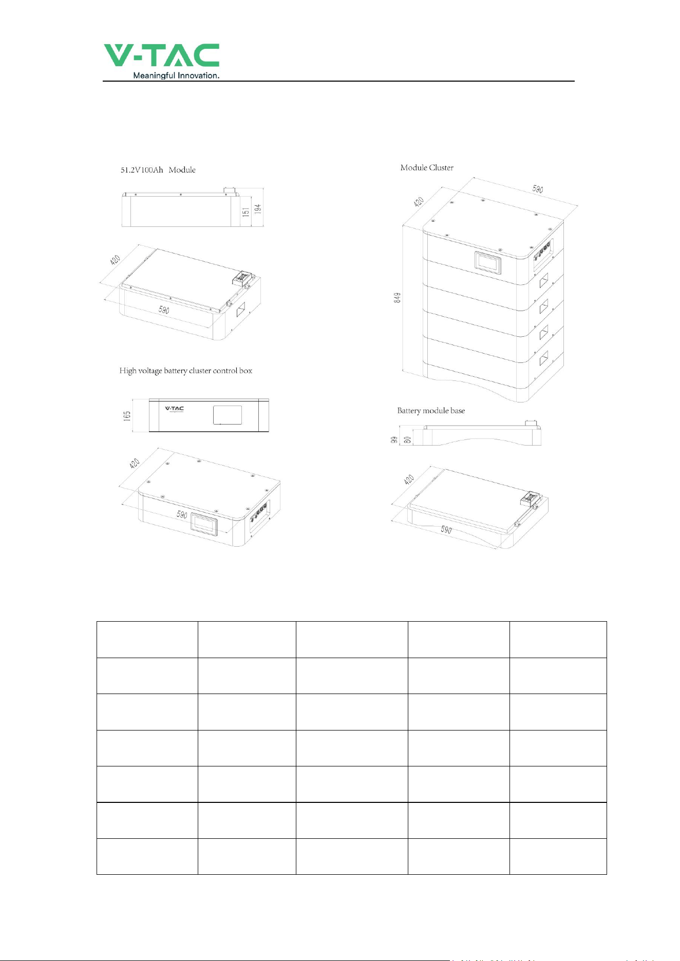
2.1 Size and Weight
Table 2-1 Device size
Product
Nominal Voltage
(
V
)
Nominal Capacity
(
Ah
)
Dimension
(
mm
)
Weight
(
Kg
)
OHS15K-100
153.6
100
590*420*698
161.4
OHS20K-100
204.8
100
590*420*849
207.0
OHS25K-100
256
100
590*420*1000
252.6
OHS30K-100
307.2
100
590*420*1151
298.2
OHS35K-100
358.4
100
590*420*1302
343.8
OHS40K-100
409.6
100
590*420*1453
389.4

___________________________________________ USER MANUAL
5
2.2 Performance Parameter
Table 2-2 performance parameter
Technical specification
15KWH
20KWH
25KWH
30KWH
35KWH
40KWH
Installation Mode
Stackable
Battery Type
LifePO4(LFP)
Module Energy(kWh)
5.12
Module Nominal Voltage(V)
51.2
Module Capacity(Ah)
100
System Model
OHS15K-100
OHS20K-100
OHS25K-100
OHS30K-100
OHS35K-100
OHS40K-100
Battery Module Qty
InSeries(Optional)
3
4
5
6
7
8
System Nominal Voltage(V)
153.6
204.8
256.0
307.2
358.4
409.6
System Nominal
Capacity(KWh)
15.36
20.48
25.60
30.72
35.84
40.96
Usable Capacity(KWh)
12.29
16.38
20.48
24.58
28.67
32.77
Dimension (mm)
590*420*698
590*420*849
590*420*1000
590*420*1151
590*420*1302
590*420*1453
Weight (Kg)
161.4
207.0
252.6
298.2
343.8
389.4
Recommend
Charge/Discharge Current (A)
40
Communicaiton
CAN
Ingress Protection
IP65
Altitude
≤2000m
Cycle Life
25±2°C,0.5C/0.5C,EOL70%≥6000
Monitoring Parameters
System voltage,Current,cell voltage,cell temperature,module temperature
SOC
Intelligent algorithm
Working Temperature
0℃~45℃ Charge -10℃ ~55℃ Disharge
Storage Temperature
0~35℃
___________________________________________ USER MANUAL
6
2.3 Equipment Interface Instruction
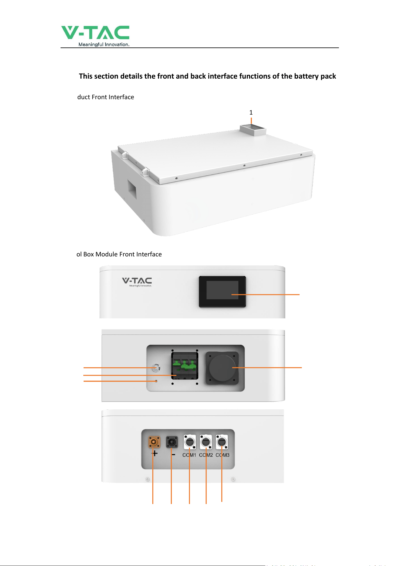
2.3.1 This section details the front and back interface functions of the battery pack
Product Front Interface
Control Box Module Front Interface
1
2
4
3
5
6
7 8 9 10 11
___________________________________________ USER MANUAL
7
Table 2-3 Interface Definition
Item
Name
Definition
1
Power Connector
For battery pack connect in series
2
Screen
Show battery information
3
Air Switch
Current Protection
4
BMS ON/OFF
Start BMS
5
Ground Point
Ground Point
6
WiFi
WiFi
7
Positive Output
DC + To Inverter
8
Negative Output
DC - To Inverter
9
Communication Port
Communication for debugging
10
Communication Port
Communication to inverter
11
Communication Port
Communication between battery cluster
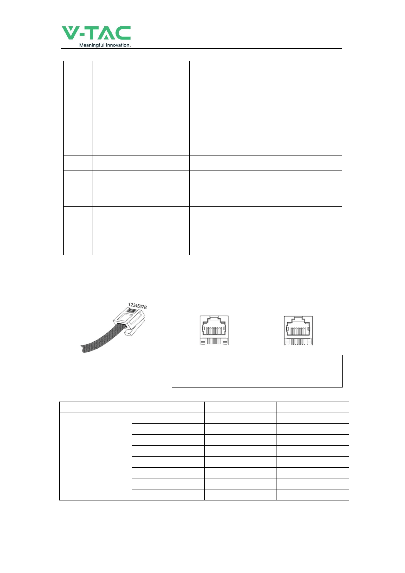
2.3.2 CAN/485/RS232 interface definition
RS485/CAN
RS485/CAN
Communication to
inverter
Communication between
battery cluster
PIN position
Color
Definition
RS485/CAN
PIN1
Orange/White
485B1
PIN2
Orange
485A1
PIN3
Green/White
GND
PIN4
Blue
CANH
PIN5
Blue/White
CANL
PIN6
Green
GND
PIN7
Brown/White
485A2
PIN8
Brown
485B2
___________________________________________ USER MANUAL
8
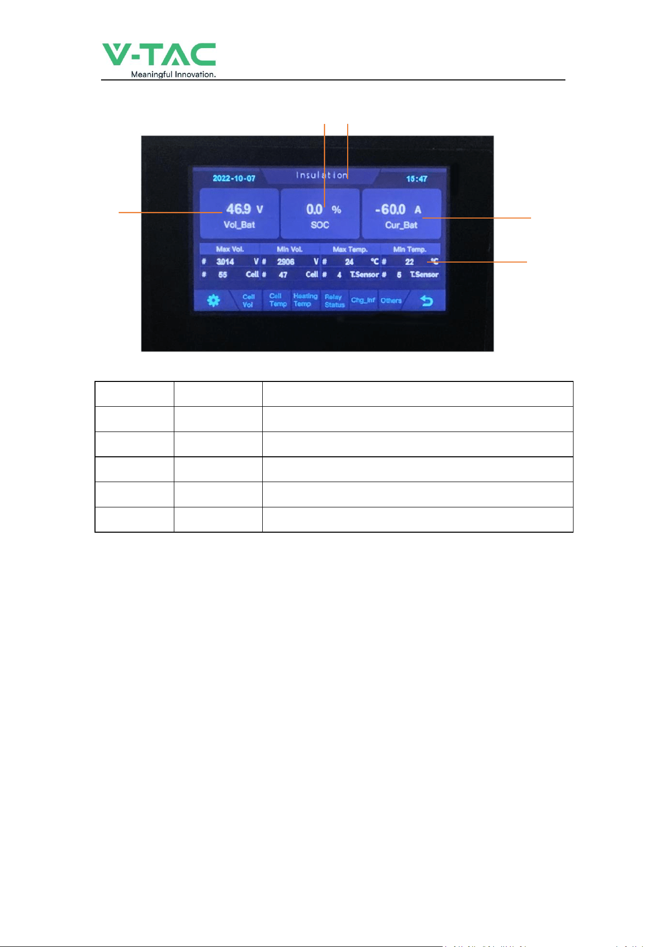
2.3.4 Display
2
NO.
Description
Function
1
SOC
Display real-time SOC value of energy storage system
2
Voltage
Display real-time voltage
3
Temperature
Display battery highest temperature
4
Current
Display battery real-time temperature
5
System status
READY means normal operation, ALM means system failure
2.4 Battery Management System(BMS)
2.4.1 BMS Protection and Alarm
Over Voltage Alarm/Protection in Charging:
When total voltage or any battery cell voltage reaches the rated
alarm value during charging stage, the alarm light will flash. When reaches the rated protection value,
the alarm light will on, battery will stop charge. After total voltage or all cell voltage back to rated
range, the protection is over
Low Voltage Protection in Discharging:
Battery system will stop supply power to the outside, when any battery cell voltage or total
voltage is lower than the rated protection value during discharging, the over-discharging
protection is activated. When the voltage of each cell back to rated return range, the protection is
over.
1 5
3
4

___________________________________________ USER MANUAL
9
Over Current Protection in Charging:
When the charge current
>
50A, BMS will stop output, after current lower than 50A, will start
automatically.
Over Current Protection in Discharging
:
When the discharge current is higher than 50A, BMS will stop output, after current lower than 50A,
will start automatically.
Low/Over temperature protection in charging
:
When battery’s temperature is beyond range of -0
℃
~+45
℃
during charging, temperature
protection is activated, device stops charging.
The protection is over when temperature back to rated working range.
Low/Over temperature protection in discharging
:
When battery’s temperature is beyond range of -10
℃
~+55
℃
during discharging, temperature
protection is activated, device stops supplying power to the outside.
The protection is over when temperature back to rated working range.
Short Circuit Protection
:
When the battery is activated from the shutdown state, if a short circuit occurs, the system starts
short-circuit protection for 60 seconds.
Self-Shutdown
:
When device connects no external loads and power supply and no external communication for
over 72 hours, device will dormant standby automatically.
___________________________________________ USER MANUAL
10
3. Installation and Configuration
3.1 Preparation for installation
3.1.1 Safety Requirement
This system can only be installed by personnel who have been trained in the power supply
system and have sufficient knowledge of the power system.
The safety regulations and local safety regulations listed below should always be followed during
the installation.
All circuits connected to this power system with an external voltage of less than 500V
must meet the SEHV requirements defined in the IEC60950 standard.
If operating within the power system cabinet, make sure the power system is not
charged. Battery devices should also be switched off.
Distribution cable wiring should be reasonable and has the protective measures to avoid
touching these cables while operating power equipment.
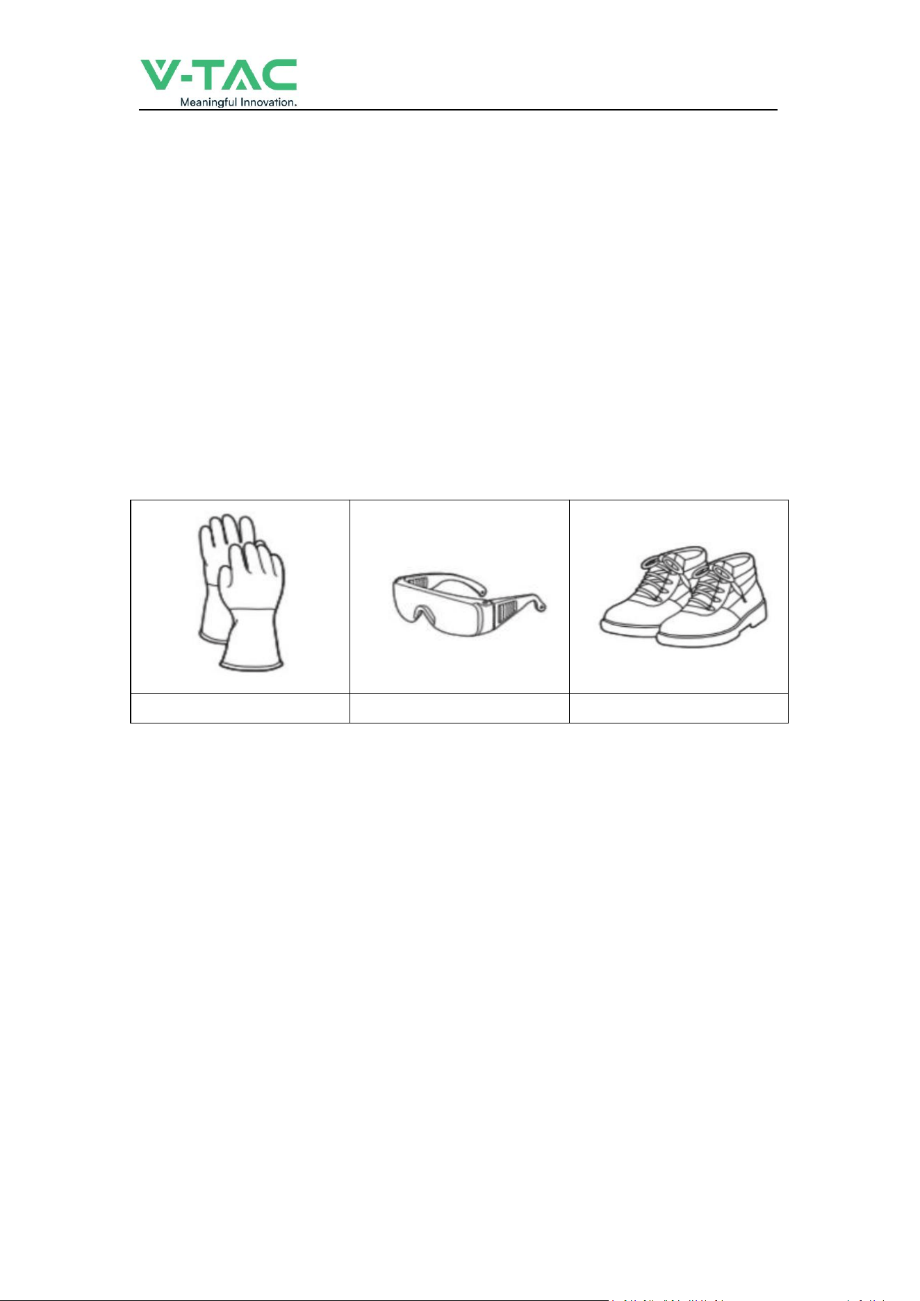
when installing the battery system, must wear the protective items below:
The isolation gloves
Safety goggles
Safety shoes
3.1.2 Environmental requirements
Working temperature: 0
℃
~ +45
℃
Charging temperature range is 0
℃
~+45
℃
,
Discharging temperature range is -10
℃
~+55
℃
Storage temperature: 0
℃
~ +35
℃
Relative humidity: 5% ~ 85%RH
Elevation: no more than 2000m
Operating environment: Indoor installation, sites avoid the sun and no wind, no conductive dust and
corrosive gas.
And the following conditions are met:
Installation location should be away from the sea to avoid brine and high humidity environment.
The ground for product arrangement shall be flat and level.
N
o flammable explosive materials near the installation site.
The optimal ambient temperature is 15
℃
~ 30
℃
Keep away from dust and messy zones

___________________________________________ USER MANUAL
11
3.1.3 Tools and data
Tools and meters that may be used are shown in table 3-1.
Table 3-1 Tool instrument
NAME
Screwdriver(Slotted、Phillips)
Multimeter
Torque wrench
Clamp current meter
Diagonal pliers
Insulation tape
Pointed nose pliers
Temperature meter
Pliers to hold the wire
Anti-static bracelet
Stripping pliers
Cable tie
Electric drill
Tape measure
3.1.4 Technical preparation
Electrical interface check
Devices that can be connected directly to the battery can be user equipment, power supplies, or other
power supplies.
Confirm whether the user's PV power generation equipment, power supply or other power supply
equipment has a DC output interface, and measure whether the DC power output voltage meets the
voltage range requirements in Table 2-2.
Confirm that the maximum discharge current capability of the DC power interface of the user's
photovoltaic power generation equipment, power supply or other power supply equipment should be
higher than the maximum charging current of the products used in
Table 2-2.
If the maximum discharge capacity of the DC power interface of the user's photovoltaic power
generation equipment is less than the maximum charging current of the products used in Table 2-2,
the DC power interface of the user's photovoltaic power generation equipment shall have a current
limiting function to ensure the normal operation of the user’s equipment.
Verify that the maximum operating current of the battery-powered user equipment (inverter DC
input) should be less than the maximum discharge current of the products used in Table 2-2.
The security check
Firefighting equipment should be provided near the product, such as portable dry powder fire
extinguisher.
Automatic fire fighting system shall be provided for the case where necessary.
No flammable, explosive and other dangerous materials are placed beside the battery.
3.1.5 Unpacking inspection
When the equipment arrives at the installation site, loading and unloading should be carried out
according to the rules and regulations, to prevent from being exposed to sun and rain.
Before unpacking, the total number of packages shall be indicated according to the shipping list
attached to each package, and the case shall be checked for good condition.
In the process of unpacking, handle with care and protect the surface coating of the object.
Open the package, the installation personnel should read the technical documents, verify the list,
according to the configuration table and packing list, ensure objects are complete and intact, if the
internal packing is damaged, should be examined and recorded in detail.
___________________________________________ USER MANUAL
12
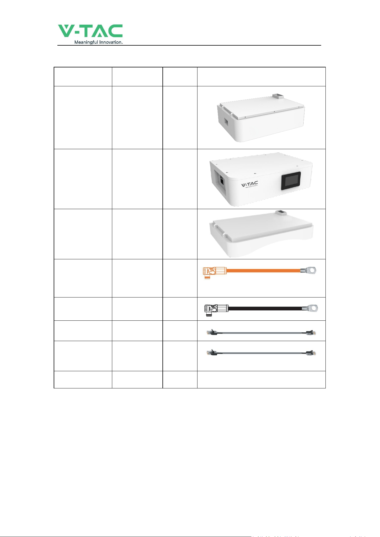
Packing list is as follows:
Item
Specification
Quantity
Figure
Battery module
51.2V/100AH
5.12Kwh
N
High voltage
battery cluster
control box
50A
1
Battery module
base
1
Positive Cable to
inverter
Red/6~4 AWG
/L2000mm
1
Negative Cable to
inverter
Black/6~4 AWG
/L2000mm
1
Communication
Cable to inverter
L2000mm
1
Communication
Cable between
batteries
L1000mm
1
User Manual
1
___________________________________________ USER MANUAL
13
3.2 Equipment installation
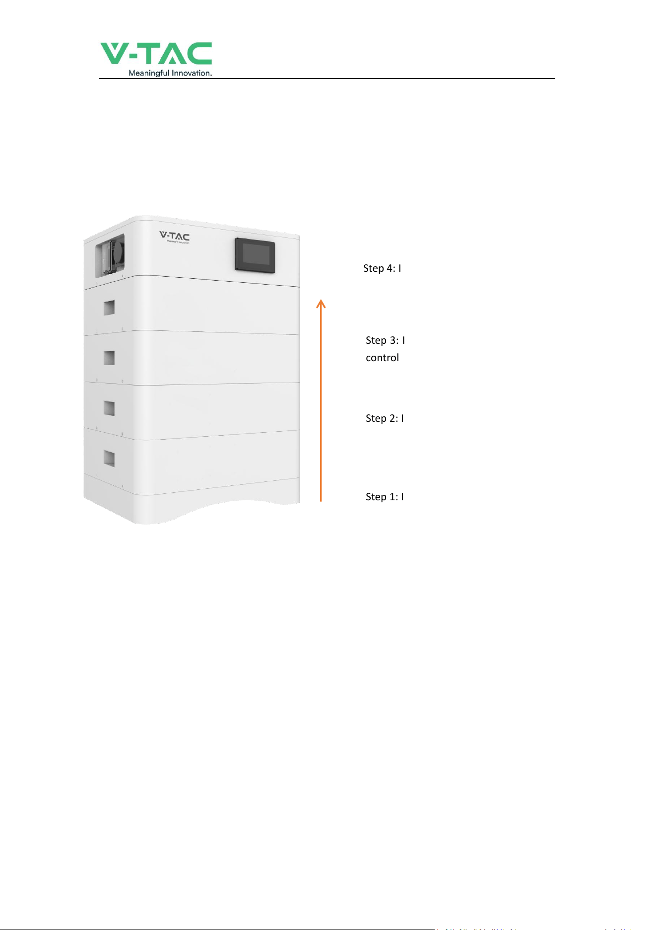
3.2.1 Installation Steps
Step 1 Mechanical Installation
(1) Installation step:
Step 1: Install the Battery module base
Step 2: Install the Battery module
Step 3: Install the High voltage battery cluster
control box
Step 4: Install side fastening screws
___________________________________________ USER MANUAL
14
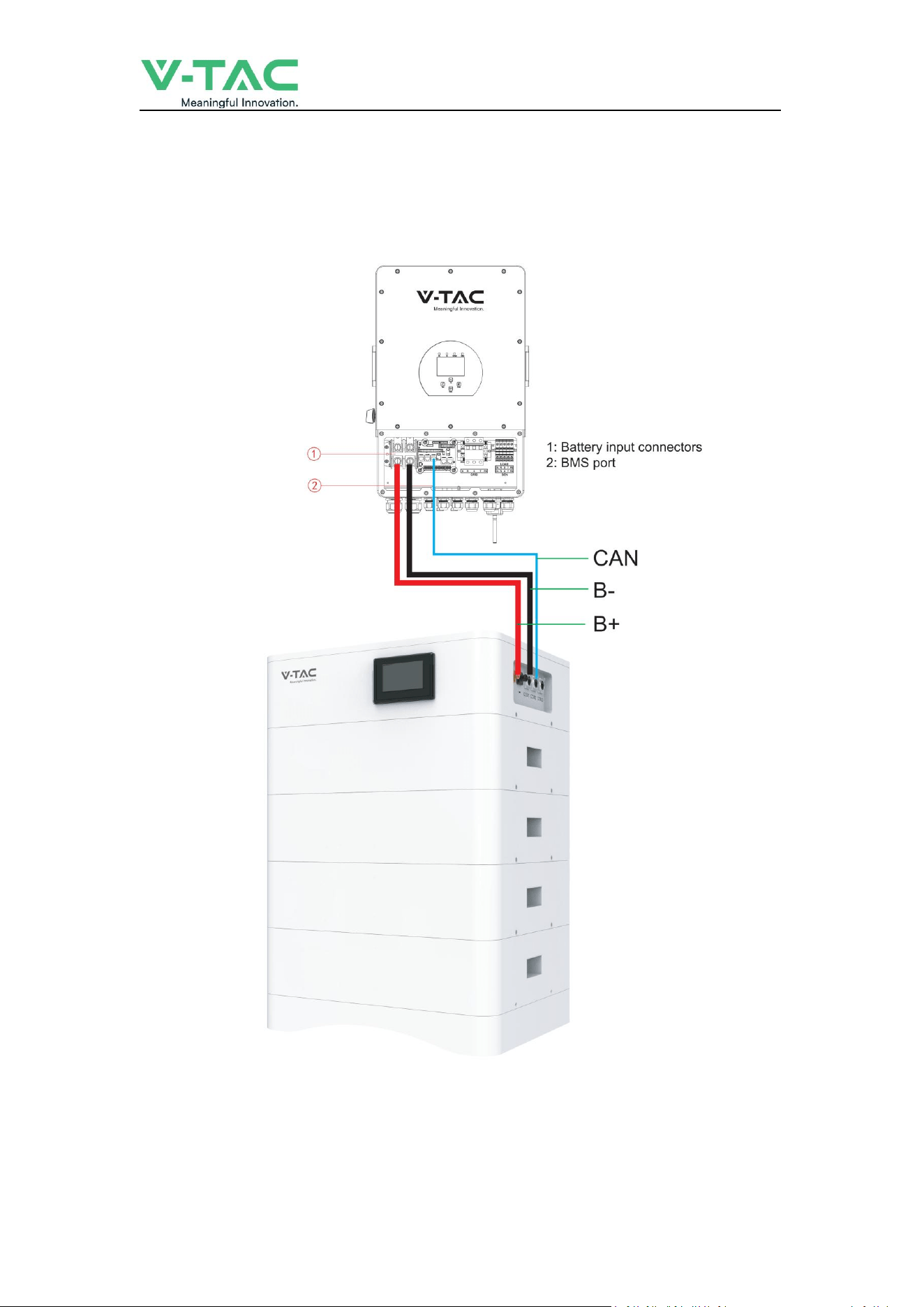
Step 2 Electrical installation
(1) Connect with inverter
___________________________________________ USER MANUAL
15
3.2.2 Battery parameter settings on the inverter
If your inverter do not have communication function with OHS-100 battery pack, please set
inverter follow next data.
Max Charging(module) Voltage: 56.0V*N
Shut Down(cut off) Voltage: 49.0V*N
(
SOC20%
)
Shut Down(cut off) SOC: 20%
Restart Voltage: 51.2V*N
Max Charge Current: 50A
Max Discharge Current: 50A
4. Installation and Configuration
4.1 Battery system usage and operation instructions
After completing the electrical installation, follow these steps to start the battery system.
1. Open the BMS on/off, wait the screen open and show battery with normal status.
2. After the LCD screen show battery with normal status, open the air switch.
1. After pressing the power button, if the LCD screen show battery with ALM status,
please refer to the "4.2 Alarm description and processing ". If the
failure cannot be eliminated, please contact the dealer timely.
2. Use a voltmeter to measure whether the voltage of the circuit breaker battery access
terminal is higher than48V*N, and check whether the voltage polarity is consistent with
the inverter input polarity. If the circuit breaker battery input terminal has a voltage
output and is greater than 48V*N, then the battery begun to work normally.
3. After confirming that the battery output voltage and polarity are correct, turn on the
inverter, close the circuit breaker.
4. Check if the indicator of the inverter and battery connection (communication indicator
and battery access status indicator) is normal. If it is normal, successfully complete the
connection between the battery and the inverter. If the indicator light is abnormal,
please refer to the inverter manual for the cause

___________________________________________ USER MANUAL
16
4.2 Alarm description and processing
When protection mode is activated or system failure occurred, the alarm signal will be given
through the working status indicator on the front panel of the BSM48100HP. The network
management can query the specific alarm categories.
If the fault such as single cell over voltage, charging over-current, under-voltage protection,
high-temp protection and other abnormalities which affects the output, please deal with it
according to Table 4-1.
Table 4-1 Main alarm and Protection
Statue
Alarm category
Alarm indication
Processing
Charge state
Over-current
RED
Stop charging and find
out the cause of the
trouble
High temp
Red
Stop charging
Discharge state
Over-current
Red
Stop discharging and
find out the cause of
the trouble
High temp
Red
Stop discharging and
find out the cause of
the trouble
Total voltage
undervoltage
Red
Start charging
Cell voltage
undervoltage
Red
Start charging
4.3 Analysis and treatment of common faults
Analysis and treatment of common faults in the Table 4-2:
Table 4-2 Analysis and treatment of common faults
No
.
Fault phenomenon
Reason analysis
Solution
1
The indicator does not respond
after the power on Total
voltage lower than 40V*N
Check the total voltage
Total voltage lower than 40V*N
Check the total voltage
2
No DC output
Battery data status is abnormal.
Battery gets into over-discharged
protection
Read the battery
information on the
monitor.
3
The DC power supply
time is too short
Battery capacity become smaller
Storage battery
replacement or add
more modules
4
The battery can't be
fully charged to 100%
Charging voltage is too low
Adjust charging voltage
at 57V*N

___________________________________________ USER MANUAL
17
5
The power cable
sparks once power on
and ALM light RED
Power connection short-circuit
Turn off the battery,
check the cause of the
short circuit
6
Communication fault
The DIP setting of the host is
wrong/ the battery type of the
inverter is wrong/
Communication cable used
incorrectly/The communication
cable is incorrectly connected at
the battery communication port
or the inverter communication
port/The battery firmware
version is too low to support the
inverter
Check these possible
causes one by one
If you need any technical help or have any question, please contact the dealer in time.