Loading ...
Loading ...
Loading ...

4
OPERATION
WARNING
To reduce the risk of injury, always
wear proper eye protection marked
to comply with ANSI Z87.1.
WARNING
Maintain proper footing and bal-
ance when performing pulling
operations. Do not pull from a ladder. If a snag or
resistance is encountered, a ladder could become
unstable which may result in a loss of balance or
control.
Using the Control Switch
The control switch may be set to three positions:
feed, retract and lock. Due to a lockout mechanism,
the control switch can only be adjusted when the
trigger is not pulled. Always allow the motor to come
to a complete stop before using the control switch.
1. To feed the sh tape, push the control switch in
the direction shown.
Push for
Retract
Push for
Feed
PUSH TO CENTER TO LOCK
2. To retract the sh tape, push the control switch in
the direction shown.
3. To lock the trigger, push the control switch to the
center position. The trigger will not work when the
control switch is in the locked position.
Always remove the battery pack before performing
maintenance, changing accessories, storing the
tool and any time the tool is not in use.
General Operation
1. Install the battery pack.
2. Support sh tape during use.
3. To feed the conduit run, move the control switch
to the feed position and pull the trigger.
4. To vary the speed, increase or decrease pressure
on the trigger. The further the trigger is pulled, the
greater the speed.
5. While extending, monitor the sh tape. When
nearing full extension, the sh tape will be marked
with yellow paint. Once yellow paint is visible, stop
extending. Further extension could damage or
break the sh tape.
6. Once the sh tape has been extended out to the
pulling point, release the trigger.
7. Move the control switch to the lock position or
remove the battery pack.
8. Fasten your wire or pull line to the sh tape se-
curely. Wrapping the connection with plastic tape
may help prevent it from unraveling during pulling.
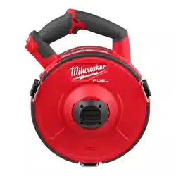
FUNCTIONAL DESCRIPTION
1
1
1
7
2
3
4
5
6
8
1. Latches
2. Nozzle notch
3. Trigger
4. Control switch
5. Handle
6. Nozzle
7. Hub
8. Cartridge grips
9. Cartridge
9
ASSEMBLY
WARNING
Recharge only with the charger
specied for the battery. For spe-
cic charging instructions, read the operator’s
manual supplied with your charger and battery.
Removing/Inserting the Battery
To remove the battery, push in the release buttons
and pull the battery pack away from the tool.
WARNING
Always remove battery pack before
changing or removing accessories.
To insert the battery, slide the pack into the body
of the tool. Make sure it latches securely into place.
WARNING
Only use accessories specically
recommended for this tool. Others
may be hazardous.
Installing a Cartridge
1. Align the nozzle of the cartridge to the nozzle notch
of the tool and place the cartridge around the tool
hub until fully seated.
2. Secure the cartridge to the tool with the three
latches.
3. To remove, unlatch and use cartridge removal grips
to separate the cartridge from the tool.
Loading ...
Loading ...
Loading ...