

About this document
This manual is intended for administrators and users of the AXIS
P1214-E Network Camera, a nd is applicable to firmware 5.40 and later.
It includes instructions for using and managing the product on your
network. Previous experience of networking will be of use when using
this product. Some knowledge of UNIX or Linux-based systems may also
be beneficial, for developing shell scripts and applications. Later version
of this document will be posted to the Axis website, as required. See
also the product’s online help, available v ia the web-based interface.
Liability
Every c are has been taken in the preparation of this manual. Please
inform your local Axis office of any inaccuracies o r omissions. Axis
Communications AB cannot be held responsible for any technical or
typographical errors and reserves the right to make changes to the
product and manuals without prior notice. Axis Communications AB
makes no warranty of any kind with regard to the material contained
within this document, including, but not limited to, the implied
warranties of merchantability and fitness for a particular p urpose. Axis
Communications AB shall not be liable n or responsible for incidental or
consequential damages in connection with the furnishing, performance
or use of this material. This produ ct is only to be used for its intended
purpose.
Intellectual Property Rights
Axis AB has intellectual property rights relating to technology embodied
in the product described in this document. In particular, and without
limitation, these intellectual property rights may include one or more
of the patents listed at http://www.axis.com/patent.htm and one or
more additional patents or pending patent applications in the US and
other countries.
This produc t contains licensed third-party software. See t he menu item
“About” in the product’s user interface for more information.
This product contains source code copyright Apple Computer,
Inc.,underthetermsofApplePublicSourceLicense2.0(see
http://www.opensource.ap ple.com/apsl). The source code is available
from h ttp://developer.apple.com/darwin/projects/ bon jour/
Equipment Modifications
This equipment must be installed and used in strict accordance with the
instructions given in the user documentation. This equipment contains
no user-serviceable components. Unaut horized equ ipment changes or
modifications will invalidate all applicable regulatory certifications
and approvals.
Trademark Acknowledgments
Apple, Boa, Bonjour, Ethernet, Internet Explorer, Linux , Microsoft,
Mozilla, Real, SMPTE , QuickTime, UNIX, Windows , Windows Vista and
WWW are registere d trademarks of the respective holders. Java and
all Java-based trademarks and logos are trademarks or registered
trademarks of Oracle and/or its affiliates. UPnP
TM
is a certific
ation
mark of the UPnP
TM
Implementers Corporation.
Electromagnetic Compatibility (EMC)
This equipment has been designed and tested t
ofulfill applicable
standards for:
• Radio frequency emission when installe d according to the
instructions and used in it s intended environment.
• Immunity to electrical and electromagnetic phenomena whe n
installed according to the inst ructions and used in its intended
environment.
USA
This equipment has been tested using a shielded network cable (STP)
and found to comply with the limits for a Class B digital device,
pursuant to part 15 of the FCC Rules . These limits are designed
to provide reasonable protection against harmful interference in a
residential installation. This equipment generates, uses and can radiate
radio frequency energy and, if not installe d and used in accordance
with the instructions, may cause harmful interference to radio
communications. However, there is no g uarantee that interference
will not occur in a particular installation. If this equipment does
cause harmful interference to radio or television reception, which
can b e determined by turning the equipment off and on, the user is
encouraged to try to correct the interference by one or more of the
following measures:
• Reorient or relocate the receiving antenna.
• Increase the separation between the equipment and receiver.
• Connect the equipment into an outlet on a circuit different from
that to which the receiver is connected.
• Consult the dealer or an experienced radio/TV technician for help.
Canada
This C la ss B digital apparatus comp lies with Canad ian ICES-0 03.
Europe
This digital equipment fulfills the requirem ents for RF emission
according to the Class B limit of EN 550 2 2.
This product fulfills the requirements for immunity according
to EN 61000-6-1 residential, commercial and light-industrial
environments.
This product fulfills the requirements for immunity according to
EN 55024 office a n d commercial environments.
Australia/New Zealand
This digital equipme nt fulfills the requiremen ts for RF emission
according to the Class B limit of AS/NZS CISPR 22.
Korea
이 기기는 가정용(B급) 전자파적합기기로서 주로 가정에서 사
용하는 것을 목적으로 하며, 모든 지역에서 사용할 수 있습니다.
Japan
この装置は、クラスB 情報技術装置です。この装置は、家庭
環境で使用することを目 的としていますが、この装置がラジ
オやテレビジョン受信機に近接して使用されると、 受信障
害を引き起こすことがあります。 取扱説明書に従って正し
い取り扱いをして下さい。
Safety
This product complies with IEC/EN 60950-1 and IEC/EN 60950-22,
Safety of Information Technology Equipment.
The power supply used with this product shall f ulfill the requirements
for Safety Extra Low Voltage (SELV) and Limited Power Source (LPS)
according to IEC/EN/UL 60950-1.
Support
Should you require any technical assistance, please contact your Axis
reseller. If your questions cannot be answered immediately, your
reseller will forward your queries through the appropriate channels to
ensure a rapid re sponse. If you are connected to the Internet, you can:
• download u ser documentation and software updates
• find answers to res
olved problems in the FAQ database. Search
by product, category, or phrase
• report problems to Axis support staff by logging in to your private
support area
• chat w ith Axis support staff (selected countries only)
• visit Axis Support at www.axis.com/techsup/
Learn More!
Visit Axis learning c enter www.axis.com/academy for useful trainings,
webinars, tutorials and guides.

AXIS P1214–E Network Camera
Table of Contents
HardwareOverview .......................................... 4
Connectors .................................................... 4
LEDIndicators .................................................. 5
ShortenSensorUnitCable ........................................ 5
AccessingtheProduct ....................................... 7
Accessfromabrowser ........................................... 7
AccessfromtheInternet .......................................... 8
SettheRootPassword ........................................... 8
TheLiveViewPage .............................................. 9
MediaStreams ............................................. 11
HowtoStreamH.264 ............................................ 11
MJPEG ........................................................ 11
AXISMediaControl(AMC) ........................................ 11
AlternativeMethodsofAccessingtheVideoStream .................... 12
SettingUptheProduct ...................................... 14
BasicSetup .................................................... 14
Video ..................................................... 15
VideoStream ................................................... 15
Stream Profiles ................................................. 16
CameraSettings ................................................ 17
Overlay ........................................................ 17
PrivacyMask ................................................... 18
Live View Config ............................................ 19
Detectors .................................................. 22
CameraTampering .............................................. 22
MotionDetection ............................................... 22
Applications . .............................................. 24
Events .................................................... 25
SettingUpanActionRule ........................................ 26
Recipients ..................................................... 26
Schedules ...................................................... 27
Recurrences .................................................... 27
Recordings ................................................. 28
RecordingList .................................................. 28
Continuousrecording ............................................ 28
SystemOptions ............................................. 30
Security ....................................................... 30
Date&Time .................................................... 31
Network ....................................................... 32
Storage ....................................................... 37
Ports&Devices ................................................. 38
Maintenance ................................................... 38
Support ....................................................... 39
Advanced ...................................................... 39
ResettoFactoryDefaultSettings ................................... 40
Troubleshooting ............................................ 41
CheckingtheFirmware ........................................... 41
UpgradingtheFirmware .......................................... 41
EmergencyRecoveryProcedure .................................... 41
Symptoms,PossibleCausesandRemedialActions ..................... 42
Technical Specifications ...................................... 46
PerformanceConsiderations ....................................... 48
3
AXIS P1214–E Network Camera
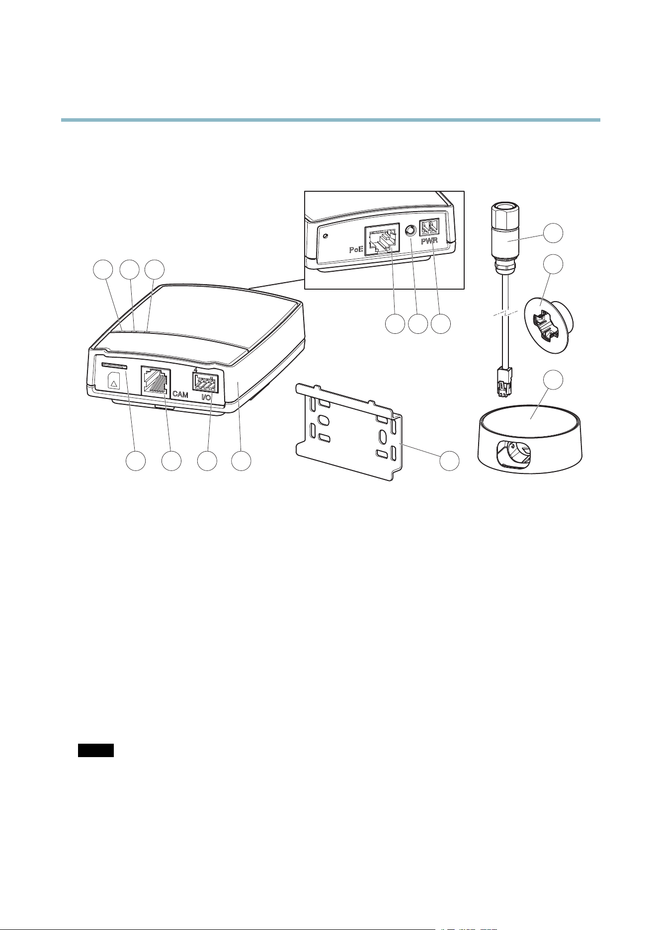
Hardware Overview
Hardware Overview
10
11
98
7
321
654
12
13
14
1
Power indica tor LED
2
Status indicator LED
3
Network indicator LED
4
SD card slot (microSD card)
5
Camera connector
6
I/O terminal connector
7
Main unit
8
Network connector
9
Control button
10
Power connector
11
Mounting rail
12
Sensor unit
13
Mounting bracket
14
Outdoor housing
Connectors
For technical s peci
fications, see page 46.
Network connec
tor - RJ-45 Ethernet connector. Supports Power over Ethernet (PoE).
NOTICE
The prod
uct shall be connected using a shielded network cable (STP). All cables connecting the product to the network switch
shall be shielded (STP) and intended for their specific use. Make sure that the network switch is properly grounded . See
Electromagnetic C ompatibility (EMC) for regulatory requirements.
SD card slot - A standard or high-capacity microSD card (not included) can be used for local recording with removable storage.
4

AXIS P1214–E Network Camera
Hardware Overview
NOTICE
To prevent corruption of recordings, the S D card should be unmounted before removal. To unmount, go to Setup > System
Options > Storage > SD Card an d click Unmount.
Control button - The control button is used for:
• ConnectingtoanAXISVideoHostingSystemservice.Seepage 33. To connect, p ress and hold the button for about
1 second until the Status LED flashes green.
• ConnectingtoAXISInternetDynamicDNSService. Seepage 33. To connect, press and hold the button for
about 3 seconds.
• Resetting the product to factory default settings. See page 40.
Power connector - 2-pin terminal block for power input.
I/O terminal connector - Use in applications for e.g. motion detection, event triggering, time lapse recording and alarm notifications.
In addition to an auxili ary power and a GND pin, the I/O terminal connector provides the interface to:
• Digital output – For connecting external devices such as relays and LEDs. Connected devices can be activated by
the VAPIX® Application Programming Interface, output b u ttons on the Live View page or by an Actio n Rule. The
output will show as active (shown under System Options > Ports & Devices) if the alarm device is activated.
• Digital input – An alarm input for connecting devices that can toggle between an open and closed circuit, for
example: PIRs, door/window contacts, glass break detectors, etc. When a signal is received the state changes and
the input becomes a ctive (shown under System Options > Ports & Devices).
LED Indicators
LED
Color
Indication
Green
Steady for connection to a 100 MBit/s network. Flashes for network activity.
Amber
Steady for connection to a 10 MBit/s network. Flashes for network activity.
Network
Unlit No network connection.
Green Steady g reen for normal operation.
Amber
Steady during startup and when restoring settings.
Red
Slow flash for failed upgrade.
Status
Unlit No connection between sensor unit a nd main unit.
Green
Normal operation.
Power
Amber
Flashes g
reen/amber during firmware upgrade.
Note
• The Status LED can be configured to be unlit d uring normal operation. To configure, go to Setup > System Options >
Ports & Devices > LED. See the online help for more information.
•T
he Status LED can be configured to flash while an event is active.
• The Status LED can be configured to flash for identifying the unit. Go to Setup > System Options > Maintenance .
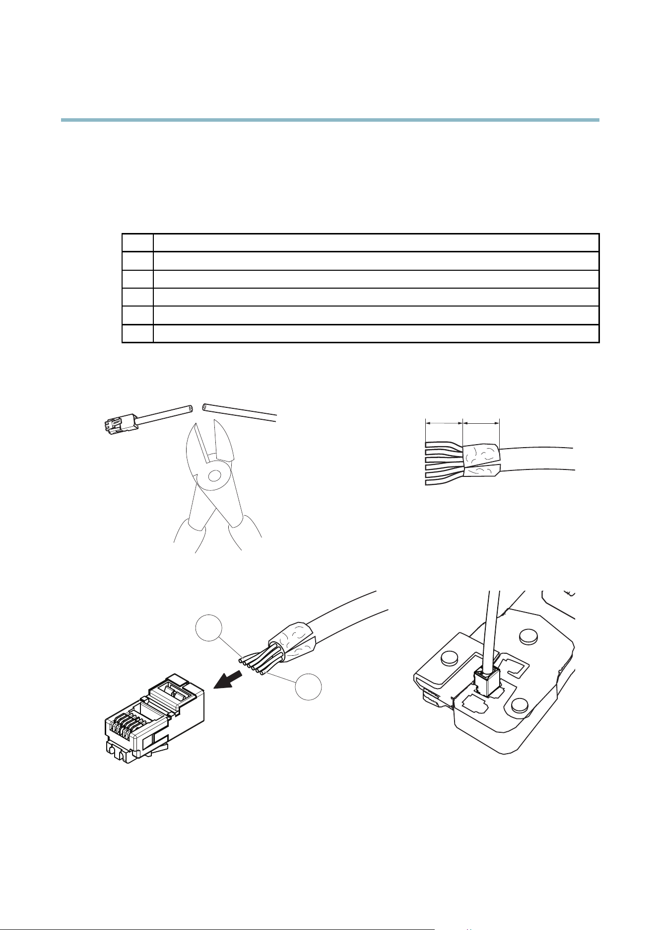
Shorten Sensor Unit Cable
The sensor unit is delivered with a 8 m (26 ft) cable.
To shorten the cable follow these steps:
5
AXIS P1214–E Network Camera
Hardware Overview
1. Cut the cable to the desired length. Measure from the sensor unit.
2. Strip the plastic outer coating from the end of the cable.
3. Peel back the shield.
4. Flatten the colored wire s in the order described below.
1
Brown
2
White/brown
3
Not used
4
Not used
5
White/blue
6
Blue
5. Insert the wires all the way into a shielded 6P6C RJ12 co nnector. Make sure that the wires stay in the correct order.
6. Use a crimping tool to fasten the connector to the cable.
14 mm 14 mm
6
1
6
AXIS P1214–E Network Camera
Accessing the Product
Accessing the Product
To install the Axis product, refer to the Installation Guide supplie d with the product.
The product can be used with most operating systems and browsers. The recommended browsers are Internet Explorer with Windows,
Safari with Macintosh and Firefox with other operating systems. See Technical Specifications on page 46.Toviewstreamingvideoin
Internet Exp lore r, allow installation of AXIS Media Control (AM C) when prompted.
The Axis product includes one (1) H.264 decoder license for viewing video streams. The license is automatically installed with AMC.
The administrator can disable the install ation of the decoders, to prevent installation of unlicensed copies.
Note
• QuickTime
TM
is also supported for viewing H.264 streams.
• If your com puter restricts the use of additional software components, the product can be configured to use a Java
applet for viewing Motion JPEG.
Access from a browser
1. Start a browser (Internet Explorer, Firefox, Safari).
2. Enter the IP address or host name of the Axis product in the browser’s Location/Address field. To access the product from a
Macintosh computer (Mac OS X), click on the Bonjour tab and select the product from the drop-down list.
If you do not know the IP address, use AXIS IP Utility to locate the product on the network. For more information on how to
discover and assign an IP address, refer to the Installation Guide.
3. Enter your user name and p assword. If this is the first time the p roduct is accessed, the root password must first be
configured; for instructions see Set the Root Password on page 8 .
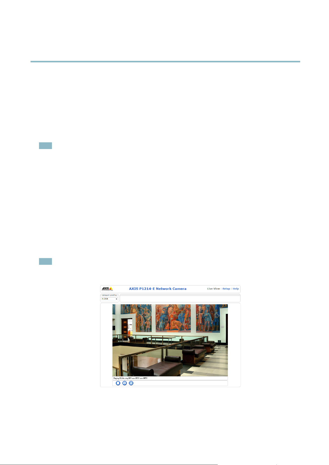
4. The product’s Live View page appears in your browser.
Note
The layout of the Live View page may have been customized to meet specific requirem ents. Consequently, some of the
examples and functions featured here may differ from those displayed i
n your own Live View page.
7
AXIS P1214–E Network Camera
Accessing the Product
Access from the Internet
Once connected, the Axis product is accessible on your local network (LAN). To access the product from the Internet you must
configure your network router to allow incoming data traffic to the product. To do this, enable the NAT-trave rs al feature, which
will attempt to automat ically configure the router to allow access to the product. This is enabled from Setup > System Options >
Network > TCP/IP Advan c ed.
For more information, please see NAT traversal (port mapping) for IPv4 on page 35. See also AXIS Internet Dynamic DNS Service at
www.axiscam.net For Technical notes on this and other topics, visit the Axis Support web at www.axis.com/techsup
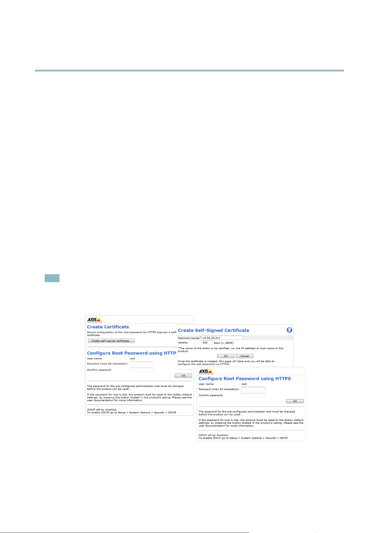
Set the Root Password
To gain access to the Axis product, you must set the password for the default administrator user root. This is done in the Configure
Root Password dialog , which appears when the product is accessed for the first time.
To prevent network eavesdropping, the root password can be set via an encrypted HTTPS connection, which requires an HTTPS
certificate. HTTPS (Hypertext Transfer Protocol over SSL) is a protocol used to encrypt traffic between web browsers and servers. The
HTTPS certificate ensures encrypted exchange of information.
To set the password via a standard HTTP connection, enter it directly in the first dialog.
To set the password via an encrypted HTTPS connection, follow these steps:
1. Click Create self-signed certificate.
2. Provide the requested information and click OK.Thecertificate is created and the password can now be set securely. All
traffic to and from the product is encrypted from this point on.
3. Enter a password and then re-enter to confirm the spelling. Click OK. The password has now been con figured.
Note
• The default administrator user name root is permanent and cannot be deleted.
• If the password for root is lost, the product must be reset to the factory default settings. See Reset to Factory Default
Settings on page 40.
Set Power Line F requency
Power line frequency is set the first time the Axis product is accessed and can only be changed from Plain Config(seepage 40)
or by resetting the product to factory default.
8
AXIS P1214–E Network Camera
Accessing the Product
Select the power line f req uency (50 Hz or 60 Hz) used at the location of the Axis product. Selecting the wrong frequency may cause
image flickeriftheproductisusedinfluorescent light environments.
When using 50 Hz, the maximum frame rate is limited to 25 fps.
Note
Power line frequency is different in different geographic regions. In the Americas, 60 Hz is usually used; most other parts of
the world use 50 Hz. Local v ariations may apply, always check with the local authorities.
The Live View Page
The controls and layout of the Live View page may have been customized to meet specific i nstallation requirements and user
preferences. Consequently, some of the examples and functions featured here may differ from those displayed in your own Live View
page. T he following provides an overview of each available control.
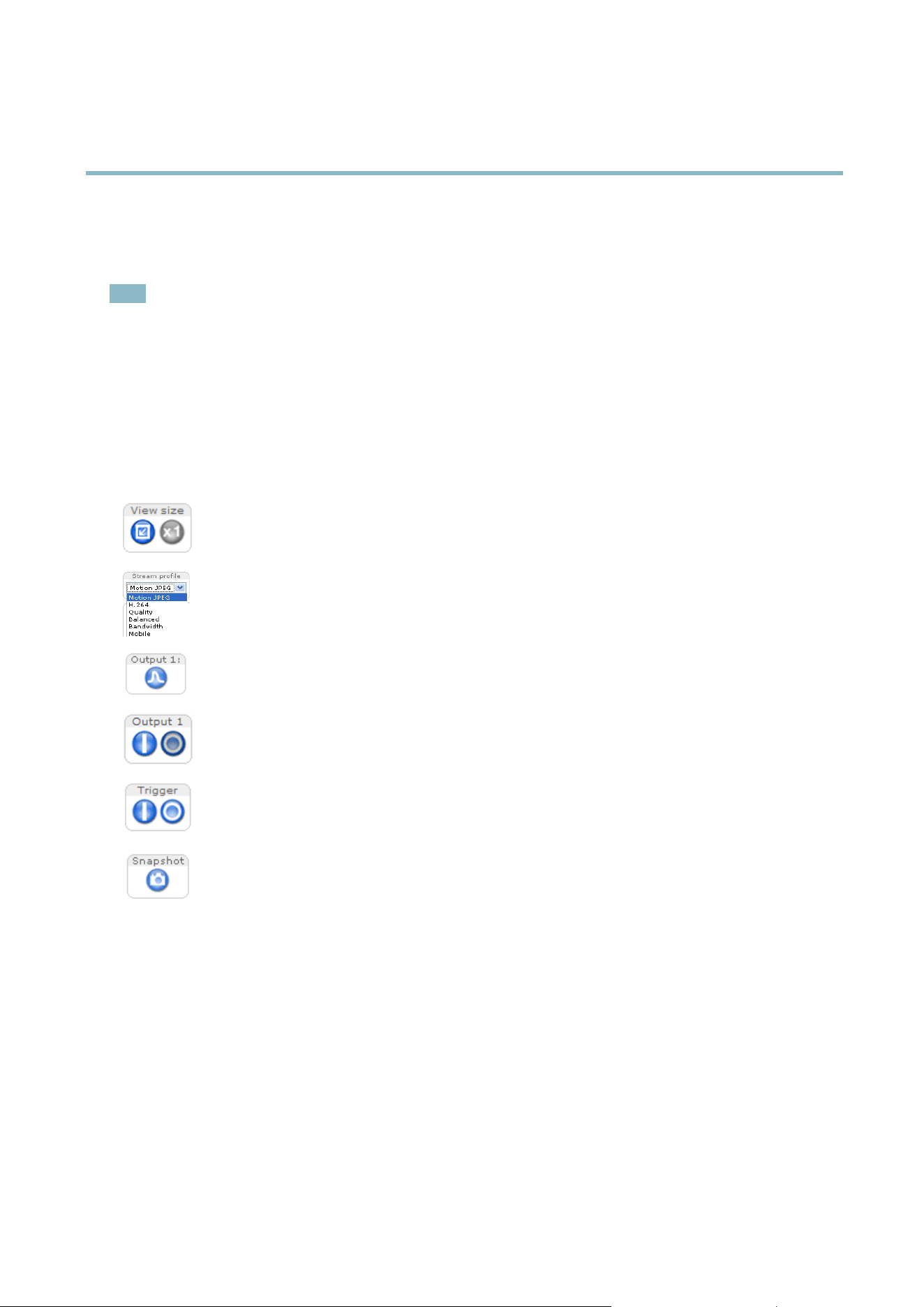
Controls on the Live View Page
Click View size to scale the image down to 800 pixels wide or to full scale. Only available in MJPEG.
The Stream Profile drop-down list allows you to select a customized or pre-programmed stream profile. Stream
profiles are configured under Video > Stream Profiles.SeeStream Profiles on page 16.
Click Pulse to activate the output for a defined period of time, such as switching on an external light for 20 seconds.
Click the Active/Inactive buttons to manually start and stop a connected device — e.g. s witch an external light
on and off.
The Manual Trigger button is used to trigger an action rule from the Live View page; see
page 9 . Enable this
button from Live View Config > Action Buttons.
Click Snapshot to save a snapshot of the video image. Right-click the video image to save it in JPEG format on your
computer. This button is primarily intended for use when the AXIS Media Control viewer toolbar is not available.
Enable this button from Live View Config > Action B
uttons.
Manual Trigger
The Manual Trigger is used to trig
ger an actio n rule f rom the L ive View page. The manual trigger can for exam ple be used to
validate actions during product installation and configuration.
To configure the m anual trigger:
1. Go to Setup > Events.
2. Click Add to add a new action rule.
3. From the Trigger drop-down list, select Input Signal.
4. From the second drop-down list, select Manual Trigger.
5. Select the desired action an d configure the other settings as required.
9

AXIS P1214–E Network Camera
Accessing the Product
For more information about action rules, see Events on pa ge 25.
To show the manual trigger buttons in the Live View page:
1. Go to Setup > Live View Layout.
2. Under Action Buttons,selectShow manual trigger button.
AXIS Media Control viewer toolbar
The AXIS M edia Control viewer toolbar is a vailable in Internet Explorer only. See AXIS Media Control (AMC) on page 11 for more
information. The toolbar displays the following buttons:
The Play button connects to the Axis product and starts playing a media stream.
The Stop button stops the media stream.
The Snapshot button takes a snapshot of the video image. The location where the image is saved can be specified
in the AMC Control Panel.
Click the View Full Screen button and the video ima ge will fill the entire screen. Press ESC (Escape) on the computer
keyboard to cancel full screen view.
The Record buttonisusedtorecordthecurrentvideostream.Thelocation where the recording is saved can be specified in
the AMC Control Panel. Enable this button from Live View Config > Viewer Settings.
10

AXIS P1214–E Network Camera
Media Strea ms
Media Streams
The Axis product provides severa l video stream forma ts. Your requirements and the properties of your netw ork will determine the
type you use.
The Live View pag e in the product provides access to H .264 and Motion JPEG video streams, and to the list of available stream profiles.
Other applications and clients can access video streams directly, without going via the Live View page.
How to Stream H.264
The video compression standard H.264 makes good use of bandwidth, and can provide high quality video streams at less than 1 Mbit/s.
Deciding which combination of protocols and methods to use depends on your viewing requirements, and on the properties of
your network. The available options in AXIS Media Control are:
Unicast RTP
This unicast method (RTP over UDP) is used
for live unicast video, especially when it is
important to always have an up-to-date video
stream, even if some images are dropped.
RTP over RTSP
This unicast method (RTP tunneled over RTSP )
is useful as it is relatively simple to configure
firewallstoallowRTSPtraffic.
RTP over RTSP over HTTP
This unicast method can be used to traverse
firewalls. Firewalls are commonly configured to
allow the HTTP protocol, thus allowing RTP to
be tunneled.
Unicasting is used for video-on-demand
transmission so that there is no video traffic
on the network until a client connects and
requests the stream.
Note that there are a maximum of 20
simultaneous unicast connections.
Multicast RTP
This method (RTP over UDP) should be used for l ive multicast video. The video stream is always
up-to-date, even if some images are dropped.
Multicasting provides the most efficient usage of bandwidth whe n there are large numbers of
clients viewing simultaneously. A multicast cannot however, pass a network router unless the
router is configured to allow this. It is not possible to multicast over the Internet, for example.
Note also that all multicast viewers count as one unicast viewer in the maximum total of 20
simultaneous connections.
AXIS Media Control negotiates with the Axis product to determine the transport protocol to use. The order of priority, listed in the
AMC Control Panel, can be changed and the options disabled, to suit specific requirements.
Note
H.264 is licensed technology. The Axis product includes one H.264 viewing client license. Installing additional unlicensed
copies of the client is prohibited. To
purchase additional licenses, contact your Axis reseller.
MJPEG
This format uses standa rd JPEG still images f or the video stream. These images are then displayedandupdatedataratesufficient
to create a stream that shows constantly updated motion.
The Motion JPEG stream uses considerable amounts of bandwidth, but provides excellent image qualityandaccesstoeveryimage
contained in the stream. The recommended method of accessing Motion JPEG live vid eo from the Axis product is to use the AXIS
Media Control in Internet Explorer in Windows.
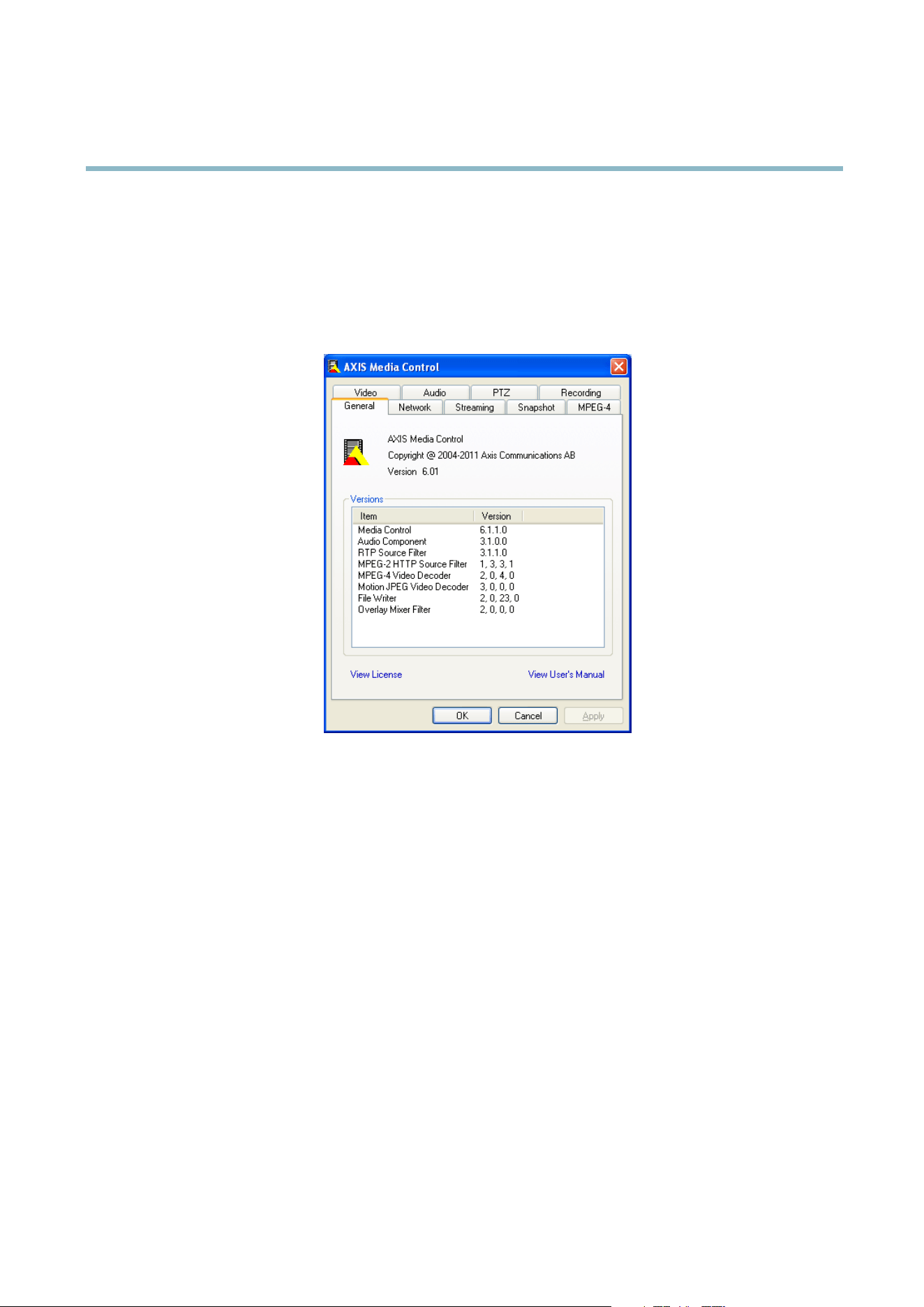
AXIS Media Control (AMC)
AXIS Media Control (AMC) in Internet Explorer in Window s is the recommended method of accessing live video from the Axis product.
11
AXIS P1214–E Network Camera
Media Strea ms
TheAMCControlPanelcanbeusedtoconfigure various video settings. Please see the AXIS Media Contro l User’s Manual for more
information.
The AMC Control Panel is automatically installed on first use, after which it can be configured. Open the AMC Control Panel from:
• Windows Co ntrol Panel (from the Start menu)
• Alternatively, right-click the video image in Internet Explorer and click Settings.
Alternative Methods of Accessing the Video Stream
You can also access video and images from the Axis product in the following ways:
• Motion JPEG server push (if supported by the client, Firefox, for example). This option maintains an open HTTP connection
to the brow s er and sends data as and when required, for as long as required.
• Still JPEG images in a browser.Enterthepathhttp://<ip>/axis-cgi/jpg/image.cgi
• Windows Media Player. This requires AXIS Media Control and the H.264 decoder to be installed. The following paths
can be u sed:
- Unicast via RTP: axrtpu://<ip>/axis-media/media.amp
- Unicast via RTSP: axrtsp://<ip>/axis-media/media.amp
- Unicast via RTSP, tunneled via HTTP: axrtsphttp://<ip>/axis-media/media.amp
-Multicast:axrtpm://<ip>/axis-media/media.amp
• QuickTime
TM
. The following paths can be used:
- rtsp://<ip>/axis-media/media.amp
- rtsp://<ip>/axis-media/media.3gp
12

AXIS P1214–E Network Camera
Media Strea ms
Note
• <ip>= IP addess
• The Axis product s upports QuickTime 6.5.1 and later.
• QuickTime adds latency to the video stream.
• It may be possible to use other players to view the H.264 stream using the paths above, although Axis does not guarantee
this.
13

AXIS P1214–E Network Camera
Setting Up the Product
Setting Up the Product
The Axis product can be configured by users with administrator or operator rights. To open the product’s Setup pages, click Setup in
the top right-hand corner of the Live View page.
• Administrators have unrestricted access to all settings.
• Operators have access to all settings except System O ptio ns
See also the online help
.
Basic Setup
Basic Setup provides shortcuts to the settings thatshouldbemadebeforeusingtheAxisproduct:
1. Users. See p age 30.
2. TCP/IP. See page 32.
3. Date & Time. See page 31.
4. Video Stream. See page 15.
The Basic Setup menu can be disabled from System Options > Security > Users.
14
AXIS P1214–E Network Camera
Video
Video
It is possible to configure the follo wing video features in yo ur Axis product:
• Video stream. See page 15.
•Streamprofiles. See page 16.
• Camera settings. See page 17.
• Overlay imag e. See page 17.
•Privacymask.Seepage 18.
Video Stream
You can define the following video stream settings from Video > Video Stream:
•Image.Seepage 16.
• H.264. See page 16.
•MJPEG.Seepage 16.
Pixel Counter
The pixel counter shows the number of pixels in an area of the image. The pixel counter is useful in situations where there is a
requirement that the ima ge is a certain size, for example in fa ce recognition.
The pixel counter can be accessed from:
• Video > Video Stream.UnderPreview,clickOpen and s elect the Show pixel counter option to enable the rectangle in
the image. Use the mouse to move and resize the rectangle, or enter the number of pixels in the Width and Height
fields and click Apply.
• The Live View page in Internet Explorer in Windo ws . Ri ght-click in the image and select Pixel counter.Usethemouse
to move and resize the rectangle.
15

AXIS P1214–E Network Camera
Video
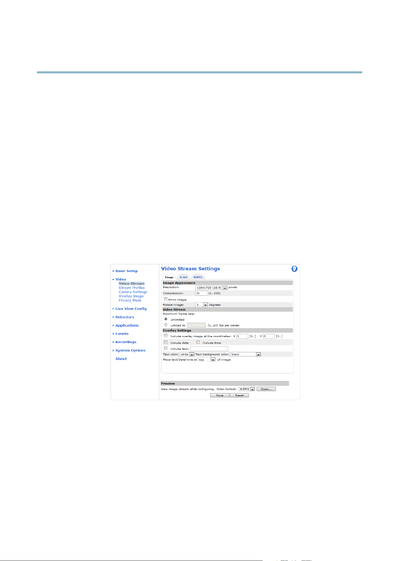
Image
The default image s ettings can be configured under Video> Video Stream. Select the Image tab.
The following settings are available:
• Resolution. Select the default resolution.
• Compression. The compression level a ffects the image quality, bandwidth and file size of saved images; the lower the
compression, the higher the image quality with higher bandwidth requirements and larger file sizes.
• Rotate image. If required, the image can be rotated.
• Mirror. If required, the image can be mirrored.
• Maximum frame rate. To avoid bandwidth problems, the frame rate allowed to each viewer can be limited.
• Overlay settings.SeeOverlay on page 17.
Click Save to apply the new settings.
H.264
H.264, also known as MPEG-4 Part 10/AVC, is a video compression s tandard that provides high q uality video streams at low bit rates.
An H.264 video stream consists of different types of frames such as I-frames and P-frames. A n I-frame is a complete image whereas
P-frames only contain the differences from previous frames.
The GOV length is the number of frames between two consecutive I-frames. Increasing the GOV length may save considerably on
bandwidth requirements in some cases, but may also have an adverse affect on image quality.
ThebitratecanbesetasVariable Bit Rate (VBR) or Constant Bit Rate (CBR). VBR adjusts the bit rate according to the image
complexity, using up more bandwidth for increased activity in the image, and less for lower image activity. CBR allows you to set a
fixed Target bit rate that consumes a predictable amount of bandwidth. As the
bit rate would usually need toincreaseforincreased
image activity, but in this case cannot, frame rate and image quality are affected negatively. To partly compensate for this, it is
possible to prioritize either frame rate or image quality. Not setting a priority means that frame rate and image quality a re equally
affected. You must save your settings b efore they can take effect.
The current bit rate can be set to appear as text overlay. To do
this, select the Include text check box option under Overlay
Settings and enter the modifier #b in the fi eld.
MJPEG
Sometimes the ima ge size is l arge due to low light or complex scenery. Adjusting the m a ximum frame size helps to control the
bandwidth and storage used by the
Motion JPEG video stream in these situations. Setting the frame size to the Default setting
provides consistently good image quality at the expense of increased bandwidth and storage usage in lo w light. Limiting the frame
size optimizes bandwidth and storage usage, but may give poor image quality. To prevent increased bandwidth and storage usage,
the maximum frame siz
e should be set to an optimal value.
Stream Profiles
There are four pre-programmed stream profiles availab le for quick se t up . The s ettings for thes e can be adjusted. New customized
profiles can also be created. Each profile has a descriptive name, indicating its purpose.
•Thestreamprofiles can be accessed from the Stream profile drop-down list in the Live View pag e.
• To add, copy, modify, and remove stream profiles go to Video > Stream Profiles.
• To select the default stream profi le go to Live View Config > Stream Profile and choose the profile from the drop-down list.
For more information see the online help
on this page.
16

AXIS P1214–E Network Camera
Video
Camera Settings
The Video > Camera Settings page provides access to advanced image settings for the Axis product.
Image Appearance
Increasing the Color level increases the color saturation. The value 100 gives m aximum color saturation. The value 0 gives a
black and white image.
The image Brightness can be adjusted in the range 0–100, where a higher value produces a brighter image.
Increasing the Sharpness can increase bandwidth usag e . A sharper imag e might increase image noise especia lly in low light
conditions. A lower setting reduces image noise, but the whole image will appear less sharp.
The Contrast changes the relative difference betwe en light and dark. It can be adjusted using the slidebar.
White Balance
White balance is used to make colors in the image appear the same regardless of the color temperature of the light source. The Axis
product can be set to automatically identify the light source and compensate for its color. Alternatively, select the type of light
source from the drop -dow n list. For a de scription of each available setting, see the online help
.
Exposure Settings
Configure the exposure s ettings to s uit t he image quality requirements in relation to lighting, frame rate and bandwidth
considerations.
Exposure value - Click in the bar to fine-tune the exposure.
Exposure control - These settings is used to adapt to the amount of light used. Automatic is the default settings can be used in most
situations. The shutter speed is automatically set to produce optimum image quality. Flicker-free 50 or 60 Hz is used to remove
flicker which can be caused by fluorescent and other light sources. The H old current option locks the current expo sure settings.
Enable Backlight compensation - Enable this option if a bright spot of light, for example a light bulb, causes other areas in
the image to appear too dark.
Exposure zones - This settings determines which part of the image is used to calculate the exposure. For most situations, the Auto
setting can be used. For particular requirement, select a predefined area.
Exposure priority - When Motion is prioritized and maximum Shutter time is se t to a small value, motion blur in the image is
minimized. This can be useful for recognition of moving objects such as people and vehicles. However, prioritizing motion may cause
an increase in image noise, especially in low light situations. When Low noise is prioritiz ed and Gain is set to a small value, image
noise is minimized. The file size is reduced, which can be useful if storage space or bandwidth is limited. However, prioritizing low
noise may result in a very dark image, especially in low light situations.
Overlay
Overlays are used to
provide extra informat ion, for example for forensic video analysis or during product installation and
configuration. Overlays are superimposed over the video stream.
An overlay text can display the cur rent date and time, or a text string. When using a text string, modifiers can be used to display
information such as the current bit rate or the current frame rate. For information about available modifiers, see File Naming &
Date/Time Formats in the online he lp
.
To enable overlays:
1. Go to Video > Video Stream and select the Image tab.
2. To include an overlay image, select Include overlay image at the coordinates. The overlay image must first be uploaded to
the A xis product, see Overlay Image.
17

AXIS P1214–E Network Camera
Video
3. To include date and time, select Include date and Include time.
4. To include a text string, select Include text and enter the text in the field. Modifiers can be used, see File Naming &
Date/Time Form ats in the o nline he lp
.
5. Select the text color, the text background color and the position of the overlay.
6. Click Save.
To modify the date and time format, go to System Options > Date & Time.SeeDate & Time on page 31.
Overlay I mage
An overlay image is a static image superimposed over the video stream. The image, for example company logo, is used to provide
extra info rmation or to mask a part of the image.
To use an overlay image, the imag e must first be uploaded to the Axis product:
1. Go to Video > Overlay Image.
2. Click Browse andbrowsetothefile.
3. Click Upload.
4. Select the image to use from the Use overlay image list.
5. Click Save.
To display the overlay image:
1. Go to Video > Video Stream and select the Image tab.
2. Under Overlay Settings,selectInclude overlay image at the coordinates and enter the X and Y coordinates.
3. Click Save.
For information about supported image formats, see the online help
.
Privacy Mask
A privacy mask is an area of solid color that prohibits users fro m viewing parts of the monitored area. Privacy masks cannot b e
bypassed via the VAPIX® Application Programming Interface (API).
The Privacy Mask List (Video > Privacy Mask) shows all the masks that are currently configured in the Axis product and indicates
if they a re ena
bled.
You ca
n add a new mask, re-size the mask with the mouse, choose a color for the mask, and give the mask a name.
For more i nformation, see the online help
Important
Adding many p rivacy masks may affect the product’s performance.
18
AXIS P1214–E Network Camera
Live View Config
Live View Config
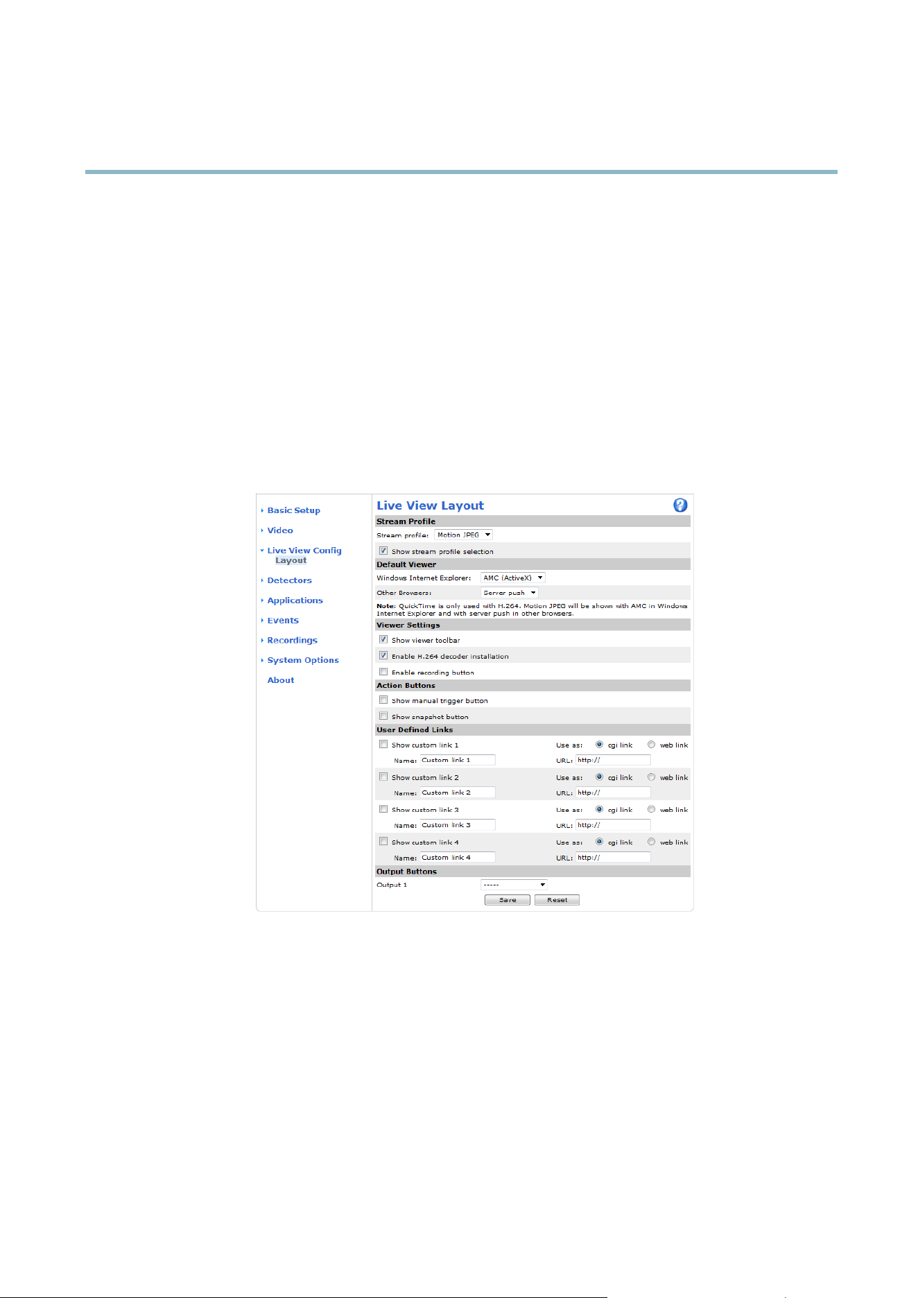
You can customize the Live View page and alter it to suit your requirements. It is possible to define the following features of
theLiveViewpage.
•StreamProfile. See page 16.
• Default Viewer for Browser. See page 19.
• Viewer Settings. See page 20.
• Action Buttons. These are the buttons described in Controls on the Live View Page on page 9 .
•UserDefined Links. See page 20.
• Output Buttons. See page 20.
Default Viewer for Browsers
From Live View Config > Default Viewer select the default method for viewing video images in your browser. The product attempts
to show the video images in the selected video format and viewer. If this is not possible, the product overrides the settings and
selects the best available combination.
19

AXIS P1214–E Network Camera
Live View Config
Browser Viewer Description
AMC
Recommended viewer in Internet Explorer (H.264/Motion JPEG).
QuickTime
H.264.
Java applet
A slower imaging alter n ative to AMC (Motion JPEG). Require s one of the
following installed on the client:
• JVM (J2SE) 1.4.2 or higher.
• JRE (J2SE) 5.0 or higher.
Windows Internet Explorer
Still image Displays still im ages only. Click the Refresh button in your browser to view a
new image.
Server Push
Recommended vi ewer for other brows ers (Motion JPEG).
QuickTime
H.264.
Java applet
A slower imaging alternative to Server Push (Motion JPEG only ).
Other browsers
Still image Displays still im ages only. Click the Refresh button in your browser to view a
new image.
For more information, please see the online help .
Viewer Settings
To configure options for the viewer, go to Live View Config > Viewer Settings.
•SelectShow viewer toolbar to display the AXIS Media Control (AM C) or the QuickTime viewer toolbar under the v ideo
image in your browser.
• H.264 decoder installation. The administrator can disable installation of the H.264 deco der included with AXIS Media
Control. This is used to prevent installation of unlicensed copies. Further decoder licenses can be purchased from your
Axis res eller.
•SelectEnable recording button to enable reco rding from the Live View page. This button is available when using
the AMC viewer. The recordings are saved to the location specified in the AMC Control Panel. See AXIS Media Control
(AMC) on page 11.
User Defined Links
To display user-defined links in the Live View page, select the Show custom link option, give the link a name and then enter the URL
to link to. When d efining a web link do not remove the 'http://' from the URL address. Custom links can be used to run scripts or
activate external devices connected to the product, or they can link to a web page. Custom links defined as cgi links will run the
script in the background, in a hidden frame. D efining the link as a web link will open the link in a new window.
Output Buttons
External I/O devices connected to the Axis product’s output ports can be controlled directly from the Live View page.
To display output buttons in the Live View page:
1. Go to Setup > Live View Config.
2. Under Output Buttons, select the type of control to use:
- Pulse activates the output for a defined period of time. The pulse time can be set from 1/100 second to 60
seconds.
- Active/Inactive displays two buttons, one or each action.
To configuretheactiveandinactivestates,gotoSystem Options > Ports & Devices > I/O Ports and set the port’s Normal state.
20


AXIS P1214–E Network Camera
Detectors
Detectors
Camera Tampering
Camera Tampering can genera te an alarm whenever the camera is repositioned, or when the lens is covered, sprayed or severely
defocused. To send an alarm, for example an email, an action rule must be set up.
To configure tamp ering:
1. Go to Detectors > Camera Tampering.
2. Set the Minimum duration, that is, the time that must elapse before an alarm is generated. This can help prevent false
alarms for known conditions that affect the image.
3. Select Alarm for dark images if an alarm should be generated if lights are dimmed or turned off, or if the lens is sprayed,
covered, or rendered severely out of focus.
4. Click Save.
To configure the pro duct to send an alarm when tampering occurs:
1. Go to Events > Action Rules.
2. Click Add to set up a new action rule.
3. Enter a Name for the action rule.
4. Under Condition,selectDetectors from the Trigger list.
5. Select Tampering from the list of detectors.
6. Optionally, select a schedule and set additional conditions.
7. Select the action. To send an email, select Send Notification a
nd select a Recipient from the list of defined recipients.
Note
The While the rule is active option under Duration cannot be used with camera tampering, since camera tampering does not
have a duration and once it has been triggered it will not automatically return to its untriggered state.
For more information on actions rules, see Events on page 25.
Motion Detection
Motion detection is used to generate an alarm when ever movement starts or stops in the camera view.
Motion detection i s configured by defining up to 10 Include and Exclude windows:
• Include windows —define areas where motion should be detected
• Exclude windows —define areas within an Include window that should b e ignored (areas outside Include w indows
are automatically ignored).
For instructions, see Set Up Motion Detection Windows on page 23.
To control the number of motion detection alarms, the parameters Object Size, History and Sensitivity can be adjusted. See
Motion Detection Parameters on page 23.
Once motion detection windows are configured, the Axis product can be configured to perform actions when motion is detected.
Possible actions include uploading images and start recording. For more information, see Setting Up an Actio n Rule on page 26.
22

AXIS P1214–E Network Camera
Detectors
Note
Using the motion detection feature may decrease the product’s overall performance.
Set Up Motion Detection Windows
To set up a motion detection Include Window, follow these instructions :
1. Go to Detectors > Motion Detection.
2. Select the Configure Included Windows option and click New. Se lect the new window in the list of window s and enter
adescriptivename.
3. Adjust the size (drag the bottom right-hand corner) and the position (click on the text at the top and drag to the desired
position) of the window.
4. Adjust the Object Size, History and Sensitivity profile sliders (see Motion Detection Parameters for details). Any detected
motion within an active window is indicated by red p eaks in the Activity window.
5. Click Save.
To exclude parts of the include window, select the Configure Excluded Windows and position the exclude window within the
include window.
To delete an include or exclude window, s elect the window in the list of windows and click Del.
Motion Detection Parameters
The parameters controlling motion detection are described in the table below:
Parameter
Object Size
History
Sensitivity
Description
Object size relative to window
size.
Object memory length.
Difference in luminance
between background and
object.
High level (100%)
Only very large objects trigger
motion detection.
An object that appears in
the window triggers motion
detection for a long time
before it is considered as
non-moving.
Ordinary colored objects on
ordinary backgrounds trigger
motion detection.
Medium level (50%)
A large difference in luminance
is required to trigge r m otion
detection.
Low level (0%)
Even very small objects trigger
motion detection.
An object that appears in
the window triggers motion
detection only for a very short
time before it is considered as
non-moving.
Only ver y bright objects on
a dark background tri
gger
motion detection.
Recommended values
5–15% 60–90% 75–95%
Default values
15% 90% 90%
Note
• To trigger on small objects or movements, use several small motion detection windows rather than one large window
and s elect a low object size.
• To avoid triggering on small objects, select a high object size.
• If no objects should appear in the Include Window, select a high history level. This will cause motion detection to
trigger as long as the object is present in the window.
• To only detect flashing light, select a low sensitivity. In other cases high sensitivity is recommended.
23

AXIS P1214–E Network Camera
Applications
Applications
Third party ap plications can be uploaded to and installed on the Axis product. For information a bout available applications,
downloads, trials and licenses, go to www.axis.com/applications
To upload an application, go to Applications > O verview, click Browse to locate the file and then click Upload Package. Click on the
uploaded application’s name to open the menu options Settings, License and About.Forconfiguration instructions, please refer to
the documentation provided with the application.
Most applications need a license to run. To install the license, select the License menu option. If the product is connected
to the Internet, Automatic Installation appears in the web page. If the product is not connected to the Internet, go to
www.axis.com/applications to acquire a License key. You will need a license code and the product’s serial number (found on the label
and under System Options > Support > System Overview ) to receive a license key.
Installed Applications lists installed applications with information about the version and the vendor, the status of the applica tion
(running or not running), and information about the license.
Use the Start and Stop buttons to start and stop the application.
To generate a log file for the application, select the application and click Log.
Note
It is recommended to run one application at a time. A void running applicatio ns when motion detection is active.
24

AXIS P1214–E Network Camera
Events
Events
The Axis product can be configured to perform actions when diffe rent events occur, for example, start a recording when motion i s
detected. The set of conditions that defines how and when the action is triggered is called an Action Rule.
Available Action Rule triggers and conditions include:
• Applications — use installed applications to trigger the rule, s ee Applications on page 24.
• Detectors
- Motion Detection — trigger the rule when motion is detected, see Motion Detection on page 22.
- Tampering — trigger the rule when tampering is detected, see Camera Tampering on page 22.
• Hardware
- Network — trigger the rule if network connection is lost or restored. This can for example be used to start
recording to the SD card.
• Input Signal
- Digital Input Port — trigger the rule when a n I/O port receives a signal from a connected device, see I/O
Ports on page 38.
- Manual Trigger — trigger the rule using the Manual Trigger button in the Live View page, see Controls on
the Live View Page on page 9 . This can for e xa mple be use d to validate actions dur ing product installation
and configuration.
• Storage
- Available — trigger the rule when the storage device is unmounted or removed. This can for example be
used to send maintenance notifications.
- Full — trigger the rule when the storag e device is full. U nder normal operation, the oldest recor dings will be
overwritten to prevent the storage device from becomin
g full.
- Locked —triggertheruleifthestoragedeviceis
locked (write protected).
• System
- System Initializing —tr
igger the rule when the product is being started. This can for example be used to send a
notification when the product restarts.
• Time
- Recurrence — trigger the rule periodically, see Recurrences on page 27. This can for example be used to upload
an image every 5 minutes.
- Use Schedule — trigger the rule according to the selected schedu le, see Schedules on page 27.
Available actions include:
• Output Port — activate an I/O port to control an external device.
• Record Video — record video to a selected storage.
• Send Images —sendimagestoarecipient.
• Send Notifications —sendanotificatio n message to a recipient.
• Status LED — flash the LED indicator. This can fo r example be used to validate triggers such as motion detection during
product installation and configuration.
25

AXIS P1214–E Network Camera
Events
Setting Up an Action Rule
An action rule defines the conditions that m u st be met for the product to perform an action, f or examp le record video or send email
notifications. If multiple conditions are defined, all must be met to trigger the action.
The following example describes how to set up an action rule to record video to a network share if there is mo vement in the
camera’s field o f view.
Set up motion detection and a dd a network share:
1. Go to Detectors > Motion Detection and configure a motion detection window, see page 23
2. Go to System Options > Storage and set up the network share, see page 38.
Set up the action rule:
1. Go to Events > Action Rules and click Add.
2. Select Enable rule and enter a descriptive name for the rule.
3. Select Detectors from the Trigger drop-down list.
4. Select Motion Detection from the drop-down list. Select the motion detection window to use.
5. Optionally, select a Schedule and Additional conditions,seebelow.
6. Under Actions, select Record Video from the Ty pe drop-down list.
7. Select a Stream profile and configure the Duration settings as described below.
8. Select Network Share from the Storage drop-down list.
To add additional criteria, s elect the Additional conditions option and a dd additional triggers. To p revent an action from being
triggered repeatedly, a Wait at least time can b e set. Enter the
time in hours, minutes and seconds, during which the trigger
should be ignored before the action rule can be activated again.
The recording Duration of some actions can be set t o include time immediately before and after the event. Select Pre-trigger time
and/or Post-trigger time and enter the number of seconds. When While the rule is active is enabled and the action is triggered
again during the post-trigger time, the record
ing time will be extended with another post-trigger time period.
For m ore information, see the o nline help
.
Recipients
Recipients receive media files and notification mess ages. The fo llowing recipients are avail able :
Recipient Use with ac
tion
Email
Send Images
Send Notification
FTP
Send Images
HTTP
Send Images
Send Notification
Network Share Send Images
TCP Send Notification
26

AXIS P1214–E Network Camera
Events
Note
A network share can also b e used as a storage device for recorded video. Go to System Options > Storage to configure a
network share before setting up a continuous recordingoranactionruletorecordvideo. SeeStorage on page 37 for more
information about storage devices.
To add a recipient:
1. Go to Events > Recipients a n d click Add.
2. Enter a descriptive name.
3. Select a recipient Type.
4. Enter the information needed for the recipient type.
5. Click Test to test the connection to the recipient.
6. Click OK.
Schedules
Schedules can be used as action rule triggers or as additional conditions, for example to record video if motion is detected outside
office hours. Use one of the predefined schedules or create a new schedule as described below.
To create a new schedule:
1. Go to Events > Schedules and click Add.
2. Enter a descriptive name and the information needed for a daily, wee kly, monthly or yearly schedule.
3. Click OK.
To use the schedule in an Action Rule, select the schedule from the Sche
dule drop-down list i n the Action Rule Setup page.
Recurrences
Recurrences are used to trigger Actio
n Rules repeat edly, for example ev ery 5 minutes or every hour.
To set up a recurrence:
1. Go to Events > Recurrences
and click Add.
2. Enter a descriptive
name and recurrence p attern.
3. Click OK.
To use
therecurrenceinanActionRule,first select Time from the Trigger drop-down list in the Action Rule Setup page and
then select the recurrence from the second drop-down list.
To modify or remove recurrences, selec t the r ecurrence in the Recurrences List and click Modify or Remove.
27

AXIS P1214–E Network Camera
Recordings
Recordings
TheAxisproductcanbeconfigured to record video continuously or according to an action rule:
• To start a continuous recording, see page 28.
• To set up action rules, see page 26.
• To access recordings, see Recording List on page 28.
•Toconfigure camera controlled storage, see Storage on page 37.
Recording List
Recorded videos are listed on the Recordings > List page. The list shows each recording’s start date and time, duration and the
event that triggered the recording.
To play or download a recording, follow these steps:
1. Go to Recordings > List.
2. Use the filter to narrow the list of recordings. Enter the desired fil ter criteria and click Filter. Some filters may take
a long time t o complete.
3. Select the recording.
4. Click Play to play the recording, or click Download to download the recording.
Multiple recordings can be downloaded at the same time. Select the recordings and click Download. The downloaded file is a zip file
containing a minimum of three files, of which the Matroska (mkv) files a re the actual recordings. The recordings are time-stamped
with the date and time they were downloaded (that is, not the date the
recordings were made).
Note
To play record ings in Windows Media Player, AXIS Matroska File Splitter must be installed. AXIS Matroska File Splitter
can be downloaded from www.axis.com/techsup/software
For detailed recording and video information, select a recording and click Properties.
To remove a recording, select the recording and click Remove.
Continuous recording
The Axis product can be configured to continuously save video to an SD card or network share. To prevent the disk from becoming
full, it is recommended to configure the disk to automatically remove old recordings see Storage on page 37.
To start a continuous recording, follow these steps:
1. Go to Recordings > Continuous.
2. Select Enabled.
3. Select from the SD card or network share from the Disk list.
4. Select a Stream profile to use for continuous recordings.
5. Click Save to save and start the recording.
28

AXIS P1214–E Network Camera
Recordings
Note
If a new stream profile is selected while a recording is ongoing, the recording will be stopped and saved in the reco rding list
and a new recording with the new stream profile will start. All previous continuous recordings will remain in the recording
list until they are removed manually or through automatic removal of old recordings.
29

AXIS P1214–E Network Camera
System Options
System Options
Security
Users
User access control is enabled by default and can be configured under System Options > Security > Users. An administrator can
set up other users by giving them user names and passwords. It is also possible to allow anonymous viewer login, which means
that anybody may access the Live View page.
The user list displays authorized users and user groups (access levels):
Viewer - Access to the Live View page
Operator - Access to the Live View page and to all settings except System Options
Administrator - Unrestricted access to all settings; can add, modify and remove other users.
Under HTTP/RTSPPasswordSettings, select the type of password to allow. You may need to allow unencrypted passwords if there
are viewing clients that d o not support encryption, or if you upgraded the firmware and existing clients support encryption but need
to log in again and be c onfiguredtousethisfunctionality.
Under User Settings, select the Enable anonymous viewer login option to allow anonymous users access to the Live View page.
Deselect the Enable Basic Setup option to hide the Basic Setup menu. Basic Setup provides quick access to settings that should be
made before using the Axis prod uct.
ONVIF
ONVIF (Open Network Video Interface Forum) is a global inte rface sta ndard that makes it easier for end users, integrators , consultants,
and manufacturers to take advantage of the possibilities offered by network video technology. ONVIF enables interoperablity between
different vendor products, increased flexibility, reduced cos
t and future-pro of systems.
By creating a user you au toma tically enable ONVIF commu
nication. Use the user name and password with all ONVIF communication
with the product. For more information see www.onvif.org
IP Address Filter
IP address filtering is enabled on the System Options > Security > IP Address Filter page. Once enabled, the listed IP address are
allowed or denied access to th
e Axis product. Select Allow or Deny from the li st and click Apply to enable IP address filtering.
The administrator can a
dd up to 256 IP address entries to the list (a single entry can contain multiple IP addresses).
HTTPS
The Axis product supports encrypted browsing using HTTPS. This is configured on the System Options > Security > HTTPS page.
A self-signed certificate can be used until a Certificate Authority-issued certificate has been obtained. Click Create self-signed
certificate to install a self -signed certificate. Although self-signed certificates are free and offer some protection, true security is o nly
impl
emented after the installatio n of a signed certifica te issued by a Certificate Authority.
To obtain a signe d certificate from an issuing Certificate Authority, click Create Certificate Request. When the signed certificate
is returned, click Install signed certificate to import the certificate. The properties of any certificate request currently resident in
the product or installed can be viewed by clicking Properties.
To enable HTTPS in the Axis product, the HTTPS C onnection Policy must be set for each user group.
For more i nformation, see the online help
.
30

AXIS P1214–E Network Camera
System Options
IEEE 802.1X
IEEE 802.1X is a s tandard for port-based Network Admission Control providing secure authentication of wired and wireless network
devices. IEEE 802.1X is based on EAP (Extensible Authentication Protocol).
To access a network protected by IEEE 802.1X, devices must authenticate themselves. The authentication is performed by a
third-party entity called an authentication server, typically a RADIUS server, examples of which are FreeRADIUS and Microsoft
Internet Authentication Service.
In Axis' implem enta tion, the network device and the authentication server authenticate themselves with the help of digital
certificates using EAP-TLS (Extensible Authentication Protocol - Transport Layer Security). The certificates are provided by an
Certification Authority (CA). You need:
•aCAcertificate to validate the identity of the authentication server
• a CA-signed clie nt certificate and a private key to authenticate the network device.
To allow the network device to access a network protected by IEEE 802.1X:
1. Obtain a CA certificate, a client certificate and a client private key (contact your network administrator).
2. Go to Setup > System Options > Security > IEEE 802.1X and upload the CA certificate, the client certificate and the
client private key.
3. Under Settings, select the EAPOL version, provide your EAP identity and private key password.
4. Check the box to enable IEEE 802.1X and click Save.
Certificates
CA Certificate The CA certificate is used to validate the identity of the authentication server. Enter the path to
the certificate directly, or lo cate the file using t he Browse button. Then click U
pload.Toremove
acertificate , click Remove.
Client certificate
Client private key
The client certificate and private key are used to authenticate the network device. They can be
uploaded as separate files or in one combined file (e.g. a PFX file or a PEM file). Use the Client
private key field if uploading one combined file. For each file, enter the path t o the file, or locate the
fi
le using the Browse button. Then click Upload.Toremoveafile, click Remove.
Settings
EAPOL version
SelecttheEAPOLversion(1or2)asusedinyournetworkswitch.
EAP identity
Enter the user identity (maximum 16 characters) associated with your certificate.
Private key password
Enter the password (maximum
16 characters) for the private key.
Enable IEEE 802.1X
Check the box to enable the IEEE 802.1X protocol.
Date & Time
The Axis product’s date and time s ettings are configured under System Options > Date & Time.
Current Server Time displays the current date and time (24h clock). The time can be displayed in 12h clock in the text overlay (see
below).
To change the date a nd time settings, select the preferred Time mode under New Server Time:
• Synchronize with computer time sets date and time according to the com puter’s clock. With this option, date and
time are set once and will not be upd ated automatically.
• Synchronize with NTP Server obtains date and time from an NTP server. With this option, date and time settings are
updated continuously. For information on NTP settings, see NTP Configuration on page 34.
31

AXIS P1214–E Network Camera
System Options
If using a host name for the NTP server, a DNS server must be configured. See DNS Configuration on page 34.
• Set m anually allows you to ma nually set date and time.
If using an NTP server, select your Time zone from the drop-down list. If required, check Automatically adjust for daylight saving
time changes.
The Date & Time Format Used in Images is the date and time format displayed as a text overlay in the video stream. Use the
predefined formats or see File Naming & Date/Time Formats in the online help
for information on how to create custom date and
time formats. To include date a nd time in the overlay text, go to Video and select Include date and Include time.
Network
Basic TCP/IP Settings
The Axis product supports IP version 4 and IP version 6. Both versions can be enabled simultaneo usly, and at least one version
must always be enabled.
IPv4 Address Configuration
By default, the Axis product is set to use IPv4 (IP version 4) and to obtain the IP address automatically via DHCP. The I Pv4 settings are
configured under System Options > Network > TCP/IP > Basic.
DHCP (Dynamic Host Configuration Protocol) allows network administrators to centrally manage and automate the assignment of
IP addresses. DHCP should only be enabled if using dynamic IP a ddress notification, or if the DHCP can update a DNS server. It is
then possible to access the Axis product by name (host name).
If DH CP is enabled and the product cannot be accessed, run AXIS IP Utility to search the network for connected Axis products, or reset
the product to the factory default settings (see page 40) and then perform the installation again.
To use a static IP address, check Use the following IP address and specify the IP add ress, subnet mask and default router.
IPv6 Address Con figuration
If IPv6 (IP version 6) is enabled, the Axis product will receive an IP address according to the configuration in the network router.
To enable IPv6, go to System Options > Network > TCP/IP > Basic. Other settings for IPv6 should be configured in the network router.
ARP/Ping
The product’s IP address can be assigned using ARP and Ping. For instructions, see Assign IP Address using ARP/Ping on page 32.
The ARP/Ping service is enabled by default but is automatically disa bled two minutes after the product is started, or as soon as an IP
address is assigned. To re-assign IP a ddress using ARP/Ping, the pro duct must be restarted to enable ARP/Ping for an additional
two minutes.
To disable the service, go to System Options > Network > TCP/IP > Basic and clear the option Enable ARP/Ping setting of IP address.
Pinging the product is still possible when the service is disabled.
Assign IP Address using ARP/Ping
The product's IP address can be assigned using ARP/Ping. The command must be issued within 2 minutes of connecting p ower.
1. Acquire a fre e static IP address on the same network s egment as the computer.
2. Locate the serial number (S/N ) on the product label.
3. Open a command prompt and enter the following commands:
32

AXIS P1214–E Network Camera
System Options
Linux/Unix syntax
arp -s <IP address> <serial number> temp
ping -s 408 <IP address>
Linux/Unix example
arp -s 192.168.0.125 00:40:8c:18:10:00 temp
ping -s 408 408 192.168.0.125
Windows syntax (this may require that you run the command prompt as an administrator)
arp -s <IP address> <serial number>
ping -l 408 -t <IP address>
Windows example (this may require that you run the command prompt as an administrator)
arp -s 192.168.0.125 00-40-8c-18-10-00
ping -l 408 -t 192.168.0.125
4. Check that the network cable is connected to the Axis product and then restart the product by disconnecting and
reconnecting power.
5. Close the command prompt when the product responds with Reply from 192.168.0.125:... or similar.
6. Open a browser and type http://<IP address> in the Location/Address field.
For other methods of assigning the IP address, see the Installation and Management Software CD or the document Assign an IP
Address and Access the Video Stream on Axis Support web at www.axis.com/techsup
Note
• To open a command prom pt in Windows, op en the Start menu and type cmd in the Run/Search field.
• To use the ARP command in Window s 7/W indows Vis ta, right-click the com mand prompt icon and select Run as
administrator.
• To open a command prompt in Mac OS X, open the Terminal utility from Application > Utilities.
AXIS Video Hosting System (AVHS)
AVHS used in conjunction with an AVHS service, provides easy and secure Internet access to live and recorded video accessible from
any location. For more information and help to find a local AVHS Service Provider go to www.axis.com/hosting
AVHS is enabled by default. The settings are configured under System Options > Network > TCP IP > Basic.
One-click enabled - Press the product’s control button ( see Hardware Overview on page 4 ) to connect to an AVHS service over the
Internet. Once registered, Always will be enabled and the Axis product stays connected to the AVHS service. If the product is not
registered within 24 hours from when the button is pressed, the product will disconnect from the AVHS service.
Always - The Axis product will constantly attempt to connect to the AVHS service over the Internet. Once registered the product will
stay connected to the service. This option can be used when the product is already installed and it is not convenient to use the
one-click installation.
AXIS Internet Dynamic DNS Service
AXIS Internet Dynamic DNS Service assigns a host name for easy ac ce s s to the product. For more information, see www.axiscam.net
To register the A xis product with AXIS Interne t Dynamic DNS Service , go to System Options > Network > TCP/IP > Basic.Under
Services, click the AXIS Internet Dynamic DNS Service Settings button (requires access to the Internet). The domain name currently
registered at AXIS Internet Dynamic DNS service for the product can at any time be removed.
33

AXIS P1214–E Network Camera
System Options
Advanced TCP/IP Settings
DNS Configuration
DNS (Domain Name Service) provides the translation of host names to IP addresses. The DNS settings are configured under System
Options > Network > TCP/IP > Advanced.
Select Obtain DN S server address via DHCP to use the DNS settings provided by the DHCP server.
To make manual settings, select Use the following DNS server address and specify the following:
Domain name - Enter the domain(s) to search for the host name used by the Axis product. Multiple domains ca n be separated by
semicolons. The host name is always the firstpartofafullyqualified domain name, for example, myserver is the host name in the
fully qualified domain name myserver.mycompany.com where mycompany.com is the domain name.
Primary/Secondary DNS server - Enter the IP addresses of the primary and secondary DNS servers. The seconda ry DNS server is
optional a nd will be used if the primary is unavailable.
NTP Configuration
NTP (Network Time Protocol) is used to synchronize the clock times of devices in a network. The NTP settings are configured under
System Options > Network > TCP/IP > Advanced.
Select Obtain NTP server address v ia DHCP to use the NTP settings provided by the DHCP server.
To make manual settings, select Use the following NTP server address and enter the host name or IP address of the NTP server.
Host Name Configuration
The Axis product can be accessed using a host name instead of a n IP address. The host name is usually the same as the assigned DNS
name. The host name is configured under System Options > Network > TCP/IP > Advanced.
Select Obtain host name via IPv4 DHCP to use host name provided by the DHCP server running on IPv4.
Select Use the host name to set the host name manually.
Select Enable dynamic DNS updates to dynamically update local DNS servers whenever the Axis product’s IP address changes.
For m ore information, see the o nline help
.
Link-Local IPv4 Address
Link-Local Address is enabled by default and assigns the Axis product an additional IP address w hich can be used to access
the product from other hosts on the same segment on the local network. The product can have a Link-Local IP and a static
or DHCP-supplied IP address at the sam e time .
This function can be disable d under System Options > Network > TCP/IP > Advanced.
HTTP
The HTTP port used by the Axis product can be changed under System Options > Network > TCP/IP > Advanced. In addition to the
default setting, which is 80, any port in the range 1024–65535 can be used.
HTTPS
The HTTPS port used by the Axis product can be changed under System Options > Network > TCP/IP > A dvanced. In addition to
the default setting, which is 443, any port in the range 1024–65535 can be used.
To enable HTTPS, g o to System Options > Security > HTTPS. For more information, see page 30.
34

AXIS P1214–E Network Camera
System Options
NAT traversal (port mapping) for IPv4
A network router allows devices on a private network (LAN) to share a single connection to the Internet. This is done by forwarding
network traffic from the private network to the “outside”, that is, the Internet. Security on the private netw ork (LAN) is increased
since most routers are pre-configured to stop attempts to access the private network (LAN) from the public network (Internet).
Use NAT traversal w h e n the Axis product is located on an intranet (LAN ) and you wi sh to make it availa ble from t he other
(WAN) side of a NAT router. With NAT tra versal properly configured, all HTTP traffic to an external HTTP port in the NAT router
isforwardedtotheproduct.
NAT traversal is configured under System Options > Network > TCP/IP > Advanced.
Note
• For NAT tra versal to work, this must be supported by the router. The router must also supp ort UPnP
TM
.
• The router has many different names: “NAT route r”, “Network router”, “Internet Gateway”, ”Broadband router”, “Broadband
sharing device” or “Home firewall” but the essential purp ose of the device is the same.
Enable/Disable - When enabled, the A xis product attempts to configure port mapping in a NAT router on your network, using U PnP
TM
.
Note that UPnP
TM
must be enabled in the product (see System Options > Network > UPnP).
Use manually selected NAT router - Select this option to manually select a NAT router and enter the IP address for the router in
the field. If no router is specified, the product automatically searches for NAT routers on you r network. If more than one router is
found, the default router is selected.
Alternative HTTP port - Select this option to manually define an external HTTP port. Enter the port num ber in the field. If no port is
entered here , a port number is automatically selected when NA T traversal is enabled.
Note
• An alternative HTTP port can be used or be active even if NAT traversal is disabled. This is useful if your NAT router does
not support UPnP and you need to manually configure port forwarding in the NAT router.
• If you attempt to manually enter a port that is already in use, another available port is automatically selected.
• When the port is sele cted automatically it is displayed in this field. To change this, enter a new port number and click Save.
FTP
The FTP server running in the Axis product enables upload o f new firmware, user applications, etc. The FTP server can be disabled
under System Options > Network > TCP/IP > Advanced.
Note
This FTP server has nothing to do with the product’s ability to transfer images via FTP to other locations and servers.
RTSP
The RTSP server running in the Axis product allows a connecting client to start an H.264 stream. The RTSP port number can be
changed under System Options > Network > TCP/IP > Advanced. The default port is 554.
Note
H.264 video streams will not be ava ilable if the RTSP server is disabled.
SOCKS
SOCKS is a networking proxy protocol. The Axis product can b e configured to use a SOCKS server to reach networks on the other
side of a firewall or proxy server. This functionality is useful if the Axis product is located on a local network behind a firewall, a nd
notifications, uploads, alarms, etc need to be sent to a destination outside the local network (for example the Internet).
SOCKS is configured under System Options > Network > SOCKS. For more information, see the online help
.
35

AXIS P1214–E Network Camera
System Options
QoS (Quality of Service)
QoS (Quality of Service) guarantees a certain level of a specified resource to selected traffic on a network. A QoS-aware network
prioritizes network traffic and provides a greater network reliability by controlling the amount of bandwidth an application may use.
TheQoSsettingsareconfigured under System Options > Network > QoS. Using DSCP (Differentiated Services Codepoint) values, the
Axis product can mark the following types of traffic: live video, event/alarm traffic and management traffic.
SMTP (email)
To send email messages from the Axis product via SMTP (Simple Mail Transfer Protocol), an SMTP mail server must be set up. This
is done under System Options > Network > SMTP (email).
Enter the host names or IP addresses and port numbers for the primary and secondary mail servers in the fields pro vided . A From
email address is also r equi red. If the mail serve r requires authentication, check Use authentication to log in to this server and enter
the necessary information.
SNMP
The Simple Network Management Protocol (SNMP) allows remote management of network devices. An SNMP community is the
group of devices and management station running SNMP. Community names are used to identify groups.
The Axis product can be configured to s upport SNMP on the System Options > Network > SNMP page.
Depending on the level of security required, select the version on SNMP to use.
SNMP v1/v2 provides the lowest level of security. The community name can be specifi ed as a password for read or read/write
access to all supported SNMP devices. The default password for the Read community is public and the default password for the
Write community is write.
Note
If HTTPS is enabled, SNMP v1 and SNMP v2c s hould be disabled.
Traps for SNMP v1/v2 are used by the Axis product to send messages to a manageme n t sy
stem on important events and status
changes. Check Enable traps and enter the IP address where the trap message should be sent and the Trap community that
should receive the message.
The following traps are available:
•Coldstart
•Warmstart
•Linkup
• Authentication failed
SNMP v3 provides encryption and secure passwords. To use traps with SNMP v3, an SN MP v3 management application is required.
To use SNMP v3, HTTPS must be enabled, s ee HTTPS on page 30. To enable SNMP v3, check the box and provide the initial user
password.
Note
The initial password can only be set once. If the password is lo st, the Axis product must be reset to factory default, see
Reset to Factory Default Settings on page 40.
UPnP
TM
The Axis product includes support for UPnP
TM
.UPnP
TM
is enabled by default and the product is automatically detected by operating
systems and clients that support this protocol.
UPnP
TM
can be disable d under System Options > Network > UPnP
TM
.
36

AXIS P1214–E Network Camera
System Options
RTP/H.264
The RTP port range and multicast settings are configured under System Options > Network > RTP.
The RTP port range defines t he range of po rts from which the video ports are automatically selected. For multicast streams, only
certain IP addresses and port numbers should be used.
Select Always Multicast Video to start multicast streaming without opening an RTSP session.
Bonjour
The Axis product includes support for Bonjour. Bonjour is enabled by default and the product is automatically detected by op erating
systems and clients that support this protocol.
Bonjour can be disabled under System Options > Network > Bonjour.
Storage
SD Card
NOTICE
To prevent corruption of recordings, the SD card should always be unmounted befo re it is ejected.
The Axis product supports SD cards with the following file systems:
• ext4 — recommended due to its resi lie nce against data loss if the card is ejected or if there is abrupt power loss. To access
data stored on the card from the Windows operating system, a third-party ext4 driver or application is r equired.
• vFAT — most SD cards are pre-formatted with vFAT when purchased.
If required, the SD card can be re-formatted to the desired file system. To format the SD card:
1. Insert the SD card in the SD card slo t.
2. Go to System Options > Storage an d click SD Card.
3. Click Format and select the desired file system.
Note
During formatting any previous data stored on the disk will be lost.
Mounting is done automatically when the card is inserted or when the product is started. A manual mount is only required if the
card has been unmounted and not ejected and re-inserted.
To unmount the SD card:
1. Go to System Options > Storage an d click SD Card.
2. Click Unmount.
3. The card can now be re move d.
The SD card is managed on the System Options > Storage page. Click SD Card to open Storage Management.
If the card’s status s hows as failed, click Check disk to see if the problem can b e found and then try Repair. This option is only
available for SD cards with ext4. For SD cards with vFAT, use a card reader or computer to troubleshoot the card.
To avoid filling the card, it is recommended to remove recordings continuously. Under Recording Settings, select Remove recordings
older than and select the number of days or weeks.
To stop writing to the card and protect recording s from being removed, select Lock under Recording Settings.
37

AXIS P1214–E Network Camera
System Options
Network Share
Network share allows you to add network storage such as a NAS (Network Attached Storage) or any server that uses CIFS (Common
Internet File System) and use them for storage of recordings.
To add a network share:
1. Go to System Options > Storage.
2. Click Network Share.
3. Enter the IP address, DNS or Bonjour name to the host server in the Host field.
4. Enter the name of the share in the Share fiel d.
5. If required, select The share requires login and enter the user n ame and password.
6. Click Connect.
To clear all recordings and data from the Axis product’s folder on the designated share, click Clear under Storage Tools.
To avoid filling the share, it is recommended to remove recordings continuously. Under Recording Settings,selectRemove recordings
older than and select the number of days or weeks.
To stop writing to the share and protect recordings from being removed, select Lock under Recording Settings.
Ports & Devices
I/O Ports
The Axis product provides one input port and one output port for connection of external devices. For information on how to
connect external devices, see Connectors on page 4 .
The I/ O ports are configured under System Options > Ports & Devices > I/O Ports. The ports can be given descriptive names and their
Normal states can be configured as Open circuit or Grounded
circuit.
Port Status
The list on the System Options > Ports & Devices > Port Status page shows the status of the product’s input and output ports.
Maintenance
The Axis product provides several maintenance functions. These are available under System Options > Maintenance.
Click Restart to perform a correct restart if the Axis product is not behaving as expected. This will not affect any of the current
settings.
Click Restore to reset most settings to the factory default values. The following settings are not affected:
• the boot protocol (DHCP or static)
• the static IP address
• the default router
• the subnet mask
•thesystemtime
• the IEEE 802.1X settings
38

AXIS P1214–E Network Camera
System Options
Click Default to reset all settings, including the IP address, to the factory default values. This button should be used with caution. The
Axis product can also be reset to factory default using the control button, see Reset to Factory Default Settings on page 40.
To identify the product or test the Status LED, click Flash LED under Identify and specify the duration in seconds, minutes or hours.
This can be useful for identifying the product among other products installed in the same location.
For information about firmware upgrade, see Upgra ding the Firmware o n page 41.
Support
Support Overview
The System Options > Support > Support Overview page provides information on troubleshooting and contact information,
should you require technical assistance.
See a lso Troubleshooting on page 41.
System Overview
To get an overview of the Axis product’s status and settings, go to System Options > Support > System Overview. Information that
can be found here includes firmware version, IP address, network and security settings, event settings, image s ettings and recent log
items. Many of the captions a re links to the proper Setup page.
Logs & R eports
The System Options > Support > Logs & Reports page generates logs and reports useful for system analysis and troub leshooting. If
contacting Axis Support, please provide a valid Server Report with y our query.
System Log - Provides information about system events.
Access Log - Lists all failed attempts to access the product. The Access Log can als
obeconfigured to list all connections to the
product (see below).
Server Report - Pro v ides information about the product status in a pop -up window. The Access Log is automatically included
in the Server Report.
You can view or download the server report. Downloading the server report creates a .zip file that contains a complete server report
text file in UTF–8 format. Select the Include snapshot with default image settings option to include a snapshot of the product’s
Live View that also shows the settings specified under Video Stream>Image>Image Appearance. The server report .zip file should
always be included when contacting support.
Parameter L ist - Shows the product's parameters and their current settings. This may prove useful when troubleshooting or
when contacting Axis Suppo rt.
Connection List - List s all clients that are curre ntly acces sing media streams.
Crash Report - Generates an archive with debugging in forma tion. The report takes several minutes to generate.
The log levels for the System Log and the Access Log are set under System Options > Support > Logs & Reports > Configuration.
The Access Log can be configured to list all connections to the product (select Critical, Warnings & Info). If required, a different log
level c
an be used when sending emails.
Advanced
Scripting
Scripting allows experienced users to customize and use their own scripts.
39

AXIS P1214–E Network Camera
System Options
NOTICE
Improper use may cause unexp ected behavior and loss of contact with the Axis product.
Axis strongly recommends that you do not use this function unless y ou understand the consequences. Axis Support does not provide
assistance for problems with customized scripts.
To open the Script Editor, go to System Options > Advanced > Scripting. It is recommended to create a backup file before
customizing the scripts. If a script causes problems, reset the product to its factory default settings, see page 40.
For more information, s ee www.axis.com/developer
File Upload
Files, for example web pages and images, can be uploaded to the Axis product and used as custom settings. To up load a file, go
to System Options > Advanced > File Upload.
Uploaded files are accessed through http://<ip address>/local/<user>/<file name> where <user> is the
selected user group (viewer, operator or a dministrator) for the uploaded file.
Plain Con fig
Plain Config is for advanced users with experience of Axis product configuration. Most parameters can be set and modified from this
page. Help is available from the standard help pages.
To open Plain Config, go to System Options > Advanced > Plain Config.
Reset to Factory Default Settings
This will reset all parameters, including the IP address, to the factory default settings:
1. Disconnect power from the product.
2. Press and hold the Control button and reconnect power (see Hardware Overview on page 4 ).
3. Keep the Control button pressed for about 15 seconds until the Status indicator flashes amber.
4. Release the Control button. The process is complete after about 1 minute (when the Status indicator turns green). The
product has been reset to the factory default settings. The default IP address is 192.168.0.90
5. Re-assign the IP address.
It is also possible to reset parameters to factory default via the web interface. Go to Setup > System Options > Maintenance.
40
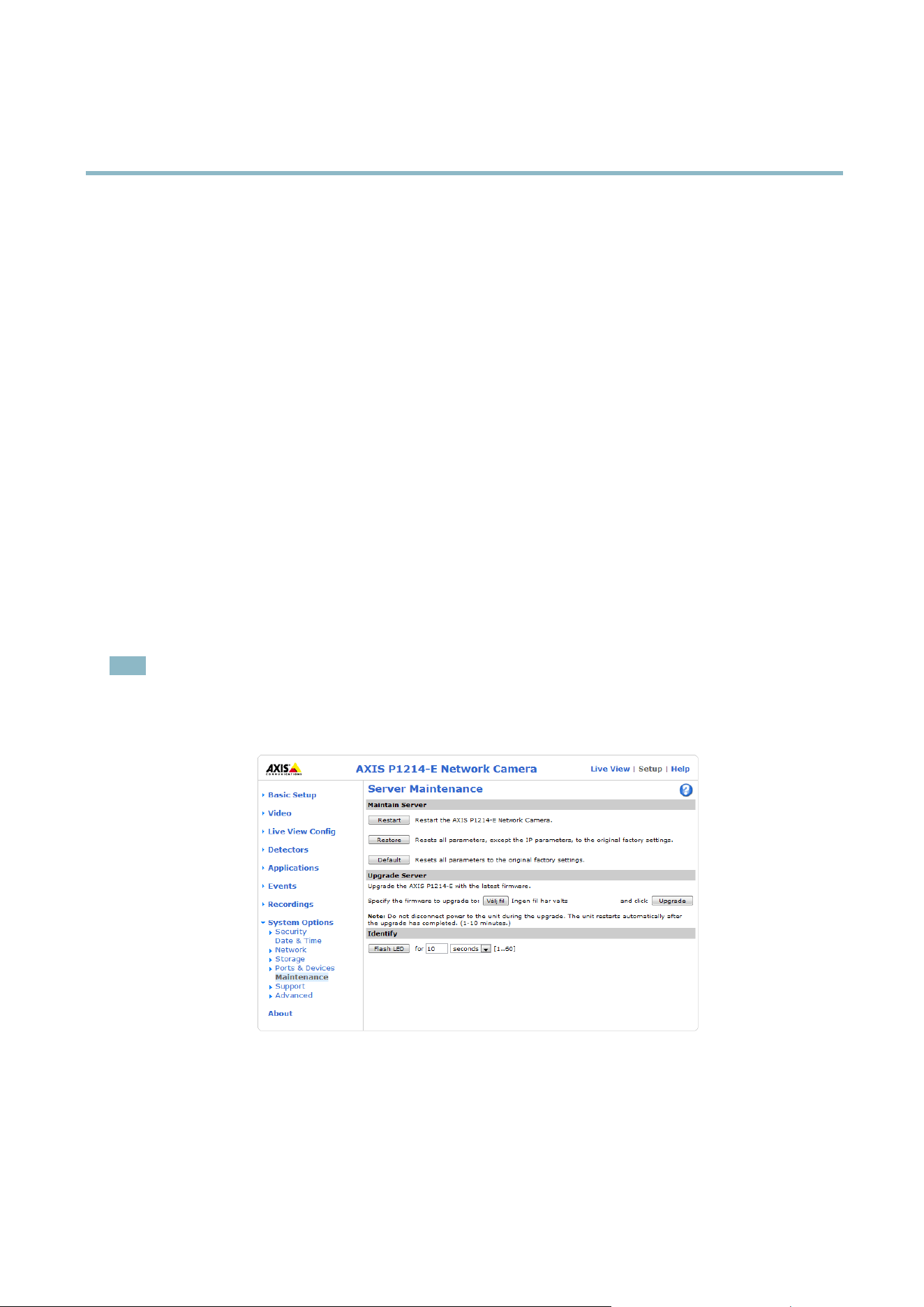
AXIS P1214–E Network Camera
Troubleshooting
Troubleshooting
Checking the Firmware
Firmware is software that determines the functionality of network devices. One of your first actions when tro u bleshooting a problem
should be to check the current firmware version. The latest version may contain a correction that fixes your particular problem. The
current firmware version in the Axis product is displayed in the page Setup > Basic Setup and in Setup > About.
Upgrading the Firmware
When you upgrade the product with the latest firmware from Axis website, the product recei ves the latest functionality available.
Always read the upgrade instructions and release notes available with each new release, before upgrading the firmware.
To upgrade, follow these instructions:
1. Save the firmware file to your computer. The latest version of the firmware is available free of charge from A xis website
at www.axis.com/techsup
2. Go to Setup > System Options > Maintenance in the pro ducts web pages.
3. Under Upgrade Server, click Browse and locate the file on your computer. Click Upgrade.
After starting the upgrade process, always wait at least 5–10 minutes before restarting the product, even if you suspect the
upgrade has failed.
AXIS Camera Management can be used for multiple upgrades. See www.axis.com for more information.
Note
• Your dealer reserves the right to charge for any repair attributable to faulty upgrade by the user.
•Preconfigured and customized settings are saved when the firmware is upgraded
(providing the features are available in
the new firmware) although this is not guaranteed by Axis Communications AB.
Emergency Recovery Procedure
If power or network connection is lost during the upgrade, the process fails and the product becomes unresponsive. Flashing r ed Status
indicator indicates a failed upgrade. To recover the product, follow the steps below. The serial number is found on the product’s label.
1. In UNIX/Linux, type the following from the command line:
41

AXIS P1214–E Network Camera
Troubleshooting
arp -s <IP address> <serial number> temp
ping -s 408 <IP address>
In Windows, type the following from a command/DOS prompt (this may require that you run the command prompt as
an administrator):
arp -s <IP address> <serial number>
ping -l 408 -t <IP address>
2. If the product does not reply in 30 seconds, restart it and wait for a reply. Press CTRL+C to stop Ping.
3. Open a browser and type in the product’s IP address. In the page that appears, use the Browse button to select the upgrade
file to use. Then cl ick Load to restart the upgrade process.
4. After the upgrade is complete (1–10 minutes), the product automatically restarts and shows a steady green on the Status
indicator.
5. Reinstall the product, referring to the Installation Guide.
If the emergency recovery procedure does not get the product up and running again, contact Axis support at www.axis.com/techsup/
Symptoms, Possible Causes and Remedial Actions
Problems setting the IP address
When using ARP/Ping
Try the installation again. The IP address must be set within two minutes after power has been
applied to the product. Ensure the Ping length is set to 408. For instructions, see Assign IP Address
using ARP/Ping on page 32.
The product is located on a
different s u bnet
If the IP address intended for the product and the IP address of the computer used to access the
product are located on different subnets, you will not be able to set the IP address. Contact your
network administrator to obtain an IP add ress.
The IP address is being used
by another device
Disconnect the Axis product from the network. Run the Ping command (in a Command/DOS
window, type ping and the IP address of the product:
•Ifyoureceive:Reply from <IP address>: bytes=32; time=10...
this means that the IP address may already be in use by another device on the netwo rk.
Obtain a new IP address from the network administrator and reinstall the product.
•Ifyoureceive:Request timed out, this means that the IP address is available for
use with the Axis product. Check all cabling and reinstall the product.
Possible IP address c onflict
with another device on the
same subnet.
The static IP address in the Axis product is used before the DHCP server sets a dynamic ad dress.
This means that if the sam e default static IP addressisalsousedbyanotherdevice,theremay
be problems accessing the product.
The product cannot be accessed from a browser
Cannot log in
When HTTPS is enabled, ensure that the correct protocol (HTTP or HTTPS) is used when attempting
to log in. You m
ay need to manually type http or https in the browser’s address field.
If the pas
sword for root is lost, the product m ust be r eset to the factory default settings. See
Reset to Factory Default Settings on page 40.
42

AXIS P1214–E Network Camera
Troubleshooting
The IP address has been
changed by DHCP
IP addresses obtained from a DHCP server are dynamic and may change. If the IP addr ess has been
changed, use AXIS IP Utility or AXIS Camera Management to located the product on the network.
Identify the product using its model or serial number.
If required, a static IP address can be assigned manually. For instructions, see the Installation and
Management Software CD or the document Assign an IP Address and Access the Video Stream on
Axis Support web at www.axis.com/techsup
Certificate error when using
IEEE 802.1X
For authentication to work properly, the date and time settings in the A xis product should be
synchronized with an NTP server. See Date & Time on page 31.
The product is accessible locally but not externally
Router configuration To configure your router to allow incoming data traffic to the A xis product, enable the NAT-traversal
feature which w ill attempt to automatically configure the router t o allow access to the Axis
product, see NAT traversal (port mapping) for IPv4 on page 35. The router must support UPnP
TM
.
Firewall protection
Check the Internet firewall with your network administrator.
Default routers required
Check if you need to configure the router settings.
Problems with the H.264 format
No H.264 displayed in the
client
Check that the relevant H.264 connection methods and correct interface are enabled in the AMC
Control Panel (streaming tab). See AX IS Media Control (AMC) on page 11.
In the AMC Control Panel, s elect the H.264 tab and click Set to default H.264 decoder.
Check that RTSP is enabled under System Options > Network > TCP/IP > A dvanced.
No multicast H.264
displayed in the client
Check with your network administrator that the multicast addresses used by the Axis product
arevalidforyournetwork.
Check with your network administrator to see if there is a firewall preventing viewing.
Multicast H.264 only
accessible by local clients
Check if your router supports multicasting, or if the router set
tings between the client and the
product need to be configured. The TTL (Time To Live) value may need to be increased.
Poor rendering of H.264
images
Color depth set incorrectly on clients. Set to 16–bit or 32–bit color.
If text overlays are blurred, or if there are other rendering problems, you may need to enable
Advanced Video Rendering from
the Video tab in the AMC Control Panel.
Ensure that your graphic
s card is us ing the latest driver. The latest drivers can usually be
downloaded fro m the manufacturer’s website.
Color saturation is different
in H.264 and Mo
tion JPEG
Modify the settings for your graphics adap ter. Refer to the adapter’s documentation for more
information.
Lower frame ra te than
expected
Reduce the number of a pplications running on the c lient computer.
Limit the number of simultaneous viewers.
Check with the network administrator that there is enough bandwidth available.
Check in the AMC Control Panel (H.264 tag) that video processing is NOT set to Decode only
key frames.
Lower the image resolution.
43

AXIS P1214–E Network Camera
Troubleshooting
Why do I not get maximum
frames per second?
See Performance Considerations on page 48.
The maximum frames per se cond is dependent on the utility fr equency (60/50 Hz) of the Axis
product. See Technical Specifications on page 46.
Image degeneration
Decrease the GOV length. Go to Video > Video Stream and select the H.264 tab to modify the
GOV length.
Status and Network indicator LEDs are flashing red rapidly
Hardware failure
Contact your Axis reseller.
Status indicator LED is flashing red and the product is inaccessible
A firmware upgrade has
been interrupted or the
firmware has otherwise been
damaged
See Emergency Recovery Procedure on page 41.
No images displayed on web page
Problems with AXIS Media
Control (Internet Explorer
only)
To enable the updating of video images in Internet Explorer, set the browser to allow ActiveX
controls. Also, make sure that AXIS Me dia Control is installed on your computer.
Installation of additional
ActiveX component
restricted or prohibited
Configure the Axis product to use a Java applet for updating video images in Internet Explorer. Go
to Setup > Live View Config and select Java applet under Default viewer.
Poor quality snapshot images
Screen incorrectly
configured on y our computer
Configure your screen to show at least 65000 colors, that is, at least 16 bits. Using only 16 or 256
colors will produce dithering artifacts in the image.
Overlay image is not displayed
Incorrect size or location of
overlay image
The overlay image may have been positioned incorrectly or ma y be too large. See Overlay Image
Settings in the online help for more informa tion.
Privacy mask is not displayed
Incorrect size or location of
privacy mask
The privacy mask may have been positioned incorrectly or may be too large.
Browser freezes
Firefox can sometimes
freeze on a slow computer
Lower the image resolution
Problems uploading files
Limited space There is only limited space available for the upload of your own files. Delete existing files to free
up space.
Motion Detection triggers unexpectedly
Changes in luminance
Motion detection is based on changes in luminance in the image. This means that if there are
sudden changes in the lighting, motion dete ction may trigg er mistakenly. Lower the sensitivity
setting to avoid probl
ems w ith luminance.
44

AXIS P1214–E Network Camera
Troubleshooting
Storage and disk management problems
Video cannot be recorded
Check that the SD card is not write protected (that is, read only).
SD card cannot be mounted Reformat the SD card and then click Mo unt.
Focus, zoom, and fan
Remote focus and zoom do
not work
In subzero temperatures, function in these hardware parts is suspended until the camera is heated
to approximately 0 °C (32 °F)
Fan cannot be activated In subzero temperatures, function in this hardware part is suspended until the camera is h e ate d to
approximately 0 °C (32 °F)
45

AXIS P1214–E Network Camera
Technical Specifications
Technical Specifications
Function/group
Item
Specifications
Model
AXIS P1214-E
Image sensor
Progressive scan RGB CMOS 1/4”
Lens f=2.8 mm, F2.0, fixed iris, fixed focus
Horizontal angle o f view: 81°
Vertical angle of view: 44°
Diagonal angle o f view: 87°
Light sensitivity 1.0 lux – 100000 lux, F2.0
Camera
Shutter time
1/24500 s to 1/6 s
Video
compression
H.264 (MPEG-4 Part 10/AVC, Baseline profile)
Motion JPEG
Resolutions
1280x720 to 320x180
Frame rate H.264
Up to 25/30 fps (50/60 Hz) in all resolutions
Frame rate
Motion JPEG
Up to 25/30 fps (50/60 Hz) in all resolutions
Video streaming
Multiple, individually configurable streams in H.264 and M otion JPEG
Controllable frame rate and bandwidth
VBR/CBR H.264
Video
Image settings
Compression, color, brightness, sharpness, contrast, white balance,
exposure value,
exposure control, exposure zones, backlight compensation, fine tuning of behavior at
low light
Rotation: 0°, 90°, 180°, 270°
Mirroring of im age s
Text and image overlay
Privacy mask
AXIS Corridor Format
Security Password protection, IP address filtering, HTTP S encryption*, IEEE 802.1X network access
control*, digest authenticati
on, user a ccess log
*This product includes softw are developed by the Open SSL Project for use in the Open
SSL Toolkit (www.openssl.org)
Network
Supported
protocols
IPv4/v6, HTTP, H TTPS*
, SSL/TLS*, QoS Layer 3 DiffServ, FTP, CIFS/SMB, SMTP, Bonjour,
UPnP,SNMPv1/v2c/v3(MIB-II),DNS,DynDNS,NTP,RTSP,RTP,TCP,UDP,IGMP,RTCP,
ICMP, DHCP, ARP, SOCKS
*This product
includes software developed by the Open SSL Project for use in the Open
SSL Toolkit (www.openssl.org)
Application
Programming
Interface
Open API for so ftw are integration, including VAPIX® and AXIS Camera Application
Plat
form from Axis Communications; specifications available at www.axis.com
Includes the ONVIF specification available at www.onvif.org
Support for AXIS Video Hosting System (AVHS) with One-Click Camera Connection
Intelligent video
Video motion detection, active tampering alarm, Support for AXIS Camera Application
Platform ena bling installation of additional applications
Triggers
Intelligent video, digital I/O, manual trigger, network lost, s torage status, syste m
initializing
Actions File upload via FTP, HTTP and email
Notification via email, HTTP and TCP
Video recording to edg e storage
Pre- and post-alarm video buffering
System
Inte
gration
46

AXIS P1214–E Network Camera
Technical Specifications
Function/group
Item
Specifications
External output activatio n
Status LED
Video access from
web b rowser
Camera live view
Video recording to file (ASF)
Customizable HTML pages
Windows 7, Windows Vista, Windows XP, Windows Server 2008, Windows Server 2003
DirectX 9c or higher
For other operating systems and browsers, see www.axis.com/techsup
Management and
maintenance
AXIS Camera Management tool on CD and web-based configuration
Firmware upgrades over HTTP or FTP, firmware available on www.axis.com
Installation aids Pixel counter
Casing
Main unit: polycarbonate c asing
Sensor unit: IP66 Nema 4X-rated metal casing (aluminum)
Memory 256 MB RAM , 128 MB Flash
Power
8-28 V DC max 4.7 W
Power over Ethernet (PoE) IEEE 802.3af Class 2, max. 6.4 W
Connectors
RJ-45 for 10BASE-T/100BASE-TX PoE
RJ-12 for sensor unit
Terminal blocks for power, 1 alarm input and 1 output
Edge storage
Micro SD/SDHC memory card slot (card not included)
Support for recording to network share (Network Attached Storage or file server).
Operating
conditions
Temperature: –20 ºC to 50 ºC (–4 ºF to 122 ºF)
Humidity 10–85% RH (non-condensing)
Approvals
EN 55022 Class B, EN 61000-3-2, EN 61000-3-3, EN 61000-6-1, EN 55024, FCC Part 15
Subpart B Class B, ICES-003 Class B, VCCI Class B, C-tick AS/NZS
CISPR 22, KCC Class B,
EN/IEC 60950-1, IEC 60068-2-6 (Vibration) class 4M4, IEC 60068-2-27 (shock) Class
4M3, IEC 60068-2-1. IEC 60068-2-2, 60068-2-78 Class 3K3
P1214-E Sensor unit: EN/IEC 60950-22, IEC 60529 IP66,
NEMA 250 Type 4X, IEC
60068-2-78 Class 4K3, IEC 60068-2-14, IEC 60068-2-30
Dimensions
(HxWxD)
Main unit: 31 x 76 x 103 mm (1.1” x 3.0” x 4.1”)
Sensor unit: diameter 20 mm (0.8”), depth 53 mm (2.1”)
Weight
Main unit: 109 g (0.24 lb.)
Sensor unit: 248 g (0.55 lb.)
General
Included
accessories
Mounting kit, I
nstallation Guide, Axis Warranty Document, AVHS Authentication key,
Installation and Management S oftware CD, Windows decoder 1-user license
Video
management
software (sold
separately)
AXISCameraStation—Videomanagementsoftwareforviewingandrecordingupto50
cam
eras
See www.axis.com/products/video/software/ for more software applications via partners
Optional
accessories
AXIS T8412 Installation Display
Axis PoE Midspans
AXIS Camera Station and video management software from Axis’ Application
Development Partners
For more software information, see www.axis.com/products/video/software/
47

AXIS P1214–E Network Camera
Technical Specifications
Performance Considerations
When settings up your s ystem, it is important to consider how various settings and situations will affect performance. Some factors
affect the amount of bandwidth (the bit rate) required , others can affect the frame rate, and some affect both. If the load on the
CPU reache s its maximum, this will also affect the frame rate.
The following factors are among the most important to consider:
• High image resolution and/or lower c ompression levels result in images containing more data. Bandwidth affected.
• Access by large numbers of Motion JPEG and/or unicast H.264 clients. Bandwidth affected.
• Simultaneous viewing of different streams (resolution, c ompression) by different clients. Effect on fram e rate and bandwidth.
• Accessing Motion JPEG and H.264 video streams simultaneously. F rame rate and bandwidth affected.
• Heavy usage of event settings affect the product’s CPU l oad. Frame rate affected.
• Heavy network utilization due to poor infrastructure. Ba ndwidth affected.
• Viewing on poorly performing client computers lowers perceived performance. Frame rate affected.
48

User Manual Ver. M2.2
AXIS P1214–
E Network Camera Date: August 2012
© Axis Communications AB, 2012
Part No. 47
875