Loading ...
Loading ...

www.Lanzar.com
3
FUNCTIONS
THE OUTSIDE
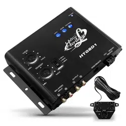
1. Inputs: The inputs of The HTGBD1 use a balanced input circuit to help minimize
induced noise. They are also designed to handle very high signal voltages up
to 15 volts.
2. Outputs: These RCA connectors should be connected to the next component
after the HTGBD1, such as a crossover, equalizer, or amplier. Just remember,
the HTGBD1 should go inline before a crossover.
3. Dash Remote Control
4. Power Connector
5. Para-Bass Controls: These 2 knobs control the Para-Bass functions of the
HTGBD1. The SWEEP knob allows you to pick the center frequency that you
want the HTGBD1 bass restoration circuit to maximize. The WIDE knob abjusts
how wide of a frequency range the HTGBD1 will eect.
6. The PFM Subsonic Filter Switch: The HTGBD1 utilizers a PFM Subsonic Filter
Switch which will help with speaker control and amplier power management.
This PFM Subsonic Filter Switch comes with three frequencies selections 35Hz /
50Hz / 80Hz. On most systems, setting the switch at 33Hz is ne. If you want to
protect your speaker system even more, you should try a higher frequency.
Often a higher frequency actually sounds louder and cleaner.
7. Bass Maximize Indicator: These three LED indicators ashes when the bass
maximization circuit is activated.
8. Power On LED
Loading ...
Loading ...
Loading ...