
Sarix Corner Camera 3 Series Installation Manual
C6714M | 02/22
2
Legal Notices
©2022,PelcoCorporation.Allrightsreserved.PELCO,thePELCOlogo,PELCOaretrademarksof
PelcoCorporation.Othernamesorlogosmentionedhereinmaybethetrademarksoftheirrespective
owners.Theabsenceofthesymbols™and®inproximitytoeachtrademarkinthisdocumentoratallis
notadisclaimerofownershipoftherelatedtrademark.PelcoCorporationprotectsitsinnovationswith
patentsissuedintheUnitedStatesofAmericaandotherjurisdictionsworldwide(seewww.pelco.com).
Unlessstatedexplicitlyandinwriting,nolicenseisgrantedwithrespecttoanycopyright,industrial
design,trademark,patentorotherintellectualpropertyrightsofPelcoCorporationoritslicensors.
Disclaimer
Thisdocumenthasbeencompiledandpublishedusingproductdescriptionsandspecificationsavailable
atthetimeofpublication.Thecontentsofthisdocumentandthespecificationsoftheproductsdiscussed
hereinaresubjecttochangewithoutnotice.PelcoCorporationreservestherighttomakeanysuch
changeswithoutnotice.NeitherPelcoCorporationnoranyofitsaffiliatedcompanies:(1)guaranteesthe
completenessoraccuracyoftheinformationcontainedinthisdocument;or(2)isresponsibleforyour
useof,orrelianceon,theinformation.PelcoCorporationshallnotberesponsibleforanylossesor
damages(includingconsequentialdamages)causedbyrelianceontheinformationpresentedherein.
PelcoCorporation
www.pelco.com
C6714M
Revision:2-EN
20220308

Sarix Corner Camera 3 Series Installation Manual
C6714M | 02/22
3
Table of Contents
LegalNotices 2
Disclaimer 2
ImportantSafetyInformation 5
RegulatoryNotices 5
DisposalandRecyclingInformation 6
Overview 1
AssembledView 1
HousingFrontView 2
GimbalBottomView 3
GimbalFrontView 4
HousingRearView 5
Cover-RearView 6
ConduitBoxAccessoryView 7
Installation 8
Pre-DeploymentIn-BoxConfiguration 8
RequiredToolsandMaterials 8
CameraPackageContents 8
InstallationSteps 9
RemovingtheFrontCoverandGimbal 9
PreparingtheMountingGrommets 11
MountingandAimingVideoAnalyticsCameras 12
InsertingCablesthroughtheSealingGrommet 12
MountingtheCornerCameraBase 13
ConnectingCables 18
MountingtheCameraGimbaltotheBase 18
InstallingtheFrontCover 19
InitializingaCameraUsernameandPassword 20
AssigninganIPAddress 21
AccessingtheLiveVideoStream 21
(Optional)ConfiguringmicroSDCardStorage 21
FocusingtheCamera 21
ConfiguringtheCamera 22
InstallationwiththeConduitBoxAccessory 23
MountingtheConduitGangBox 23
MountingtheCameraBasetotheConduitBox 25
MountingtheCameraGimbal 30
InstallingtheFrontCover 31
CableConnections 32

Sarix Corner Camera 3 Series Installation Manual
C6714M | 02/22
4
ConnectingExternalPower 32
ConnectingtoExternalDevices 33
ConnectionStatusLEDIndicator 34
TroubleshootingNetworkConnectionsandLEDBehavior 34
ResettingtoFactoryDefaultSettings 35
SettingtheIPAddressUsingtheARP/PingMethod 35
Cleaning 35
DomeBubble 35
Body 36
ForMoreInformation 36
PelcoTroubleshootingContactInformation 36
Sarix Corner Camera 3 Series Installation Manual
C6714M | 02/22
5
Important Safety Information
Thismanualprovidesinstallationandoperationinformationandprecautionsfortheuseofthisdevice.
Incorrectinstallationcouldcauseanunexpectedfault.Beforeinstallingthisequipmentreadthismanual
carefully.Pleaseprovidethismanualtotheowneroftheequipmentforfuturereference.
ThisWarningsymbolindicatesthepresenceofdangerousvoltagewithinandoutsidethe
productenclosurethatmayresultinariskofelectricshock,seriousinjuryordeathto
personsifproperprecautionsarenotfollowed.
ThisCautionsymbolalertstheusertothepresenceofhazardsthatmaycauseminorormoderate
injurytopersons,damagetopropertyordamagetotheproductitselfifproperprecautionsarenot
followed.
Failuretoobservethefollowinginstructionsmayresultinsevereinjuryordeath.
l
Installationmustbeperformedbyqualifiedpersonnelonly,andmustconformtoalllocalcodes.
l
Donotconnectdirectlytomainspowerforanyreason.
Failuretoobservethefollowinginstructionsmayresultininjurytopersonsordamagetothe
device.
l
Donotexposethecameradirectlytohighlevelsofx-ray,laser,orUVradiation.Directexposure
maycausepermanentdamagetotheimagesensor.
l
Donotinstallnearanyheatsourcessuchasradiators,heatregisters,stoves,orothersourcesof
heat.
l
Donotsubjectthedevicecablestoexcessivestress,heavyloadsorpinching.
l
Donotopenordisassemblethedevice.Therearenouserserviceableparts.
l
Referalldeviceservicingtoqualifiedpersonnel.Servicingmayberequiredwhenthedevicehas
beendamaged(suchasfromaliquidspillorfallenobjects),hasbeenexposedtorainormoisture,
doesnotoperatenormally,orhasbeendropped.
l
Donotusestrongorabrasivedetergentswhencleaningthedevicebody.
l
UseonlyaccessoriesrecommendedbyPelco.
l
ThisdevicecomplieswithEN60529IP66andIP67ratings.
Regulatory Notices
Thisdevicecomplieswithpart15oftheFCCRules.Operationissubjecttothefollowingtwoconditions:
(1)thisdevicemaynotcauseharmfulinterference,and(2)thisdevicemustacceptanyinterference
received,includinginterferencethatmaycauseundesiredoperation.
ThisClassBdigitalapparatuscomplieswithCanadianICES-003.
ThisequipmenthasbeentestedandfoundtocomplywiththelimitsforaClassBdigitaldevice,pursuant
toPart15oftheFCCrules.Theselimitsaredesignedtoprovidereasonableprotectionagainstharmful
interferenceinaresidentialinstallation.Thisequipmentgenerates,usesandcanradiateradiofrequency
energyand,ifnotinstalledandusedinaccordancewiththeinstructions,maycauseharmfulinterference
toradiocommunications.However,thereisnoguaranteethatinterferencewillnotoccurinaparticular
installation.Ifthisequipmentdoescauseharmfulinterferencetoradioortelevisionreception,whichcan
Sarix Corner Camera 3 Series Installation Manual
C6714M | 02/22
6
bedeterminedbyturningtheequipmentoffandon,theuserisencouragedtotrytocorrectthe
interferencebyoneormoreofthefollowingmeasures:
l
Reorientorrelocatethereceivingantenna.
l
Increasetheseparationbetweentheequipmentandthereceiver.
l
Connecttheequipmentintoanoutletonacircuitdifferentfromthattowhichthereceiveris
connected.
l
Consultthedealeroranexperiencedradio/TVtechnicianforhelp.
ChangesormodificationsmadetothisequipmentnotexpresslyapprovedbyPelcoCorporationor
partiesauthorizedbyPelcoCorporationcouldvoidtheuser’sauthoritytooperatethisequipment.
Disposal and Recycling Information
Whenthisproducthasreachedtheendofitsusefullife,pleasedisposeofitaccordingtoyourlocal
environmentallawsandguidelines.
Riskoffire,explosion,andburns.Donotdisassemble,crush,heatabove100°C(212°F),orincinerate.
European Union:
Thissymbolmeansthataccordingtolocallawsandregulationsyourproductshouldbedisposedof
separatelyfromhouseholdwaste.Whenthisproductreachesitsendoflife,takeittoacollectionpoint
designatedbylocalauthorities.Somecollectionpointsacceptproductsforfree.Theseparatecollection
andrecyclingofyourproductatthetimeofdisposalwillhelpconservenaturalresourcesandensurethat
itisrecycledinamannerthatprotectshumanhealthandtheenvironment.
Sarix Corner Camera 3 Series Installation Manual
C6714M | 02/22
1
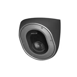
Overview
Assembled View
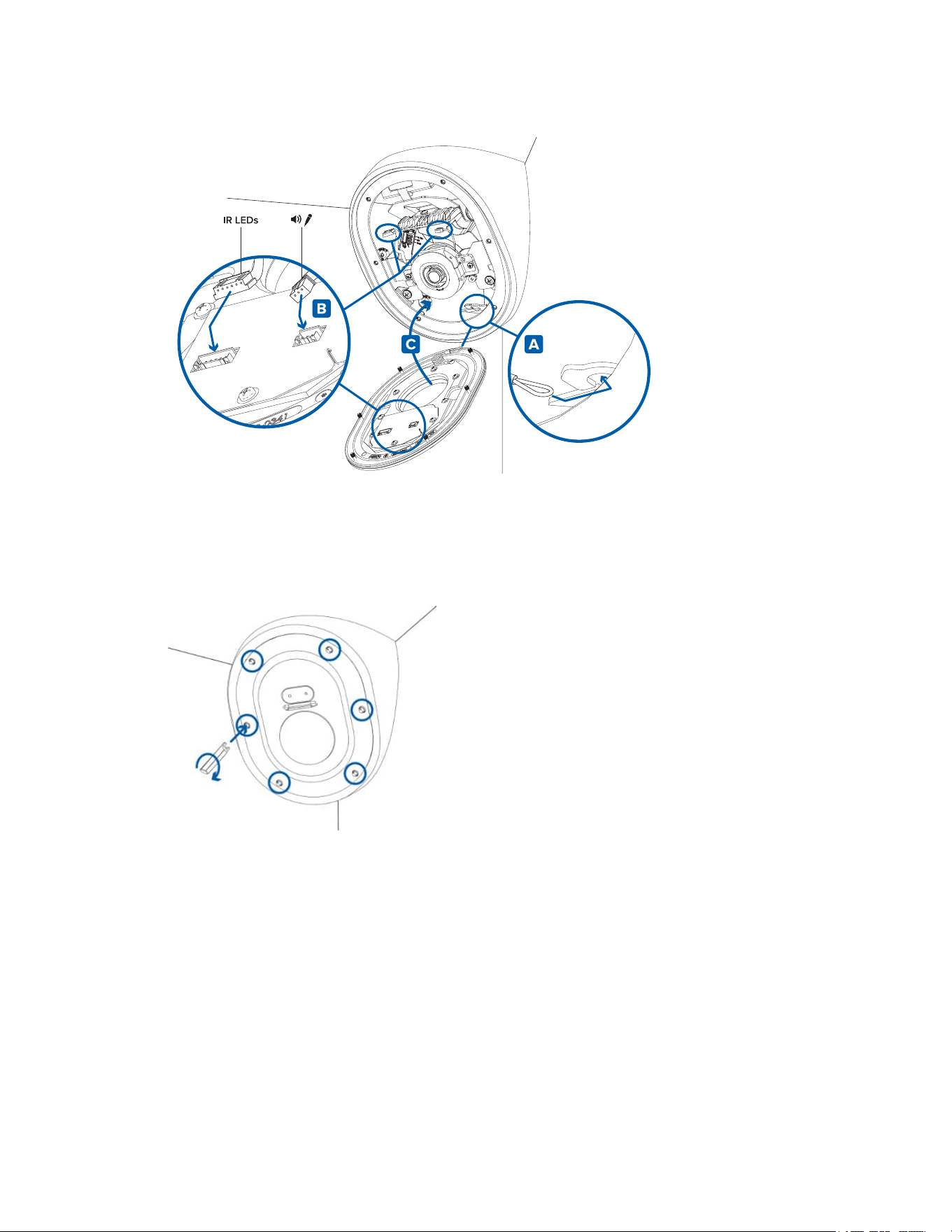
1. Front cover
Vandalresistantfrontcover.
2. Recording LED
LEDturnsonwhenthecameraisstreamingvideotoalocalmicroSDcard,ACCoranotherVMS
system,orthecamerawebinterface.
3. Microphone
Built-inaudioreceiver.
4. Tamper resistant screws
Tamperresistantcaptivescrewstofixthedomecovertothebase.
Sarix Corner Camera 3 Series Installation Manual
C6714M | 02/22
2
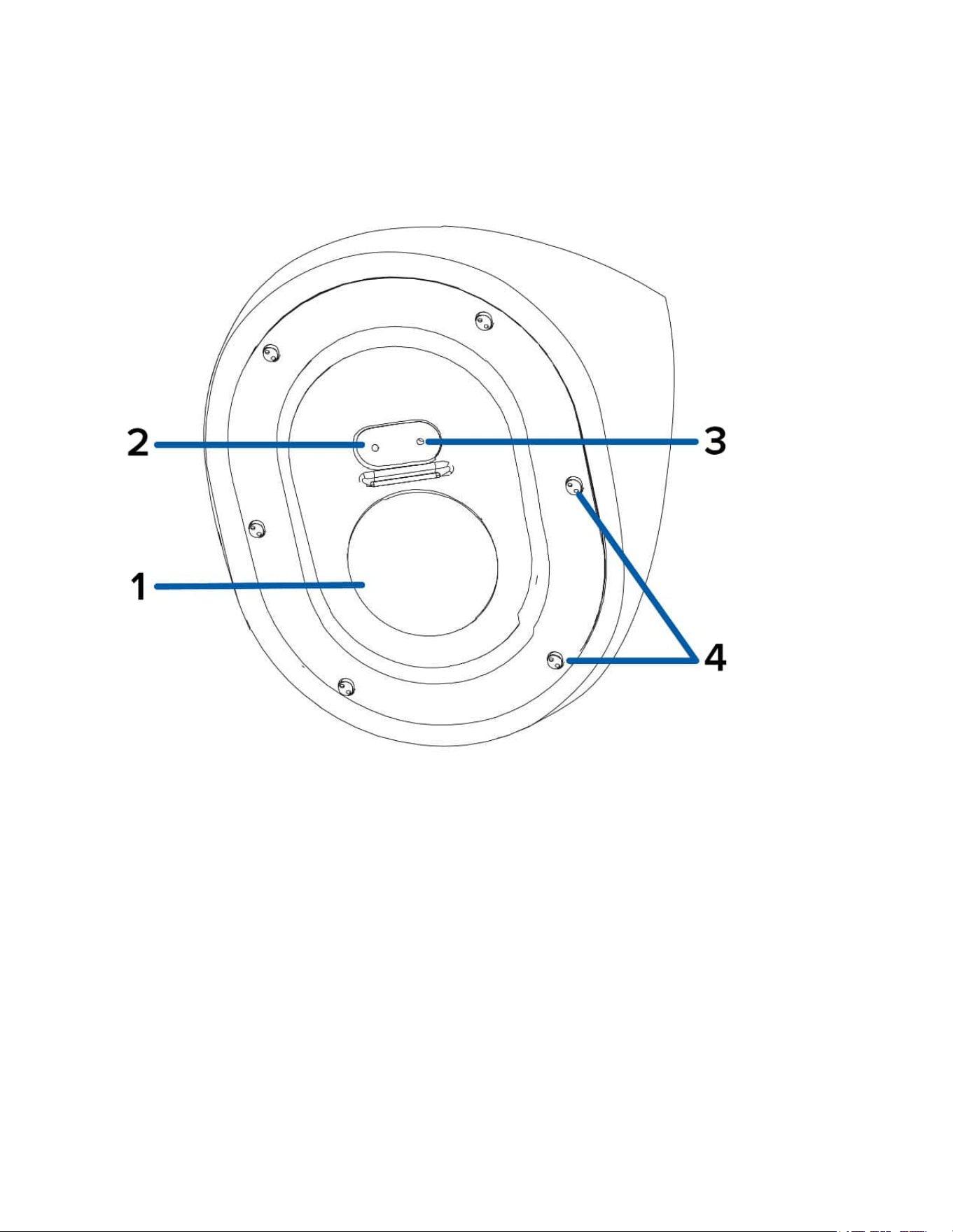
Housing Front View
1. Camera lens
Lensthatcapturesthevideoimage.
2. LED cable
ConnectthecabletotheLEDconnectoronthefrontcovertopowertheRecordingLEDandIR
LED.
3. Microphone cable
Connectthecabletothemicrophoneaudioconnectoronthefrontcovertousethebuilt-in
microphone.
4. Lanyard hook
Ahookforconnectingthelanyardonthecameracover.
Sarix Corner Camera 3 Series Installation Manual
C6714M | 02/22
3
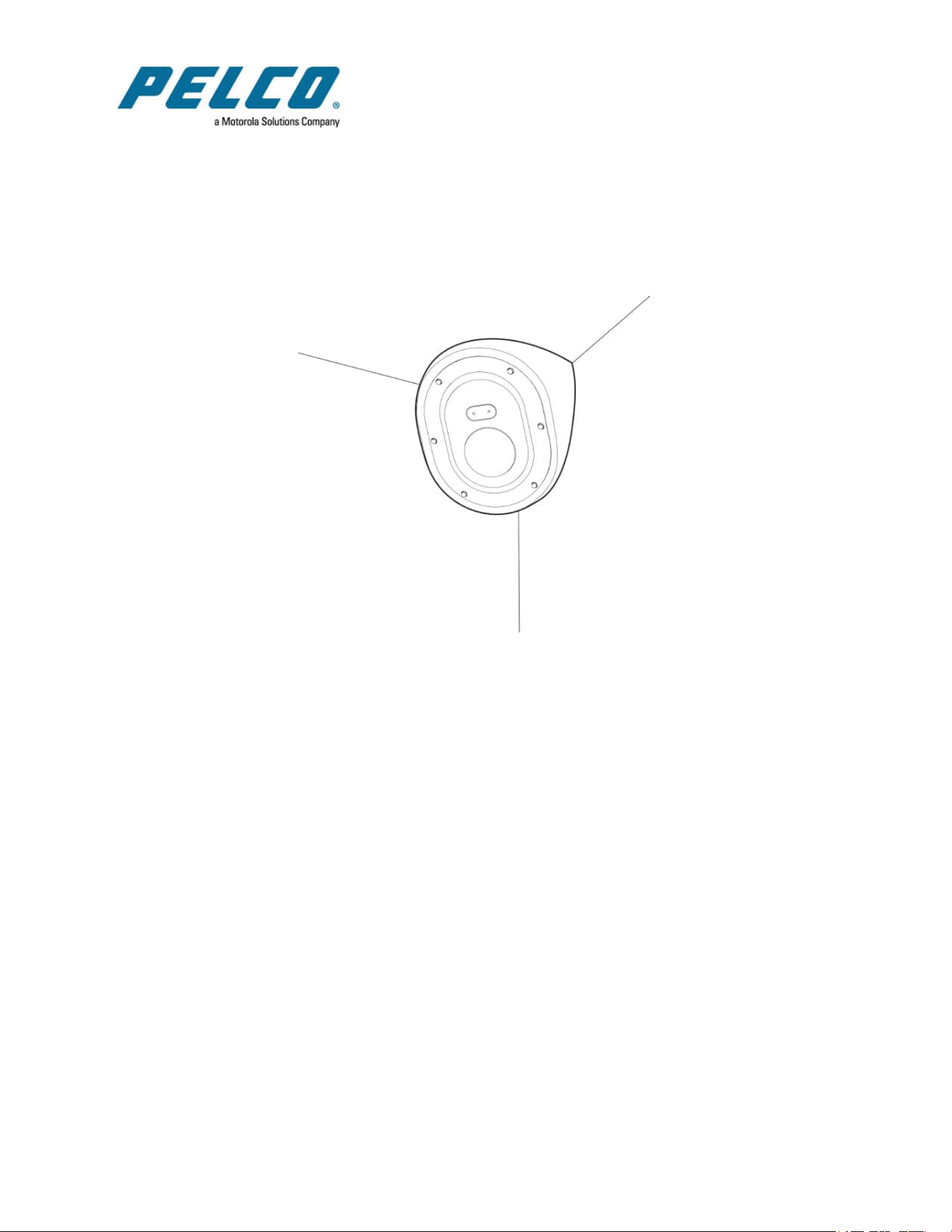
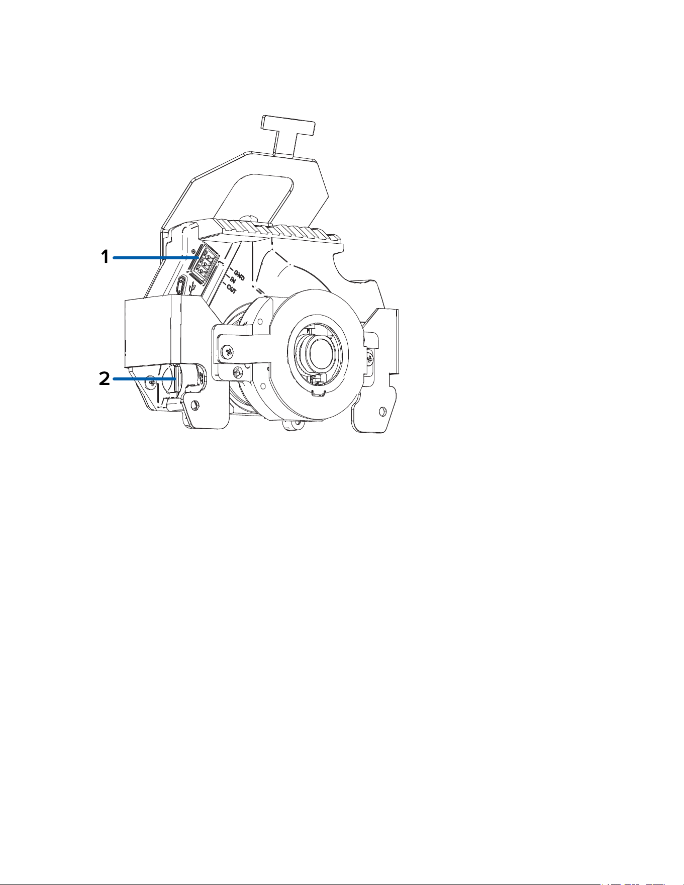
Gimbal Bottom View
1. Power connector block
AcceptsaterminalblockwitheitheranACorDCpowerconnection.DCinputcanbeeither
polarity.OnlyrequiredwhenPoweroverEthernetisnotavailable.
2. Ethernet port
AcceptsanEthernetconnectiontoanetwork.Servercommunicationandimagedata
transmissionoccursoverthisconnection.Alsoreceivespowerwhenitisconnectedtoanetwork
thatprovidesPoweroverEthernet.
3. Connection status LED indicator
GreenLEDprovidesinformationaboutdeviceoperation.Formoreinformation,seeConnection
Status LED Indicator.
4. Link LED indicator
AmberLEDindicatesifthereisanactiveconnectionintheEthernetport.
Sarix Corner Camera 3 Series Installation Manual
C6714M | 02/22
5
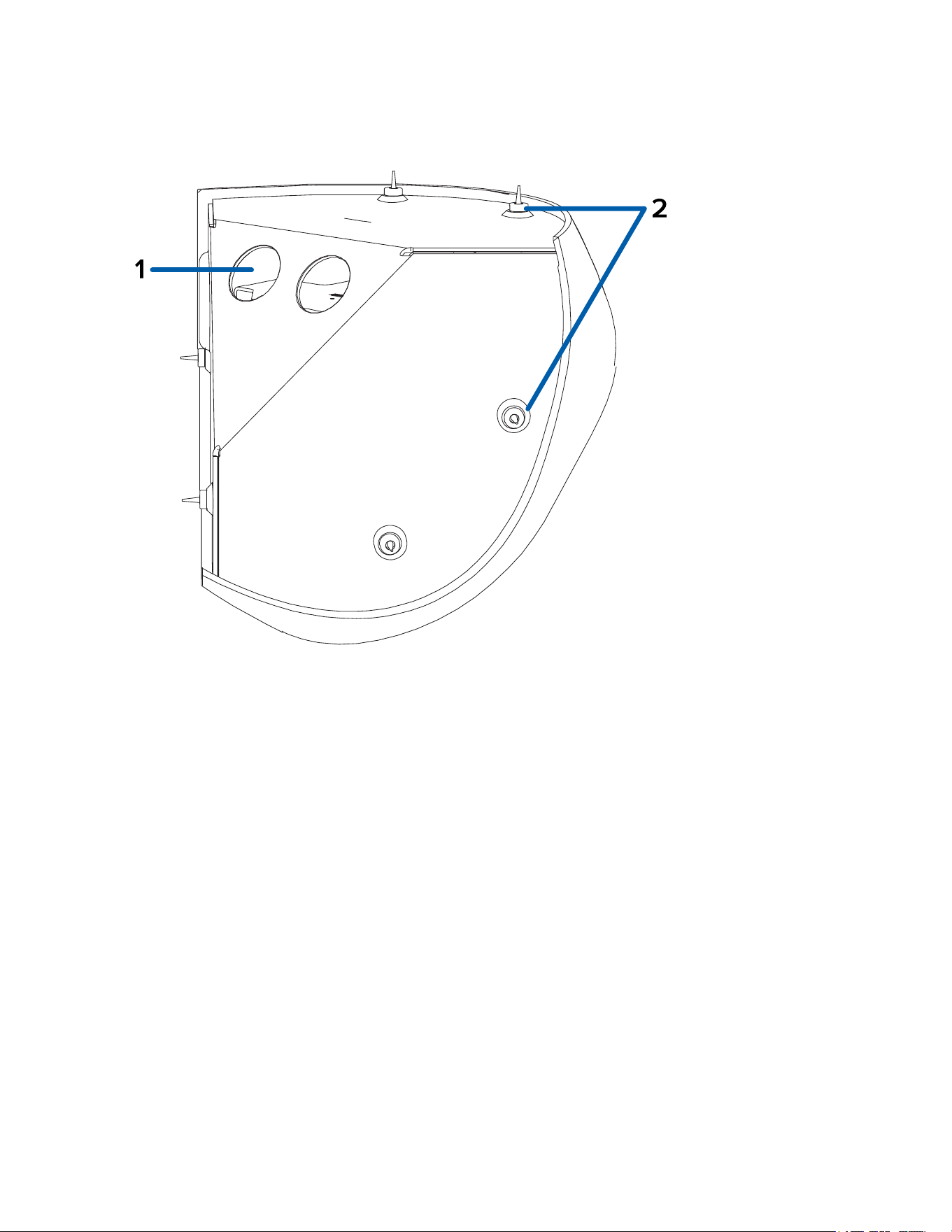
Housing Rear View
1. Cable entry holes (x2)
Entryholesforthecablesrequiredforcameraoperation.
2. Mounting holes
Mountingpointsforthecamera(x6)withrubbergrommetsinserted.
Sarix Corner Camera 3 Series Installation Manual
C6714M | 02/22
6
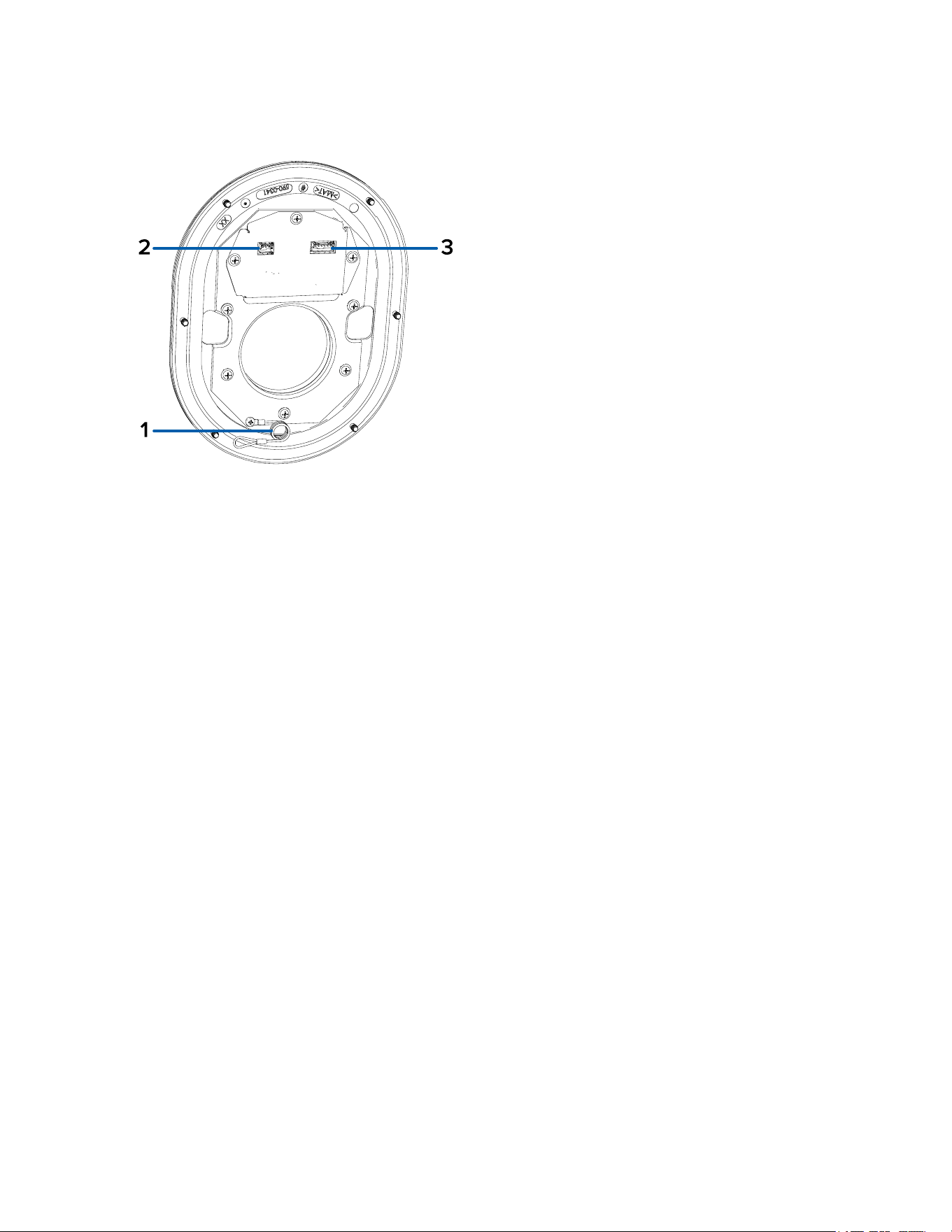
Cover - Rear View
1. Lanyard
Connectstothelanyardanchoronthecamerabase.
2. Microphone connector
Connectthemicrophoneaudiocabletousethebuilt-inmicrophone.
3. LED connector
ConnecttheLEDcabletopowerthecamera'sRecordingLEDandIRLED.
Sarix Corner Camera 3 Series Installation Manual
C6714M | 02/22
7
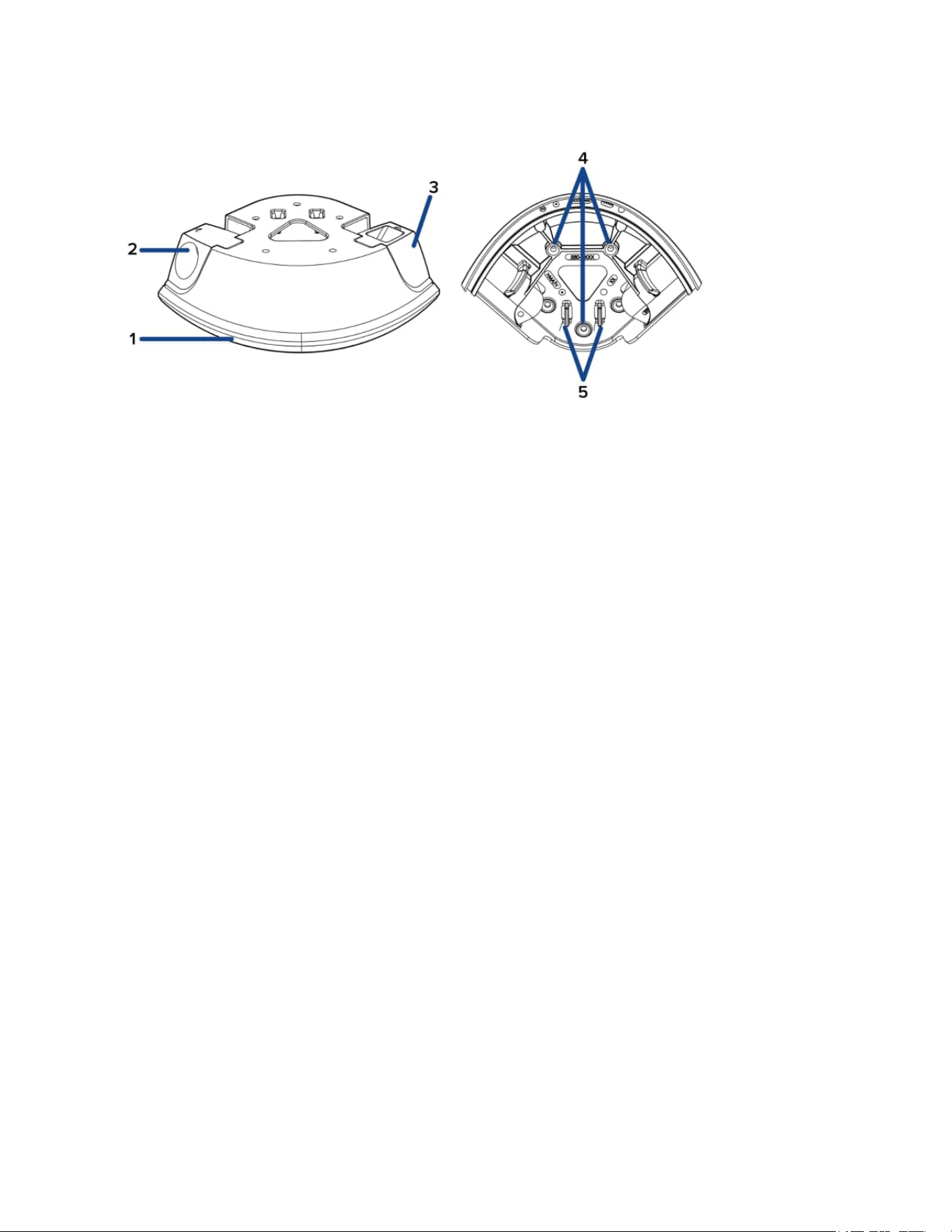
Conduit Box Accessory View
1. Rubber gasket
Rubbergasketforcreatingasealbetweenthecornercameraandconduitboxaccessory.
2. Conduit entry point
Removableconduitentrypointthatcanbeinstalledoneithersideoftheconduitbox.Theconduit
boxcomeswith2sizesofconduitentrypointstouse:3/4"NPTor1/2"NPT.
3. Closed conduit entry point
Thematchingpiecetotheconduitentrypointusedtoclosetheoppositesideoftheconduitbox.
4. Mounting holes
Mountingpointsfortheconduitbox(x3).
5. Ethernet cable clips
ClipstosecuretheEthernetcable.
Sarix Corner Camera 3 Series Installation Manual
C6714M | 02/22
8
Installation
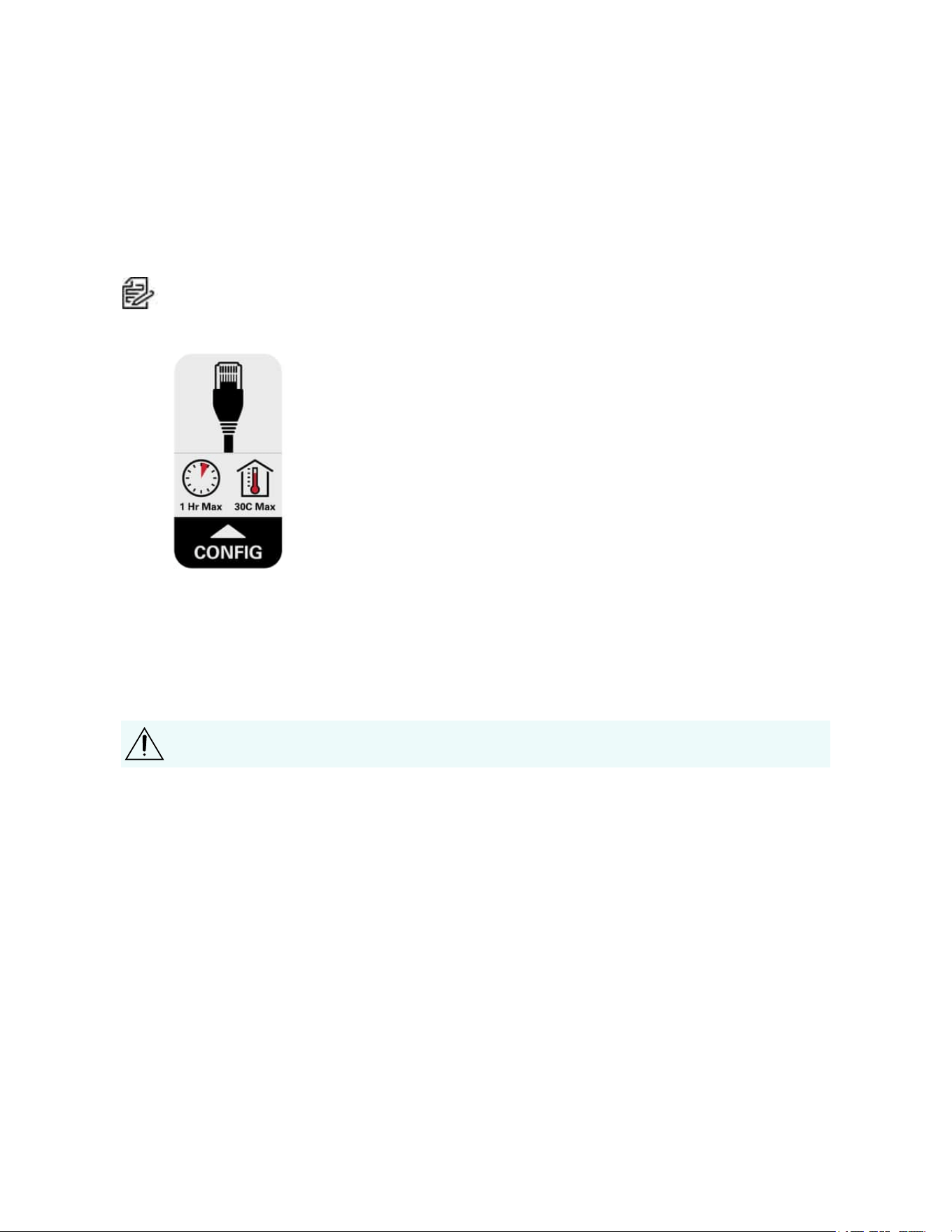
Pre-Deployment In-Box Configuration
ThecameracomesequippedwithanRJ45configurationcablepre-installedforusersthatwantto
configurecamerasettingsbeforeinstallingthecamera.TheRJ45connectorontheconfigurationcableis
accessiblethroughthesmallflaponthesideofthecameraboxforeasyconfigurationbeforeunpacking
thecamera.
Note:Themaximumrecommendeddurationofin-boxconfigurationis1hour.Themaximum
recommendedambienttemperatureis30°C(86°F).
1. Locateandopentheflaponthesideofthecamerapackaging.LookfortheConfiglabel.
2. ConnectanetworkcabletotheRJ45plugontheconfigurationcable.Thenetworkcablemust
providePoE.IEEE802.3afClass3,topowerthecameraduringconfiguration.
3. ConnecttothecamerausingtheCameraConfigurationTool,orthecamera'swebbrowser
interfacetoconfigurethecamera'ssettings.Formoreinformationaboutconnectingtothe
camera,seeAssigning an IP Address,andAccessing the Live Video Stream.
4. Onceyouhavefinishedmakingconfigurationchanges,unplugthenetworkcable.
Becarefulwhenhandlingthecameraafterconfiguringitinsidethepackaging.Thecameramay
behotwhenhandlingitorremovingfromthepackagingimmediatelyafterin-boxconfiguration.
Required Tools and Materials
l
Smallslottedscrewdriverwith5/64”or2mmbladewidth—forconnectingpowerwhennotusing
PoweroverEthernet.
l
No.2Phillipsscrewdriver—forattachingcameratoamountingsurface
l
Drillfordrillingmountingholesinthemountingsurface
l
Cuttingtoolforcuttingcableaccessholeinthemountingsurface
l
Siliconesealant
Camera Package Contents
Ensurethepackagecontainsthefollowing:
l
PelcoSarixHighSecurityCornercamera
l
RJ-45grommetpiercingcap
l
Microphoneaudiocable
Sarix Corner Camera 3 Series Installation Manual
C6714M | 02/22
9
l
2cableentrygrommets
l
6wallanchorsforsolidwalls,for#8-10screws
l
6mountingscrews,#10-1.25"long,flathead,Phillips,stainlesssteel
Installation Steps
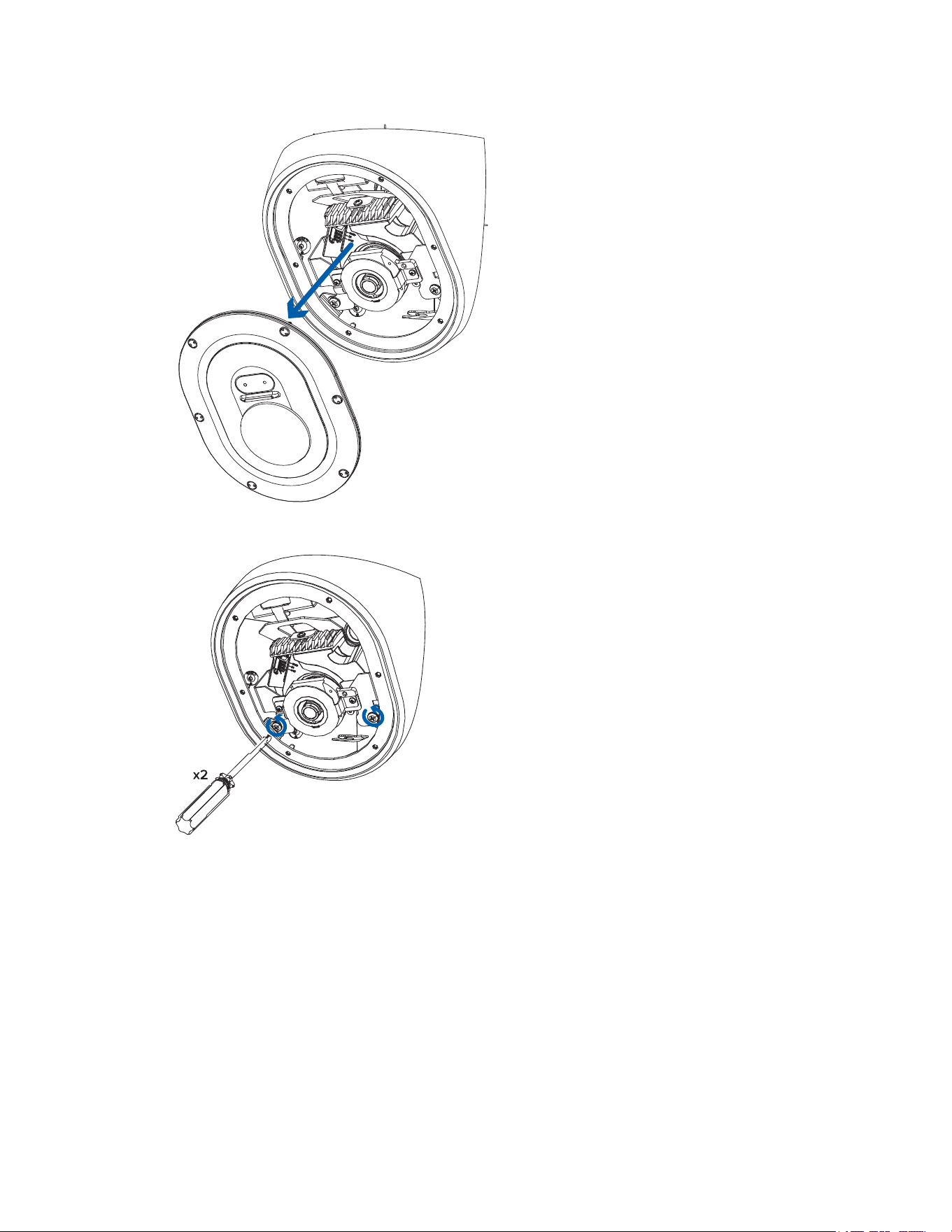
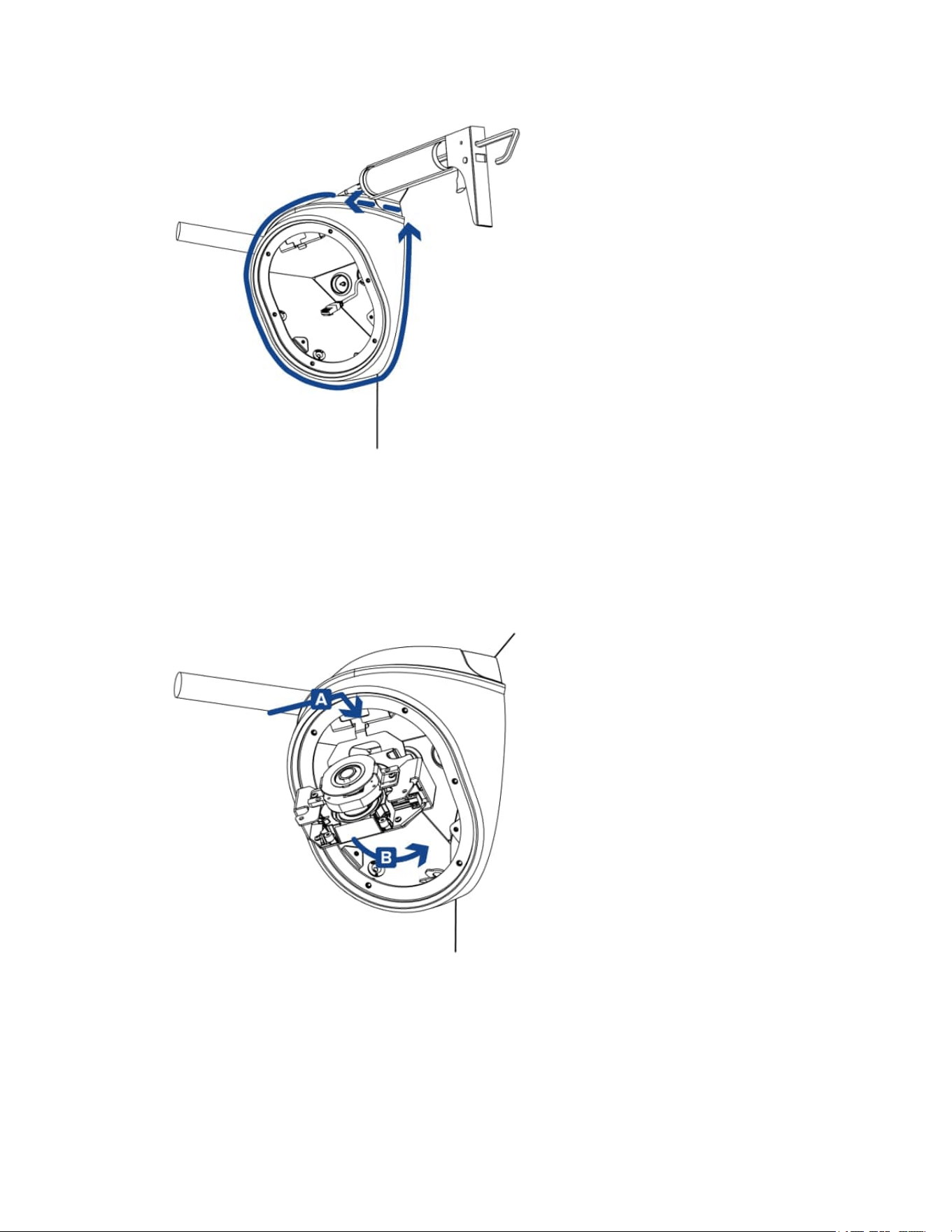
Removing the Front Cover and Gimbal
Beforemountingthecamera,youneedtoremovethefrontcoverandcameragimbalfromthehousing:
Becarefulnottoscratchortouchthedomebubble.Theresultingmarksorfingerprintsmayaffectthe
overallimagequality.Keeptheprotectivecoversontheoutsideofthedomebubbleuntiltheinstallation
iscomplete.
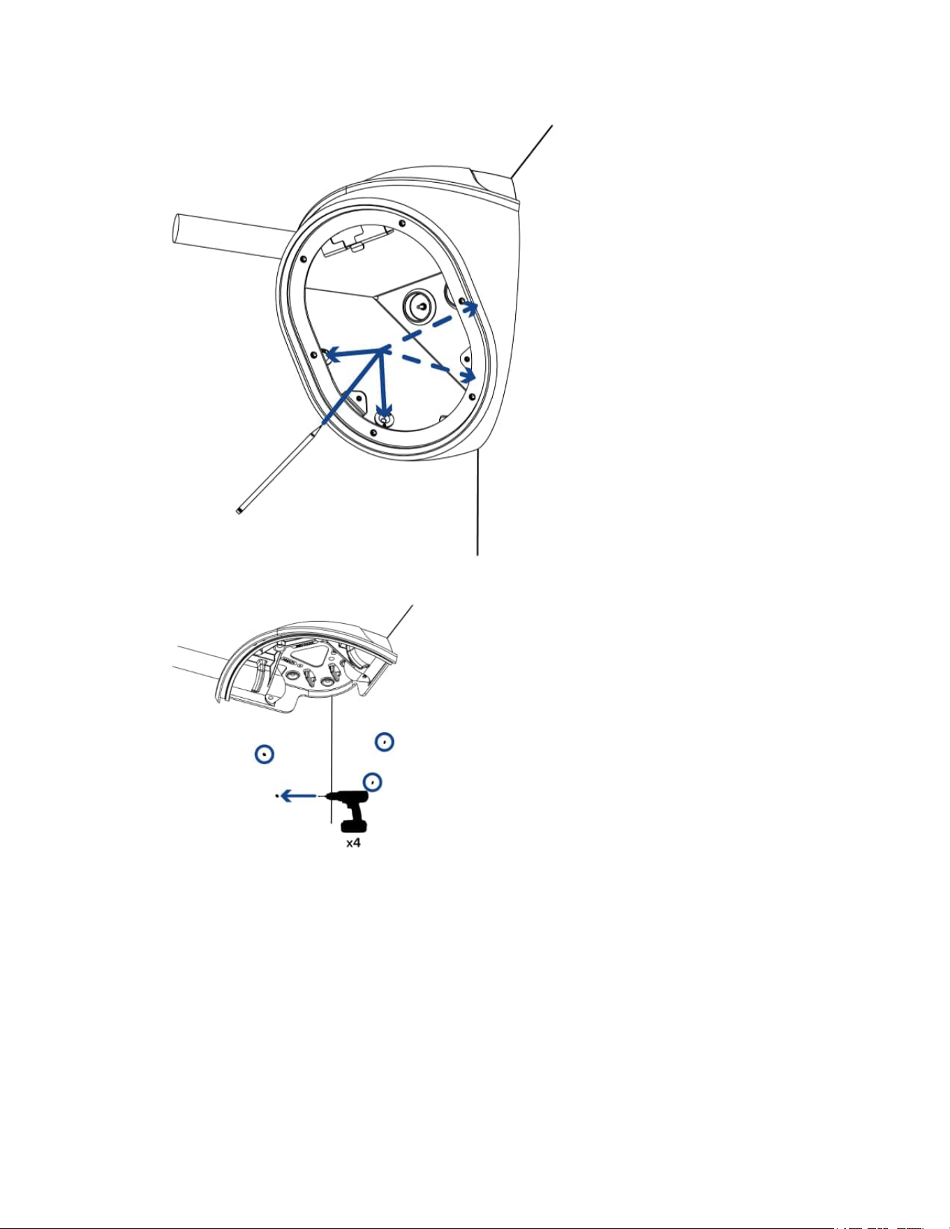
1. Loosenthescrewsthatfixthecovertothebase.Usethesupplieddrivertoloosenthescrews.
2. Pullthefrontcoveroffofthecamerabase.
Sarix Corner Camera 3 Series Installation Manual
C6714M | 02/22
10
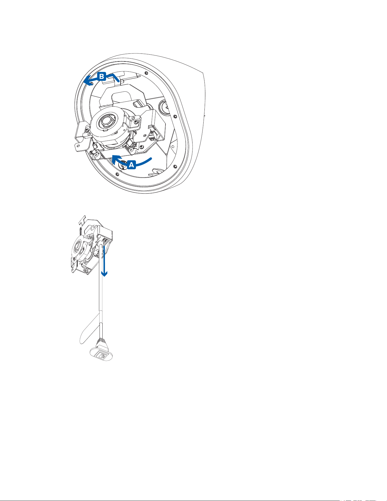
3. Loosenanddetachthetwoscrewsthatsecurethegimbaltothebase.
4. Rotatethebottompartofthegimbalupwardsafterthescrewsareremoved(A),thenunhookthe
gimbalfromtheslotatthetopofthehousingandpullthegimbalout(B).
Sarix Corner Camera 3 Series Installation Manual
C6714M | 02/22
11
5. RemovetheRJ-45in-boxconfigurationcablethatcomespre-installedonthecamera.
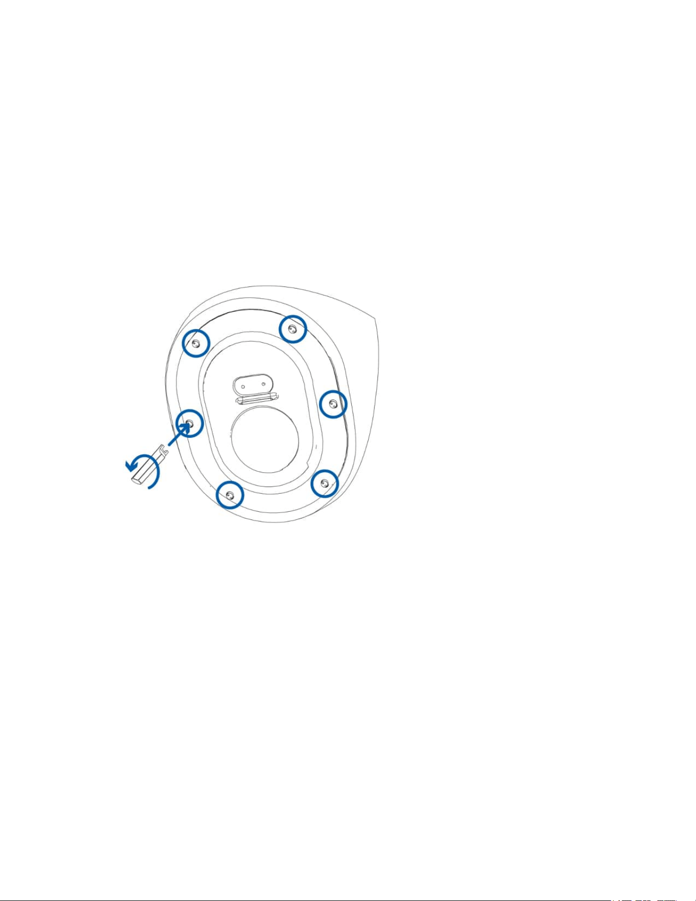
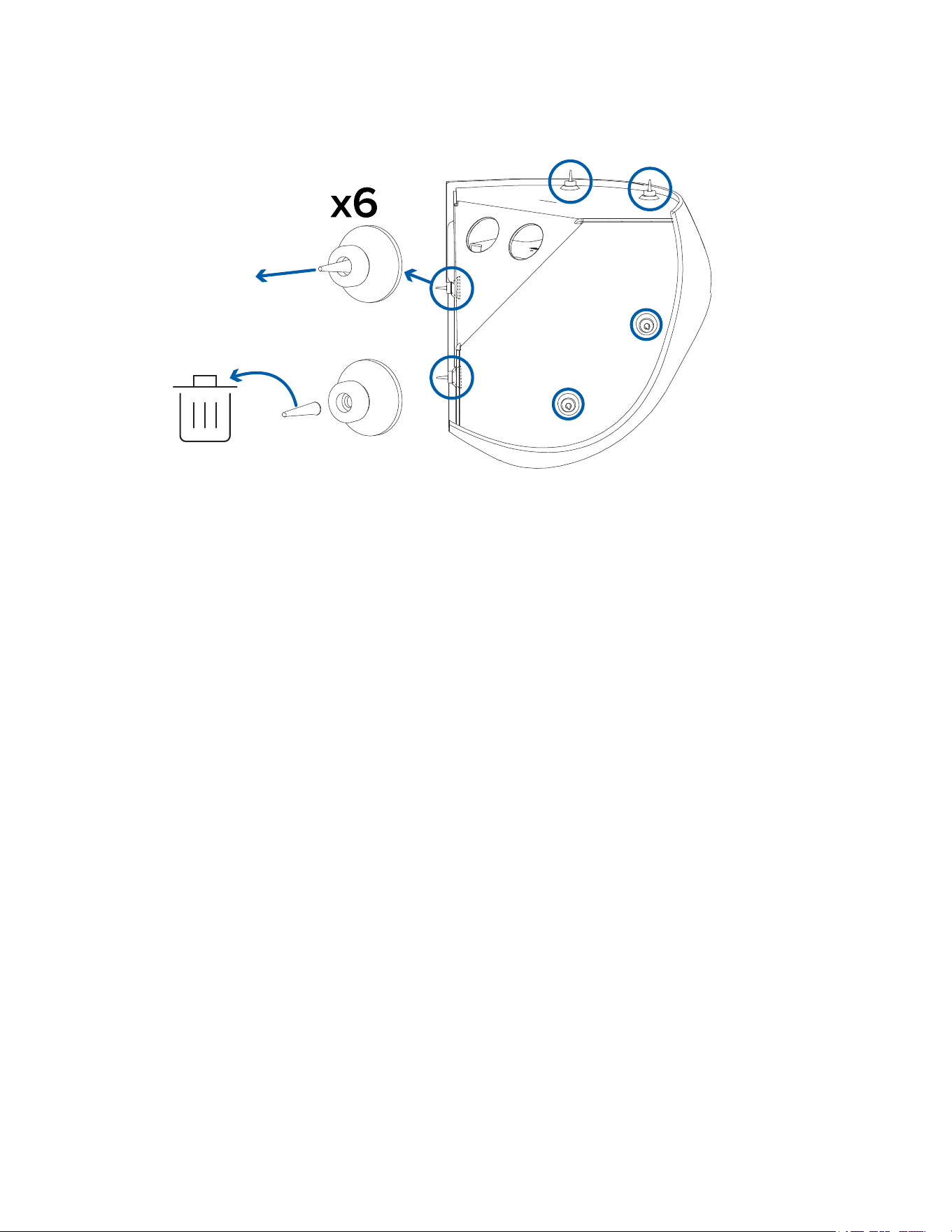
Preparing the Mounting Grommets
Thereare6mountingholesinthecamerahousing.Eachmountingholeisfilledbyagrommettohelp
protectthemountingpointsfromwaterordust.SeeOverviewformoreinformationthemountinghole
locations.
1. Determinewhichmountingholesyouwillusetomountthecamera.
Pelcorecommendsusingall6mountingholestosecureyourcamera,toensurethecamerais
mountedsecurelyandtomakethecameraligature-proof.
Sarix Corner Camera 3 Series Installation Manual
C6714M | 02/22
12
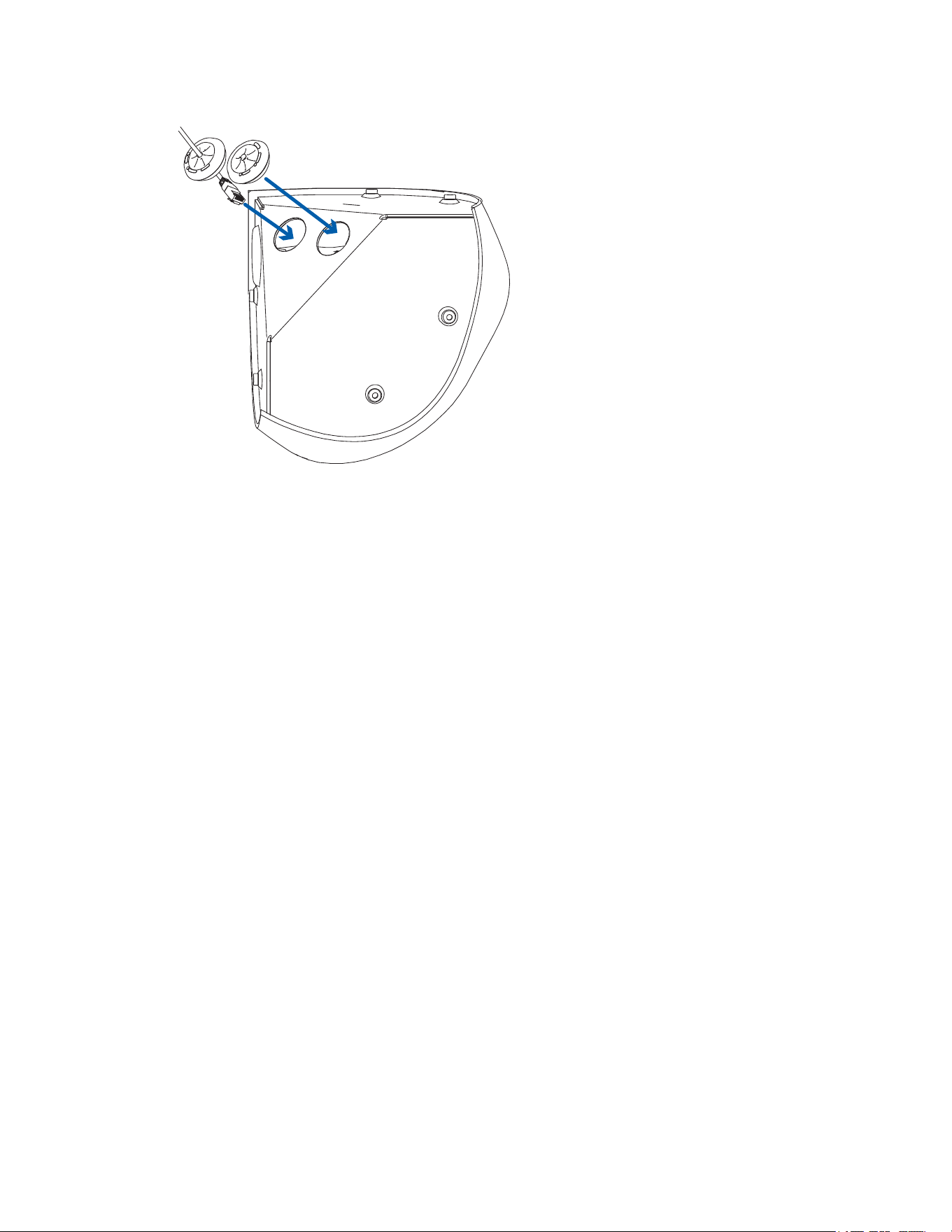
2. Pullthepinsoutofthegrommetsforthemountingholesthatwillbeused.
Mounting and Aiming Video Analytics Cameras
WheninstallingaPelcoSmartanalyticscamera,followthelistedmountingandaimingrecommendations
tomaximizethecamera'sanalyticscapabilities:
l
Thecamerashouldbeinstalledabove2.74m(9feet).
l
Thecamerashouldtiltdownwardsnomorethan45degrees.
l
Thecameraimageshouldbelevelwiththehorizonline.
l
Thecamerashouldbemountedtoastablesurfacetominimizethephysicalmovementofthe
cameraafterinstallation.
Formoredetails,seetheDesigning a Site with Pelco Smart Analytics Guide.Thisdocumentisavailable
onthePelcowebsite.
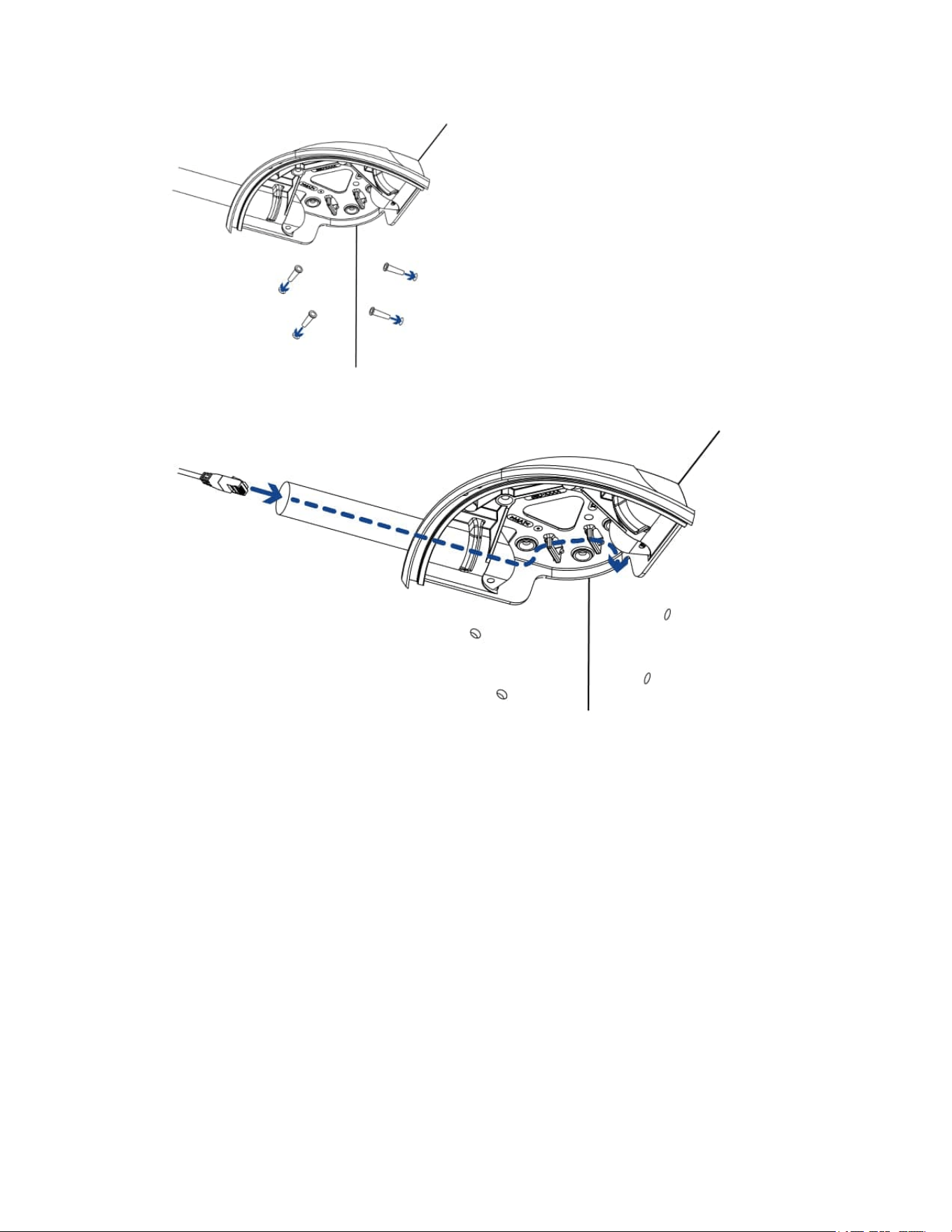
Inserting Cables through the Sealing Grommet
Toprotectthecameraandcomponentsfromingressofdustormoisture,youmustpulltherequired
cablesthroughthesealinggrommet(s)includedwiththecameraforthecableentryholes.
1. PullthetabonthegrommettoopenaholefortheEthernetcable.
2. PushanEthernetcablethroughthegrommetbyoneofthefollowingmethods:
a. IftheEthernetcableisuncrimped,pushthecablethroughthegrommet.
b. IftheEthernetcableisalreadycrimped,placethegrommetpiercingcapontheEthernet
connectorthenpushthecablethroughthegrommet.
Sarix Corner Camera 3 Series Installation Manual
C6714M | 02/22
13
Ensurethattheorientationofthecableandgrommetmatchestheoneshownintheimage.
3. Pushanyotherrequiredcablesthroughthesecondgrommet.
Ifyouwillpullmultiplecablesthroughthesealinggrommet,applysiliconesealanttosealanygaps
inthegrommet.
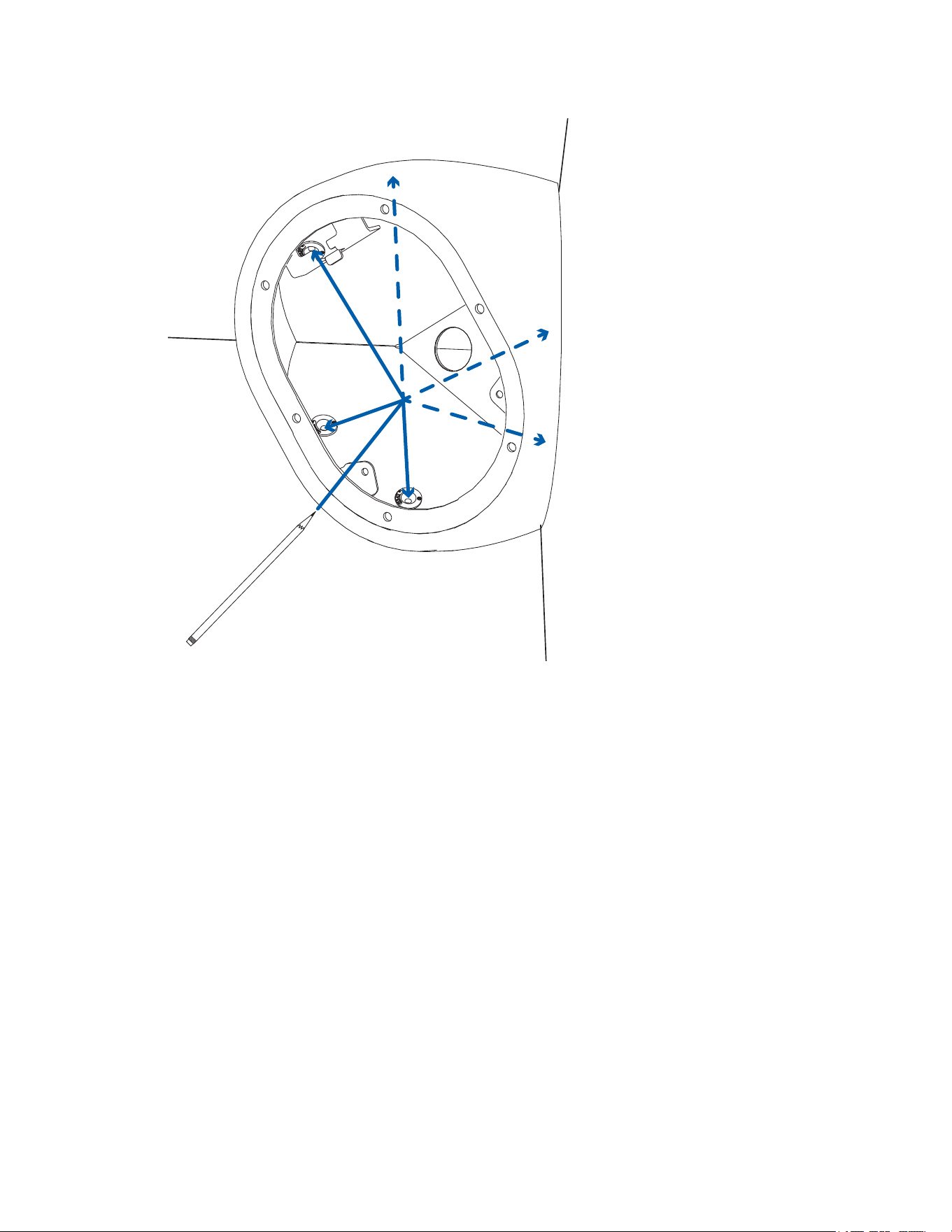
Mounting the Corner Camera Base
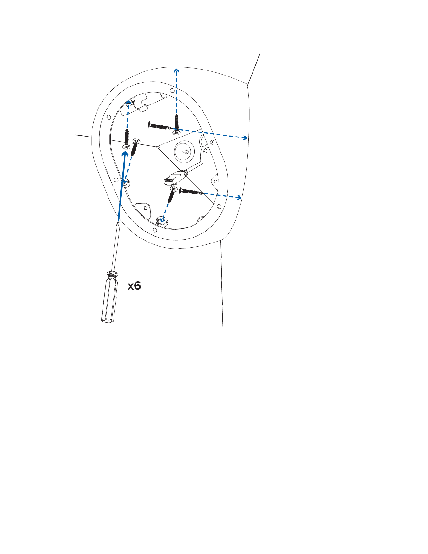
Performthefollowingstepstomountthecamerabase.
1. Placethebaseintothemountinglocation.Makesurethatthemountinggrommetpinshavebeen
removed.Formoreinformation,seePreparing the Mounting Grommets.
2. Useapenorpenciltomarkthespotsthatwillbedrilledintothemountingsurfaceforthemounting
screws.
Sarix Corner Camera 3 Series Installation Manual
C6714M | 02/22
14
Pelcorecommendsusingall6mountingholestosecureyourcamera,toensurethecamerais
mountedsecurelyandtomakethecameraligature-proof.
3. Removethebasefromthemountingsurface.Drillthe6mountingholesandonecableentryhole
intothemountingsurface.
Sarix Corner Camera 3 Series Installation Manual
C6714M | 02/22
15
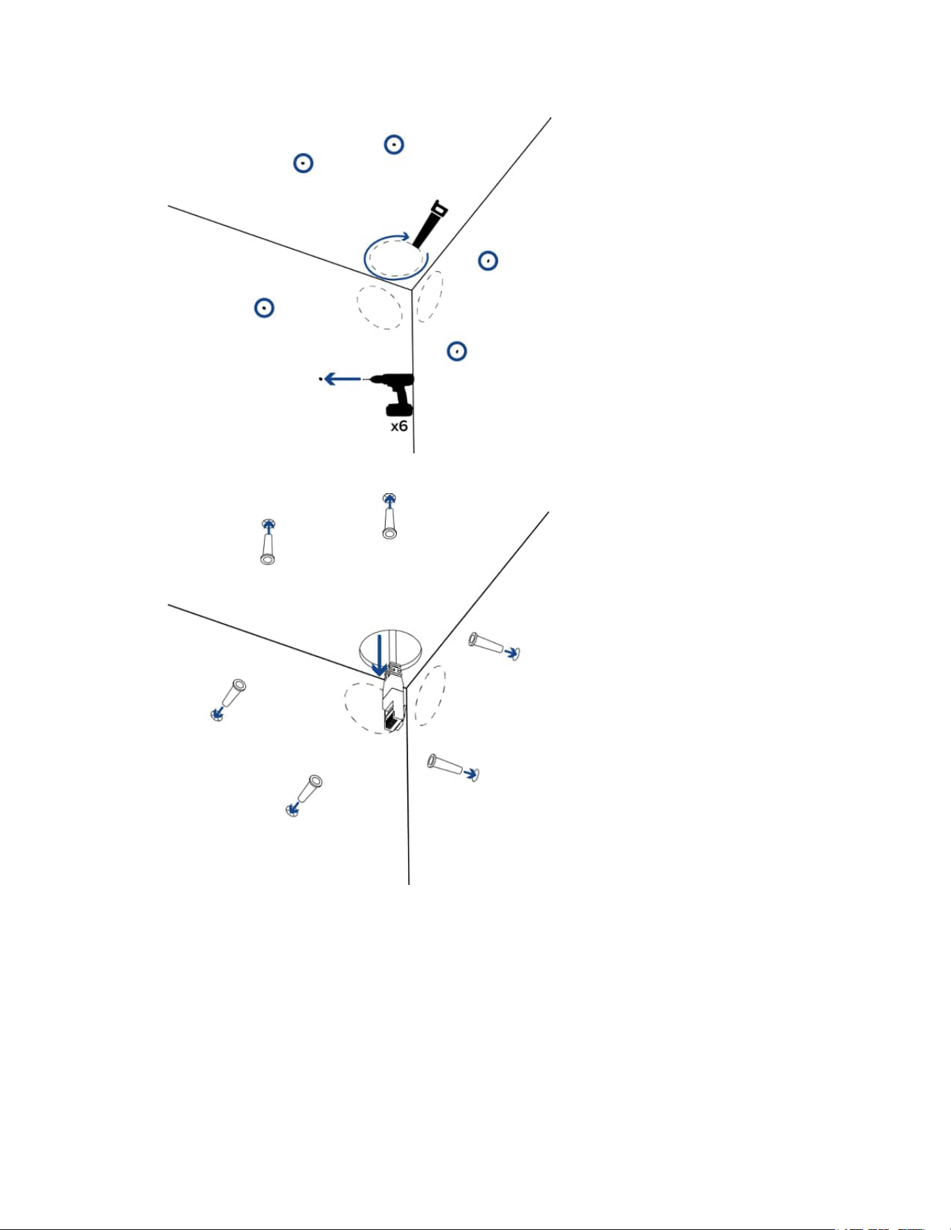
4. Insertthewallanchorsintothemountingholes.
5. Pulltherequiredcablesthroughthecableentryhole.
6. Insertthesealinggrommetswiththerequiredcablespulledthroughintothecableentryholeson
thebackofthecamerabase.Formoreinformation,seeInserting Cables through the Sealing
Grommet.
Sarix Corner Camera 3 Series Installation Manual
C6714M | 02/22
16
7. Placethecamerabaseinthemountinglocationanddrivethe6mountingscrewstosecureitin
place.
Sarix Corner Camera 3 Series Installation Manual
C6714M | 02/22
17
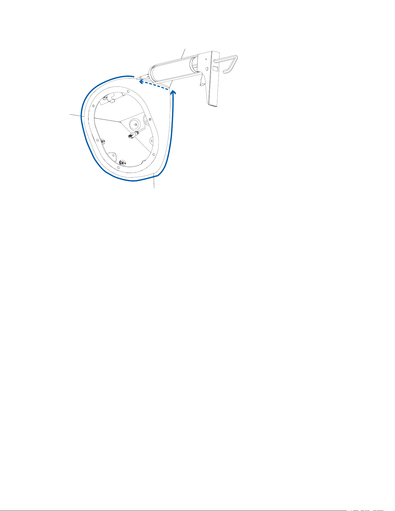
8. Applysiliconesealantaroundtheedgesofthecamerabasetopreventmoisturefromenteringthe
mountingsurface.
Sarix Corner Camera 3 Series Installation Manual
C6714M | 02/22
18
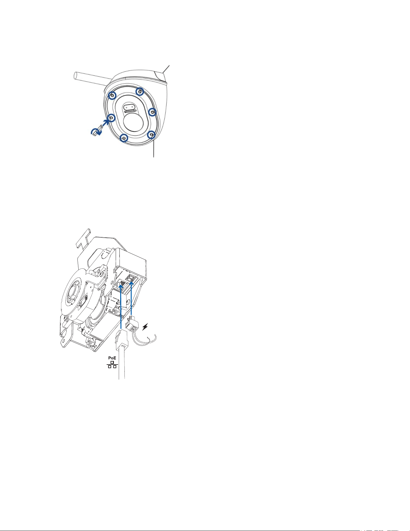
Connecting Cables
1. Ifexternalinputoroutputdevicesarepartoftheinstallation(forexample:doorcontacts,relays,
etc.),connectthedevicestotheI/Oconnectorblock.
2. Ifthebuilt-inmicrophonewillbeused,thefactory-intalledaudiocablewillhavetobeconnectedto
theinsideofthefrontcover.
3. ConnectanetworkcabletotheEthernetport(RJ-45connector).
TheLinkLEDindicatorwillturnononceanetworklinkhasbeenestablished.
4. Connectpowerusingoneofthefollowingmethods:
o
PoweroverEthernet(PoE)Class3—IfPoEisavailable,theLEDswillturnon.
o
ExternalPower—Connectanexternal12VDCor24VACpowersourcetothepower
connectorblock.
5. CheckthattheConnectionStatusLEDindicatorindicatesthecorrectstate.Formoreinformation,
seeConnection Status LED Indicator.
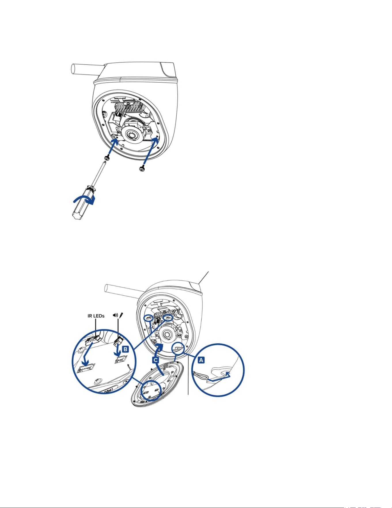
Mounting the Camera Gimbal to the Base
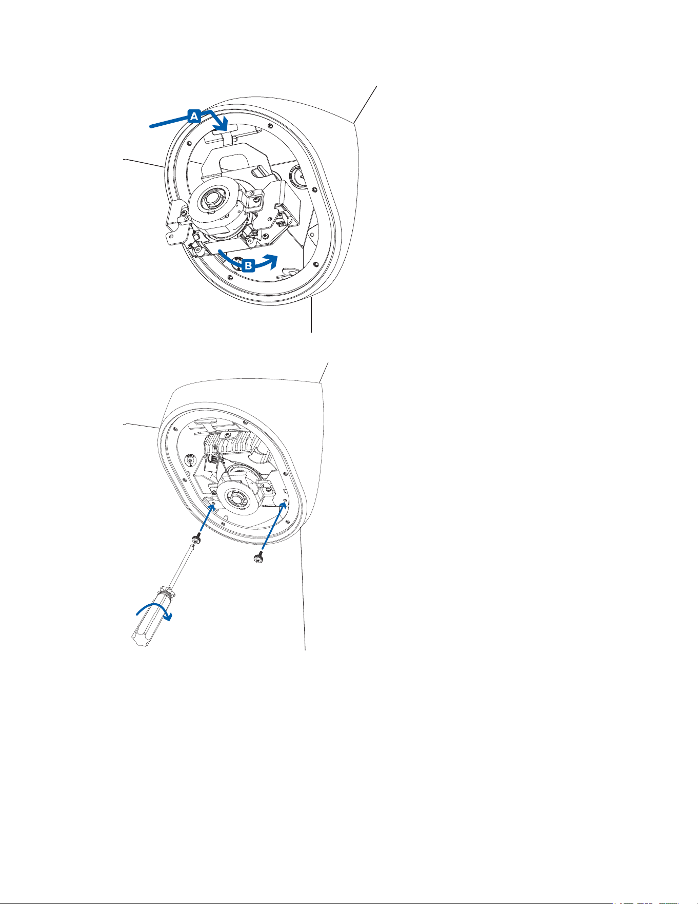
Oncethecamerabaseismountedinplace,installthegimbalbackintothebase:
1. Slidethehookatthetopofthegimbalintotheslotatthetopofthecamerabase(A)andthen
rotatethegimbalintothehousing(B).
Sarix Corner Camera 3 Series Installation Manual
C6714M | 02/22
19
2. Useaphillipsscrewdrivertotightenthe2screwsandsecurethegimbaltothecamerabase.
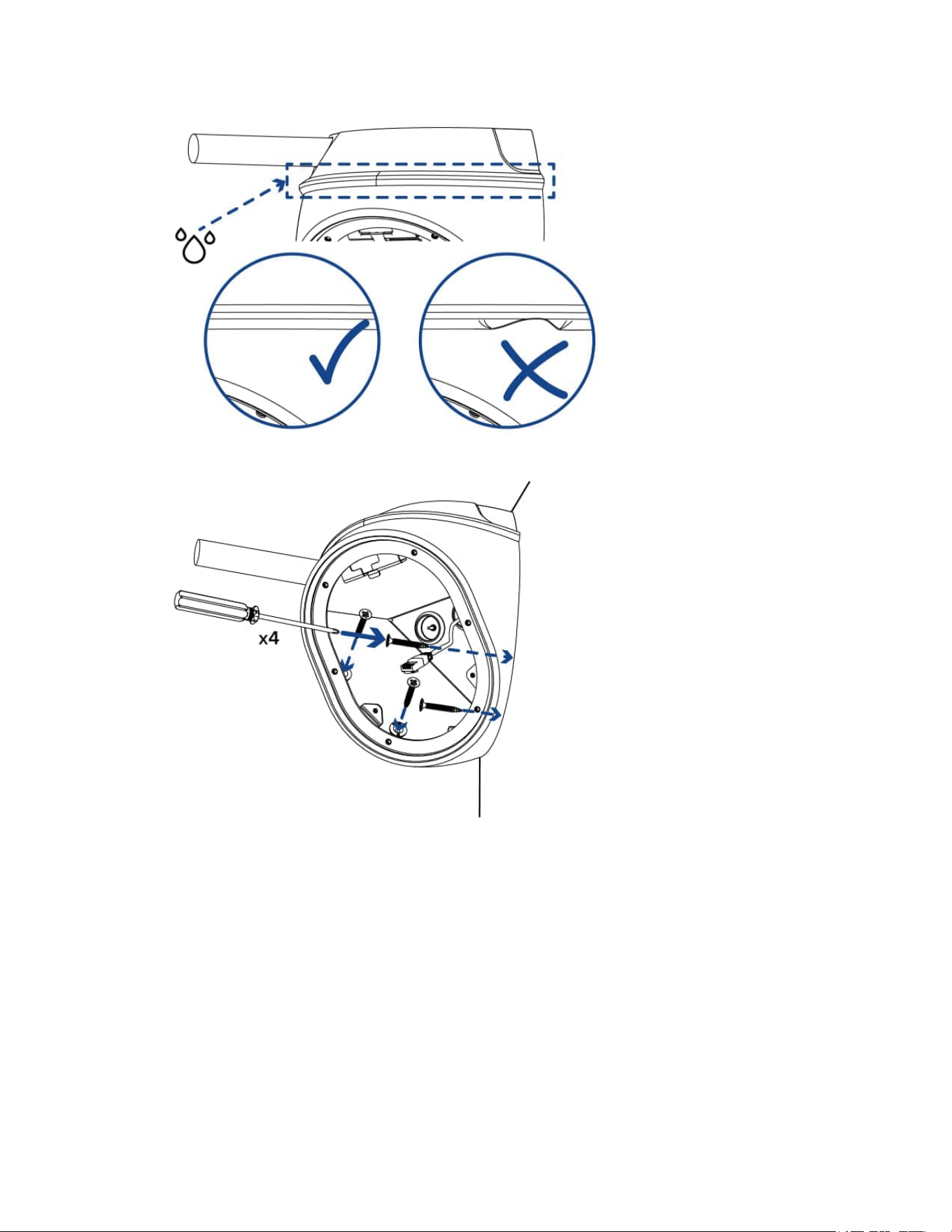
Installing the Front Cover
Becarefulnottotouchorscratchthedomebubble.Anymarksorfingerprintsonthedomebubblewill
causeunwantedreflections.
Sarix Corner Camera 3 Series Installation Manual
C6714M | 02/22
20
1. Attachthelanyardtothelanyardhookatthebottomofthecamerabase(A).
2. ConnecttheLEDcabletotheconnectoronthefrontcover(B).
3. Ifyouareusingthebuilt-inmicrophone,connectthemicrophoneaudiocabletotheconnectoron
thefrontcover(B).
4. Fitthefrontcoverintoplace(C).
5. Securethefrontcovertothecamerabasebytighteningthe6screwswiththesupplieddriver.
Initializing a Camera Username and Password
Youmustcreateauserwithadministratorprivilegesbeforethecameraisoperational.
Thenewusercanbecreatedusingthefollowingmethods:
l
Camera'swebinterface.Enterthecamera'sIPaddressinawebbrowsertoaccesstheweb
interface.Formoreinformation,seethePelcoSarixCornerCamera3SeriesOperationsManual.
Ifthecameraisinthefactorydefaultstate,youwillberedirectedtotheNewUserpagetocreate
anadministratoruser:
Sarix Corner Camera 3 Series Installation Manual
C6714M | 02/22
21
1. EnteranewUserNameorkeepthedefaultadministratorname.
2. EnteranewPasswordfortheuser.Itisrecommendedtouseasecureandcomplex
password.
3. Confirmthenewpassword.
4. Forthefirstuser,AdministratormustbeselectedintheSecurityGroupdrop-downmenu.
5. ClickApply.Aftercreatingtheuser,youwillbeaskedtologin.
l
CameraConfigurationTool:discoveredcamerasthatareidentifiedby willrequireafirstuser
tobeset.SelecttheAdminUserstabtocreatethefirstuser.Formoreinformation,seethe
Camera Configuration Tool User Guide.
Note:Setupthefirstuserthroughthecamera'sWebInterfaceorCameraConfigurationTool
beforeyouconnectthecameratoaVMS.
Assigning an IP Address
ThedeviceautomaticallyobtainsanIPaddresswhenitisconnectedtoanetwork.
IfthedevicecannotobtainanIPaddressfromaDHCPserver,itwilluseZeroConfigurationNetworking
(Zeroconf)tochooseanIPaddress.WhensetusingZeroconf,theIPaddressisinthe169.254.0.0/16
subnet.
TheIPaddresssettingscanbechangedusingoneofthefollowingmethods:
l
Device'swebbrowserinterface:http://<camera IP address>/.
l
NetworkVideoManagementsoftwareapplication.
l
ARP/Pingmethod.Formoreinformation,seeSetting the IP Address Using the ARP/Ping Method.
Accessing the Live Video Stream
Livevideostreamcanbeviewedusingoneofthefollowingmethods:
l
Webbrowserinterface:http://< camera IP address>/.
l
NetworkVideoManagementsoftwareapplication.
(Optional) Configuring microSD Card Storage
Tousethecamera'sSDcardstoragefeature,youmustinsertamicroSDcardintothecardslot.
ItisrecommendedthatthemicroSDcardhaveawritespeedofclass10orbetter.IfthemicroSDcard
doesnotmeettherecommendedwritespeed,therecordingperformancemaysufferandresultinthe
lossofframesorfootage.
1. InsertamicroSDcardintothecamera.
DonotforcethemicroSDcardintothecameraoryoumaydamagethecardand
thecamera.
2. Accessthecamera’swebinterfacetoenabletheonboardstoragefeature.Formoreinformation,
seethePelcoSarixCornerCamera3SeriesOperationsManual.
Focusing the Camera
Ensurethisprocedureisperformedafterthefrontcoverisinstalled,soyoucanaccommodateforthe
focusshiftcausedbythelensbubble.

Sarix Corner Camera 3 Series Installation Manual
C6714M | 02/22
22
Inthecamerawebbrowserinterface,usethecamera'sImageandDisplaysettingstofocusthecamera.
1. ClickAutoFocustofocusthelens.
2. Usethefocusnearandfarbuttonstomanuallyadjustthefocus.
Configuring the Camera
Afterthecameraisinstalled,configureitusingtheinstructionsinthecurrentversionofthePelcoSarix
CornerCamera3SeriesOperationsManual.
Sarix Corner Camera 3 Series Installation Manual
C6714M | 02/22
23
Installation with the Conduit Box Accessory
Theconduitgangboxisanoptionalmountingaccessorythatcanbeusedforinstallationswherethe
cablesarenotabletocomethroughthewallandacableconduitisnecessary.OrderCNBX-1001to
mountyourcornercamerawiththeconduitbox.
Mounting the Conduit Gang Box
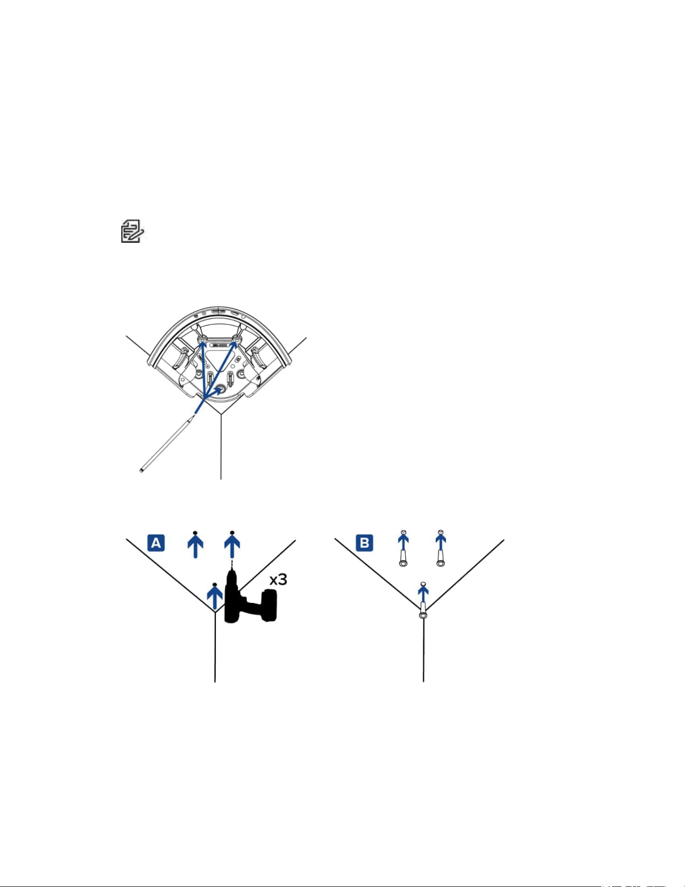
Performthefollowingstepstomounttheconduitgangboxmountingaccessory.
1. Placetheconduitboxontothemountinglocation.
Note
:Becautiousofunevenwallswhenmountingtheconduitboxandcornercamera.
Unevenwallsmaymakeitdifficulttomountthecamera.Beforemountingtheconduitbox,
placetheconduitboxandthecamerainthemountinglocationtoensuretheycanbe
mountedflushtotheceilingandbothwallswithoutlargegaps.
2. Useapenorpenciltomarkthe3spotsthatwillbedrilledintotheceilingforthemountingscrews.
3. Removethebasefromthemountingsurface.Drillthe3mountingholesintothemountingsurface
(A).
4. Insertthewallanchorsintothemountingholes(B).
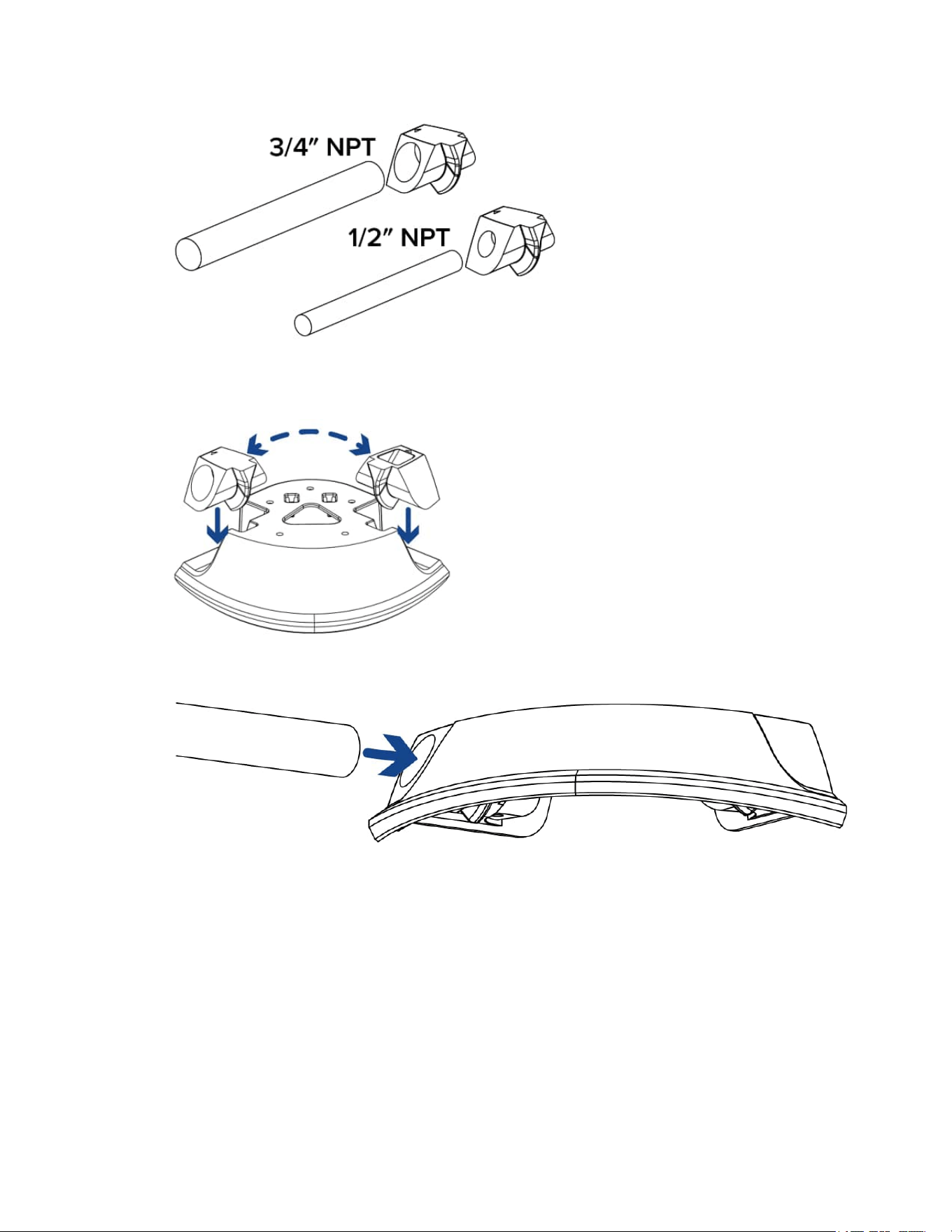
5. Determinewhichsizeconduitpipeyouwilluseforyourcables.Theconduitboxcomeswith2
sizesofconduitentrypointstouse:3/4"NPTor1/2"NPT.
Sarix Corner Camera 3 Series Installation Manual
C6714M | 02/22
24
6. Inserttheconduitentrypointintotheconduitboxbypushingdown.Insertthematchingsolidpiece
ontheothersideoftheconduitbox.Thesidesarereversiblesothecableconduitcancomefrom
eitherdirection.
7. Inserttheconduitpipeintotheconduitentrypoint.
8. Placetheconduitboxagainstthemountingsurfaceanddrivethe3mountingscrewsintosecureit
inplace.

Sarix Corner Camera 3 Series Installation Manual
C6714M | 02/22
25
Mounting the Camera Base to the Conduit Box
Performthefollowingstepstomountthecornercamerabasetotheconduitbox.
1. Beforemountingthecamerabase,youwillneedtoprepareitformounting.Performthesesteps
first:
a. Removing the Front Cover and Gimbal
b. Preparing the Mounting Grommets.Fortheconduitboxinstallationonly4mountinggrommet
pinsneedtoberemoved.Thetwotoppinsformountingtotheceilingcanremaininplace.
2. Placethebaseintothemountinglocationupagainsttheinstalledconduitbox.Useapenorpencil
tomarkthespotsthatwillbedrilledintothemountingsurfaceforthemountingscrews.
Sarix Corner Camera 3 Series Installation Manual
C6714M | 02/22
26
3. Removethebasefromthemountingsurface.Drillthe4mountingholesintothemountingsurface.
4. Insertthewallanchorsintothemountingholes.
Sarix Corner Camera 3 Series Installation Manual
C6714M | 02/22
27
5. Pulltherequiredcablesthroughthecableconduitpipe.UsetheEthernetcableclipstokeepthe
cableinplace.
6. Insertthesealinggrommetswiththerequiredcablespulledthroughintothecableentryholeson
thebackofthecamerabase.Formoreinformation,seeInserting Cables through the Sealing
Grommet.
Sarix Corner Camera 3 Series Installation Manual
C6714M | 02/22
28
7. Placethecamerabaseinthemountinglocation.
8. Checktherubbergasketwherethecameraandconduitboxjoin.Thegasketshouldfiteasilyover
thetopedgeofthecornercamera.Adjusttocorrectanywherethegasketispinched.
Sarix Corner Camera 3 Series Installation Manual
C6714M | 02/22
29
9. Drivethe4mountingscrewstosecurethecamerainplace
10. Applysiliconesealantaroundtheedgesofthecamerabaseandconduitboxtopreventmoisture
fromenteringthemountingsurface.
Sarix Corner Camera 3 Series Installation Manual
C6714M | 02/22
30
Mounting the Camera Gimbal
Oncethecamerabaseismountedinplace,installthegimbalbackintothebase:
1. ConnecttheEthernetcableandanyothercablesrequired.FormoreinformationseeConnecting
Cables.
2. Slidethehookatthetopofthegimbalintotheslotatthetopofthecamerabase(A)andthen
rotatethegimbalintothehousing(B).
Sarix Corner Camera 3 Series Installation Manual
C6714M | 02/22
31
3. Useaphillipsscrewdrivertotightenthe2screwsandsecurethegimbaltothecamerabase.
Installing the Front Cover
Becarefulnottotouchorscratchthedomebubble.Anymarksorfingerprintsonthedomebubblewill
causeunwantedreflections.
1. Attachthelanyardtothelanyardhookatthebottomofthecamerabase(A).
2. ConnecttheLEDcabletotheconnectoronthefrontcover(B).
3. Ifyouareusingthebuilt-inmicrophone,connectthemicrophoneaudiocabletotheconnectoron
thefrontcover(B).
4. Fitthefrontcoverintoplace(C).
Sarix Corner Camera 3 Series Installation Manual
C6714M | 02/22
32
5. Securethefrontcovertothecamerabasebytighteningthe6screwswiththesupplieddriver.
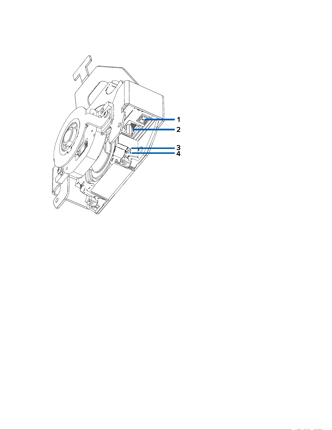
Cable Connections
Connecting External Power
IfPoEisnotavailable,thecameraneedstobepoweredthroughtheremovablepowerconnectorblock.
Refertothediagrambelowforthelocationofthepowerconnectorblock.Thegimbalwillneedtobe
removedfromthehousingtoaccessthepowerconnectorblock.
Toconnectpowertothepowerconnectorblock,completethefollowingsteps:
1. Removethepowerconnectorblockfromthecamera.
2. Removetheinsulationfrom¼”(6mm)ofthepowerwires.Donotnickordamagethewires.
3. Insertthetwopowerwiresintothetwoterminalsonthepowerconnectorblock.Theconnection
canbemadewitheitherpolarity.
Useasmallslotted(5/64”or2mmbladewidth)screwdrivertoloosenandtightentheterminals.
4. Attachthepowerconnectorblockbackintothecamera.
Sarix Corner Camera 3 Series Installation Manual
C6714M | 02/22
33
ThisproductisintendedtobesuppliedbyaULListedPowerUnitmarked“Class2”or“LPS”or
“LimitedPowerSource”withoutputrated12VDCor24VAC,13Wmin.orPoE,13Wmin.
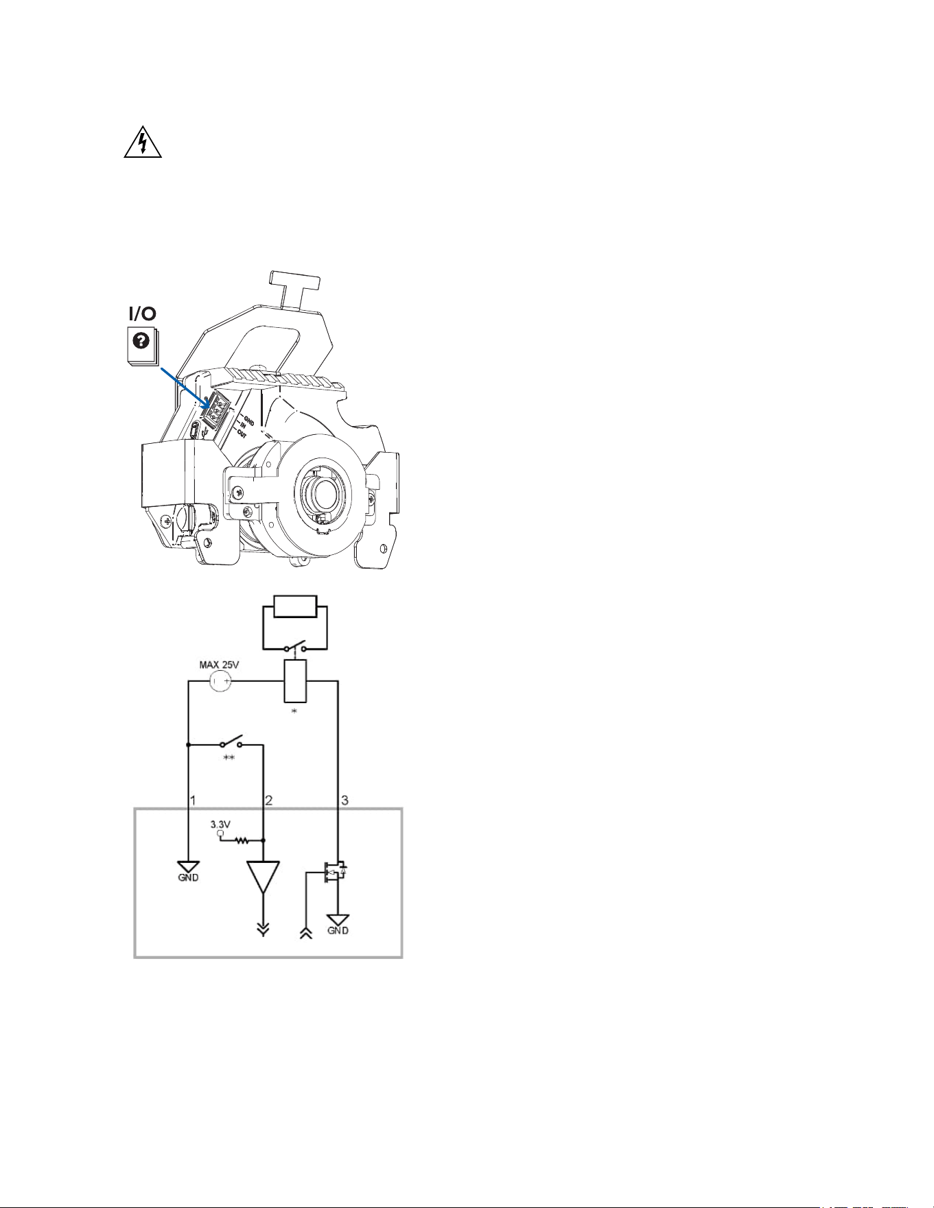
Connecting to External Devices
ExternaldevicesareconnectedtothecamerathroughtheI/Oterminalblock.ThepinoutfortheI/O
terminalblockisshowninthefollowingdiagram:
1. Ground
2. Input—Toactivate,connecttheInputtotheGroundpin.Todeactivate,leavedisconnectedor
applybetween3-15V.

Sarix Corner Camera 3 Series Installation Manual
C6714M | 02/22
34
3. Output—Whenactive,OutputisinternallyconnectedwiththeGroundpin.Circuitisopenwhen
inactive.Maximumloadis25VDC,120mA.
l
*—Relay
l
**—Switch
Connection Status LED Indicator
Onceconnectedtothenetwork,thegreenConnectionStatusLEDindicatorwilldisplaytheprogressin
connectingtotheNetworkVideoManagementsoftware.
ThefollowingtabledescribeswhattheLEDindicatorshows:
Connection State Connection
Status LED
Indicator
Description
Obtaining
IPAddress
Oneshortflash
everysecond
AttemptingtoobtainanIPaddress.
Discoverable Twoshortflashes
everysecond
ObtainedanIPaddressbutnotconnectedtothe
NetworkVideoManagementsoftware.
Upgrading
Firmware
Twoshortflashes
andonelongflash
everysecond
Updatingthefirmware.
Connected On ConnectedtotheNetworkVideoManagementsoftware.
ThedefaultconnectedsettingcanbechangedtoOffusing
thecamera'swebuserinterface.Formoreinformation,see
thePelcoSarixCornerCamera3SeriesOperationsManual.
Troubleshooting Network Connections and LED Behavior
ForanyofthebelowLEDbehaviors,ensurethatthecameraisgettingpowerandisusingagood
networkcablebeforetryinganothersolution.
LED Behavior Suggested Solution
GreenLEDisoffandamberison Performafactoryresetofthecamerausingthephysical
firmwarerevertbutton.Resettingthroughthecamera'sweb
interfacewillnotproducethedesiredresult.
BothLEDsareoffandthecameraisnot
connectedorstreamingvideo
ChecktheGeneralsetuppageinthecamera'swebinterface
toensuretheLEDsarenotdisabled.
IftheLEDsarenotdisabled,performafactoryresetofthe
camerausingthephysicalfirmwarerevertbutton.Resetting
throughthecamera'swebinterfacewillnotproducethe
desiredresult.
BothLEDsareblinkingseveraltimesat
thesametime,thenpauseandrepeat
theblinking
Performafactoryresetofthecamerausingthephysical
firmwarerevertbutton.Resettingthroughthecamera'sweb
interfacewillnotproducethedesiredresult.
AdifferentLEDblinkingpatternthan
Performafactoryresetofthecamerausingthephysical
Sarix Corner Camera 3 Series Installation Manual
C6714M | 02/22
35
LED Behavior Suggested Solution
thosedescribedabove
firmwarerevertbutton.Resettingthroughthecamera'sweb
interfacewillnotproducethedesiredresult.
Resetting to Factory Default Settings
Ifthedevicenolongerfunctionsasexpected,youcanchoosetoresetthedevicetoitsfactorydefault
settings.
Usethefirmwarerevertbuttontoresetthedevice.Thefirmwarerevertbuttonisshowninthefollowing
diagram:
1. Ensurethedeviceispoweredon.
2. Usingastraightenedpapercliporsimilartool,gentlypressandholdthefirmwarerevertbutton.
3. Releasethebuttonafterthreeseconds.
Donotapplyexcessiveforce.Insertingthetooltoofarmaydamagethecamera.
Setting the IP Address Using the ARP/Ping Method
CompletethefollowingstepstoconfigurethecameratouseaspecificIPaddress:
Note:TheARP/PingMethodwillnotworkiftheDisable setting static IP address through
ARP/Ping methodcheckboxisselectedinthecamera'swebbrowserinterface.Formore
information,seethePelcoSarixCornerCamera3SeriesOperationsManual.
1. LocateandmakenoteoftheMACAddress(MAC)listedontheSerialNumberTagforreference.
2. OpenaCommandPromptwindowandenterthefollowingcommands:
a. arp -s <New Camera IP Address> <Camera MAC Address>
Forexample:arp -s 192.168.1.10 00-18-85-12-45-78
b. ping -l 123 -t <New Camera IP Address>
Forexample:ping -l 123 -t 192.168.1.10
3. Rebootthecamera.
4. ClosetheCommandPromptwindowwhenyouseethefollowingmessage:
Reply from <New Camera IP Address>: ...
Cleaning
Dome Bubble
Ifthevideoimagebecomesblurryorsmudgedinareas,itmaybebecausethedomebubblerequires
cleaning.
Tocleanthedomebubble:
l
Usehandsoaporanon-abrasivedetergenttowashoffdirtorfingerprints.
l
Useamicrofiberclothornon-abrasivefabrictodrythedomebubble.

Sarix Corner Camera 3 Series Installation Manual
C6714M | 02/22
36
Failuretousetherecommendedcleaningmaterialsmayresultinadamagedorscratcheddomebubble.
AdamageddomebubblemaynegativelyimpactimagequalityandcauseunwantedIRlightreflecting
intothelens.
Body
l
Useadryorlightlydampenedclothtocleanthecamerabody.
l
Donotusestrongorabrasivedetergents.
For More Information
Additionalinformationaboutsettingupandusingthedeviceisavailableinthefollowingguides:
l
PelcoSarixCornerCamera3SeriesOperationsManualavailableonthePelcowebsite:
www.pelco.com.
l
Camera Configuration Tool User Guide
Pelco Troubleshooting Contact Information
Forfurtherassistance,contactPelcoProductSupportat1-800-289-9100(USAandCanada)or+1-559-
292-1981(international).
Donottrytorepairtheunityourself.Leavemaintenanceandrepairstoqualifiedtechnicalpersonnel
only.

Sarix Corner Camera 3 Series Installation Manual
Pelco, Inc.
625 W. Alluvial Ave., Fresno, California 93711 United States
(800) 289-9100 Tel
(800) 289-9150 Fax
+1 (559) 292-1981 International Tel
+1 (559) 348-1120 International Fax
www.pelco.com
Pelco, the Pelco logo, and other trademarks associated with Pelco products referred to in this publication are trademarks of Pelco,
Inc. or its affiliates. ONVIF and the ONVIF logo are trademarks of ONVIF Inc. All other product names and services are the property of
their respective companies. Product specifications and availability are subject to change without notice.
© Copyright 2022, Pelco, Inc. All rights reserved.