Thank you very much for purchasing this Air Conditioner. Please
read this carefully before installing use and installation instructions
and using this appliance and keep this manual for future reference.

NOTE:
● This air conditioner is designed for the following temperatures.
It should be operated within this range:
DC Inverter Unitary Series
Mode
Outdoor operation temperature range (℃)
Maximum
Minimum
Cooling Operation
-10
Heating Operation
-15
● Storage condition: Temperature -25~60℃
Humidity 30%~80%
46
24
Contents
Safety Precautions..........................................................................................................................................1
Refrigerant Flow Diagram ..............................................................................................................................8
Electrical Wiring Diagram...............................................................................................................................9
Installation Instructions................................................................................................................................10
Transportation and Handling before Installation ..........................................................................................10
Installation Location Selection......................................................................................................................10
Drainage Elbow and Drain Hose Installation................................................................................................11
Outdoor Unit Installation...............................................................................................................................11
Refrigerant Piping .......................................................................................................................................12
Wiring ...........................................................................................................................................................15
Trial Run ......................................................................................................................................................17

1
1.This air conditioner uses new refrigerant HFC (R32).
2.The max. working pressure is 4.3MPa (R22: 3.1MPa). Some of the piping and installation
and service tools are special.
Please read these SAFETY PRECAUTIONS carefully to ensure correct installation.
·Be sure to use a dedicated power circuit, and do not put other loads on the power supply.
·Be sure to read these SAFETY PRECAUTIONS carefully before installation.
·Be sure to comply with SAFETY PRECAUTIONS of installation manual, because it contains
important safety guidelines. Definitions for identifying hazards levels are provided below with their
respective safety symbols.
WARNING: Hazards or unsafe practices which COULD result in severe personal injury or death.
CAUTION: Hazards or unsafe practices which COULD result in minor personal injury or product
or property damage.
·File indoor and outdoor unit manual away for future reference.
·Installation should be performed by the qualified personnel.
Incomplete installation may cause damage due fire, electric shock or water leakage.
·Perform the installation properly by referring to the installation manual.
Improper installation may cause personal injury fire, electric shock, unit falling or water leakage.
·Install the air conditioner on a solid base that can support the unit weight.
An inadequate base or improper installation may cause injury in the event the unit falls off the base.
·Wiring must be done by the qualified electrician. All the electric works must be performed in
accordance with national wiring regulations and local electrical codes.
·Use the specified type of wire for electrical connections safely.
Firmly clamp the interconnecting wires so that their terminals receive no external stresses.
·Use a cable long enough to cover the entire distance with no connection. Do not connect multiple
devices to the same AC power supply.
Doing so it may result in bad contact, poor insulation, or over current resulting in fire or electric shock.
·After all installations are completed, make sure that there are no refrigerant leaks.
Leaked refrigerant gas may generate harmful substance when the gas comes in contact with a heat
source, or open flame.
·If the power supply circuit capacity or electrical work is not in place, it may cause a fire or electric
shock.
·Install the electrical cover to the indoor unit and the service panel to the outdoor unit securely.
·If the electrical cover on the indoor unit or the service panel of the outdoor unit are not installed
properly, it could result in fire or electric shock due to dust water, etc.
·Disconnect the main power supply before the installation of indoor electronic PCB or wiring.
Failure to do so will result in electric shock.
· avoid people or other small animals contact with Select outdoor unit installation location carefully,
electrical components. Please keep the surrounding environment of the outdoor unit clean and tidy.
·When installing or relocating the unit, make sure that no substance other than the specified
refrigerant (R32) enters the refrigerant circuit.
Any presence of foreign substance such as air can cause abnormal pressure rise or an explosion.
WARNING
Safety Precautions

2
CAUTION
·Perform grounding
Do not connect the earth wire to a gas pipe, water pipe, lightning rod or telephone earth wire.
Defective grounding could cause an electric shock.
·Do not install the unit in a place where an inflammable leak is possible.
If gas leaks and accumulates in the area surrounding the unit, it could cause an explosion.
·Tighten a flare nut with a torque wrench as specified in this manual.
When fastened too tight, a flare nut may break after a long period, thereby causing refrigerant leakage.
·Install an earth leakage breaker depending on the installation place(where local code requires humid).
If an earth leakage breaker is not installed, it could cause an electric shock.
·Perform the drainage/piping work securely according to the installation manual.
·If there is a defect in the drainage/piping work, water could leak from the unit and household goods
could become wet and damaged.
Safety Precautions
·Do not let air enter the refrigeration system or discharge refrigerant when moving the air conditioner.
·The installation instructions for appliances that are intended to be permanently connected to fixed
wiring, and have a leakage current that may exceed 10 mA, shall state that the installation of a
residual current device (RCD) having a rated residual operating current not exceeding 30 mA is
advisable.
·This appliance is not intended for use by persons (including children) with reduced physical, sensory
or mental capabilities, or lack of experience and knowledge, unless they have been given supervision
or instruction concerning use of the appliance by a person responsible for their safety.
Children should be supervised to ensure that they do not play with the appliance.
·If the appliance has permanently fixed wiring, the appliance must be fitted with means for disconnection
from the supply mains having a contact separation in all poles that provide full disconnection under
over voltage category III conditions, and these means must be incorporated in the fixed wiring in
accordance with the wiring rules.
·If the supply cord is damaged, it must be replaced by a qualified contractor, its service agent or similarly
qualified persons in order to avoid a hazard.
·The appliance shall be installed in accordance with national wiring regulations.
·Servicing shall only be performed as recommended by the equipment manufacturer.
Safety instructions
·The method of connection of the appliance to the electrical supply and interconnection of separate
components is detailed in below part. The wiring diagram with a clear indication of the connections
and wiring to external control devices and supply cord is detailed in below part. The cord of the
H07RN-F type or the electrically equivalent type must be used for power connection and
interconnection between outdoor unit and indoor unit. The size of the cord is detailed in below part.
·In order to avoid a hazard due to inadvertent resetting of the thermal cut-out, this appliance must not
be supplied through an external switching device, such as a timer, or connected to a circuit that is
regularly switched on and off by the utility.
·It is necessary to allow disconnection of the appliance from the electrical supply after installation.
The disconnection may be achieved by incorporating a switch in the fixed wiring in accordance with
the wiring rules. During service and when replacing parts, be sure to disconnect the appliance from
its power source. If the disconnection is not foreseen, and provide a disconnection with a locking
system in the isolated position.
·Details of type and rating of fuses, or rating of circuit breakers / ELB is detailed in below parts.
·The information of dimensions of the space necessary for correct installation of the appliance
including the minimum permissible distances to adjacent structures is detailed in below details.
·This appliance is intended to be used by expert or trained technicians, in shops, in light industry and
in light commercial applications, or for commercial applications.
·Instructions on additional charging of refrigerants are detailed below.
Safety Precautions
Precautions for using R32 refrigerant
3
The basic installation work procedures are the same as the conventional refrigerant (R22 or R410A).
However, pay attention to the following points:
WARNING
1.Transport of equipment containing flammable refrigerants.
Attention is drawn to the fact that additional transportation regulations may exist with respect to equipment containing
flammable gas. The maximum number of pieces of equipment or the configuration of the equipment, permitted to be
transported together will be determined by the applicable transport regulations.
2. Marking of equipment using signs
Signs for similar appliances (containing flammable refrigerants) used in a work area generally are addressed by local
regulations and give the minimum requirements for the provision of safety and/or health signs for a work location. All
required signs are to be maintained and employers should ensure that employees receive suitable and sufficient instruction
and training on the meaning of appropriate safety signs and the actions that need to be taken in connection with these signs.
The effectiveness of signs should not be diminished by too many signs being placed together. Any pictograms used should be
as simple as possible and contain only essential details.
3.Disposal of equipment using flammable refrigerants
Compliance with national regulations
4.Storage of equipment/appliances
The storage of equipment should be in accordance with the manufacturer's instructions.
5.Storage of packed (unsold) equipment
•Storage package protection should be constructed such that mechanical damage to the equipment inside the package will not
cause a leak of the refrigerant charge.
•The maximum number of pieces of equipment permitted to be stored together will be determined by local regulations.
6.Information on servicing
6-1 Checks to the area
Prior to beginning work on systems containing flammable refrigerants, safety checks are necessary to ensure that the risk of
ignition is minimized. For repair to the refrigerating system, the following precautions should be complied with prior to
conducting work on the system.
6-2 Work procedure
Work shall be undertaken under a controlled procedure so as to minimise the risk of flammable gas or vapour being present
while the work is being performed.
6-3 General work area
•All maintenance staff and others working in the local area shall be instructed on the nature of work being carried out. Work in
confined spaces shall be avoided.
•The area around the workspace shall be sectioned off. Ensure that the conditions within the area have been made safe by
control of flammable material.
6-4 Checking for presence of refrigerant
•The area shall be checked with an appropriate refrigerant detector prior to and during work, to ensure the technician is aware
of potentially flammable atmospheres.
•Ensure that the leak detection equipment being used is suitable for use with flammable refrigerants, i.e. non-sparking,
adequately sealed or intrinsically safe.
6-5 Presence of fire extinguisher
•If any hot work is to be conducted on the refrigeration equipment or any associated parts, appropriate fire extinguishing
equipment shall be available to hand.
•Have a dry powder or CO2 fire extinguisher adjacent to the charging area.
6-6 No ignition sources
•No person carrying out work in relation to a refrigeration system which involves exposing any pipe work that contains or has
contained flammable refrigerant shall use any sources of ignition in such a manner that it may lead to the risk of fire or
explosion.
•All possible ignition sources, including cigarette smoking, should be kept sufficiently far away from the site of installation,
repairing, removing and disposal, during which flammable refrigerant can possibly be released to the surrounding space.
•Prior to work taking place, the area around the equipment is to be surveyed to make sure that there are no flammable
hazards or ignition risks. “No Smoking” signs shall be displayed.
6-7 Ventilated area
•Ensure that the area is in the open or that it is adequately ventilated before breaking into the system or conducting any hot
work.
•A degree of ventilation shall continue during the period that the work is carried out.
•The ventilation should safely disperse any released refrigerant and preferably expel it externally into the atmosphere.
6-8 Checks to the refrigeration equipment
•Where electrical components are being changed, they shall be fit for the purpose and to the correct specification.
•At all times the manufacturer's maintenance and service guidelines shall be followed. If in doubt consult the manufacturer's
technical department for assistance.

4
•The following checks shall be applied to installations using flammable refrigerants:
– The charge size is in accordance with the room size within which the refrigerant containing parts are installed;
– The ventilation machinery and outlets are operating adequately and are not obstructed;
– If an indirect refrigerating circuit is being used, the secondary circuit shall be checked for the presence of refrigerant;
–Marking to the equipment continues to be visible and legible. Markings and signs that are illegible shall be corrected;
–Refrigeration pipe or components are installed in a position where they are unlikely to be exposed to any substance which
may corrode refrigerant containing components, unless the components are constructed of materials which are inherently
resistant to being corroded or are suitably protected against being so corroded.
6-9 Checks to electrical devices
•Repair and maintenance to electrical components shall include initial safety checks and component inspection procedures.
•If a fault exists that could compromise safety, then no electrical supply shall be connected to the circuit until it is satisfactorily
dealt with.
•
If the fault cannot be corrected immediately but it is necessary to continue operation, an adequate temporary solution shall
be used.
•
This shall be reported to the owner of the equipment so all parties are advised.
•Initial safety checks shall include:
•
That capacitors are discharged: this shall be done in a safe manner to avoid possibility of sparking;
•
That there no live electrical components and wiring are exposed while charging, recovering or purging the system;
•
That there is continuity of earth bonding.
7. Repairs to sealed components
•During repairs to sealed components, all electrical supplies shall be disconnected from the equipment being worked upon
prior to any removal of sealed covers, etc.
• If it is absolutely necessary to have an electrical supply to equipment during servicing, then a permanently operating form of
leak detection shall be located at the most critical point to warn of a potentially hazardous situation.
• Particular attention shall be paid to the following to ensure that by working on electrical components, the casing is not altered
in such a way that the level of protection is affected.
•
This shall include damage to cables, excessive number of connections, terminals not made to original specification, damage
to seals, incorrect fitting of glands, etc.
• Ensure that apparatus is mounted securely.
• Ensure that seals or sealing materials have not degraded such that they no longer serve the purpose of preventing the
ingress of flammable atmospheres.
• Replacement parts shall be in accordance with the manufacturer's specifications.
NOTE: The use of silicon sealants may inhibit the effectiveness of some types of leak detection equipment. Intrinsically safe
components do not have to be isolated prior to working on them.
8. Repair to intrinsically safe components
• Do not apply any permanent inductive or capacitance loads to the circuit without ensuring that this will not exceed the
permissible voltage and current permitted for the equipment in use.
• Intrinsically safe components are the only types that can be worked on while live in the presence of a flammable atmosphere.
The test apparatus shall be at the correct rating.
• Replace components only with parts specified by the manufacturer.
• Other parts may result in the ignition of refrigerant in the atmosphere from a leak.
9. Cabling
• Check that cabling will not be subject to wear, corrosion, excessive pressure, vibration, sharp edges or any other adverse
environmental effects.
• The check shall also take into account the effects of aging or continual vibration from sources such as compressors or fans.
Safety Precautions
WARNING

5
10. Detection of flammable refrigerants
• Under no circumstances shall potential sources of ignition be used in the searching for or detection of
refrigerant leaks.
• A halide torch (or any other detector using a naked flame) shall not be used.
11. Leak detection methods
The following leak detection methods are deemed acceptable for systems containing flammable refrigerants:
•Electronic leak detectors shall be used to detect flammable refrigerants, but the sensitivity may not be
adequate, or may need re-calibration. (Detection equipment shall be calibrated in a refrigerant-free area.)
•Ensure that the detector is not a potential source of ignition and is suitable for the refrigerant used.
•Leak detection equipment shall be set at a percentage of the LFL of the refrigerant and shall be calibrated to
the refrigerant employed and the appropriate percentage of gas (25 % maximum) is confirmed.
•Leak detection fluids are suitable for use with most refrigerants but the use of detergents containing
chlorine shall be avoided as the chlorine may react with the refrigerant and corrode the copper pipe-work.
•If a leak is suspected, all naked flames shall be removed/ extinguished.
•If a leakage of refrigerant is found which requires brazing, all of the refrigerant shall be recovered from the
system, or isolated (by means of shut off valves) in a part of the system remote from the leak.
•Oxygen free nitrogen (OFN) shall then be purged through the system both before and during the brazing
process.
12. Removal and evacuation
•When breaking into the refrigerant circuit to make repairs – or for any other purpose
–conventional procedures shall be used.
•However, it is important that best practice is followed since flammability is a consideration.
•The following procedure shall be adhered to:
Remove refrigerant;
Purge the circuit with inert gas;
Evacuate;
Purge again with inert gas;
Open the circuit by cutting or brazing.
•The refrigerant charge shall be recovered into the correct recovery cylinders.
•The system shall be “flushed” with OFN to render the unit safe.
•This process may need to be repeated several times.
•Compressed air or oxygen shall not be used for this task.
•Flushing shall be achieved by breaking the vacuum in the system with OFN and continuing to fill until the
working pressure is achieved, then venting to atmosphere, and finally pulling down to a vacuum.
•This process shall be repeated until no refrigerant is within the system. When the final OFN charge is used,
the system shall be vented down to atmospheric pressure to enable work to take place.
•This operation is absolutely vital if brazing operations on the pipe-work are to take place.
•Ensure that the outlet for the vacuum pump is not close to any ignition sources and there is ventilation
available.
13. Charging procedures
•In addition to conventional charging procedures, the following requirements shall be followed:
-Ensure that contamination of different refrigerants does not occur when using charging equipment.
-Hoses or lines shall be as short as possible to minimise the amount of refrigerant contained in them.
-Cylinders shall be kept upright.
-Ensure that the refrigeration system is earthed prior to charging the system with refrigerant.
-Label the system when charging is complete (if not already).
-Extreme care shall be taken not to overfill the refrigeration system.
-Prior to recharging the system it shall be pressure tested with OFN.
•The system shall be leak tested on completion of charging but prior to commissioning.
•A follow up leak test shall be carried out prior to leaving the site.
14. Decommissioning
Before carrying out this procedure, it is essential that the technician is completely familiar
with the equipment and all its detail.
It is recommended good practice that all refrigerants are recovered safely.
Safety Precautions
WARNING
6
Prior to the task being carried out, an oil and refrigerant sample shall be taken in case analysis is required prior
to re-use of reclaimed refrigerant. It is essential that electrical power is available before the task is commenced.
a)Become familiar with the equipment and its operation.
b)Isolate system electrically.
c)Before attempting the procedure ensure that:
•Mechanical handling equipment is available, if required, for handling refrigerant cylinders;
•All personal protective equipment is available and being used correctly;
•The recovery process is supervised at all times by a competent person;
•Recovery equipment and cylinders conform to the appropriate standards.
d)Pump down refrigerant system, if possible.
e)If a vacuum is not possible, make a manifold so that refrigerant can be removed from various parts of the
system.
f)Make sure that cylinder is situated on the scales before recovery takes place.
g)Start the recovery machine and operate in accordance with manufacturer's instructions.
h)Do not overfill cylinders. (No more than 80 % volume liquid charge).
i) Do not exceed the maximum working pressure of the cylinder, even temporarily.
j)When the cylinders have been filled correctly and the process completed, make sure that the cylinders and
the equipment are removed from site promptly and all isolation valves on the equipment are closed off.
k)Recovered refrigerant shall not be charged into another refrigeration system unless it has
been cleaned and checked.
15.Labelling
Equipment shall be labelled stating that it has been de-commissioned and emptied of refrigerant.
The label shall be dated and signed.
Ensure that there are labels on the equipment stating the equipment contains flammable refrigerant.
16. Recovery
•When removing refrigerant from a system, either for servicing or decommissioning, it is recommended good
practice that all refrigerants are removed safely.
•When transferring refrigerant into cylinders, ensure that only appropriate refrigerant recovery cylinders are
employed.
•Ensure that the correct number of cylinders for holding the total system charge is available.
•All cylinders to be used are designated for the recovered refrigerant and labelled for that refrigerant (i.e.
special cylinders for the recovery of refrigerant).
•Cylinders shall be complete with pressure relief valve and associated shut-off valves in good working order.
•Empty recovery cylinders are evacuated and, if possible, cooled before recovery occurs.
•The recovery equipment shall be in good working order with a set of instructions concerning the equipment
that is at hand and shall be suitable for the recovery of flammable refrigerants.
•In addition, a set of calibrated weighing scales shall be available and in good working order.
•Hoses shall be complete with leak-free disconnect couplings and in good condition.
•Before using the recovery machine, check that it is in satisfactory working order, has been properly
maintained and that any associated electrical components are sealed to prevent ignition in the event of a
refrigerant release.
•Consult manufacturer if in doubt.
•The recovered refrigerant shall be returned to the refrigerant supplier in the correct recovery cylinder, and
the relevant Waste Transfer Note arranged.
•Do not mix refrigerants in recovery units and especially not in cylinders.
•If compressors or compressor oils are to be removed, ensure that they have been evacuated to an
acceptable level to make certain that flammable refrigerant does not remain within the lubricant.
•The evacuation process shall be carried out prior to returning the compressor to the suppliers.
•Only electric heating to the compressor body shall be employed to accelerate this process.
•When oil is drained from a system, it shall be carried out safely.
Safety Precautions
WARNING

WARNING
•Appliance shall be installed, operated and stored in a room with a floor area larger than X (X see indoor unit
instruction manual).
•The installation of pipe-work shall be kept to a a room with a floor area larger than X (X see indoor unit
instruction manual).
•The pipe-work shall be complianced with national gas regulations.
•The maximum refrigerant charge amount is X kg (X see below).
•When moving or relocating the air conditioner, consult experienced service technicians for disconnection and
reinstallation of the unit.
•Do not place any other electrical products or household belongings under indoor unit or outdoor unit.
•Condensation dripping from the unit might get them wet, and may cause damage or malfunction of your property.
•Do not use means to accelerate the defrosting process or to clean, other than those recommended by the
manufacturer.
•The appliance shall be stored in a room without continuously operating ignition sources (for example:
open flames, an operating gas appliance or an operating electric heater).
•Do not pierce or burn.
•Be aware that refrigerants may not contain an odour.
•To keep ventilation openings clear of obstruction.
•The appliance shall be stored in a well-ventilated area where the room size corresponds to the room area as
specified for operation.
•The appliance shall be stored in a room without continuously operating open flames (for example an operating
as appliance) and ignition sources (for example an operating electric heater).
•Any person who is involved with working on or breaking into a refrigerant circuit should hold a current valid
certificate from an industry-accredited assessment authority, which authorises their competence to handle
refrigerants safely in accordance with an industry recognised assessment specification.
•Servicing shall only be performed as recommended by the equipment manufacturer.
•Maintenance and repair requiring the assistance of other skilled personnel shall be carried out under the
supervision of the person competent in the use of flammable refrigerants.
•The appliance shall be installed and stored so as to prevent mechanical damage from occurring.
•Mechanical connectors used indoors shall comply with ISO 14903. When mechanical connectors are reused
indoors, sealing parts shall be renewed. When flared joints are reused indoors, the flare part shall be
re-fabricated.
•The installation of pipe-work shall be kept to a minimum.
•Mechanical connections shall be accessible for maintenance purposes.
Explanation of symbols displayed on the indoor unit or outdoor unit.
WARNING
This symbol shows that this appliance uses a flammable
refrigerant.
If the refrigerant is leaked and exposed to an external ignition
source, there is a risk of fire.
CAUTION
This symbol shows that the operation manual should be read
carefully.
CAUTION
This symbol shows that a service personnel should be handling this
equipment with reference to the installation manual.
CAUTION
This symbol shows that information is available such as the
operating manual or installation manual.
Safety Precautions
7
Model
18K
24K
36K
42K/48K
Max. Refrigerant charge (kg)
1.675
2.505
3.625
5.275
Max. Refrigerant Charge Amount X(kg)

8
Refrigerant Flow Diagram
42K/48K
1
1
2
4
3
No.1
1
2
3
4
Apellation
Hexagon nut
Ambient temperature sensor
Indoor heat exchanger
Coil temperature sensor
List of component names
Cooling cycle
Heating cycle
18K/24K/36K
Indoor unit
Outdoor unit
No.1
1
2
3
4
5
6
7
8
9
Apellation
Discharge temperature sensor
4-Way valve
Outdoor heat exchanger
Compressor
Ambient temperature sensor
Coil temperature sensor
Stop valve(Liquid)
Stop valve(Gas)
E
S C
D
1
2
3
5
8
9
7
4
6
List of component names
Cooling cycle
Heating cycle
Electronic expansion value
1
1
2
4
3
No.1
1
2
3
4
Apellation
Hexagon nut
Ambient temperature sensor
Indoor heat exchanger
Coil temperature sensor
List of component names
Cooling cycle
Heating cycle
Indoor unit
Refrigerant Flow Diagram

Electrical Wiring Diagram
Outdoor unit
Indoor unit
Terminal
Terminal
Power supply
4(SI)
1(L)
2(N)
4(SI)
1(L)
2(N)
N
L
42K/48K
Transmission Cable
Outdoor unit
Indoor unit
Terminal
Terminal
Power supply
3(SI)
1(L)
2(N)
SI
L
N
N
L
Transmission Cable
18K/24K/36K
No.1
1
2
3
4
5
6
7
8
9
10
11
12
Apellation
Discharge temperature sensor
High pressure switch
4-Way valve
Outdoor heat exchanger
Compressor
Ambient temperature sensor
Coil temperature sensor
Throttle valve
Stop valve(Liquid)
Stop valve(Gas)
Low pressure switch
Electronic expansion value
E
S C
D
1
2
4
6
10
11
8
5
7
9
HPS
LPS
3
12
List of component names
Cooling cycle
Heating cycle
Outdoor unit
9
Electrical Wiring Diagram
Refrigerant Flow Diagram

10
Over 200mm
Over 500mm
Over 350mm
Over 150mm
Installation Instructions
Put Cloth or Paper
Transport the product as close to the installation location as
possible before unpacking.
·Handling Method
When handling the unit, ensure a balance of the unit,
check safety and lift it up smoothly.
(1) Do not remove any packing materials.
(2) Hang the unit under packing condition with two ropes,
as shown in Fig. below.
CAUTION:
Transportation and Handling before Installation
Installation Location Selection
Over 300mm(single fan)
Over 600mm(double fan)
·Handling
If there is no packaging in place, please protect
with cloth or paper.
Before choosing the installation site, obtain user approval.
·Where it is not exposed to strong wind.
·Where airflow is good and clean.
·Where it is not exposed to direct water runoff from roof.
·Where neighbors are not annoyed by operation sound or hot air.
·Where rigid wall or support is available to prevent the increase of operation sound or vibration.
·Where there is no risk of combustible gas leakage.
·Where it is at least 10 ft. (3m) away from the antenna of TV set or radio. An amplifier may be required for the
affected device.
·Install the unit levelly.
·Please install it in an area not affected by snowfall or blowing snow. In areas with heavy snow, please install a
canopy, a pedestal and/or some baffle boards.
Avoid the following places for installation where air conditioner trouble is liable to occur.
·Where there is much machine oil.
·Salty places such as seaside.
·Where sulfide gas is generated such as a hot spring.
·Where there is high-frequency or wireless equipment.
Note:
When operating the air conditioner in low ambient temperature, be sure to follow the instruction described below.
·Never install the outdoor unit in a place where its air inlet/outlet side may be exposed to high winds.
·To prevent exposure to wind, install the outdoor unit with its air inlet side facing the wall.
·To prevent exposure to wind, it is recommended to install a wind baffle board on the air outlet side of the outdoor
unit.
11
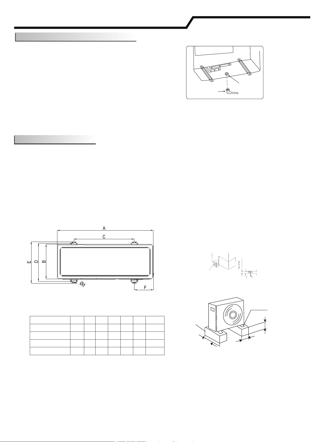
beton
anchor bolt
(Unit:mm)
Model
A
B
C
D
E
F
d
18K
810
280
510
310
338
150
11X17
24K
860
310
542
341
368
168
11X17
36K
900
340
608
368
398
146
10×20
42K/48K
900
320
535
357
385
195
12×20
Concrete base or alike
Min.10cm
Setscrew
(at least 4)
About 40cm
About 10cm
Fig.1
Fig.2
Fig.3
Drainage Elbow and Drain Hose Installation
Outdoor Unit Installation
Drain hose
Drainage elbow
Installation Instructions
Install Drainage Elbow and Drain Hose
·The condensate water may drain from the outdoor unit
when the unit operates in heating mode. In order to avoid
disturbing neighbors and to protect the environment, it is
necessary to install a drainage elbow and a drain hose to
drain out the condensate water.
·Please do the drainage work before the indoor unit and
outdoor unit are connected. Otherwise, it will be difficult to
install drainage elbow after the machine becomes
immovable.)
Connect the drain hose· [field-supplied, inside diameter:
5/8 in. (15mm)] as shown in the figure for drainage.
Note:
Do not use the drainage elbow in the cold region.
Drain may freeze.
(1) Use the washers to fasten the machine at the foundation bolts.
(2) When fastening the outdoor unit with the foundation bolts, the fasten holes position as the Fig.1.
(3) Fasten the outdoor unit as the Fig.2.
(4) Make sure to fasten the outdoor unit tight and level to prevent noise from occurring.
(5) Do not drain off water to the public places to hazardous slips/falls.
(6) The strong base (made of concrete, etc.) should be made. The appliance should be placed not less than
4in. (10cm) high to avoid being wet or corroded. Otherwise, it may cause damage to the appliance or reduce its
life time. (Fig.3)
Do not use bolts that are too
long, or it will be troublesome
of the moving in the future.

Installation Instructions
12
The shorter the refrigerant piping length is, the better. So the connecting pipe should be as short as possible.
1. Piping Requirement
2. Piping Material
(1) Prepare locally-supplied copper pipes.
(2) Select clean copper pipes. Make sure there is no dust and moisture inside the pipes. Blow the inside of the
pipes with nitrogen or dry air, to remove any dust or foreign materials before connecting pipes.
Additional Refrigerant Charge
The unit has been filled with refrigerant.
The outdoor unit is pre-charged with refrigerant to accommodate a total piping length of 5m.
Additional refrigerant (R32) is required for extending the piping beyond 5m:
For 18K: Additional refrigerant charge =(L-5)×15g/m
For 24K/36K/42K/48K: Additional refrigerant charge =(L-5)×35g/m
Refrigerant Piping
Model
Outer Diameter of Pipe (mm)
Gas
Liquid
18K
Φ12.7
Φ6.35
24K/36K/42K/48K
Φ15.88
Φ9.52
Pipe length L
Height difference H
Indoor unit
Outdoor unit
(3)Piping thickness and material are shown as below.
Model
Min. Pipe
length (L)
Max. Pipe
length (L)
Max. Height
difference (H)
18K/24K
3(m)
30(m)
20(m)
36K/42K/48K
3(m)
50(m)
30(m)
15.88
1.0
1.0
19.05
0.8
0.8
0.8
12.7
9.526.35
Diameter
Thickness
(mm)
1.0
22.22

13
3.Processing of Refrigerant Piping
(1) Pipe cutting
Cut the copper pipe correctly with a pipe cutter.
(2) Burrs removal
Completely remove all burrs from the cross section of the pipe.
Put the end of the copper pipe downward to prevent burrs from
dropping in the pipe.
(3) Putting nut on
Remove flare nuts attached to indoor and outdoor units, then put
them on the pipe, burrs of which have been removed.
(Not possible to put them on after flaring work).
Flare nut for pipe depends on the diameter of pipe.
(4) Flaring work
Perform flaring work with a flaring tool as shown below.
(5) Check
Compare the flared work with the figure below.
If flare is noted to be defective, cut off the flared section and perform flaring work again.
When installing pipe through
the wall, secure a cap at the
end of the pipe.
Correct
CorrectIncorrect Incorrect
Correct Incorrect
HoleHole
Attach a cap
or vinyl tape.
Attach a cap
or vinyl tape.
Attach a cap
or vinyl bag with
rubber band.
Do not place the pipe
directly on the ground.
Rain water can
enter.
Diameter
Tilted Uneven Burred
Not good
Good
o
90
Burr
Copper pipe
Spare
reamer
Pipe cutter
Flare nut
Copper pipe
Flaring tool
Clutch type
Wing nut type
Die
Copper pipe
Flare nut
Copper pipe
Die
York
Smooth all around
Inside is shiny without any scratches
Double Spanner Work
Tightening Torque for Flare Nut
15.88
19.05*
*: Perform the flaring work with
type O material.
24.0
19.7
Installation Instructions
(Unit: mm)
!
CAUTION
12.7
9.52
6.35
9.1
13.2
16.6
φ6.35
φ9.52
φ12.7
φ15.88
φ19.05
Tube size (mm)
100
80
60
40
20
Torque N·m ( )
4. Piping connection
(1) Confirm that the valve is closed.
(2) Connect the indoor unit and the outdoor unit with field-supplied
refrigerant piping. Suspend the refrigerant piping at certain points
and prevent the refrigerant piping from touching the weak part of
the building such as wall, ceiling, etc.
(If touched, abnormal sound may occur due to the vibration of the
piping. Pay special attention in case of short piping length.)
(3) Tighten the flare nut with two spanners (one being a torque
wrench) as shown in the right figure.
(4) Apply the refrigerant oil (field-supplied) thinly at the seat surface of
the flare nut and pipe before connecting and tightening.
And when tightening the flare nut, use two spanners.
(5) Outdoor refrigerant piping should connect with stop valve.
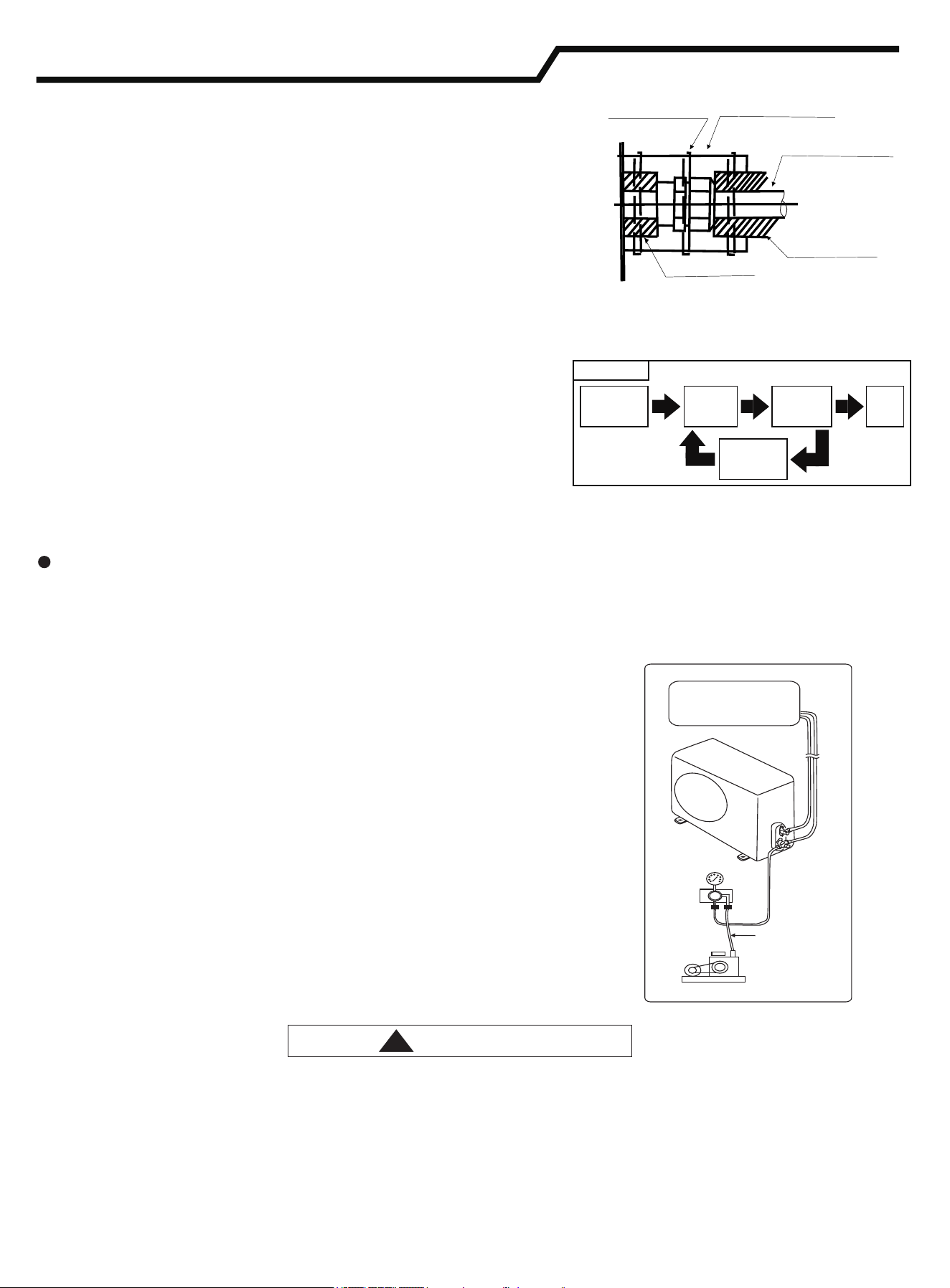
14
Vacuum pumping
-Do use Nitrogen.
Air tight procedure
Completion
of Ref.
Piping
Repairing
of Leakage
Part
Check of
Pressure
Decrease
Applying
Nitrogen
Gas
Pass
Procedure
Charge hose
(for R32)
Piping insulation procedure
Insulation
( )field-supplied
Clamp(field-supplied)
Insulation (field-supplied)
Refrigerant pipe
(field-supplied)
Indoor unit
Outdoor unit
Manifold
valve
Pressure
gauge
Vacuum
pump
Fig.9.2
Installation Instructions
6. Vacuum Pumping and Refrigerant Charge
!
CAUTION
Insulation
(field-supplied)
(6) After finishing connecting the refrigerant pipes, insulate with
proper insulation.
·For outside unit, insulate both pipes.
·Cover piping joints with pipe cover.
·Using piping tape, apply taping starting from the entry of outdoor unit.
- Fix the end of piping tape with adhesive tape.
- When piping has to be arranged through above ceiling, closet
or area where temperature and humidity are high, install
additional sold insulation for prevention of condensation.
5. Air tight test
Connect the gauge manifold using charging hoses with a nitrogen
cylinder to the check joints of the liquid line and the gas line stop
valves.
Perform pressure test.
Don't open the gas line stop valves.
Apply nitrogen gas pressure of 550 psig (3.8 MPa).
Check for any gas leakage at the flare nut connections, or brazed
parts by gas leak detector or foaming agent.
Gas pressure doesn’t decrease, which is OK.
After the air tight test, release nitrogen gas.
(1) Remove the service port cap of the stop valve on the gas pipe
side of the outdoor unit.
(2) Connect the manifold gauge and vacuum pump to the service port
of the stop valve on the gas pipe side of the outdoor unit.
(3) Run the vacuum pump. (Work for more than 15 minutes.)
(4) Check the vacuum with the gauge manifold valve, then close the
gauge manifold valve and stop the vacuum pump.
(5) Leave it as is for one or two minutes. Make sure that the pointer of
the manifold gauge remains in the same position. Confirm that the
pressure gauge shows -14.7psig (-0.101MPa or -760mmHg).
(6) Remove the manifold gauge quickly from the service port of the
stop valve.
(7) After refrigerant pipes are connected and evacuated, fully open
all stop valves on both sides of gas pipe and liquid pipe.
(8) Open adjusted valve to add refrigerant (the refrigerant is liquid).
(9) Tighten the cap to the service port .
(10) Retighten the cap.
(11) Leak test foam with halogen leak detector to check the flare nut
and brazing for leaks. Use foam that does not generate
ammonia (NH3) in the reaction.
·An excess or a shortage of refrigerant is the main cause of trouble to the unit. Charge the correct quantity of
refrigerant according to the description in the manual.
·Check for refrigerant leaks. If a large refrigerant leakage occurs, it will cause difficulty in breathing or
harmful gases would occur if there is an open flame in the room.
15
!
危 险
!
●With tape material along the wire wrapped, sealed wiring holes, prevent the condensed water leaks and insects.
●Tightly secure the power source wiring by using the cord clamp inside the unit.
General Check
(1) Make sure that the field-selected electrical components (main power switches, circuit breakers, wires, conduit connectors
and wire terminals) have been properly selected according to the electrical data.
Make sure that the components comply with National Electrical Code (NEC).
(2) Check to ensure that the voltage of power supply is within 10% of nominal voltage and earth phase is contained in the
power supply wires. If not, electrical parts will be damaged.
(3) Check to ensure that the capacity of power supply is enough.
If not, the compressor will not be able to operate because of abnormal voltage drop at starting.
(4) Check to ensure that the earth wire is connected.
(5) Install a main switch, multi-pole main switch with a space of 3.5mm or more, single phase main switch with a space of
3.0mm or more between phases.
(6) Check to ensure that the electrical resistance is more than 2MΩ, by measuring the resistance between ground and the
terminal of the electrical parts. If not, do not operate the system until the electrical leakage is found and repaired.
WARNING
CAUTION
Additional refrigerant charge
The unit has been filled with refrigerant.
Please calculate additional charge according to “Piping Requirement”.
After finishing vacuum pump procedures, first exhaust air from the charge hose, then open valves, charge refrigerant
through liquid stop valve.
In the end, please close valves and record the refrigerant charge quantity.
Wiring
Installation Instructions
NOTE: Fix the rubber bushings with adhesive when conduit tubes to the outdoor unit are not used.
·Turn OFF the main power switch of the indoor unit and the outdoor unit and wait for more than 3 minutes before
.electrical wiring work or a periodical check is performed
·Check to ensure that the indoor fan and the outdoor fan have stopped before electrical wiring work or a periodical
check is performed.
·Protect the wires electrical parts etc from rats or other small animals If not protected rats may gnaw at , , . . ,
unprotected parts and at the worst a fire will occur , .
·Avoid the wiring from touching the refrigerant pipes plate edges and electrical parts inside the unit , .
, .If so, the wires will be damaged and at the worst a fire will occur
·Install an ELB (Electric Leakage Breaker) in the power source .
, .If ELB is not used it will cause electric shock or fire at the worst
, ·This unit uses an inverter which means that it must be used with an earth leak detector capable of handling
harmonics in order to prevent malfunctioning of the earth leak detector itself.
·Do not use intermediate connection wires, stranded wires(see “Attentions when Connecting the Power Supply
Wiring”, extension cables or control line connection, because the use of these wires may cause heating, electric
shock or fire.
.·The tightening torque of each screw is shown as follows
: . · . . . ·M4 0.7 to 1 0 lbf ft (1 0 to 1 3 N m)
M5 1.5 to 1.8 lbf ft (2 0 to 2 5 N m): · . . . ·
M6 3.0 to 3.7 lbf ft (4 0 to 5 0 N m): · . . . ·
M8 6.6 to 8.1 lbf ft (9 0 to 11 0 N m): · . . . ·
M10 13.3 to 17.0 lbf ft (18 0 to 23 0 N m): · . . . ·
Keep the above tightening torque during wiring work .

NOTE:
(1) Follow local codes and regulations when selecting field wires, and all the above are of the minimum wire size.
(2) Use the wires which are not lighter than the ordinary polychloroprene sheathed flexible cord. (Cord designation H07RN-F).
(3) The wire sizes marked with *1 in the above table are selected at the maximum current of the unit according to
IEC60335-1,or regional standards.
(4) When the transmitting cable is longer than 15 meters, a larger wire size should be selected.
(5) Install main switch and ELB (if required by local codes) for each system separately. Select the high response type ELB that
is acted within 0.1second. For recommended capacity, see outdoor machine switch capacity.
Max. Running Current (A): REFER TO NAMEPLATE
1.When connecting the terminal block using stranded wire, make
sure to use the round crimp-style terminal for connection to the
power supply terminal block. Place the round crimp-style
terminals on the wires up to the covered part and secure in place.
2. When connecting the terminal block using a single core wire, be
sure to perform curving.
<Attentions when Connect the power supply wiring>
Terminal
Stranded wire
Single core wire
covered part
Round crimp-style terminal
Electrical data
Installation Instructions
16
Current i(A)
2
Wire Size(mm )
i≤6 0.75
6<i≤10 1
10<i≤16 1.5
16<i≤25 2.5
25<i≤32 4
32<i≤40 6
40<i≤63 10
63<i
*
Selection According to IEC60335-1
(6) In the case that power cables are connected in series, add each unit maximum current and select wires as below.
* In the case that current exceeds 63A, do not connect cables in series.
Model
Capacity
Power Supply
ELB
Power Source
Cable Size
Transmitting
Cable Size
Circuit
Breaker
(A)
Nominal
Current
(A)
Nominal Sensitive
Current
(mA)
IEC60335-1*1
IEC60335-1*1
18K
220-240V~/50Hz
20
30
3×1.5mm²
4×1.5mm²
20
24K/36K
32
30
3×2.5mm²
4×1.5mm²
32
42K/48K
40
30
3×4.0mm²
4×1.5mm²
40
220-240V~/50Hz
220-240V~/50Hz
DRED (Demand Respond Enable System) Connector
A demand communication cable is supplied with outdoor unit.
It can be conne to DRED r limit setting of power consumption if need.

17
Installation Instructions
Trial Run
Make sure that turn on electric power 6 hours before operating the unit.
Trial run should be performed after refrigerant piping, condensate draining, wiring, etc. have been finished.
Do not operate the system until all the check points have been cleared.
(A) Check to ensure that the stop valves of the outdoor unit are fully opened.
(B) Check to ensure the electric wires has been fully connected.
(C) Check to ensure that the electrical resistance is more than 2MΩ, by measuring the resistance between ground
and the terminal of the electrical parts. If not, do not operate the system until the electrical leakage is found and
repaired.
·Turn off the power after trial run is finished.
Installation of the appliance is generally finished after the above operations are done. If you still have any trouble,
please contact local technical service center of our company for further information.
Trial run function identification
Operate remote controller turn ON, then proceed trial run.
Pay attention to the following items while the system is running.
Do not touch any of the parts by hand at the discharge gas side, since the compressor chamber and the pipes at
the discharge side are heated higher than 90℃.

Version No.2300054,C