不属于印刷内容印刷
规格:A5
材质:80g双胶
封面用彩色,
内页黑白

Please read this manual carefully before using, and keep it for future reference.
User Manual
BRGC6001SS - 60 cm 4 burner gas stainless steel cooktop
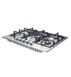
BRGC9001SS - 90 cm 5 burner gas stainless steel cooktop
BRGC6001BLK - 60 cm 4 burner gas glass cooktop
BRGC9001BLK - 90 cm 5 burner gas glass cooktop
BRGC3001BLK - 30 cm single burner gas glass hob
BRGC6040DSS - 60 cm 4 burner gas stainless steel hob
BRG7000SS - 70 cm 5 burner gas stainless steel hob
BRG7000BLK - 70 cm 5 burner gas glass cooktop
BRGC7001SS - 70 cm 5 burner gas stainless steel hob

P a g e | 2
CONTENTS
1 PACKAGE....................................................................................................................................................................................3
1.1 IMPORTANT - CHECK FOR ANY DAMAGE OR MARKS
.........................................................................................3
1.2 HANDLING
....................................................................................................................................................................... 3
1.3 BEFORE USING YOUR NEW GAS HOB
.......................................................................................................................3
2 SAFETY WARNINGS....................................................................................................................................................................4
2.1 IMPORTANT INFORMATION
......................................................................................................................................... 4
2.2 GENERAL INFORMATION
............................................................................................................................................. 4
2.3 CHILD SAFETY.................................................................................................................................................................. 5
2.4 GENERAL SAFETY............................................................................................................................................................5
2.5 DURING USE.....................................................................................................................................................................5
2.6 CLEANING
........................................................................................................................................................................5
2.7 INSTALLATION..................................................................................................................................................................6
3 SPECIFICATIONS.........................................................................................................................................................................7
3.1
BRGC3001BLK.................................................................................................................................................................7
3.3 BRG7000SS/BRG7000BLK/BRGC7001SS
............................................................................................................. 9
3.5 BRGC9001BLK..............................................................................................................................................................11
3.6 BRGC9001SS..............................................................................................................................................................12
3.7 ELECTRICAL DETAILS....................................................................................................................................................13
GAS DETAILS
.......................................................................................................................................................................... 13
4 USING THE GAS HOB
.............................................................................................................................................................. 14
4.1 BEFORE FIRST USE......................................................................................................................................................... 14
4.2 SWITCHING THE HOB ON...........................................................................................................................................14
4.3 AUTOMATIC IGNITION WITH FLAME FAILURE SAFETY DEVICE
...........................................................................15
4.4 ENERGY SAVING TIPS..................................................................................................................................................15
5 CLEANING
.................................................................................................................................................................................16
5.1 CLEANING THE HOB TOP........................................................................................................................................... 16
5.2 AFTER EACH USE
.......................................................................................................................................................... 16
5.3 CLEANING THE HOB BURNERS
..................................................................................................................................17
5.4 MAINTAINING THE CAST IRON PAN STANDS........................................................................................................ 18
6 INSTALLATION AND GAS CONNECTION
...........................................................................................................................19
6.1 LEGAL..............................................................................................................................................................................19
6.2 POSITIONING
.................................................................................................................................................................19
6.3 ALL MODELS..................................................................................................................................................................19
6.4 IMPORTANT INFORMATION.......................................................................................................................................20
6.5 VENTILATION REQUIREMENTS
................................................................................................................................... 20
6.6 DUAL GAS REGULATOR VALVE INTRODUCTION.................................................................................................21
6.7 The gas kinds of conversion method:................................................................................................................... 22
6.8 GAS SAFETY (INSTALLATION AND USE) REGULATIONS.......................................................................................23
INSTALLATION PROCESS
.......................................................................................................................................................24
6.9 GAS ADJUSTMENT (CONVERSION TO LPG)......................................................................................................... 24
6.10 MINIMUM FLOW ADJUSTMENT FOR HOB GAS TAPS........................................................................................ 25
6.11 GAS TAP MAINTENANCE
......................................................................................................................................... 26
6.12 ELECTRICAL CONNECTION
.....................................................................................................................................27
6.13 REPLACING THE MAINS SUPPLY CABLE............................................................................................................... 28
6.14 INSTALLATION SUMMARY WARNINGS................................................................................................................. 29
7 DISPOSAL
...................................................................................................................................................................................30
8 CUSTOMER CARE.................................................................................................................................................................... 31
3.2
BRGC6040DSS ............................................................................................................................................................... 8
3.4
BRGC6001SS /RGC6001BLK......................................................................................................................................10
web:brohn.com.au
P a g e | 3
1 PACKAGE
1.1 IMPORTANT - CHECK FOR ANY DAMAGE OR MARKS
Please thoroughly inspect your goods
at the delivery time
, if you notice any
damage to
your goods:
Please notify the delivery team at the time of delivery and
do NOT
accept damaged product
.
Please notify us immediately as the problem can be solved and damaged
product
can be returned to the courier office.
When package is opened, and damage/marks are found on the appliance, it
must be
reported within 24 hours. Do not install or connect the item and keep
the package as it
was originally if you wish to claim for damage/marks under
the manufacturer’s warranty.
This does not affect your statutory rights.
Evidence of damage will be required.
1.2 HANDLING
Do not use cable to carry or move the appliance.
Carry out the movements and transportation in the original packaging.
Pay maximum attention to the appliance while loading/unloading and
handling.
Ensure that the packaging is securely closed during handling and
transportation.
Protect from external factors (such as humidity, water, etc.) that may
damage the
packaging.
Take caution while handling and transporting appliance to prevent risk
of poor operation due to possibility of bumps, crashes, drops, etc.
1.3 BEFORE USING YOUR NEW GAS HOB
Read this guide, taking special note of the ‘Safety Warnings’ section.
Remove any protective film that may still be on your gas hob.
web:brohn.com.au
P a g e | 4
2 SAFETY WARNINGS
2.1 IMPORTANT INFORMATION
Your safety is of the utmost importance to us. Please make sure
that you read this instruction booklet before attempting to
install or use the
appliance. If you are unsure of any of the information contained
in this
booklet, please contact customer support or the
retailer where you purchased the product.
2.2 GENERAL INFORMATION
This appliance is designed for domestic household use.
The adjacent furniture and all materials used in the installation must be
able to
withstand a minimum temperature of 85°C above the ambient
temperature of the
room it is located in whilst the cooktop is in use.
Certain types of vinyl or laminate kitchen furniture are particularly prone
to heat
damage or discoloration at temperatures below the guidelines
given above.
Any damage caused by the appliance being installed in
contravention of this
temperature limit will be the liability of the owner.
You should not use this appliance to store items on or as a work surface.
No modifications to the appliance are permitted.
You should not store or place flammable liquids/materials on top or
near the
appliance. Items made of aluminium, plastic or plastic film
should also be kept
away from the appliance as they may fuse to the
surface.
Repairs may only be carried out by authorised service agents and
licensed
professionals.
web:brohn.com.au

P a g e | 5
2.3 CHILD SAFETY
It is strongly recommended that the appliance is not to be used by
children or
persons with reduced physical, sensory or mental
capabilities, or lack of
experience/knowledge without appropriate
supervision.
Ensure child supervision to prevent play with the appliance.
2.4 GENERAL SAFETY
The appliance should only be installed and connected by licensed
qualified professionals.
Care should be taken to ensure that the units and work surfaces that you
build the
appliance into meets with the relevant standards.
2.5 DURING USE
Care should be taken when utilising the appliance to reduce risk of possible
burns.
You should not allow the electrical connection cables to come into
contact with
the hob surface when it is hot or any hot cookware.
If fat and oil overheat, it can ignite extremely quickly. For this reason, when
cooking
with fat and oil, the appliance should not be left unattended.
Make sure that all of the cooking zones are switched off after use.
2.6 CLEANING
Cleaning of the hob should be carried out on a regular basis.
IMPORTANT: Before attempting to clean the appliance, it should
be
disconnected from the mains and cool down.
Great care should be taken whilst using this appliance and when
following the
cleaning procedure.
You should not use a steam jet or any other high pressure cleaning
equipment to
clean the appliance.
web:brohn.com.au

P a g e | 6
2.7 INSTALLATION
This appliance must be correctly installed by a qualified individuals and connected to
the gas supply by licensed professionals strictly in accordance with the
manufacturer’s instructions, local standards and regulations.
Manufacturer or a retailer of the appliance declines any responsibility for injury or
damage, to person or property, as a result of improper use or installation of this
appliance.
web:brohn.com.au
P a g e | 7
3 SPECIFICATIONS
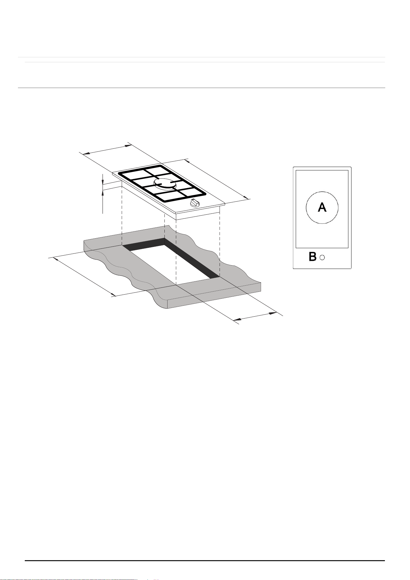
3.1 BRGC3001BLK
Product specifications:
A = 1 x 14.4 MJ/h triple crown (wok) burner (NG)
B = Control panel
Front control operation
Automatic ignition
Metal pan stands
Flame failure safety device on each burner.
300
520
40
490
268
web:brohn.com.au
P a g e | 8
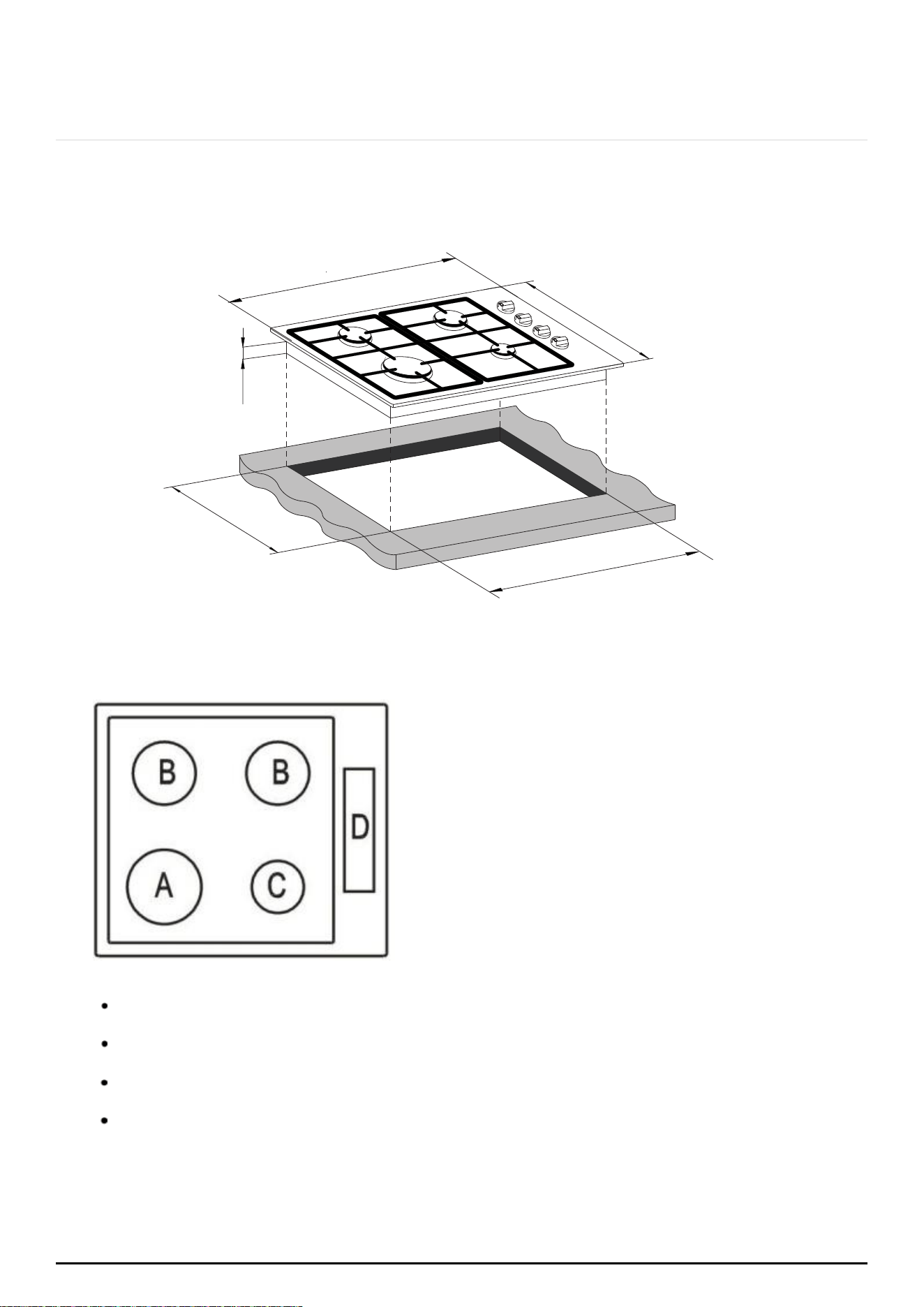
3.2 BRGC6040DSS
Side control operation
Automatic ignition
Product specifications:
A = 1 x 10.8 MJ/h rapid burner (NG)
B = 2 x 6.5 MJ/h semi-rapid burners(NG)
C = 1 x 3.6 MJ/h auxiliary burner (NG)
D = Control panel
Metal pan stands
Flame failure safety device on each burner
40
580
500
480
560
web:brohn.com.au
P a g e | 9
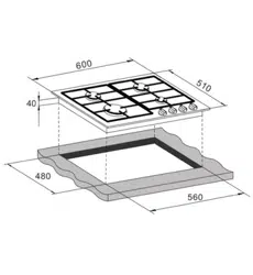
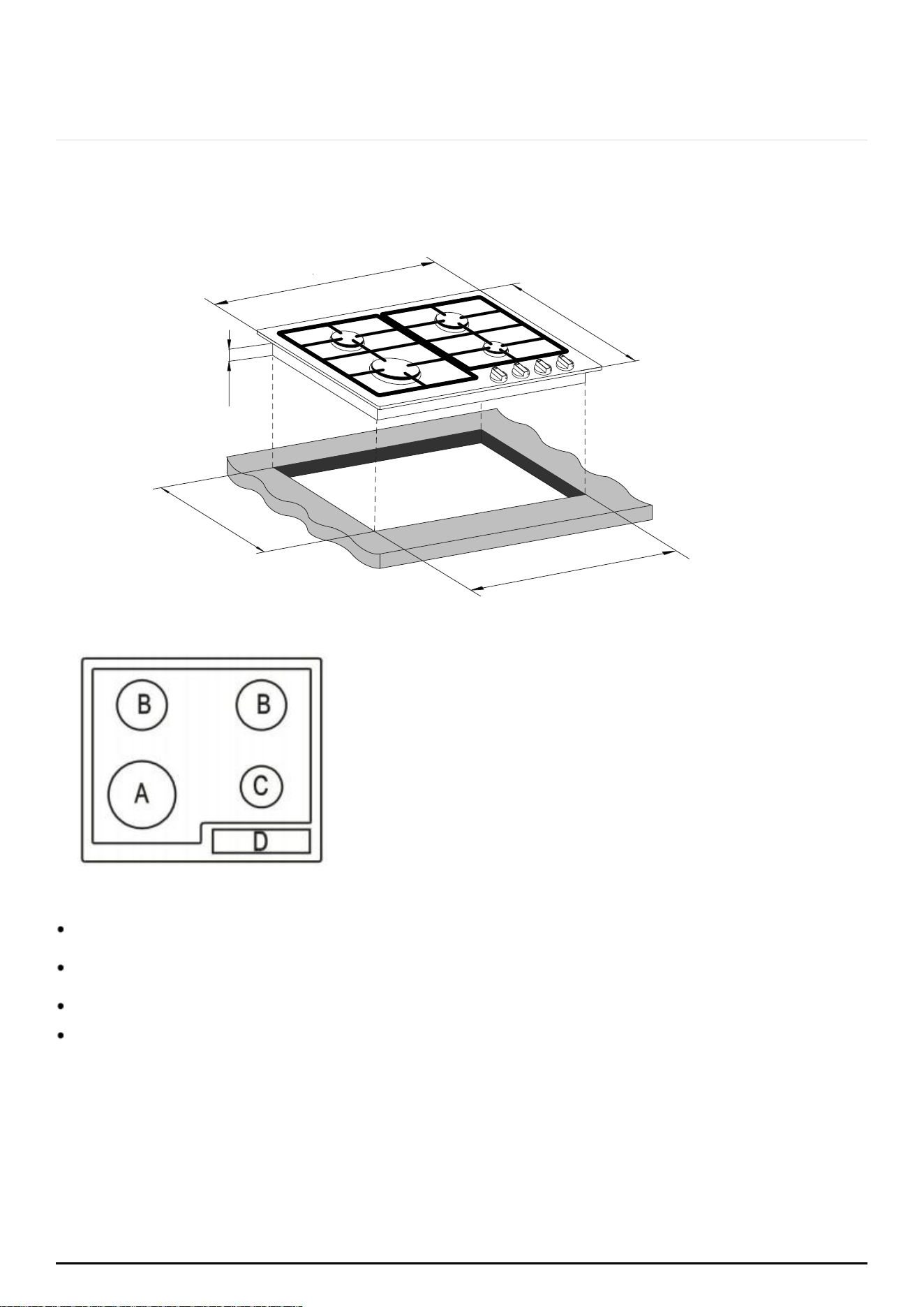
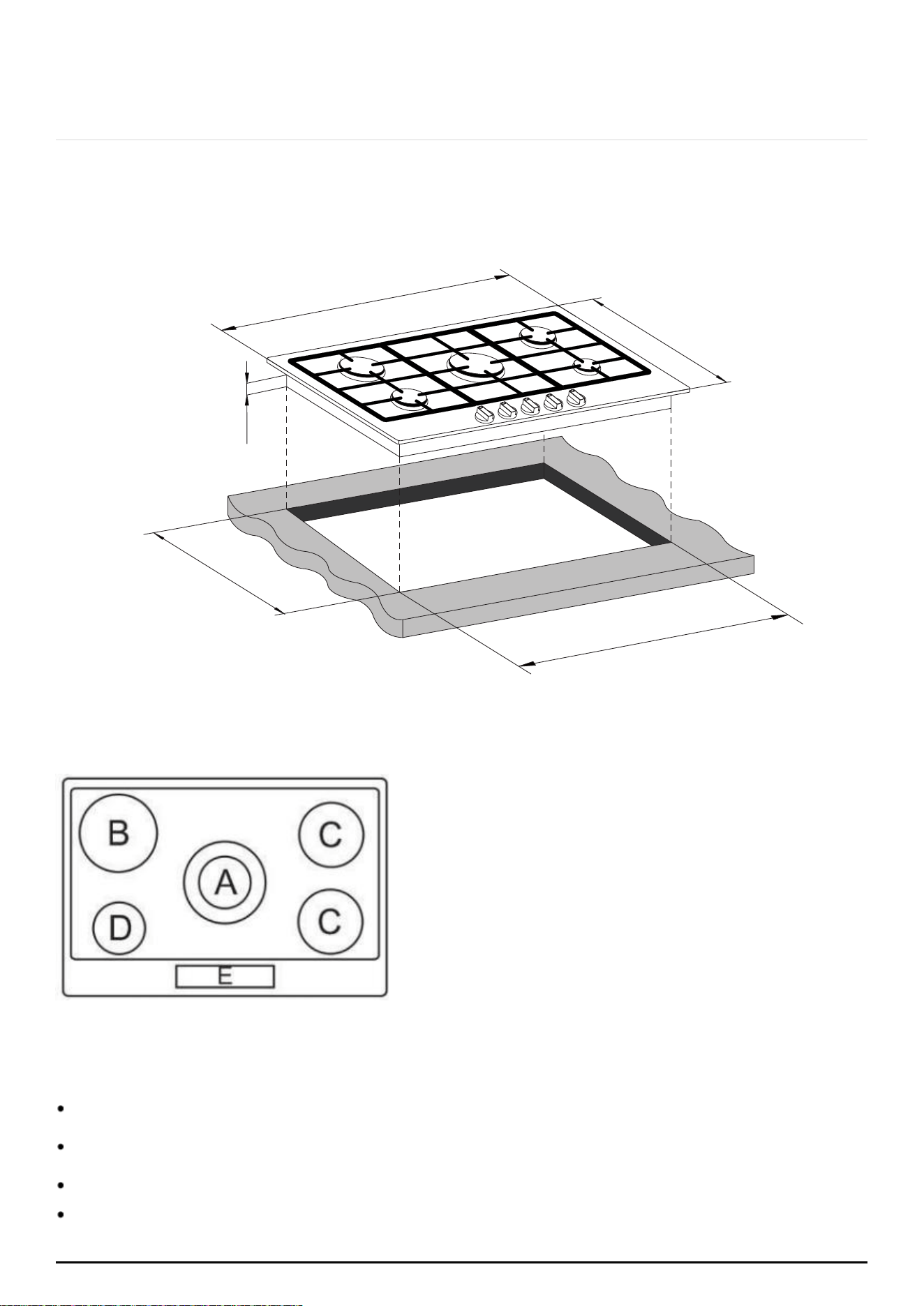
3.3 BRGC6001SS/BRGC6001BLK
Product specifications:
A = 1 x 14.4 MJ/h triple crown (wok) burner (NG)
B = 2 x 6.5 MJ/h semi-rapid burners (NG)
C = 1 x 3.6 MJ/h auxiliary burner (NG)
D = Control panel
Front control operation
Automatic ignition
Heavy duty metal pan stands
Flame failure safety device on each burner
600
510
480
560
web:brohn.com.au
P a g e | 10
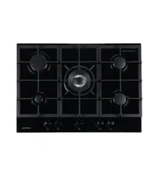
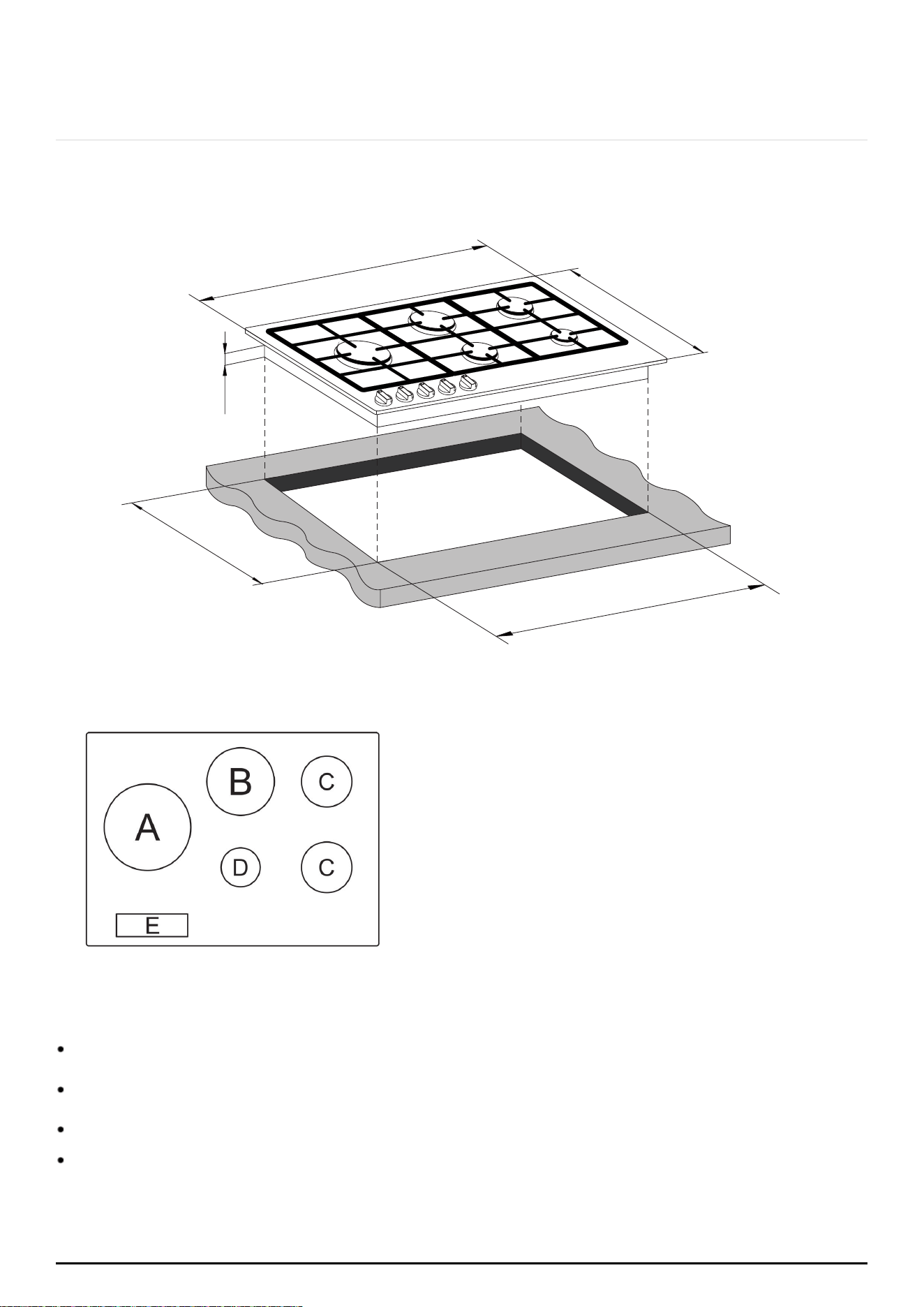
3.6 BRGC7001SS/BRG7000SS/BRG7000BLK
Product specifications:
A = 1 x 14.4 MJ/h triple crown (wok) burner(NG)
B = 1 x 10.8 MJ/h rapid burner (NG)
C = 2 x 6.5 MJ/h semi-rapid burners(NG)
D = 1 x 3.6 MJ/h auxiliary burner(NG)
E = Control panel
Front control operation
Automatic ignition
Heavy duty metal pan stands
Flame failure safety device on each burner
700
510
40
480
560
web:brohn.com.au
P a g e | 11
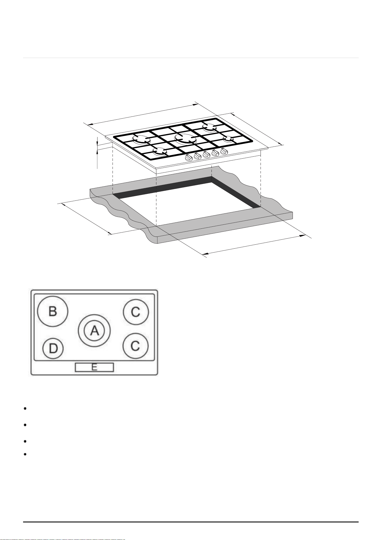
3.7 BRGC9001BLK
Front control operation
Automatic ignition
Heavy duty metal pan stands
Flame failure safety device on each burner
Product specifications:
A = 1 x 14.4 MJ/h triple crown (wok) burner (NG)
B = 1 x 10.8 MJ/h rapid burner (NG)
C = 2 x 6.5 MJ/h semi-rapid burners(NG)
D = 1 x 3.6 MJ/h auxiliary burner (NG)
E = Control panel
860
510
40
480
830
web:brohn.com.au
P a g e | 12
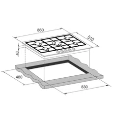
3.8 BRGC9001SS
Front control operation
Automatic ignition
Heavy duty metal pan stands
Flame failure safety device on each burner
860
510
40
480
830
Product specifications:
A = 1 x 14.4 MJ/h triple crown (wok) burner (NG)
B = 1 x 10.8 MJ/h rapid burner (NG)
C = 2 x 6.5 MJ/h semi-rapid burners(NG)
D = 1 x 3.6 MJ/h auxiliary burner(NG)
E = Control panel
web:brohn.com.au

P a g e | 13
3.9 ELECTRICAL DETAILS
Rated Voltage:
Supply
Connection:
Max
Rated Inputs:
Mains Supply Lead:
220 - 240 Vac 50 / 60 Hz
3A
0.0008 kW
3 core x 0.75mm² (Type RR-F <HAR> marked)
GAS DETAILS
Connection:
Type:
Rp ½ (ISO R7)
Natural Gas (1.0 KPa) LPG (2.75KPa)
web:brohn.com.au
P a g e | 14
4 USING THE GAS HOB
4.1 BEFORE FIRST USE
IMPORTANT: Any film or stickers that are present on the cooktop surface
should be removed before use.
The cooktop surface should be cleaned regularly (see “Care and Maintenance”
section).
4.2 SWITCHING THE HOB ON
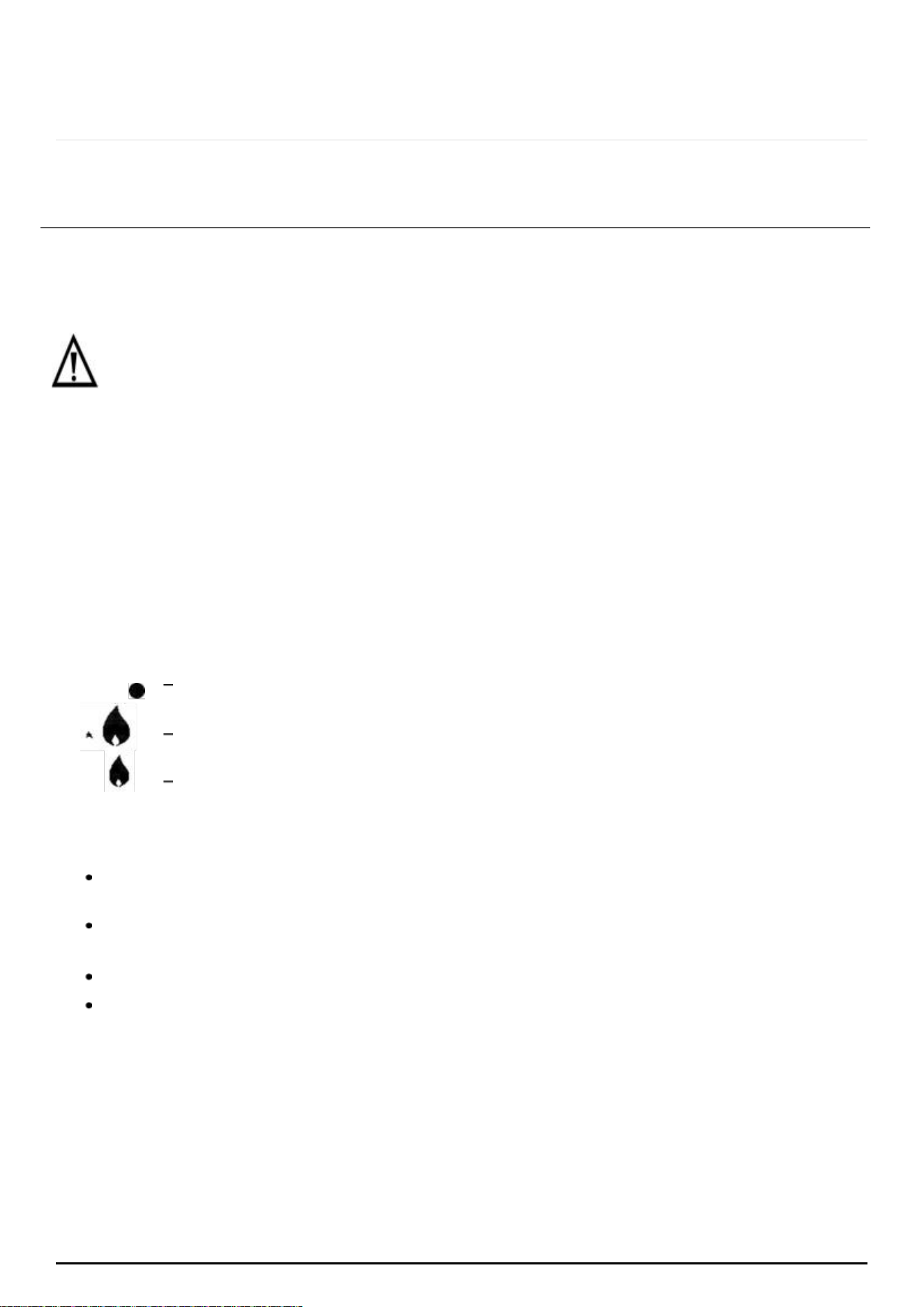
The following symbols will appear on the control panel next to each control knob:
Gas off
Large flame: maximum setting
Small flame: minimum setting
The minimum setting is at the end of the anti-clockwise rotation of the control
knob.
All operation positions must be selected between the maximum and
minimum position.
Never select a knob position between the maximum and off position.
The symbol on the control panel, next to the control knob will indicate
which gas burner it operates.
web:brohn.com.au
P a g e | 15
4.3 AUTOMATIC IGNITION WITH FLAME FAILURE SAFETY DEVICE
The appliance is fitted with a flame failure safety device on each burner,
which is
designed to stop the flow of gas to the burner head in the event of
the flame going
out.
To ignite a burner:
Press in the control knob of the burner that you wish to light and turn it anti-
clockwise to the maximum position.
If you keep the control knob depressed, the automatic ignition for the
burner will
operate.
You should hold down the control knob for 20 seconds after the flame
on the burner has lit.
After this 20 second interval, turn the control knob to your required setting
between
the maximum and minimum setting symbols.
To switch the burner off, turn the control knob fully clockwise to the
“gas off” position.
In case of power failure, the burners can be lit by carefully using a match.
4.4 ENERGY SAVING TIPS
BURNERS
PANS
Minimum diameter
Maximum diameter
Wok
220 mm
260 mm
Rapid
180 mm
220 mm
Semi-rapid
120 mm
200 mm
Auxiliary
80 mm
160 mm
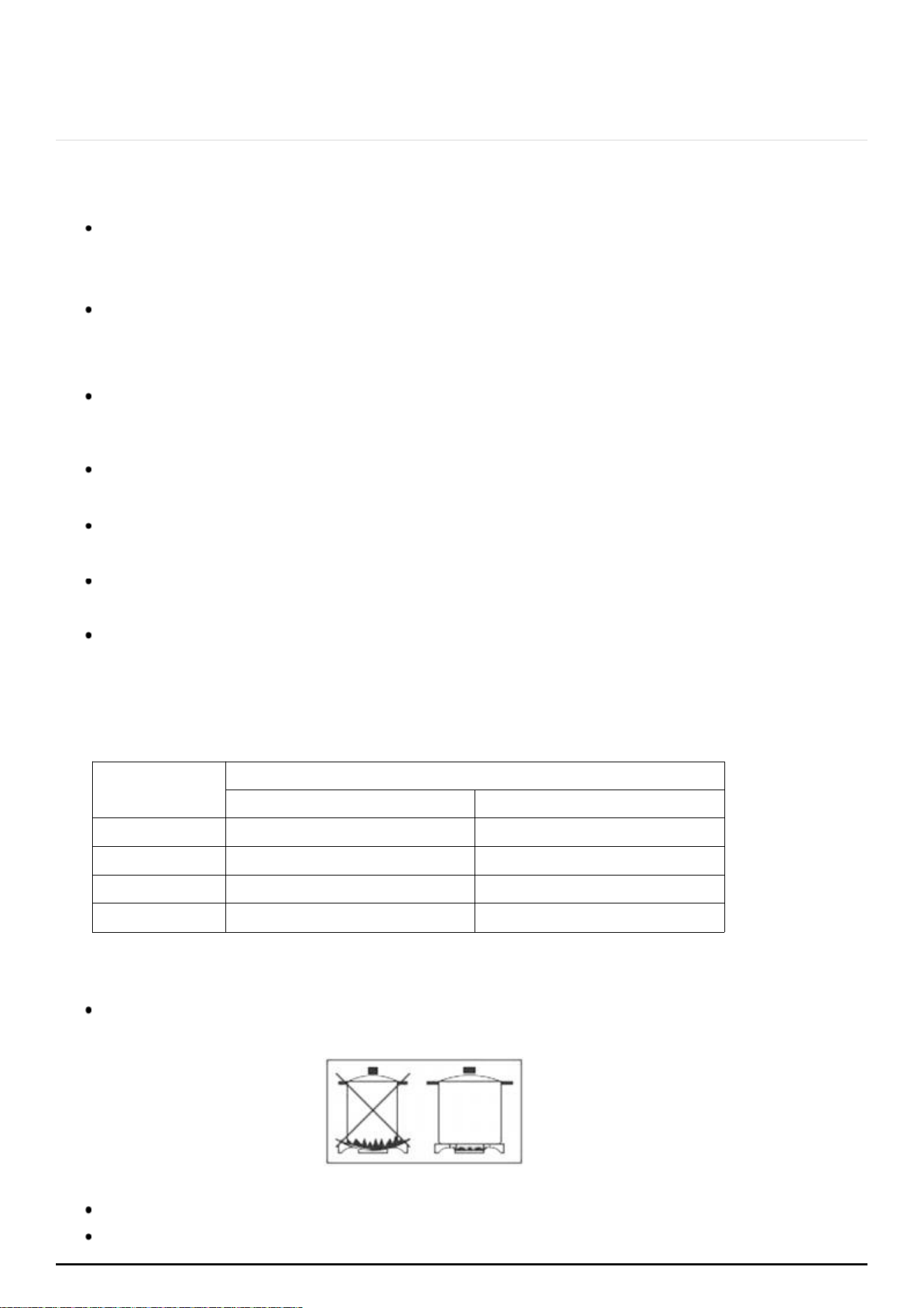
The diameter of the bottom of the pan should be compatible with the
burner.
Use flat bottomed pans only.
The burner flame must never extend beyond the diameter of the pan.
web:brohn.com.au
P a g e | 16
5 CLEANING
Cleaning operations must only be carried out when the hob is cool.
The appliance should be disconnected from your mains supply
before
commencing any cleaning process.
5.1 CLEANING THE HOB TOP
Any residues remaining on the hob top surface from cleaning
agents will
damage it. It is recommended any residues are removed with warm
soapy water.
Abrasive cleaners or sharp objects will damage the hob surface; it
should be
cleaned using warm soapy water.
Although it is easier to clean some deposits whilst the hob surface is still
warm, ensure that the hob surface, pan supports, and hob burners
have all cooled
sufficiently before you attempt to touch them.
5.2 AFTER EACH USE
Remove the pan stands and wipe the appliance over with a soft, damp
cloth that has been in warm soapy water. The cloth should be wrung out
after being taken
out of the soapy water.
Dry the appliance by rubbing the surface with a soft, clean cloth.
We would recommend that an appropriate stainless-steel cleaner and
polish is regularly used on the stainless-steel surfaces of this appliance.
5.3 CLEANING THE HOB BURNERS
The hob burners should be cleaned once a week or more frequently if they get
soiled.
IMPORTANT:
Make sure that the hob surface, pan stands and hob burners have
cooled
before you attempt to touch them.
web:brohn.com.au

P a g e | 17
Remove the hob burners by pulling them upwards and away from the hob
top.
Soak them for about ten minutes in hot water and a small amount of
detergent.
After cleaning and washing them, wipe and dry carefully.
Before placing the burners back on the hob top, make sure that the gas
jet is not
blocked.
IMPORTANT: Make sure that you reassemble the burners in the original way.
5.4 MAINTAINING THE CAST IRON PAN STANDS
IMPORTANT:
Ensure that the hob surface and pan stands have cooled
before you
attempt to touch them.
Wipe the pan stands over with a soft, damp cloth washed into warm soapy
water.
Using a paper towel, thoroughly dry the pan stands.
To maintain the appearance of the cast iron pan stands, it is recommend
that you rub a small amount of olive oil into the pan stands after you have
finished cleaning
them.
web:brohn.com.au
P a g e | 18
6 INSTALLATION AND GAS CONNECTION
6.1 LEGAL
The installation must be carried out by a licensed installer and
professional gas
fitter in accordance with the local standards and
regulations.
6.2 POSITIONING
The adjacent furniture must be able to withstand a minimum
temperature rise
of 85°C above the ambient temperature of the room it
is located in.
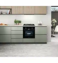
This appliance is designed to be located in a kitchen.
web:brohn.com.au
P a g e | 19
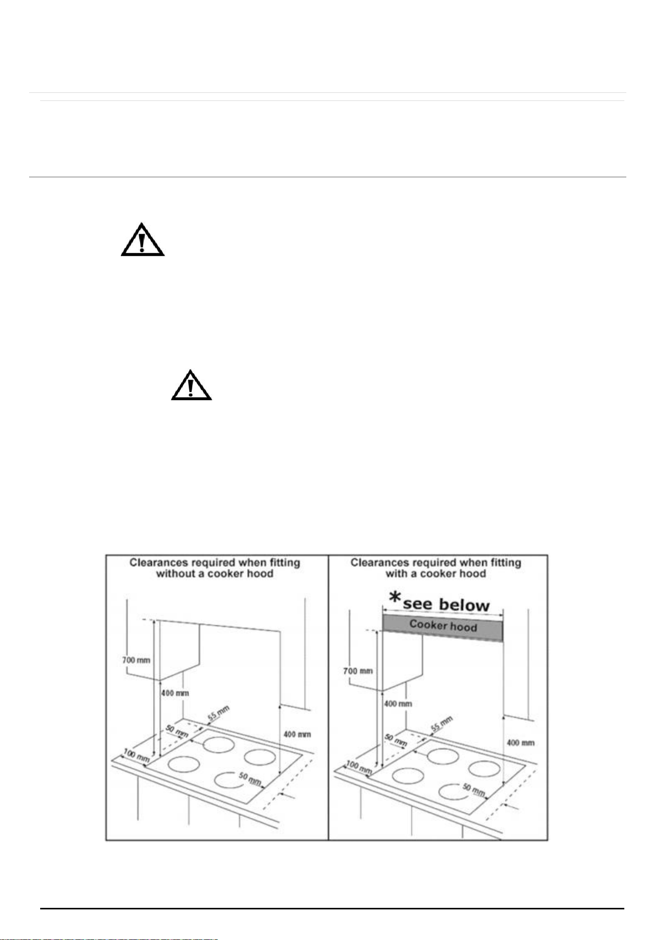
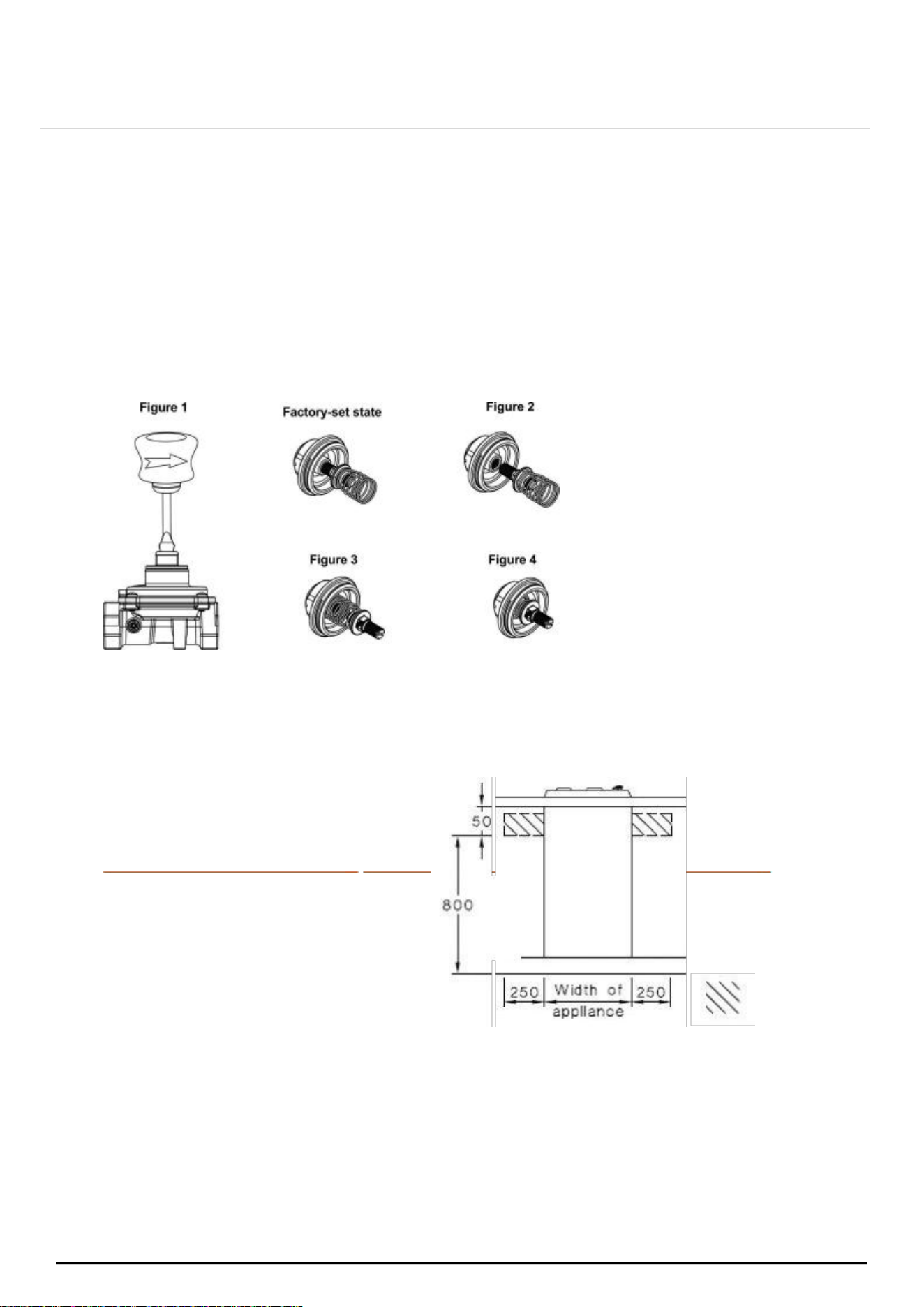
This appliance is classified as Class 3 and therefore is to be built into a
kitchen unit
(depending on size) or 600mm worktop, providing the following
minimum distances are
allowed:
The edges of the hob must be a minimum distance of 55 mm from a side
or rear
wall.
700 mm between the highest point of the hob surface (including the
burners) and
the underside of any horizontal surface directly above it.
400 mm between the hob surface, providing that the underside of the
horizontal surface is in line with the outer edge of the hob. If the
underside of the horizontal surface is lower than 400 mm, then it must be
at least 50 mm away from the outer edges of the hob.
50 mm clearance around the appliance and between the hob
surface and any
combustible materials.
6.3 ALL MODELS
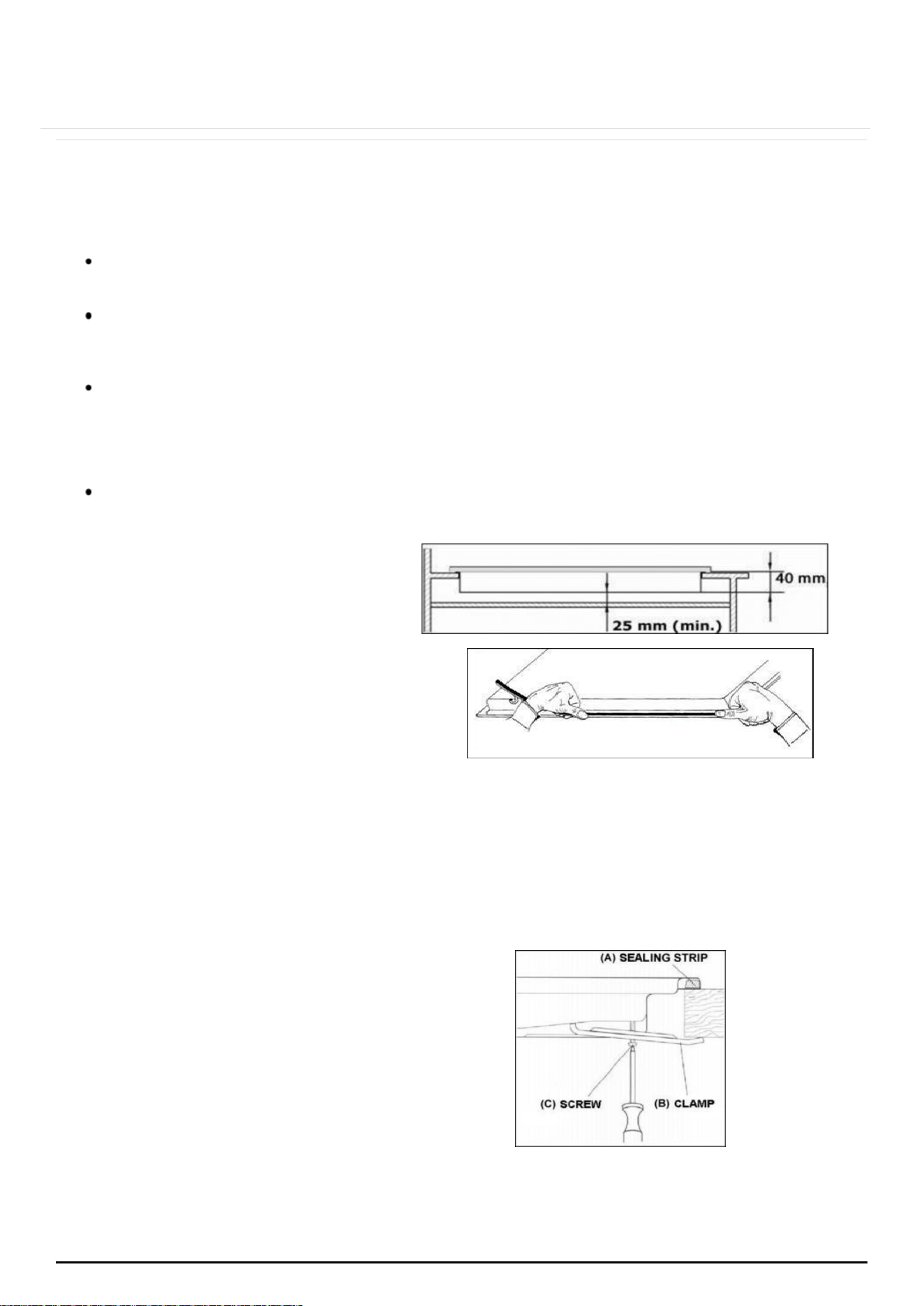
IMPORTANT: You must have a gap of
at least 25 mm between the
underneath of the appliance and any
surface that is below it.
(A) Sealing strip
(B) Clamp
(C) Screw
Carefully turn the hob upside down
and place it on a cushioned mat.
Apply the sealing strip (A) provided
around the edge of the appliance.
The protective covering must be
removed from all sides.
Do not leave gaps in the sealing agent or overlap it creating uneven thickness.
web:brohn.com.au
P a g e | 20
NOTE: It will be difficult to remove the hob from the benchtop (if needed), if
a silicon
sealant has been used to seal the appliance to the benchtop.
Place the clamp
(B)
over the holes that match the size of the screws. There
are one set of screw holes in each corner of the hob. Slightly tighten a screw
(C)
through the
clamp
(B)
so that the clamp is attached to the hob, but so
that you can still adjust
the position of it.
Carefully turn the hob back over and then gently lower it into the aperture
hole that
you have cut out.
On the underneath of the hob, adjust the clamps into a position that is
suitable for your worktop. Then fully tighten the screws (C) to secure the hob
into position.
6.4 IMPORTANT INFORMATION
This hob is supplied to run on natural gas and cannot be used on any other
type of
gas without modification.
Conversion for use on LPG and other gases must only be undertaken by a
licensed professional.
The hob must be installed by a qualified installer.
Failure to install the appliance correctly could invalidate warranty and
lead to prosecution under the local law and regulations.
6.5 VENTILATION REQUIREMENTS
The room containing the hob should have an adequate air ventilation.
The room must have opening windows or equivalent, some rooms may also
require a permanent vent.
If the room has a volume of less than 5m³, it will require an air vent of
100cm² in
effective area.
If the room has a volume between 5 and 10m³, it will require an air vent of
50cm²
unless it has a door opening directly to the outside.
If it is installed in a room with a volume that exceeds 11m³, then no air
vent is
required.
Consideration must be taken if there are any other fuel burning
appliances in the
same room.
Ensure that the room containing the hob is well ventilated. Keep natural
ventilation
holes or install a mechanical ventilation device such as a
rangehood.
web:brohn.com.au
P a g e | 21
Prolonged intensive use of the appliance may call for additional
ventilation, either
by the opening of a window, or by increasing the
level of the mechanical
ventilation device (where present).
This hob is not fitted with a device for discharging the products of
combustion.
Ensure that the ventilation rules and regulations are followed.
The walls behind and near the hob should be resistant to heat,
steam and
condensation.
Remember that the quantity of air necessary for combustion must never
be less
than 2m³/h for each kW of power (see total power in kW on the
appliance rating
plate).
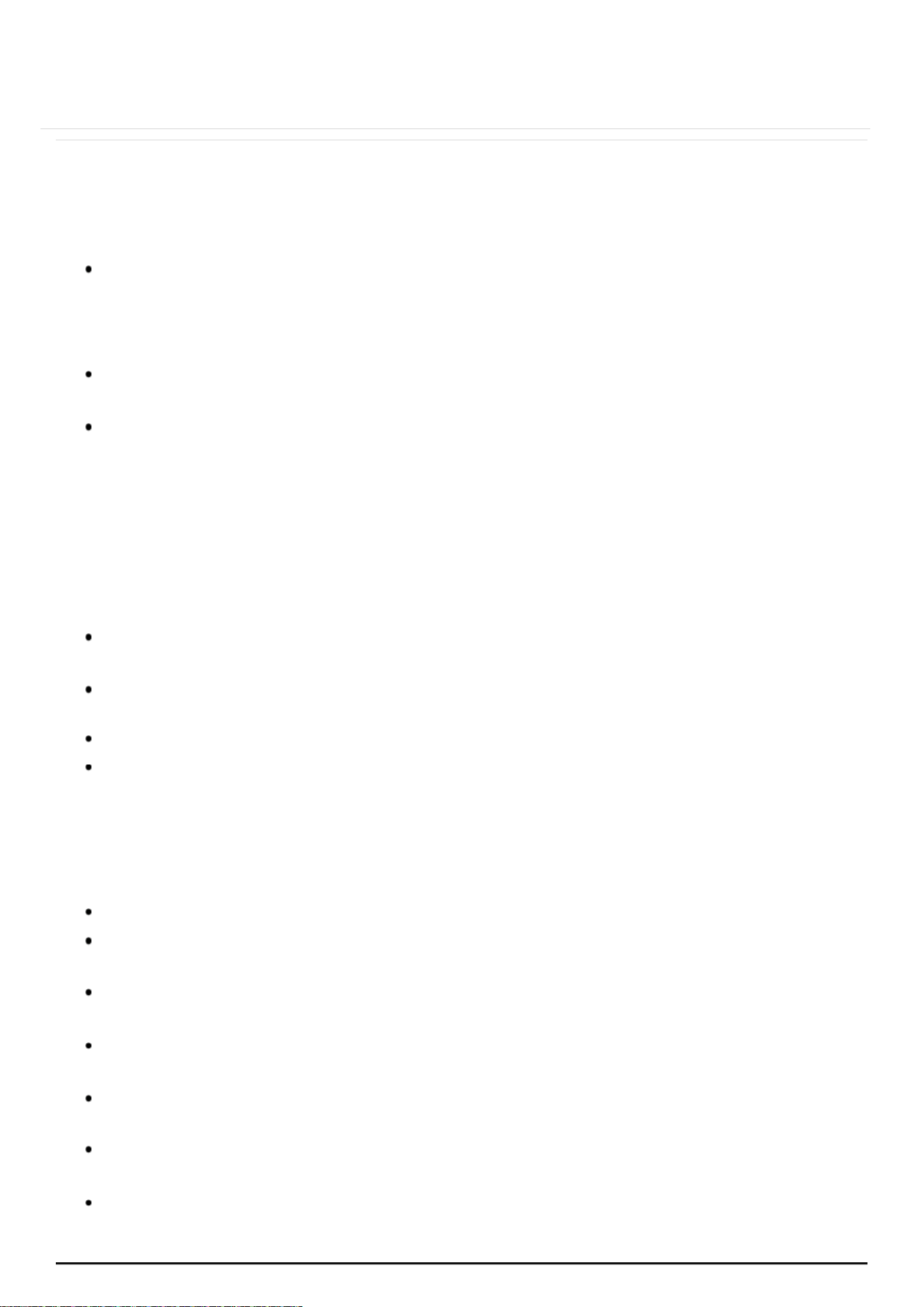
6.6 DUAL GAS REGULATOR VALVE INTRODUCTION
Product features:
This product has a low-pressure pipeline regulator valve, built-in voltage
regulator
for gas products.
Natural gas and liquefied petroleum gas conversion function, need
to be
set manually.
Operating Temperature: -20℃~60℃ .
Inlet pressure setting: of natural gas 6 in.wc / liquefied gas 11 in.wc of.
The performance parameters of the following table:
Installation Method:
·
Users to install the external threads coated with an appropriate
amount of
sealant to seal can also choose other sealing methods.
·
Out of gas regulator valve thread must match the connecting thread with
the gas.
·
Regulator valve installation location must be perpendicular.
·
After installation, open the gas source switch, and check valvebody
with soap and water connections for leaks.
web:brohn.com.au
P a g e | 22
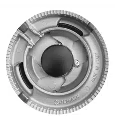
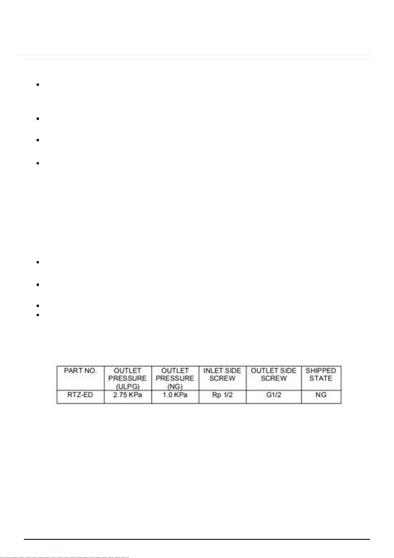
6.7 THE GAS KINDS OF CONVERSION METHOD:
·
Regulator valve factory set to natural gas or liquefied petroleum gas for
conversion of gas species, with special tools counterclockwise to open
the top
cover (Figure 1).
·
Remove the adapter from the top cover (Figure 2).
·
Ripped out the adapter inverted Replace the top cover (Figure 3).
·
Inverted the assembled adapters top cover, replace the regulator valve
(Figure 4) .
Please note:
Do not adjust the regulator valve body piece in the above
procedure,
otherwise it will affect the performance
parameters set in the factory.
Inlet connection region for flexible hose
After connecting to gas, check for leaks using soapy solution, never a naked
flame.
Gas pressure may be checked by test point located on regulator or LPG
test point adaptor.
Adjust regulator to the required pressure as shown on
data plate, check burner ignition & and the flame is burning correctly.
web:brohn.com.au
P a g e | 23
INSTALLATION METHOD:
When joining, use an adequate amount of sealant paste on external
threads or choose other appropriate sealing methods.
Out of gas regulator valve thread must match the connecting thread
with the gas
supply.
Regulator valve installation location must be perpendicular to the gas line.
After installation, open the gas source switch, and check valve body with
the gas
leak test kit or soapy water for leaks.
WARNING:
Regulator valve outlet pressure is set at the factory, please do not adjust in
order to
avoid the occurrence of safety accidents.
Turn off the gas source for any work on gas appliances. If you find any fault
of the
regulator valve operation, stop use and contact retailer or our
Customer Service.
Do not remove regulator or maintain other work on gas parts of this
appliance on your own.
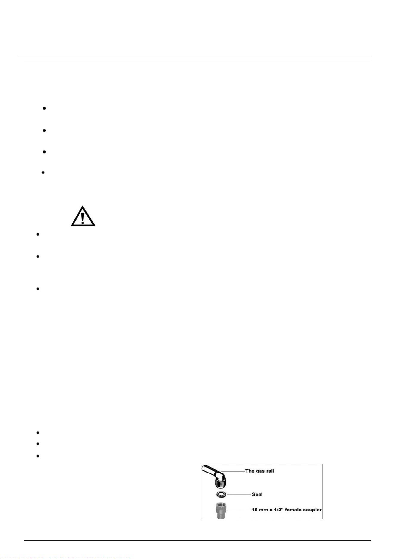
6.8 GAS SAFETY (INSTALLATION AND USE) REGULATIONS
IMPORTANT: The appliance MUST be connected to the gas supply by use of a
15 mm x ½” female coupler, seal, copper pipe and an isolation tap fitted in
an easily accessible position.
It is the law that all gas appliances are installed by a licensed gas fitter.
It is in your interest of safety to ensure installation compliance with the law.
Failure to install the hob correctly could invalidate the warranty, liability
claims and
lead to prosecution.
web:brohn.com.au
P a g e | 24
INSTALLATION PROCESS
Put the gas seal inside of the 15
mm x
½” female coupler.
Fully tighten the 15 mm x ½”
female
coupler and seal onto the
gas rail.
IMPORTANT: The female coupler must be positioned the right way up as shown
in the above picture.
Gas pressure may be checked on a semi-rapid hob burner. Remove the
appropriate
injector and attach a test nipple. Light the other burners and
observe that the gas
pressure complies with the gas standards in force.
IMPORTANT: On completion carry out a gas soundness test.
6.9 GAS ADJUSTMENT (CONVERSION TO LPG)
All gas adjustment or conversion work must be carried out by a
licensed gas fitter.
IMPORTANT: Always isolate the hob from the electricity and gas supply
before changing the injectors and/or adjusting the minimum flow of
the burners.
web:brohn.com.au
P a g e | 25
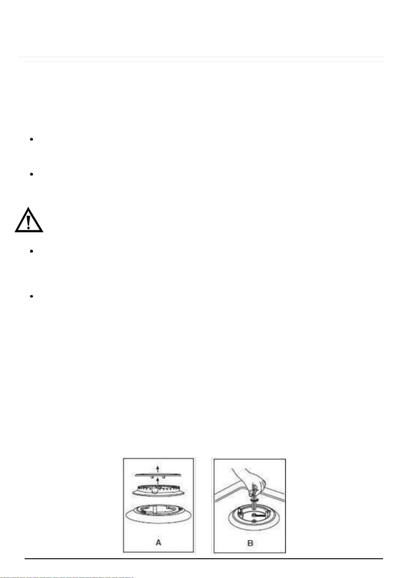
Remove the pan-stands, burners and flame spreaders (A).
Unscrew the injector (B) and replace it with the stipulated injector for
the new gas supply (see table on next page).
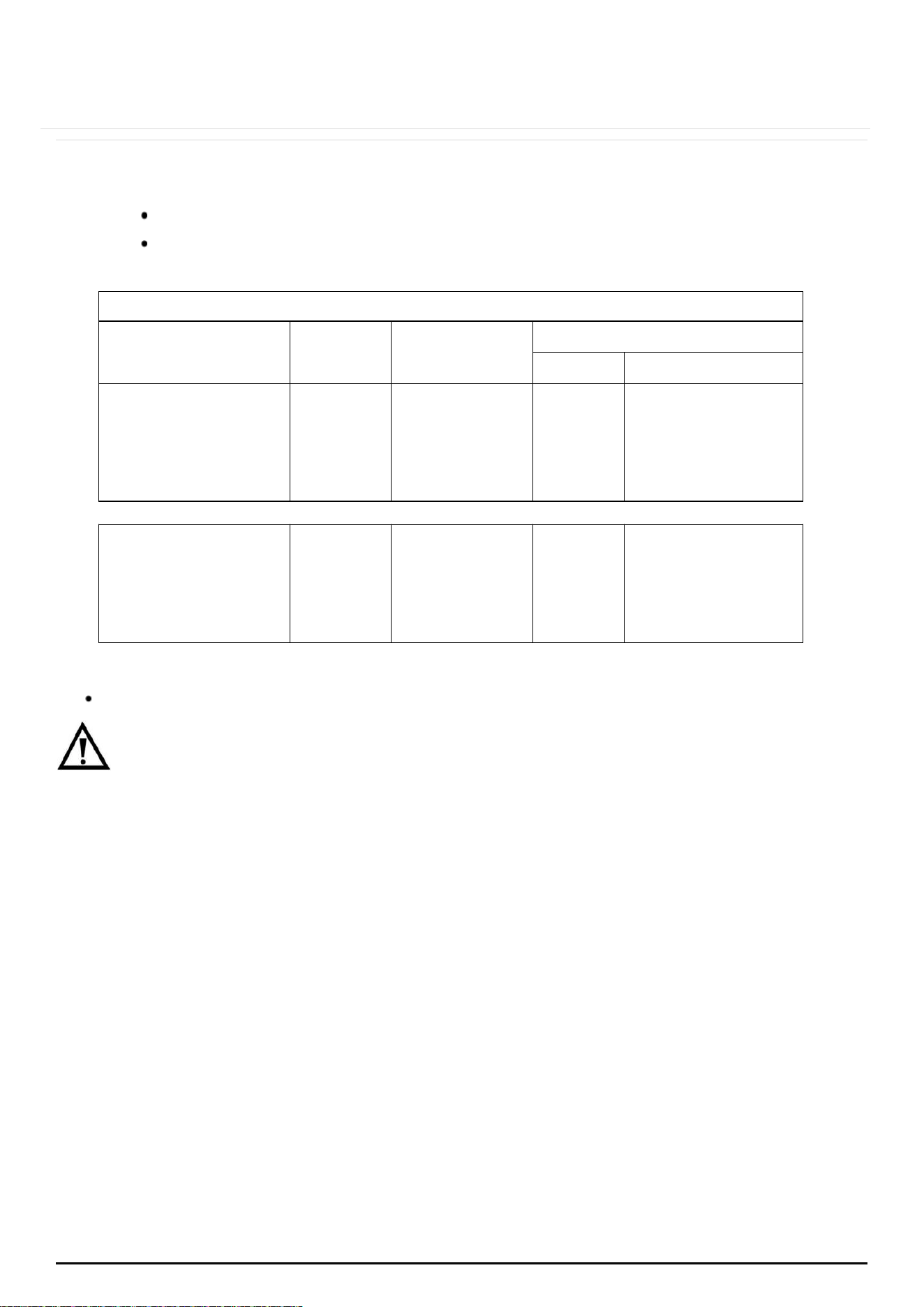
GENERAL INJECTORS TABLE
Kind of gas
Nozzle mm
Burners
Power (MJ/h)
Max.
Min.
Natural
1.80
1.49
1.16
0.85
Wok
Rapid
Semi-rapid
Auxiliary
14.4
10.8
6.5
3.6
6.3
5.4
3.24
1.8
Universal LPG
1.07
0.93
0.72
0.53
Wok
Rapid
Semi-rapid
Auxiliary
14.7
11.0
6.6
3.7
6.3
5.4
3.24
1.8
Reassemble all burners carefully; in particular you should ensure that the
flame spreader is correctly placed on the burner.
IMPORTANT: The minimum flow adjustment process must be completed
before the
appliance is used.
6.10MINIMUM FLOW ADJUSTMENT FOR HOB GAS TAPS
All work must be carried out by a licensed gas fitter.
IMPORTANT: Always isolate the hob from the electricity supply before
changing the injectors and/or adjusting the minimum flow of the burners.
web:brohn.com.au
P a g e | 26
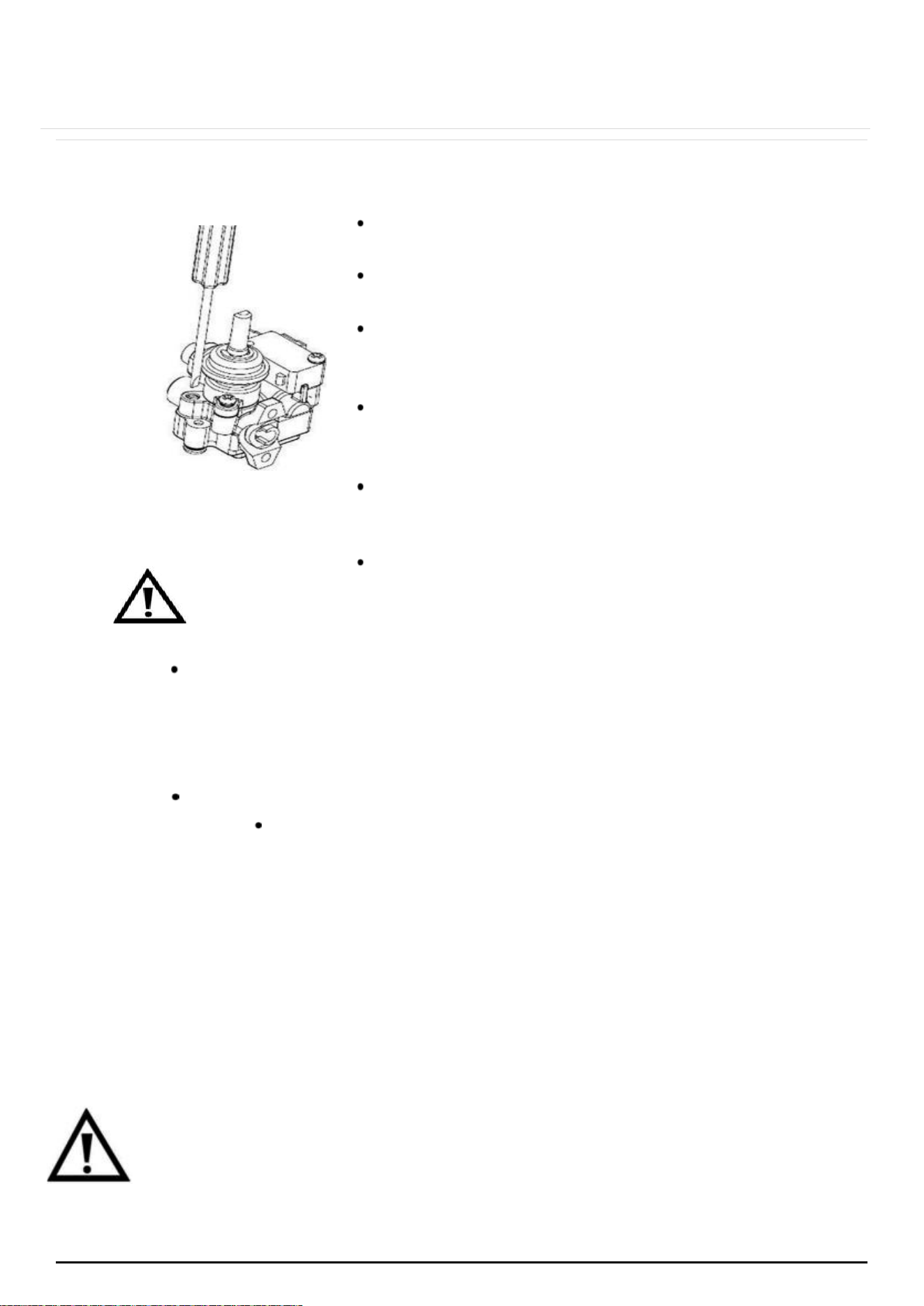
Remove all the pan supports, caps,
flame
spreaders and knobs.
Unscrew the screws of the panel,
then
remove the panel.
Install cap, flame spreader and knob of
the
burner. Switch the burner on and
set the knob at the minimum position.
Place a small bladed screwdriver on
the
screw to adjust the minimum flow
(as shown
in the image on the left).
Unscrew the adjusting screw in order
to
increase the gas flow or tighten the
adjusting
screw to decrease the gas flow.
The correct adjustment is obtained when the
flame has a length of about 3 – 4 mm.
For butane/propane gas, the adjusting screw must be
tightly screwed in.
Make sure that the flame does not go out by quickly
turning from
maximum flow to minimum flow. If it does
then remove the control knob and make further
adjustments to the gas flow,
testing it again once the
adjustment has been made.
Repeat this process for each one of the gas taps.
Install the panel and refit the caps, flame spreaders and
knobs after finished the adjustment.
IMPORTANT: WHEREVER THIS APPLIANCE IS INSTALLED, AT HOME, IN MARINE
CRAFT OR CARAVAN, IT SHALL NOT BE USED AS A SPACE HEATER.
6.11GAS TAP MAINTENANCE
These maintenance operations MUST ONLY be carried out by a licensed
gas fitter.
IMPORTANT: Before carrying out any maintenance operations, disconnect
the appliance from the gas and electricity supplies.
web:brohn.com.au
P a g e | 27
If a gas tap becomes stiff to operate, then you should proceed as follows:
Remove the control knobs, pan supports, burners, hob fixing screws and
clamps.
Remove the hob from the worktop and remove any underside protective
covers.
Disconnect the fixings holding the tap to the fascia panel and separate
the assembly. Then clean the cone and seating with a cloth
dampened with solvent.
Lightly smear the cone with high temperature grease, reassemble into
position and rotate a few times.
Remove the cone again and remove any excess grease ensuring that
the gas
ducts are not obstructed with grease.
Carefully reassemble the components and perform a gas soundness test.
If it becomes necessary to replace a gas tap, then you should proceed as follows:
Remove the control knobs, pan supports, burners, hob fixing screws and
clamps.
Remove the hob from the worktop and remove any underside protective
covers.
Disconnect the fixings holding the tap to the fascia panel and
separate the
assembly.
Disconnect the gas pipe from the gas tap, and then disassemble them from
the gas
rail by removing the fixing screws.
When fitting a new tap, ensure that a new gasket is used.
Reconnect the gas tap, perform a gas soundness test and then reassemble
the hob.
6.12ELECTRICAL CONNECTION
Power hard wiring connection of the cooktop must be installed by a licensed
electrician.
Before connecting the appliance, make sure that the supply voltage
marked on the
rating plate corresponds with your mains supply voltage.
Cable type: H05 RRF 3 core x 0.75 mm³ (Type RR-F <HAR> marked).
The mains supply cable and plug are supplied with this product.
web:brohn.com.au
P a g e | 28
6.13REPLACING THE MAINS SUPPLY CABLE
If the mains supply cable is damaged, then it must be replaced by a licensed
electrician
and at appropriate replacement.
The mains supply cable should be replaced in accordance with the following
instructions:
Switch the appliance off at your mains supply.
Open the box of the supply board.
Unscrew the clamp fixing the cable.
Replace the cable with one of the same length and in accordance
with the
specification given above.
The “green-yellow” earth wire must be connected to the earth terminal
marked “E”. It must be about 10 mm longer than the live and neutral wires.
The neutral wire must be connected to the terminal marked with letter (N).
The live
wire must be connected to the terminal marked with letter (L).
6.14INSTALLATION SUMMARY WARNINGS
Do not modify this appliance.
This appliance must be installed by an authorised installer, licensed gas fitter.
Prior to the installation, ensure that the local distribution conditions (nature
of the gas and gas pressure) and the adjustment of the appliance are
compatible.
The adjustment conditions for this appliance are stated on the label.
This appliance is not connected to a combustion products evacuation
device. It
should be installed and connected in accordance with
current installation
regulations. Particular attention should be given to
the relevant requirements
regarding ventilation.
Before installing, turn off the gas and electricity supply to the appliance.
All appliances containing any electrical components must be earthed.
Ensure that the gas pipe and electrical cable are installed in such a way
that they do not touch any parts of the appliance which may become hot.
Gas pipe or connector hose should not be bent or blocked by
any other
appliances.
web:brohn.com.au

P a g e | 29
Check the dimensions of the appliance as well as the dimensions of the
gap to be cut in the kitchen unit.
The panels located above the work surface, directly next to the appliance,
must be made of non-flammable material. Sealing materials should be
heat resistant to
prevent deterioration.
Turn on the appliance supply gas tap and light each burner. Check for a
clear blue
flame without yellow tipping.
If burners show any abnormalities check the following:
Burner lid on correctly
Flame spreader positioned correctly
Burner vertically aligned with injector nipple
A full operational test and a test for possible leakages must be carried out
by the fitter after installation.
The flexible hose shall be fitted in such a way that it cannot come into
contact with a moveable part of the housing unit and does not pass
through any space
susceptible of becoming congested.
Grease cranes produced at the factory to meet the requirements of all life
hobs.
web:brohn.com.au
P a g e | 30
web:brohn.com.au
7 DISPOSAL
This appliance requires special waste disposal. For
further
information regarding the treatment, recovery and
recycling of this product please contact your local
council, household waste
disposal service or the store of
purchase.
The packaging materials are recyclable.

P a g e | 31
8 CUSTOMER CARE
Please be advised that without the proof of purchase, your warranty may not be
valid,
keep the receipt.
STORE NAME/CONTACT DETAILS: ...............................................
PURCHASE DATE: ..........................................................................
PRODUCT MODEL N: ….................................................................
PRODUCT SERIAL N: .......................................................................
The warranty will be voided, if not installed by a licensed professional. For your own
protection, please record installer’s details:
INSTALLER’S TRADE NAME: ..................................................................
TRADE LICENCE N: ............................................................................
DATE OF INSTALLATION: …....................................................................
INSTALLATION RECEIPT: .......................................................................
For further information on the appliance, service, spare parts or to obtain
dimension and installation information, please contact our customer service or
visit website.
Please have above information and documents on hands before contacting customer
service
Email:[email protected]
Web:brohn.com.au
web:brohn.com.au