
Loading ...
Loading ...
Loading ...
MX101448—UN—17JUN20
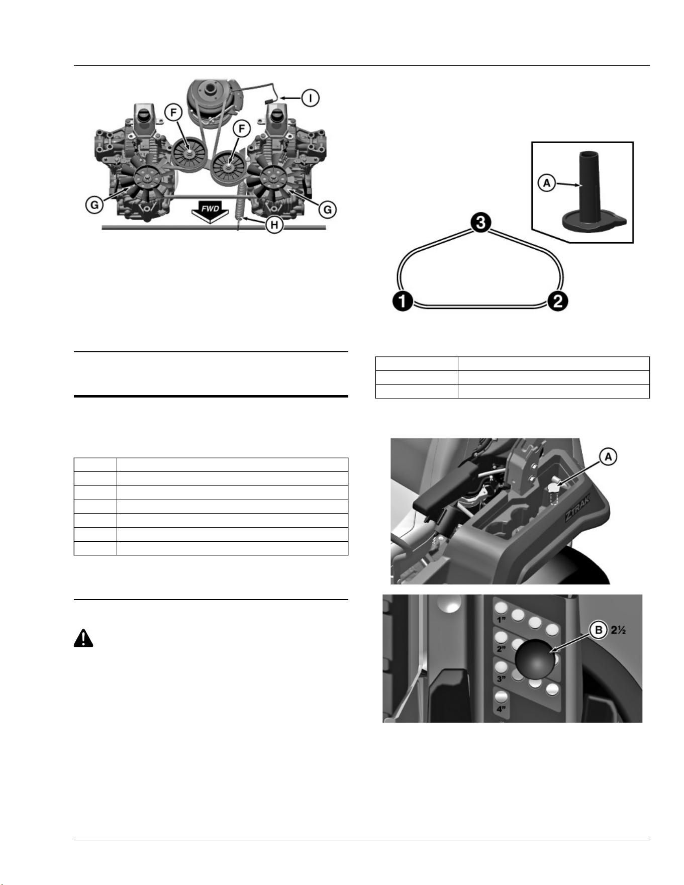
9. Position replacement belt around drive sheave on engine and
route belt through idler sheaves (F).
10. Route belt on transmission sheaves (G) and tension belt by
attaching spring (H) to rockshaft.
11. Insert the clutch wiring connector (I) to the main wiring harness.
12. Install mower deck.
13. Install style cover.
SB31882,00003FB-19-17JUN20
Service Mower
Mower Deck Identication
Mower decks in the following instructions are identied by a code
designation. The codes are as follows:
Code Description
48A 48 inch Accel Deep™
48HC 48 inch Edge™ High Capacity
54A 54 inch Accel Deep™
54HC 54 inch Edge™ High Capacity
60A 60 inch Accel Deep™
60HC 60 inch Edge™ High Capacity
Accel Deep is a trademark of Deere & Company
Edge is a trademark of Deere & Company
SB31882,0000405-19-04MAY20
Checking and Adjusting Mower Level
CAUTION: Avoid injury! Rotating blades are dangerous.
Before adjusting or servicing mower:
• Disconnect spark plug wires or battery negative (-) cable to
prevent engine from starting accidentally.
• Always wear gloves when handling mower blades or
working near blades.
NOTE: Mower deck wheels should not contact the ground when
leveling the deck.
1. Park machine safely on a at surface. (See Parking Safely in the
Safety section.)
2. Ensure that the front and rear tires are inated to the specied
pressure.
Specication
Front Tire—Pressure. . . . . . . . . . . . . . . . . . . . . . . . . . . . . . . . . . . . . . . . . . . . . . 103 kPa
(15 psi)
Rear Tire—Pressure. . . . . . . . . . . . . . . . . . . . . . . . . . . . . . . . . . . . . . . . . . . . . . . 69 kPa
(10 psi)
3. Position the caster wheels to the forward driving position.
Quick Leveling Method
MX101364—UN—01APR20
The quick leveling method measures at three points of the mower deck
using the deck leveling gauge (A).
Adjusting Point 1 Located on the left rear deck trim
Adjusting Point 2 Located on the right rear deck trim
Adjusting Point 3 Located on the front deck hanger bracket
NOTE: The deck leveling gauge (A) is stored in the tool box.
MX101363—UN—01APR20
MX101379—UN—01APR20
1. Insert the magnetic pin (B) at the 2-1/2 inch hole and lower the
deck. Once the deck is adjusted at the 2-1/2 inch cutting height
position, it is level and calibrated for all other cut height positions.
2. Adjust the mower deck wheels as necessary so they do not contact
the ground surface.
3. Remove the deck leveling gauge (A) from the tool box area.
4. Adjust mower deck side-to-side level:
Service Mower
43
Loading ...
Loading ...
Loading ...