
PLANNING GUIDE
84" HIGH INTEGRATED REFRIGERATION
RS1884F | RS2484F | RS2484S | RS2484V | RS2484W | RS3084F | RS3084S | RS3084W |
RS3684W

PAGE 290003672C PLANNING GUIDE INTEGRATED REFRIGERATION 84" VERSION 3 - SEPTEMBER 2024 © FISHER & PAYKEL LIMITED 2024
PLANNING GUIDE | INTEGRATED REFRIGERATION 84" INTEGRATED REFRIGERATION
This comprehensive Planning Guide provides you with the framework and tools to achieve your desired design outcome with Fisher & Paykel appliances. In this guide, you will
find a range of conceptual, detailed, and dimensional product information to bring your ideas to life and create spaces that truly reflect your vision.
CONCEPT DESIGN PAGE DEVELOPED AND DETAILED DESIGN PAGE DEVELOPED AND DETAILED DESIGN PAGE
Design Choices
84" High refrigeration overview 4
Purchase decision 5
Minimal configuration 6
Integrated framed 7
Specification Guide
Specification Guide - K Models 9
Specification Guide - E Models 10
Accessories
Handles 12
Handle specifications 13
Stainless steel panels and toe kicks 14
Data Sheets
18" Freezer 16
24" Refrigeration and freezers 17
24" Refrigerator freezer 18
24" Wine cabinet 19
30" Refrigeration and freezers 20
30" Refrigerator freezer 21
36" Refrigerator freezer 22
Planning Considerations
Hinge articulation 24
Panel variation examples 25
Door swing clearances 26
Door opening & gap clearances 27
Cavity Preparation
Single cavity dimensions 29
Dual and triple cavity dimensions 30
Multiple model cavity dimensions 31
Varied model cavity dimensions 32
Custom Door Panel Preparation
Toe kick and panels - low and high options 34
18" Freezer 35
24" Single panel refrigerators and freezers 36
24" Refrigerator freezers 37
24" Wine cabinet 38
30" Single panel refrigerators and freezers 39
30" Refrigerator freezers 40
36" Refrigerator freezer 41
Services
18" Freezer 43
24" Models 44
30" Models 45
36" Refrigerator Freezer 46
CONTENTS
CONTENTS
SUPPORT
For additional design planning and
installation support please contact the
Fisher & Paykel design support team
designsupport@fisherpaykel.com
i
i

© FISHER & PAYKEL LIMITED 2024 PAGE 390003672C PLANNING GUIDE INTEGRATED REFRIGERATION 84" - VERSION 3 - SEPTEMBER 2024
DESIGN CHOICES
The models shown in this Planning Guide may not be available in all markets and are subject to change at any time. Product specifications may vary from those shown. This Planning Guide should not be used as installation guidance for any product. Further information is required to safely and correctly install the
products featured here. Specific installation guidance will be available on our website fisherpaykel.com
PAGE 4PLANNING GUIDE INTEGRATED REFRIGERATION 84" - VERSION 3 - SEPTEMBER 202490003672C © FISHER & PAYKEL LIMITED 2024
Product
Model
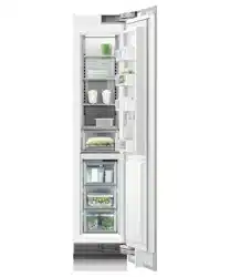
1 24" Wine Cabinet
91 bottle capacity, optional display capability. Two
independent temperature zones, four wine modes.
RS2484VL2K1, RS2484VR2K1
2 24" Integrated Refrigerator
Custom panel ready, with 12.4cu capacity
RS2484SRK1
3 24" Integrated Refrigerator with water
Custom panel ready, 12.4cu with internal water
dispenser.
RS2484SRHE1, RS2484SLHE1
RS2484SRHK1
4 30" Integrated Refrigerator
Custom panel ready, with 16.3cu capacity
RS3084SRK1
5 30" Integrated Refrigerator with water
Custom panel ready, 16.3cu with internal water
dispenser.
RS3084SRHE1, RS3084SLHE1
RS3084SRHK1
84" CAVITY HEIGHT MODELS
84" High refrigeration overview
PRODUCT SPECIFICATIONS | REFRIGERATION
REFRIGERATION
FREEZERREFRIGERATOR/FREEZER
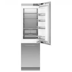
Product
Model
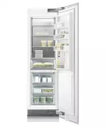
6 24" Integrated Refrigerator-Freezer
Custom panel ready, 12.1cu internal ice maker
and water dispenser.
RS2484WRUE1, RS2484WLUE1
RS2484WRUK1, RS2484WLUK1
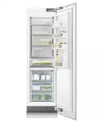
7 30" Integrated Refrigerator-Freezer
Custom panel ready, 15.9cu, internal ice maker
and water dispenser.
RS3084WRUE1, RS3084WLUE1
RS3084WRUK1, RS3084WLUK1
8 36" Integrated Refrigerator-Freezer
Custom panel ready, 19.2cu, internal ice maker
and water dispenser.
RS3684WRUVE1, RS3684WLUVE1
Product
Model
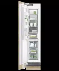
9 18" Freezer with Ice
Custom panel ready, 7.8cu and internal ice
maker.
RS1884FRJE1, RS1884FLJE1
RS1884FLJK1
!0 24" Integrated Freezer with ice
Custom panel ready, 11.9cu and internal ice
maker.
RS2484FRJE1, RS2484FLJE1
RS2484FLJK1
!1 30" Integrated Freezer with ice
Custom panel ready, 15.6cu and internal ice
maker.
RS3084FRJE1, RS3084FLJE1
RS3084FLJK1
1 2 3 4 5 6 7 8 9 !0 !1
<< CONTENTS
The models shown in this Planning Guide may not be available in all markets and are subject to change at any time. Product specifications may vary from those shown. This Planning Guide should not be used as installation guidance for any product. Further information is required to safely and correctly install the
products featured here. Specific installation guidance will be available on our website fisherpaykel.com
PAGE 5PLANNING GUIDE INTEGRATED REFRIGERATION 84" - VERSION 3 - SEPTEMBER 202490003672C © FISHER & PAYKEL LIMITED 2024
DOOR SWING
900 or 1150
DESIGN CHOICES | PURCHASE DECISION
Purchase decision
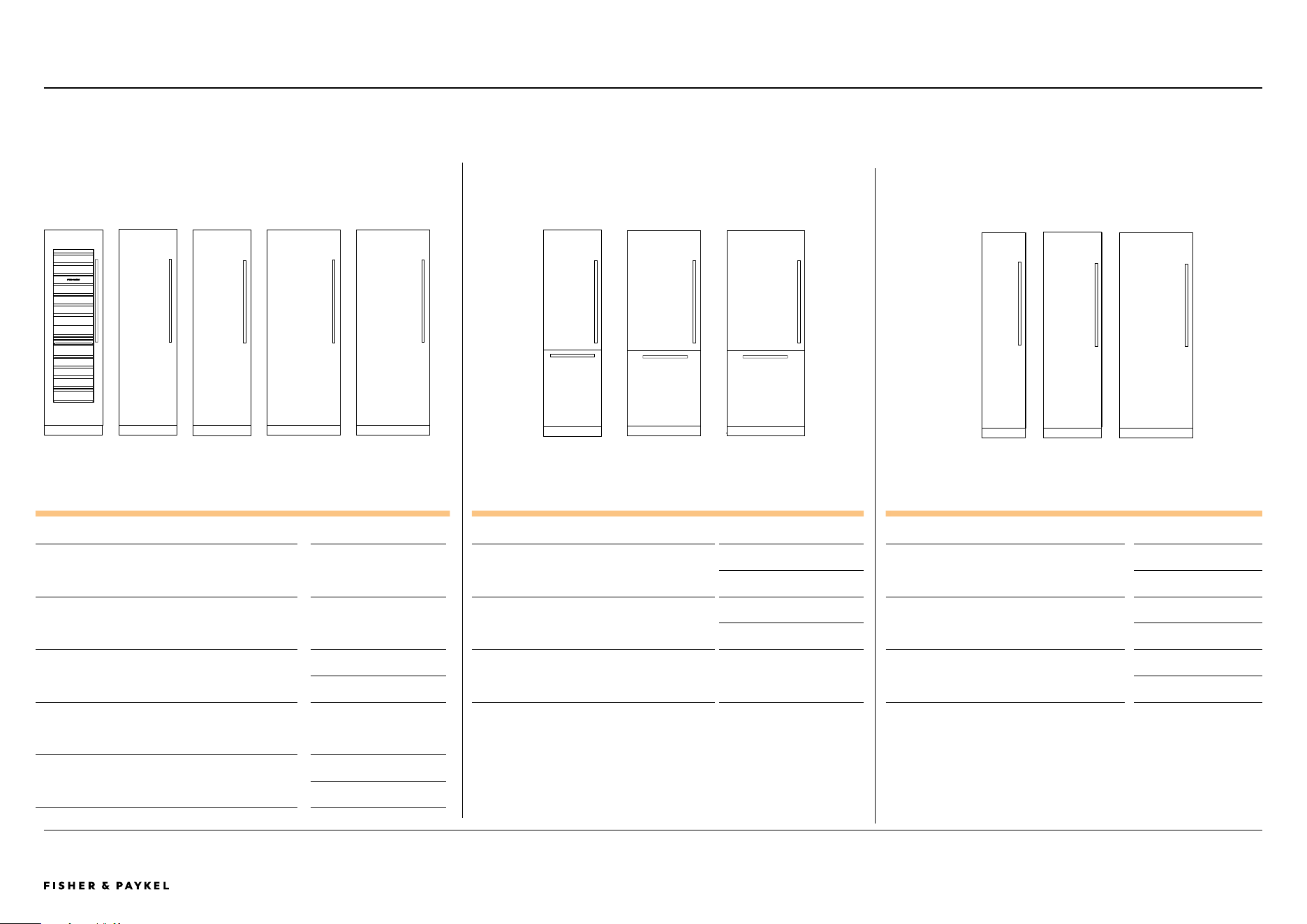
OVERVIEW
INTEGRATED PANEL OPTIONS STAINLESS STEEL PANEL OPTIONS
PANEL HEIGHT
Panel heights can vary from
77 ⅞" to 81 ⅞".
FINISH: Match or contrast
with your kitchen cabinets.
CUSTOM HANDLES
Select Fisher & Paykel
handles or customize handles
to match your kitchen style.
ASSISTED OPENING
ACCESSORY:
Push or pull-to-open
functionality, check
fisherpaykel.com for
availablity.
TOE KICK HEIGHT
Toe kick heights - 2" to 6".
FINISH: Match or contrast
with your kitchen cabinets
PANEL
79 ⅞" high, left or right
hinging.
FINISH: Stainless Steel.
ACCESSORY HANDLE
Select Fisher & Paykel
handles.
TOE KICK HEIGHT
4" high, lengths available
from 18" to 72".
FINISH: Stainless Steel.
HINGING
Left or right*
ALL MODELS
*Some models require a hinge
conversion kit
<< CONTENTS
The models shown in this Planning Guide may not be available in all markets and are subject to change at any time. Product specifications may vary from those shown. This Planning Guide should not be used as installation guidance for any product. Further information is required to safely and correctly install the
products featured here. Specific installation guidance will be available on our website fisherpaykel.com
PAGE 6PLANNING GUIDE INTEGRATED REFRIGERATION 84" - VERSION 3 - SEPTEMBER 202490003672C © FISHER & PAYKEL LIMITED 2024
DESIGN CHOICES | PRODUCT CONFIGURATION
4
3
2
1
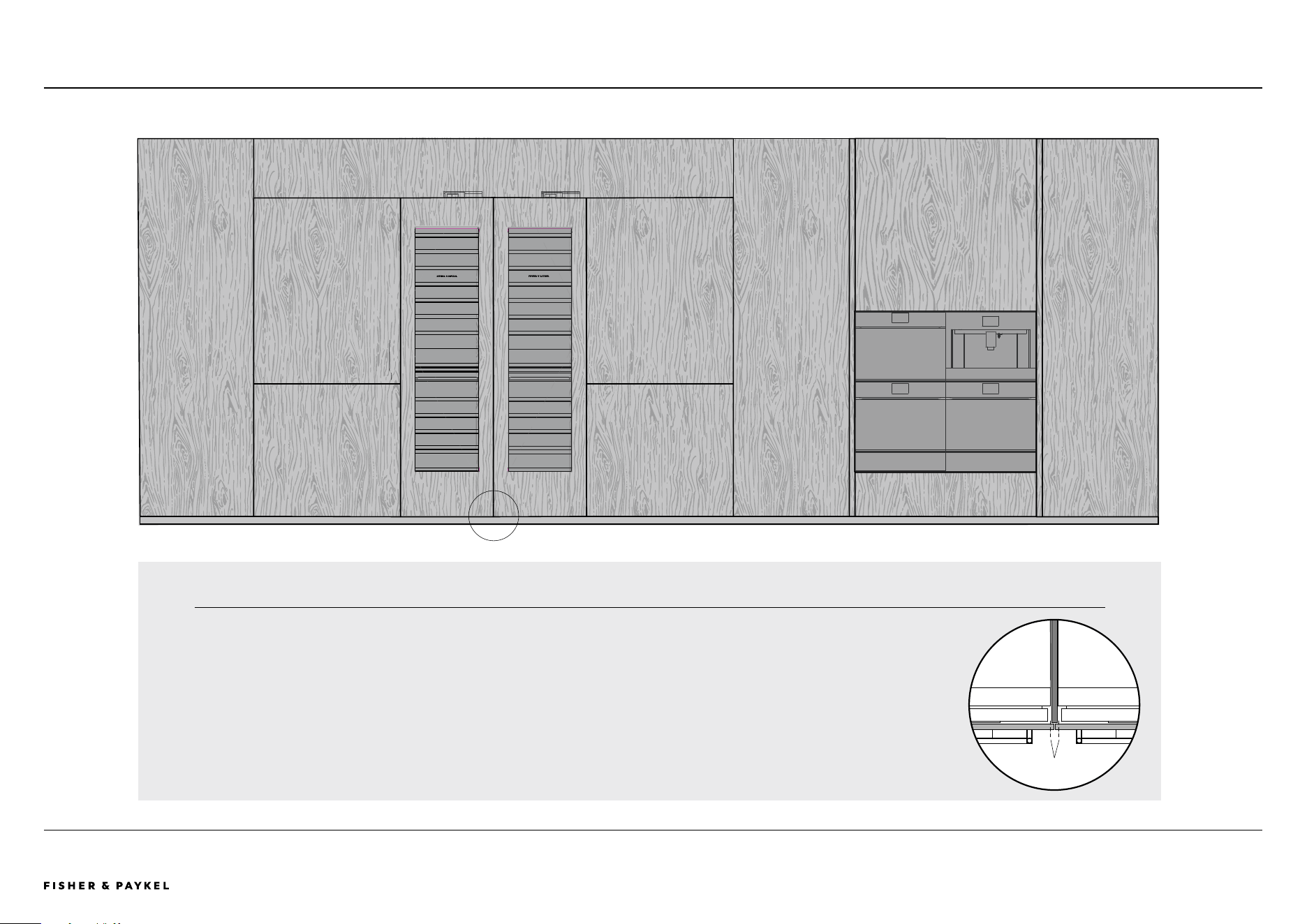
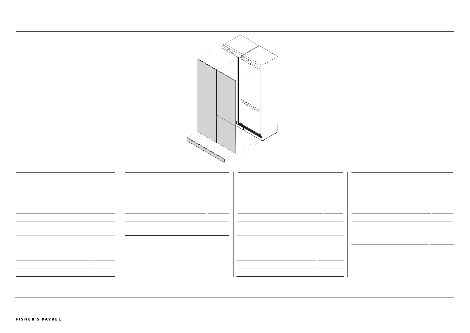
INTEGRATED MINIMAL
Minimal configuration
INTEGRATED MINIMAL
1 36" Refrigerator Freezer with ice, water
2 24" Wine cabinet
3 24" Wine cabinet
4 36" Refrigerator Freezer with ice, water
5 24" Handless combination speed oven (OM24NMTNB1), handleless oven (OB24SMPTNB1) and warming drawer (WB24SMB1-SET)
6 24" Built-in coee maker (EB24MSB1), 24" handleless oven (OB24SMPTNB1) and vacuum drawer (VB24SMB1-SET)
In this configuration:
Ceiling height: 94 ½" Product cavity height: 84" Toe kick: 2" Panel height: 81 ⅞, Panel gap and opening clearance: ⅛"
5 6
The maximum
number of appliances
per cavity is three.
If two cavities are
required, a spacer
with wider panels
can be used.
Line of standard
panel width
<< CONTENTS
The models shown in this Planning Guide may not be available in all markets and are subject to change at any time. Product specifications may vary from those shown. This Planning Guide should not be used as installation guidance for any product. Further information is required to safely and correctly install the
products featured here. Specific installation guidance will be available on our website fisherpaykel.com
PAGE 7PLANNING GUIDE INTEGRATED REFRIGERATION 84" - VERSION 3 - SEPTEMBER 202490003672C © FISHER & PAYKEL LIMITED 2024
DESIGN CHOICES | PRODUCT CONFIGURATION INTEGRATED FRAMED
3
1
2
4
5
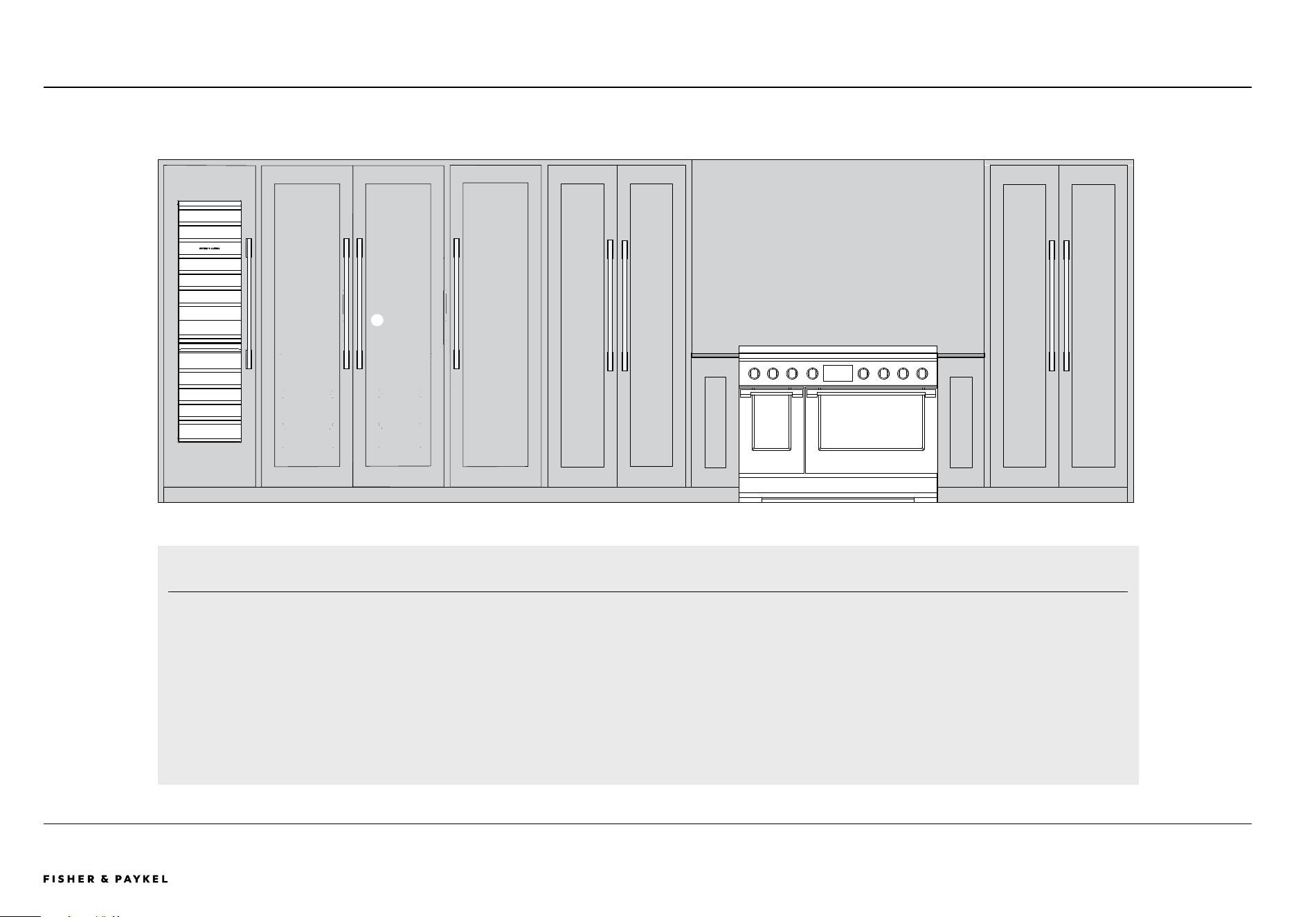
Integrated framed
INTEGRATED FRAMED
1 24" Wine cabinet
2 24" Refrigerator with water
3 24" Refrigerator with water
4 24" Freezer with ice
5 Free-standing RIV3-486 professional induction range
6 Professional round handles aluminium
In this configuration:
Product cavity height: 84" Toe kick: 4" Panel height: 79 ⅞, Panel gap and opening clearance: ⅛"
6
<< CONTENTS

© FISHER & PAYKEL LIMITED 2024 PAGE 890003672C PLANNING GUIDE INTEGRATED REFRIGERATION 84" - VERSION 3 - SEPTEMBER 2024
SPECIFICATION GUIDE

The models shown in this Planning Guide may not be available in all markets and are subject to change at any time. Product specifications may vary from those shown. This Planning Guide should not be used as installation guidance for any product. Further information is required to safely and correctly install the
products featured here. Specific installation guidance will be available on our website fisherpaykel.com
PAGE 9PLANNING GUIDE INTEGRATED REFRIGERATION 84" - VERSION 3 - SEPTEMBER 202490003672C © FISHER & PAYKEL LIMITED 2024
OVERVIEW
These Integrated Columns oer seamless design, flexible
installation, and the ability to customize to match existing
cabinetry. Features include two Variable Temperature
Zones, bright LED lighting, and ActiveSmart™ technology
for optimal freshness. With options for internal ice makers,
joining kits, and premium finishes, these models provide
lasting durability and a sleek design.
FEATURES
1 Customize with kitchen cabinetry or a stainless steel door
panel accessory
2 Seamless fit with only ⅛” gaps, featuring no visible hinges
or grilles
3 Mix and match columns, install separately or pair together
4 Two Variable Temperature Zones with options for Fridge,
Pantry, Chill, Freeze, Soft Freeze, and Deep Freeze modes
5 Flexible installation with left or right hinge options
6 Intuitive, easy-to-use touchscreen interface with Wi-Fi
compatibility
7 ActiveSmart™ technology maintains ideal temperature for
fresher food
8 Bright LEDs illuminate ceiling, shelves, bins, and tray
9 Joining kit for pairing units; front adjustable levelling feet
for easy installation
!0 Premium finish with robust materials for long-lasting
durability and sleek aesthetic
SPECIFICATION GUIDE | Integrated Refrigeration 84" High
Specification Guide - K Models
RS3084WRUK1, RS3084WLUK1 - with Custom Door Panels
RS3084WRUK1, RS3084WLUK1 - with Custom Door Panels
PRODUCT OVERVIEW
REFRIGERATION
RS2484VL2K1, RS2484VR2K1
Integrated Column Wine Cabinet, 24"
RS2484SRK1
Integrated Column Refrigerator, 24"
RS2484SRHK1
Integrated Column Refrigerator, 24", Water
RS3084SRK1
Integrated Column Refrigerator, 30"
RS3084SRHK1
Integrated Column Refrigerator, 30", Water
FREEZER
RS1884FLJK1
Integrated Column Freezer, 18", Ice
RS2484FLJK1
Integrated Column Freezer, 24", Ice
RS3084FLJK1
Integrated Column Freezer, 30", Ice & Water
REFRIGERATOR FREEZER
RS2484WRUK1, RS2484WLUK1,
Integrated Refrigerator Freezer, 30", Ice & Water
RS3084WRUK1, RS3084WLUK1
Integrated Refrigerator Freezer, 30", Ice & Water
All models can achieve opposite hinge location using hinge kits
<< CONTENTS

The models shown in this Planning Guide may not be available in all markets and are subject to change at any time. Product specifications may vary from those shown. This Planning Guide should not be used as installation guidance for any product. Further information is required to safely and correctly install the
products featured here. Specific installation guidance will be available on our website fisherpaykel.com
PAGE 10PLANNING GUIDE INTEGRATED REFRIGERATION 84" - VERSION 3 - SEPTEMBER 202490003672C © FISHER & PAYKEL LIMITED 2024
OVERVIEW
Experience the pinnacle of refrigeration design with our
most advanced Columns. Featuring elegant interiors and
options for ice and water, these models embody premium
functionality and style. Engineered for energy eciency,
they seamlessly integrate alone or paired. Available in
various sizes, they ensure a perfect fit for any kitchen.
SPECIFICATION GUIDE | Integrated Refrigeration 84" High
Specification Guide - E Models
RS2484FRJE1, RS2484SRHE1 - with Custom Door Panel
RS3684WRUVE1 - with Custom Door Panel
PRODUCT OVERVIEW
REFRIGERATION
RS2484SRHE1, RS2484SLHE1
Integrated Column Refrigerator, 24", Water
RS3084SRHE1, RS3084SLHE1
Integrated Column Refrigerator, 30", Water
FREEZER
RS1884FRJE1, RS1884FLJE1
Integrated Column Freezer, 18", Ice
RS2484FRJE1, RS2484FLJE1
Integrated Column Freezer, 24", Ice
RS3084FRJE1, RS3084FLJE1
Integrated Column Freezer, 30", Ice
REFRIGERATOR FREEZER
RS2484WRUE1, RS2484WLUE1
Integrated Refrigerator Freezer, 24", Ice & Water
RS3084WRUE1, RS3084WLUE1
Integrated Refrigerator Freezer, 30", Ice & Water
RS3684WRUVE1, RS3684WLUVE1
Integrated Refrigerator Freezer, 36", Ice & Water
FEATURES
1 Premium interior for a refined look and feel, this model is
the highlight of our Integrated Columns collection
2 Designed for optimal energy performance and maximum
efficiency
3 Mix and match columns, install separately or pair together
4 Seamless fit with only ⅛” gaps, featuring no visible hinges
or grilles
5 Customize with kitchen cabinetry or a stainless steel door
panel accessory
6 Two Variable Temperature Zones with options for Fridge,
Pantry, Chill, Freeze, Soft Freeze, and Deep Freeze modes
7 Intuitive, easy-to-use touchscreen interface with Wi-Fi
compatibility
8 Flexible installation with left or right hinge options
9 Joining kit for pairing units; front adjustable levelling feet
for easy installation
!0 ActiveSmart™ technology maintains ideal temperature for
fresher food
<< CONTENTS

© FISHER & PAYKEL LIMITED 2024 PAGE 1190003672C PLANNING GUIDE INTEGRATED REFRIGERATION 84" - VERSION 3 - SEPTEMBER 2024
ACCESSORIES
The models shown in this Planning Guide may not be available in all markets and are subject to change at any time. Product specifications may vary from those shown. This Planning Guide should not be used as installation guidance for any product. Further information is required to safely and correctly install the
products featured here. Specific installation guidance will be available on our website fisherpaykel.com
PAGE 12PLANNING GUIDE INTEGRATED REFRIGERATION 84" - VERSION 3 - SEPTEMBER 202490003672C © FISHER & PAYKEL LIMITED 2024
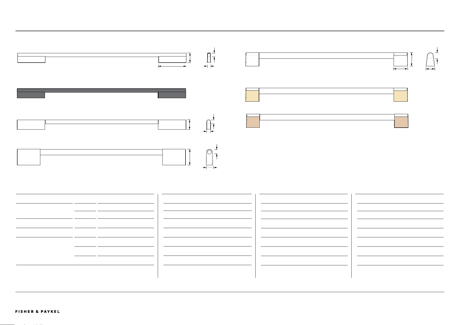
HANDLESPRODUCT SPECIFICATIONS | ACCESSORIES
SINGLE DOOR MODELS FINISH MODELS
1 Contemporary Square Fine
Aluminium AHD5RDSF
Black AHD5RDSFB
2 Contemporary Round
Aluminium AHSRD84
3 Classic Handle
Aluminium AHCLRDSF
4 Professional Round
Aluminium AHC-RD84
Brass AHP3RDSFBA
Dark Copper
AHP3RDSFDC
*See fisherpaykel.com to check availability.
HANDLES
24" REFRIGERATOR FREEZER MODELS
AHD5RD2484W
AHD5RD2484WB
AHSRD2484W
AHCLRD2484W
AHCRD2484W
AHP3RD2484WBA
AHP3RD2484WDC
30" REFRIGERATOR FREEZER MODELS
AHD5RD3084W
AHD5RD3084WB
AHSRD3084W
AHCLRD3084W
AHCRD3084W
AHP3RD3084WBA
AHP3RD3084WDC
36" REFRIGERATOR FREEZER MODELS
AHD5RD3684W
AHD5RD3684WB
AHSRD3684W
AHCLRD3684W
AHCRD3684W
AHP3RD3684WBA
AHP3RD3684WDC
Round
Prof round
Round
Prof round
Round
Prof round
1
2
4
1 ⅝"
11/16"
1 ⅝"
⅝"
2 ¼"
1"
Handles
Round
Prof round
Round
Prof round
Round
Prof round
1 7/16"
1 ¾"
4 23/32"
11/16"
⅝"
Round
Prof round
3
2 5/32"
⅞"
¾"
<< CONTENTS
PAGE 1390003672C PLANNING GUIDE INTEGRATED REFRIGERATION 84" VERSION 3 - SEPTEMBER 2024 © FISHER & PAYKEL LIMITED 2024
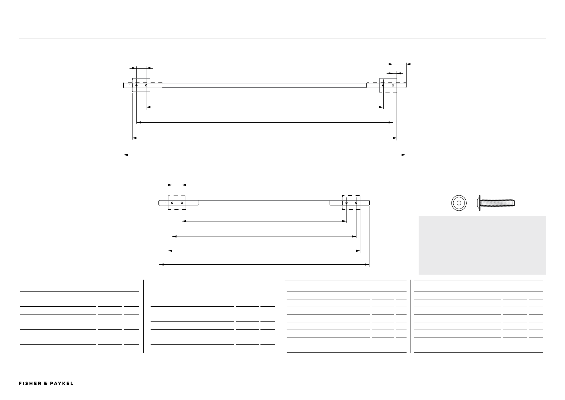
HANDLE SPECIFICATIONSPRODUCT SPECIFICATIONS | ACCESSORIES
SINGLE DOOR MODELS
Vertical Handle
in mm
A
Length between outer screws 28 1/32 712
B
Length between screws 30 13/32 773
24" REFRIGERATOR FREEZER MODELS
Vertical Handle
in mm
A
Length between inner screws 23 3/32 587
B
Length between outer screws 25 15/32 647
Horizontal Handle
C
Length between inner screws 13 29/32 353
D
Length between outer screws 16 9/32 414
E
Overall length - Professional Round 14 7/16 367
F
Overall length - Contemporary 19 7/ 16 494
Handle specifications
B
A
C
D
30" REFRIGERATOR FREEZER MODELS
Vertical Handle
in mm
A
Length between inner screws 23 3/32 587
B
Length between outer screws 25 15/32 647
Horizontal Handle
C
Length between inner screws 19 29/32 506
D
Length between outer screws 22 9/32 566
E
Overall length - Professional Round 22 27/32 580
F
Overall length - Contemporary 22 7/ 16 646
36" REFRIGERATOR FREEZER MODELS
Vertical Handle
in mm
A
Length between inner screws 23 3/32 587
B
Length between outer screws 25 15/32 647
Horizontal Handle
C
Length between inner screws 25 29/32 658
D
Length between outer screws 28 9/32 718
E
Overall length - Professional Round 28 13/16 748
F
Overall length - Contemporary 31 13/32 798
1 3/16"
VERTICAL HANDLE (DOOR)
HORIZONTAL HANDLE (DRAWER)
SOCKET SCREWS
M5 X 25mm Pan Head Socket Screw
(4 per handle) suits standard 3/4" (19mm) panel.
Thicker panels may require counter-boring or longer
screws.
Contemporary Handles
Professional Round Handle
Professional Round Handle
Contemporary Handles
E
F
1 9/16"
9/32"
1 3/16"
26 ⅓2"
28 ⅝"
<< CONTENTS
PAGE 1490003672C PLANNING GUIDE INTEGRATED REFRIGERATION 84" VERSION 3 - SEPTEMBER 2024 © FISHER & PAYKEL LIMITED 2024
STAINLESS STEEL PANELS AND Toe kickSPRODUCT SPECIFICATIONS | ACCESSORIES
1 STAINLESS STEEL PANELS
24" REFRIGERATOR FREEZER (23 ¾" wide)
MODEL
Left hand hinging (23 ¾" wide)
RD2484WLD
Right hand hinging (23 ¾" wide)
RD2484WRD
24" WINE CABINET MODEL
Left hand hinging
(23 ¾" wide)
RD2484VL4
Right hand hinging (23 ¾" wide)
RD2484VR4
30" REFRIGERATOR FREEZER MODEL
Left hand hinging (29 ¾" wide)
RD3084WLD
Right hand hinging (29 3/4" wide)
RD3084WRD
36" REFRIGERATOR FREEZER MODEL
Left hand hinging (35 3/4" wide)
RD3684WLD
Right hand hinging (35 3/4" wide)
RD3684WRD
SINGLE TOE KICK MODEL
18" Model (18" wide)
AKRS1804
24" Models (24" wide)
AKRS2404
30" Models (30" wide)
AKRS3004
36" Models (36" wide)
AKRS3604
2 STAINLESS STEEL TOE KICKS
MULTIPLE MODEL
24" + 24" + 30" (78" wide)
AKRS7804
18" + 30" + 30" (78" wide)
AKRS7804
24" + 30" + 30" (84" wide)
AKRS8404
24" + 24" + 36" (84" wide)
AKRS8404
DOUBLE TOE KICK MODEL
18" Models
N/A
24" Models (48" wide)
AKRS4804
30" Models (60" wide)
AKRS6004
36" Models (72" wide)
AKRS7204
TRIPLE TOE KICK MODEL
18" Models
N/A
24" Models (72" wide)
AKRS7204
30" Models (90" wide)
N/A
36" Models
N/A
All Models
AJ-RS84LR A joiner kit is supplied with freezer models: RS3084FLJE1, RS3084FLJK1, RS2484FLJE1, RS2484FLJK1, RS1884FRJE1, RS1884FLJK1 and wine models: RS2484VR2K1, RS2484VL2K1
3 JOINER KITS* (FOR MULTIPLE PRODUCT INSTALLATION)
1
2
3
Stainless steel panels and toe kicks
PRODUCT SPECIFICATIONS | ACCESSORIES
SINGLE DOOR MODEL LEFT MODEL RIGHT
18" Model (17 ¾" wide)
RD1884L4D RD1884R4D
24" Models (23 ¾" wide)
RD2484L4D RD2484R4D
30" Models (23 ¾" wide)
RD3084L4D RD3084R4D
<< CONTENTS

© FISHER & PAYKEL LIMITED 2024 PAGE 1590003672C PLANNING GUIDE INTEGRATED REFRIGERATION 84" - VERSION 3 - SEPTEMBER 2024
DATA SHEETS
IMPORTANT NOTE: Throughout this guide, dimensions may vary by ±2mm
(1/16''). Please read the Installation Guide for detailed information on
installing the product. For full installation instructions visit fisherpaykel.com
PAGE 1690003672C PLANNING GUIDE INTEGRATED REFRIGERATION 84" - VERSION 3 - SEPTEMBER 2024© FISHER & PAYKEL LIMITED 2024
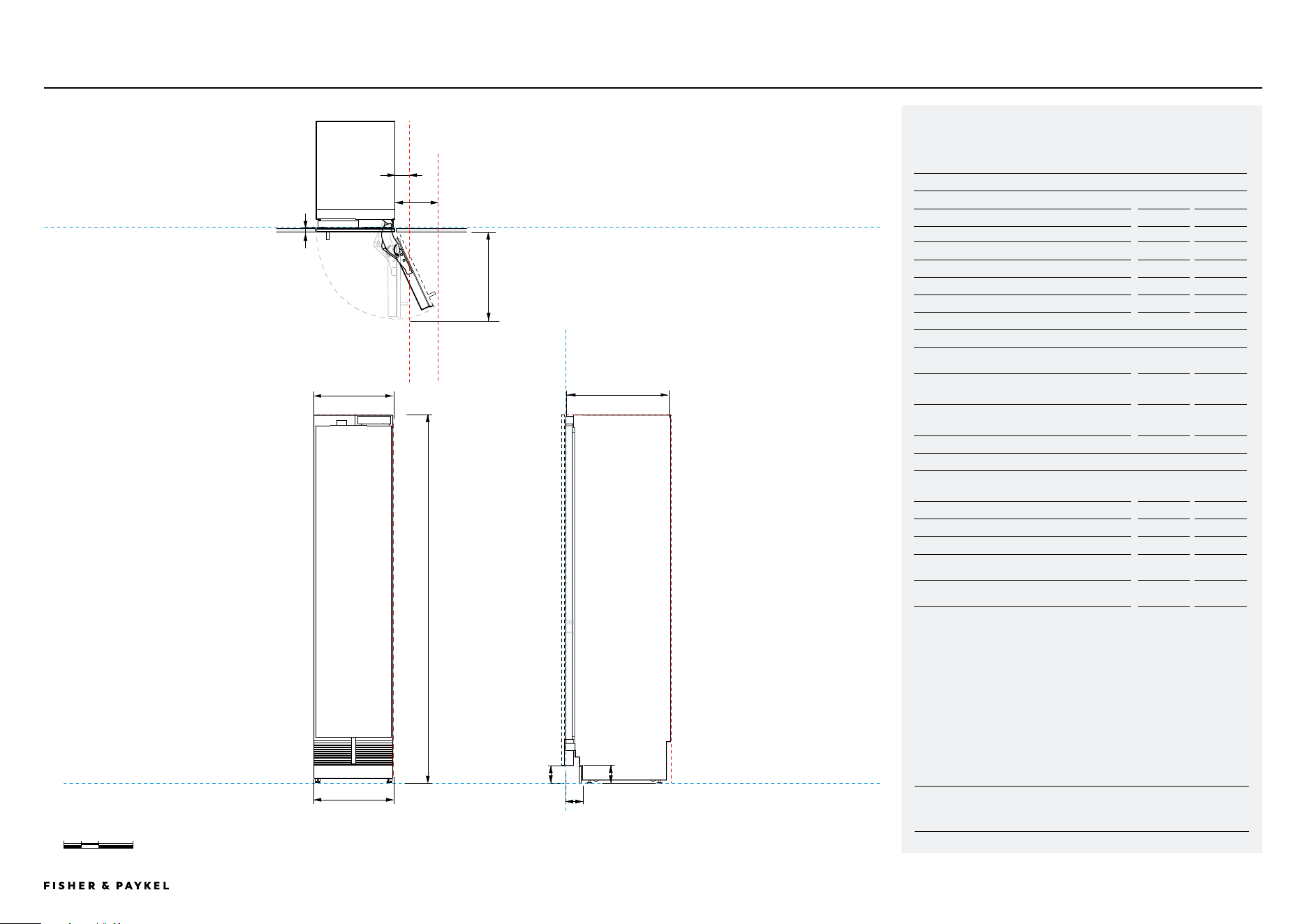
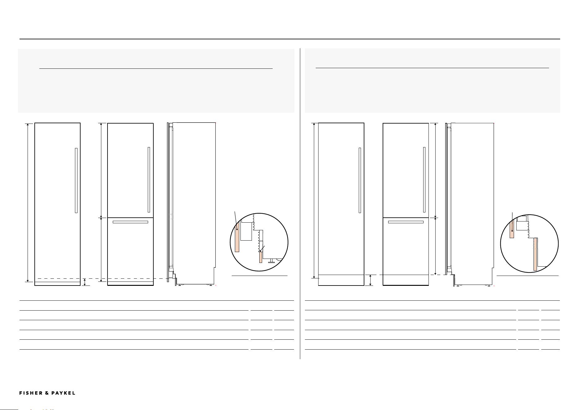
Model no:
RS1884FRJE1, RS1884FLJK1
Product Dimensions
in
mm
a Overall height
84
2134
B Overall width
17 3/4
451
c Overall depth (excluding door panels)
24
610
D Floor to bottom of door
4
102
E Depth of toe kick (excluding panels)
2 7/8 - 4
73 - 102
F Height of toe kick
2 - 6
50 - 152
G Width of toe kick
17 7/8
454
Door/Drawer Opening Dimensions*
H Minimum door clearance** to adjacent wall*
(90° – reduced internal access)*
4 5/16
110
I Minimum door clearance** to adjacent wall*
(115° – full internal access)
11 1/2
292
J Depth of door (90° open) measured from
front of door
20
508
Clearance Dimensions*
Minimum cabinetry gap
clearance from edge of
door panel
1/8
3
Cavity overall height
84
2134
Cavity overall width (single)
18
457
Cavity overall width (dual)
36
915
Minimum overall depth (shallow) of cavity when
services are located outside of cavity****
25
635
Minimum overall depth (deep) of cavity when
services are located at rear of cavity****
25 19/32
650
* Custom panels to be manufactured & fitted by cabinetmaker.
** 3 15/16" (100mm) tall stainless steel toe kick panel available. Adjust
the height of the door panel accordingly.
*** Door handle kit is available as an optional accessory.
****Assumes a door panel depth of 3/4" (19mm).
18" Freezer
DATA SHEET | 18" REFRIGERATION RS1884FRJE1, RS1884FLJK1
INDICATES CABINETRY / PRODUCT DATUM -------------------------
INDICATES CABINETRY CLEARANCES --------------------------------
DATUM :
FLOOR (LEVEL)
0 100 200 400
millimetres
C
A
B
D F
I
H
J
PROFILE VIEWFRONT VIEW
PLAN VIEW
DATUM: FRONT OF CHASSIS
DATUM: FRONT OF CHASSIS
CLEARANCE: DOOR AT 115⁰
CLEARANCE: DOOR AT 90⁰
84"
17 ¾"
E
G
<< CONTENTS
IMPORTANT NOTE: Throughout this guide, dimensions may vary by ±2mm
(1/16''). Please read the Installation Guide for detailed information on
installing the product. For full installation instructions visit fisherpaykel.com
PAGE 1790003672C PLANNING GUIDE INTEGRATED REFRIGERATION 84" - VERSION 3 - SEPTEMBER 2024© FISHER & PAYKEL LIMITED 2024
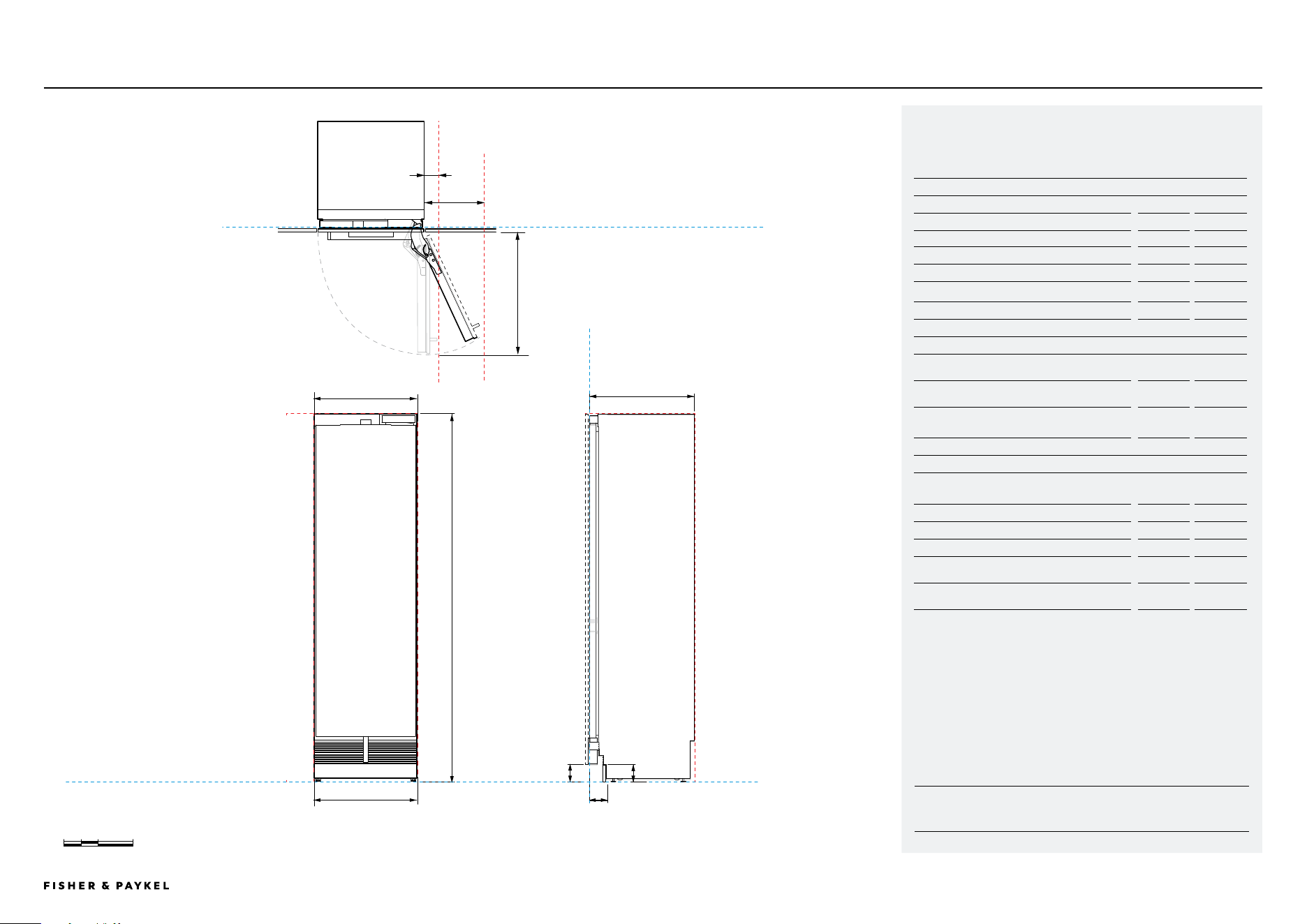
Model no:
RS2484SRHE1, RS2484SLHE1, RS2484FRJE1, RS2484FLJE1,
RS2484SRK1, RS2484SRHK1, RS2484FLJK1
Product Dimensions
in
mm
a Overall height
84
2134
B Overall width
23 ¾
603
c Overall depth (excluding door panels)
24
610
D Floor to bottom of door
4
102
E Depth of toe kick (excluding panels)
2 ⅞ - 4
73 - 102
F Height of toe kick
2 - 6
50 - 152
G Width of toe kick
23 7/8
606
Door/Drawer Opening Dimensions*
H Minimum door clearance** to adjacent wall*
(90° – reduced internal access)*
4 5/16
110
I Minimum door clearance** to adjacent wall*
(115° – full internal access)
14
356
J Depth of door (90° open) measured from
front of door
26
660
Clearance Dimensions*
Minimum cabinetry gap
clearance from edge of
door panel
1/8
3
Cavity overall height
84
2134
Cavity overall width (single)
24
610
Cavity overall width (dual)
48
1219
Minimum overall depth (shallow) of cavity when
services are located outside of cavity****
25
635
Minimum overall depth (deep) of cavity when
services are located at rear of cavity****
25 19/32
650
* Custom panels to be manufactured & fitted by cabinetmaker.
** 3 15/16" (100mm) tall stainless steel toe kick panel available. Adjust
the height of the door panel accordingly.
*** Door handle kit is available as an optional accessory.
****Assumes a door panel depth of 3/4" (19mm).
24" Refrigeration and freezers
DATA SHEET | 24" REFRIGERATION
RS2484SRHE1, RS2484SLHE1, RS2484FRJE1, RS2484FLJE1, RS2484SRK1, RS2484SRHK1, RS2484FLJK1
INDICATES CABINETRY / PRODUCT DATUM -------------------------
INDICATES CABINETRY CLEARANCES --------------------------------
DATUM :
FLOOR (LEVEL)
0 100 200 400
millimetres
C
A
B
D
F
I
H
J
PROFILE VIEWFRONT VIEW
DATUM: FRONT OF CHASSIS
DATUM: FRONT OF CHASSIS
CLEARANCE: DOOR AT 115⁰
CLEARANCE: DOOR AT 90⁰
84"
23 ¾"
E
G
PLAN VIEW
<< CONTENTS
IMPORTANT NOTE: Throughout this guide, dimensions may vary by ±2mm
(1/16''). Please read the Installation Guide for detailed information on
installing the product. For full installation instructions visit fisherpaykel.com
PAGE 1890003672C PLANNING GUIDE INTEGRATED REFRIGERATION 84" - VERSION 3 - SEPTEMBER 2024© FISHER & PAYKEL LIMITED 2024
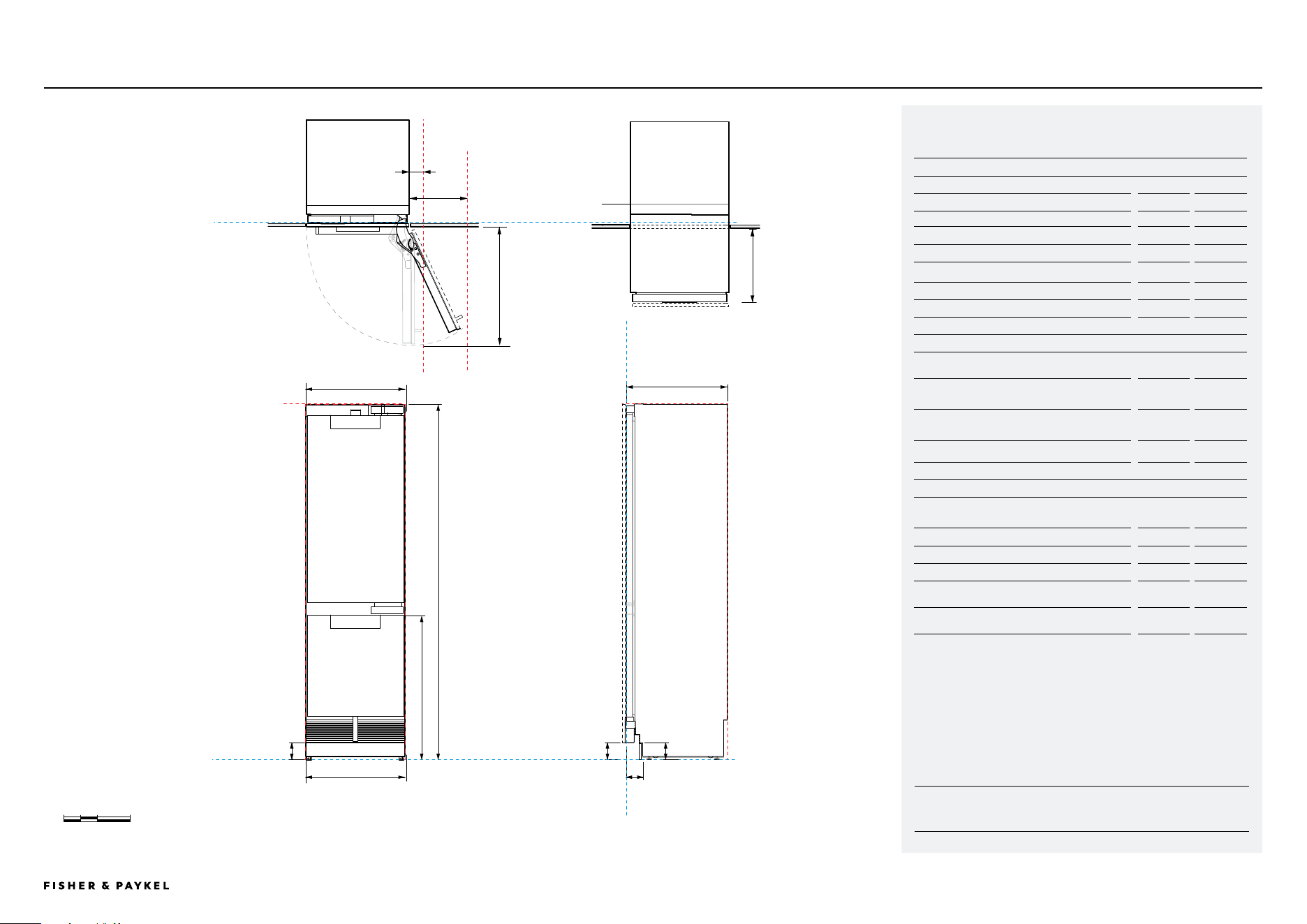
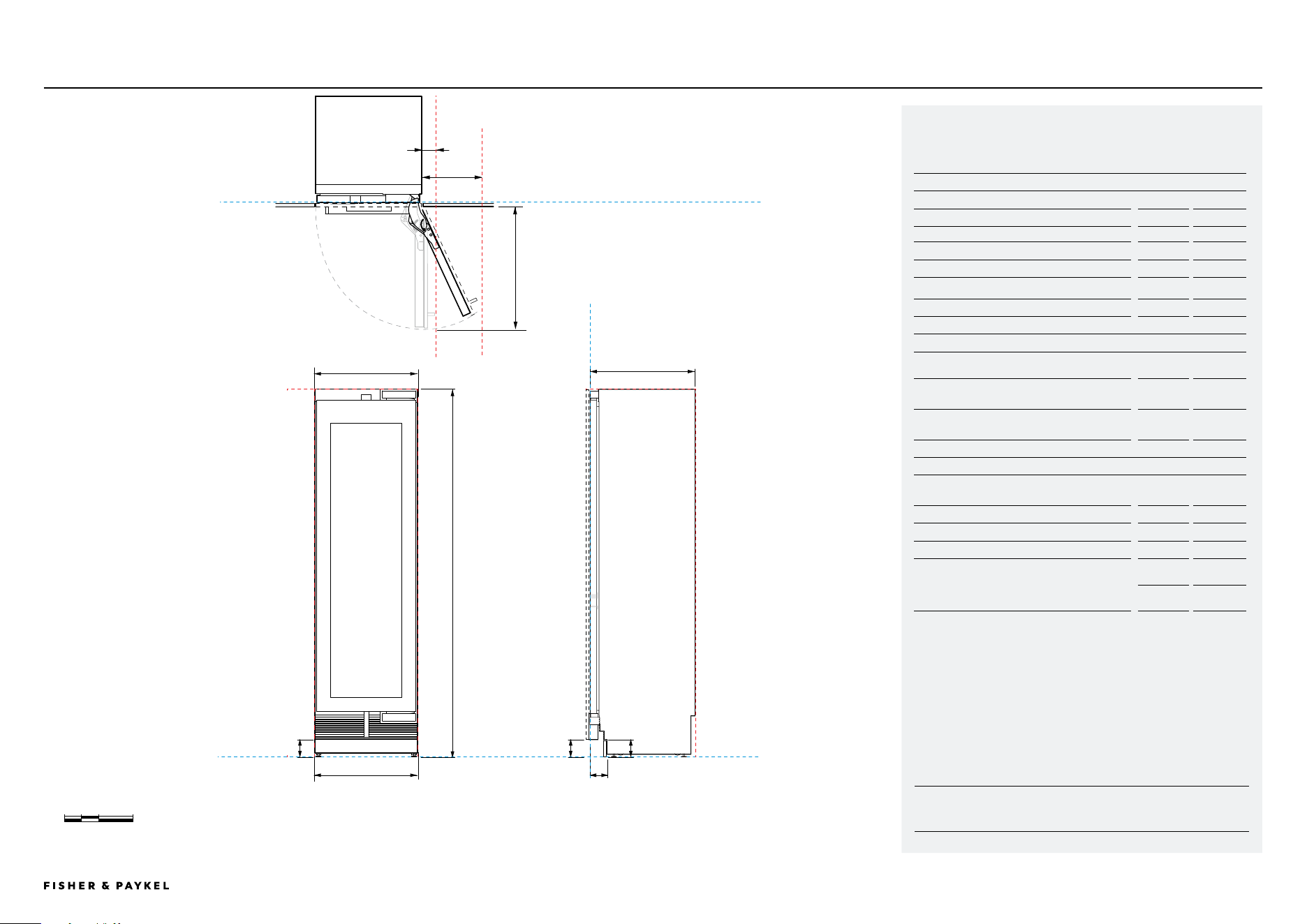
24" Refrigerator freezer
DATA SHEET | 24" REFRIGERATOR FREEZER RS2484WLUE1, RS2484WRUE1, RS2484WRUK1, RS2484WLUK1
INDICATES CABINETRY / PRODUCT DATUM -------------------------
INDICATES CABINETRY CLEARANCES --------------------------------
DATUM :
FLOOR (LEVEL)
0 100 200 400
millimetres
C
A
B
DD
I
H
J
PROFILE VIEWFRONT VIEW
PLAN VIEW
DATUM: FRONT OF CHASSIS
DATUM: FRONT OF CHASSIS
CLEARANCE: DOOR AT 115⁰
CLEARANCE: DOOR AT 90⁰
84"
23 ¾"
E
G
23 7/8"
K
Model no:
RS2484WLUE1, RS2484WLUK1, RS2484WRUE1, RS2484WRUK1
Product Dimensions
in
mm
a Overall height
84
2134
B Overall width
23 3/4
603
c Overall depth (excluding door panels)
24
610
D Floor to bottom of door
4
102
E Depth of toe kick (excluding panels)
2 7/8 - 4
73 - 102
F Height of toe kick
2 - 6
50 - 152
G Width of toe kick
23 7/8
606
H Height drawer (does not include panel)
34 1/4
870
Door/Drawer Opening Dimensions*
H Minimum door clearance** to adjacent wall*
(90° – reduced internal access)*
4 5/16
110
I Minimum door clearance** to adjacent wall*
(115° – full internal access)
14
356
J Depth of door (90° open) measured from
front of door
26
660
K Depth of drawer measured from front of door
15 3/4
400
Clearance Dimensions*
Minimum cabinetry gap clearance from edge of
door panel
1/8
3
Cavity overall height
84
2134
Cavity overall width (single)
24
610
Cavity overall width (dual)
48
1219
Minimum overall depth (shallow) of cavity when
services are located outside of cavity****
25
635
Minimum overall depth (deep) of cavity when
services are located at rear of cavity****
25 19/32
650
* Custom panels to be manufactured & fitted by cabinetmaker.
** 3 15/16" (100mm) tall stainless steel toe kick panel available. Adjust
the height of the door panel accordingly.
*** Door handle kit is available as an optional accessory.
****Assumes a door panel depth of 3/4" (19mm).
H
F
<< CONTENTS
IMPORTANT NOTE: Throughout this guide, dimensions may vary by ±2mm
(1/16''). Please read the Installation Guide for detailed information on
installing the product. For full installation instructions visit fisherpaykel.com
PAGE 1990003672C PLANNING GUIDE INTEGRATED REFRIGERATION 84" - VERSION 3 - SEPTEMBER 2024© FISHER & PAYKEL LIMITED 2024
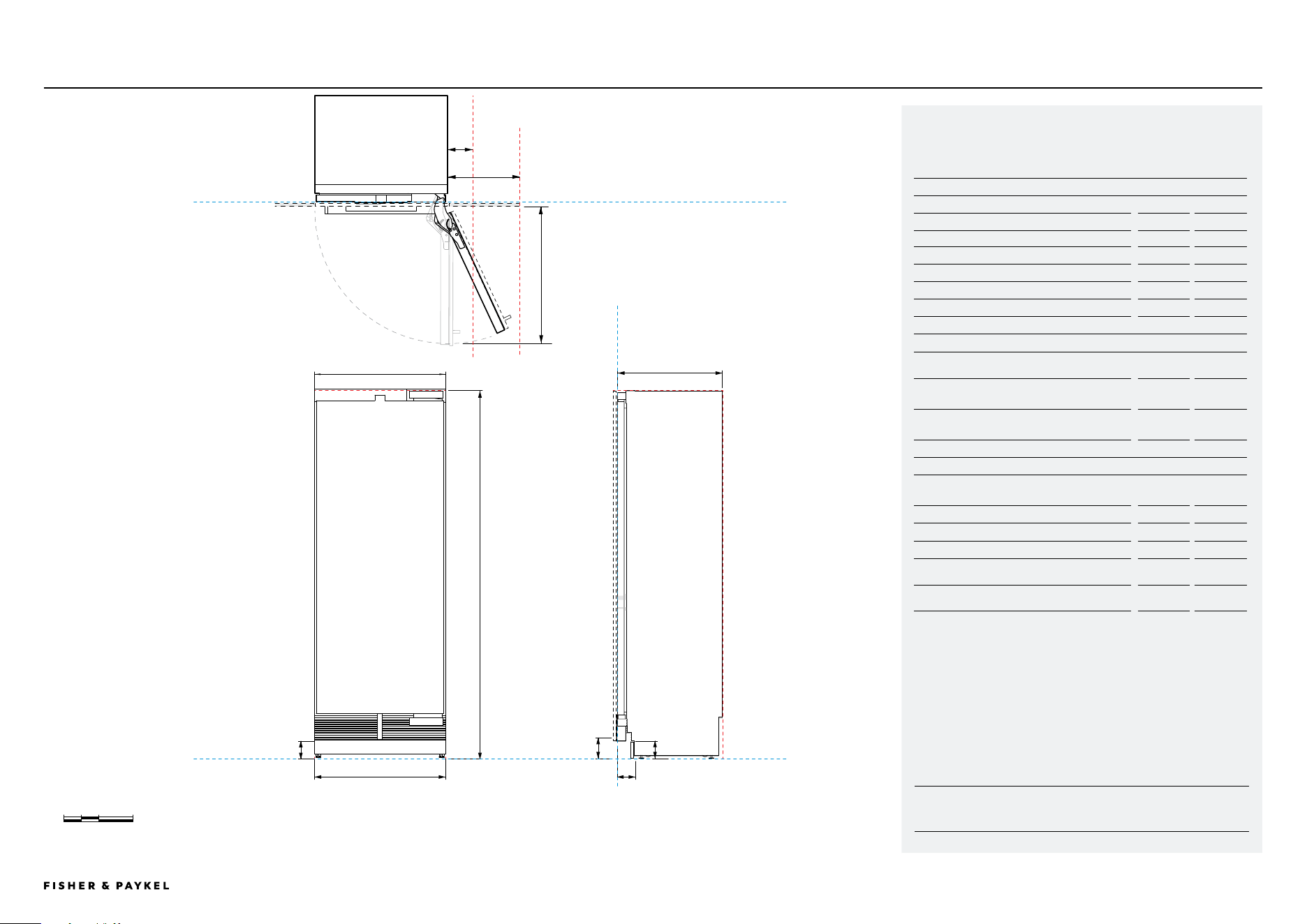
Model no:
RS2484VL2K1, RS2484VR2K1
Product Dimensions
in
mm
a Overall height
84 2134
B Overall width
23 3/4
603
c Overall depth (excluding door panels)
24 610
D Floor to bottom of door
4 102
E Depth of toe kick (excluding panels)
2 7/8 - 4 73 - 102
F Height of toe kick
2 - 6 50 - 152
G Width of toe kick
23 7/8 606
Door/Drawer Opening Dimensions*
H Minimum door clearance** to adjacent wall*
(90° – reduced internal access)*
4 5/16 110
I Minimum door clearance** to adjacent wall*
(115° – full internal access)
14 356
J Depth of door (90° open) measured from
front of door
15 3/4 660
Clearance Dimensions*
Minimum cabinetry gap
clearance from edge of
door panel
1/8
3
Cavity overall height
84
2134
Cavity overall width (single)
24
610
Cavity overall width (dual)
48
1219
Minimum overall depth (shallow) of cavity when
services are located outside of cavity****
Minimum overall depth (deep) of cavity when
services are located at rear of cavity****
25 635
25 19/32 650
* Custom panels to be manufactured & fitted by cabinetmaker
** 3 15/16" (100mm) tall stainless steel toe kick panel available. Adjust
the height of the door panel accordingly
*** Door handle kit is available as an optional accessory.
****Assumes a door panel depth of 3/4" (19mm).
24" Wine cabinet
DATA SHEET | 24" WINE CABINET RS2484VL2K1, RS2484VR2K1
INDICATES CABINETRY / PRODUCT DATUM -------------------------
INDICATES CABINETRY CLEARANCES --------------------------------
DATUM :
FLOOR (LEVEL)
0 100 200 400
millimetres
C
A
B
D
D
I
H
J
PROFILE VIEWFRONT VIEW
PLAN VIEW
DATUM: FRONT OF CHASSIS
DATUM: FRONT OF CHASSIS
CLEARANCE: DOOR AT 115⁰
CLEARANCE: DOOR AT 90⁰
84"
23 ¾"
E
G
23 7/8"
F
<< CONTENTS
IMPORTANT NOTE: Throughout this guide, dimensions may vary by ±2mm
(1/16''). Please read the Installation Guide for detailed information on
installing the product. For full installation instructions visit fisherpaykel.com
PAGE 2090003672C PLANNING GUIDE INTEGRATED REFRIGERATION 84" - VERSION 3 - SEPTEMBER 2024© FISHER & PAYKEL LIMITED 2024
Model no:
RS3084SRHE1, RS3084SLHE1, RS3084FRJE1, RS3084FLJE1,
RS3084SRK1, RS3084FLJK1
Product Dimensions
in
mm
a Overall height
84
2134
B Overall width
29 3/4
756
c Overall depth (excluding door panels)
24
610
D Floor to bottom of door
4
102
E Depth of toe kick (excluding panels)
2 7/8 - 4
73 - 102
F Height of toe kick
2 - 6
50 - 152
G Width of toe kick
29 7/8
759
Door/Drawer Opening Dimensions*
H Minimum door clearance** to adjacent wall*
(90° – reduced internal access)*
4 5/16
110
I Minimum door clearance** to adjacent wall*
(115° – full internal access)
16 1/2
419
J Depth of door (90° open) measured from
front of door
32
813
Clearance Dimensions*
Minimum cabinetry gap clearance from edge of
door panel
1/8
3
Cavity overall height
84
2134
Cavity overall width (single)
24
610
Cavity overall width (dual)
54
1525
Minimum overall depth (shallow) of cavity when
services are located outside of cavity****
25
635
Minimum overall depth (deep) of cavity when
services are located at rear of cavity****
25 19/32
650
* Custom panels to be manufactured & fitted by cabinetmaker.
** 3 15/16" (100mm) tall stainless steel toe kick panel available. Adjust
the height of the door panel accordingly.
*** Door handle kit is available as an optional accessory.
****Assumes a door panel depth of 3/4" (19mm).
30" Refrigeration and freezers
DATA SHEET | 30" REFRIGERATION
RS3084SRHE1, RS3084SLHE1, RS3084FRJE1, RS3084FLJE1, RS3084SRK1, RS3084FLJK1
INDICATES CABINETRY / PRODUCT DATUM -------------------------
INDICATES CABINETRY CLEARANCES --------------------------------
DATUM :
FLOOR (LEVEL)
0 100 200 400
millimetres
C
A
B
D
D
I
H
J
PROFILE VIEWFRONT VIEW
PLAN VIEW
DATUM: FRONT OF CHASSIS
DATUM: FRONT OF CHASSIS
CLEARANCE: DOOR AT 115⁰
CLEARANCE: DOOR AT 90⁰
84"
29 ¾"
E
G
29 7/8"
F
<< CONTENTS
IMPORTANT NOTE: Throughout this guide, dimensions may vary by ±2mm
(1/16''). Please read the Installation Guide for detailed information on
installing the product. For full installation instructions visit fisherpaykel.com
PAGE 2190003672C PLANNING GUIDE INTEGRATED REFRIGERATION 84" - VERSION 3 - SEPTEMBER 2024© FISHER & PAYKEL LIMITED 2024
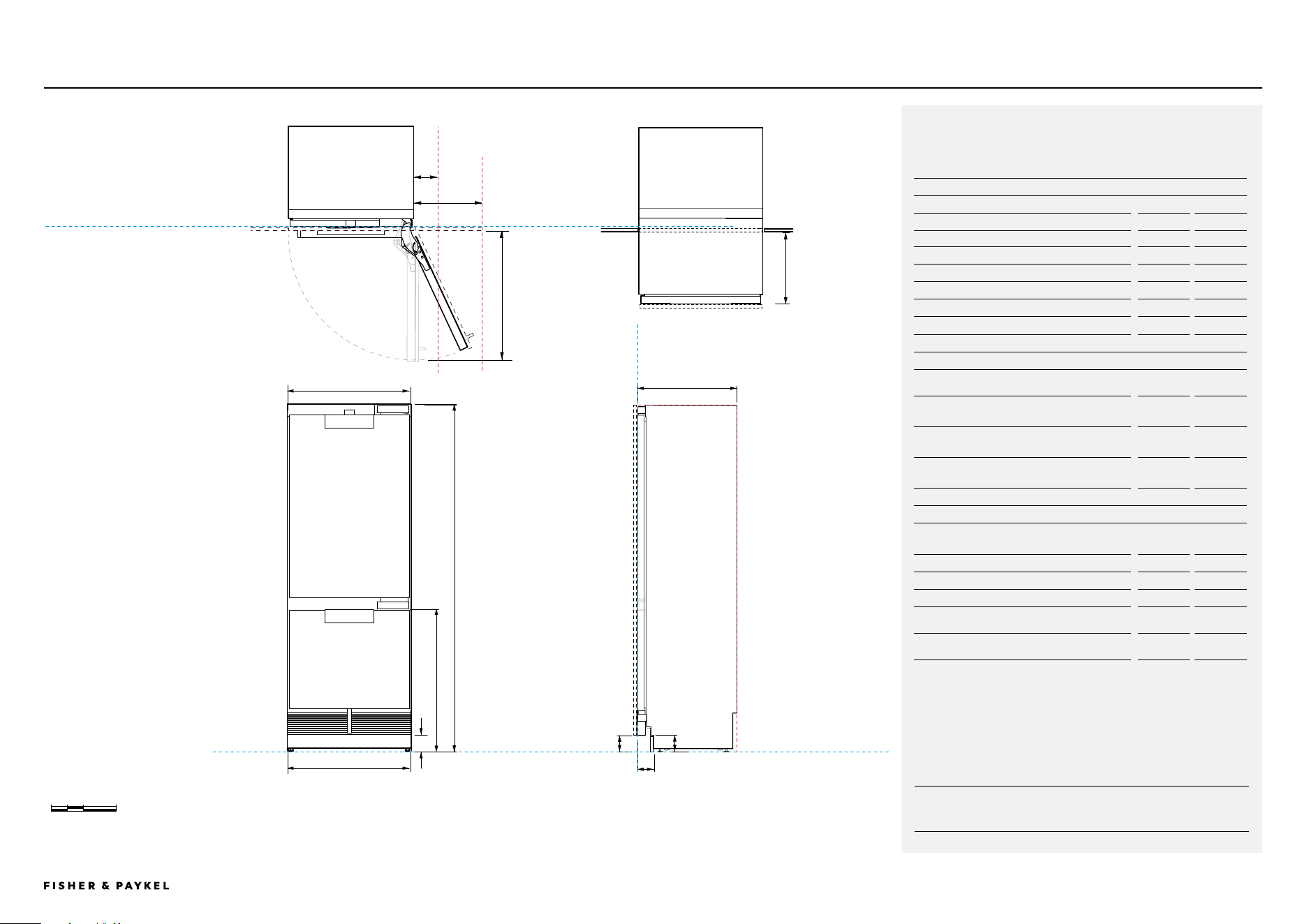
Model no:
RS3084WRUE1, RS3084WRUK1, RS3084WLUE1, RS3084WLUK1
Product Dimensions
in
mm
a Overall height
84
2134
B Overall width
29 3/4
756
c Overall depth (excluding door panels)
24
610
D Floor to bottom of door
4
102
E Depth of toe kick (excluding panels)
2 7/8 - 4
73 - 102
F Height of toe kick
2 - 6
50 - 152
G Width of toe kick
29 7/8
759
H Height of drawer (does not include panels)
34 1/4
870
Door/Drawer Opening Dimensions*
I Minimum door clearance** to adjacent wall*
(90° – reduced internal access)*
4 5/16
110
J Minimum door clearance** to adjacent wall*
(115° – full internal access)
16 1/2
419
K Depth of door (90° open) measured from
front of door
32
813
L Depth of drawer (open) measured from front
of drawer *
15 3/4
400
Clearance Dimensions*
Minimum cabinetry gap
clearance from edge of
door panel
1/8
3
Cavity overall height
84
2134
Cavity overall width (single)
30
762
Cavity overall width (dual)
54
1525
Minimum overall depth (shallow) of cavity when
services are located outside of cavity****
25
635
Minimum overall depth (deep) of cavity when
services are located at rear of cavity****
25 5/8
650
* Custom panels to be manufactured & fitted by cabinetmaker.
** 3 15/16" (100mm) tall stainless steel toe kick panel available. Adjust
the height of the door panel accordingly.
*** Door handle kit is available as an optional accessory.
****Assumes a door panel depth of 3/4" (19mm).
30" Refrigerator freezer
DATA SHEET | 30" REFRIGERATION/FREEZER RS3084WRUE1, RS3084WLUE1, RS3084WLUK1, RS3084WRUK1
INDICATES CABINETRY / PRODUCT DATUM -------------------------
INDICATES CABINETRY CLEARANCES --------------------------------
DATUM :
FLOOR (LEVEL)
0 100 200 400
millimetres
C
A
B
DD
J
I
K
PROFILE VIEWFRONT VIEW
PLAN VIEW
DATUM: FRONT OF CHASSIS
DATUM: FRONT OF CHASSIS
CLEARANCE: DOOR AT 115⁰
CLEARANCE: DOOR AT 90⁰
84"
29 ¾"
E
G
29 7/8"
L
H
F
<< CONTENTS
IMPORTANT NOTE: Throughout this guide, dimensions may vary by ±2mm
(1/16''). Please read the Installation Guide for detailed information on
installing the product. For full installation instructions visit fisherpaykel.com
PAGE 2290003672C PLANNING GUIDE INTEGRATED REFRIGERATION 84" - VERSION 3 - SEPTEMBER 2024© FISHER & PAYKEL LIMITED 2024
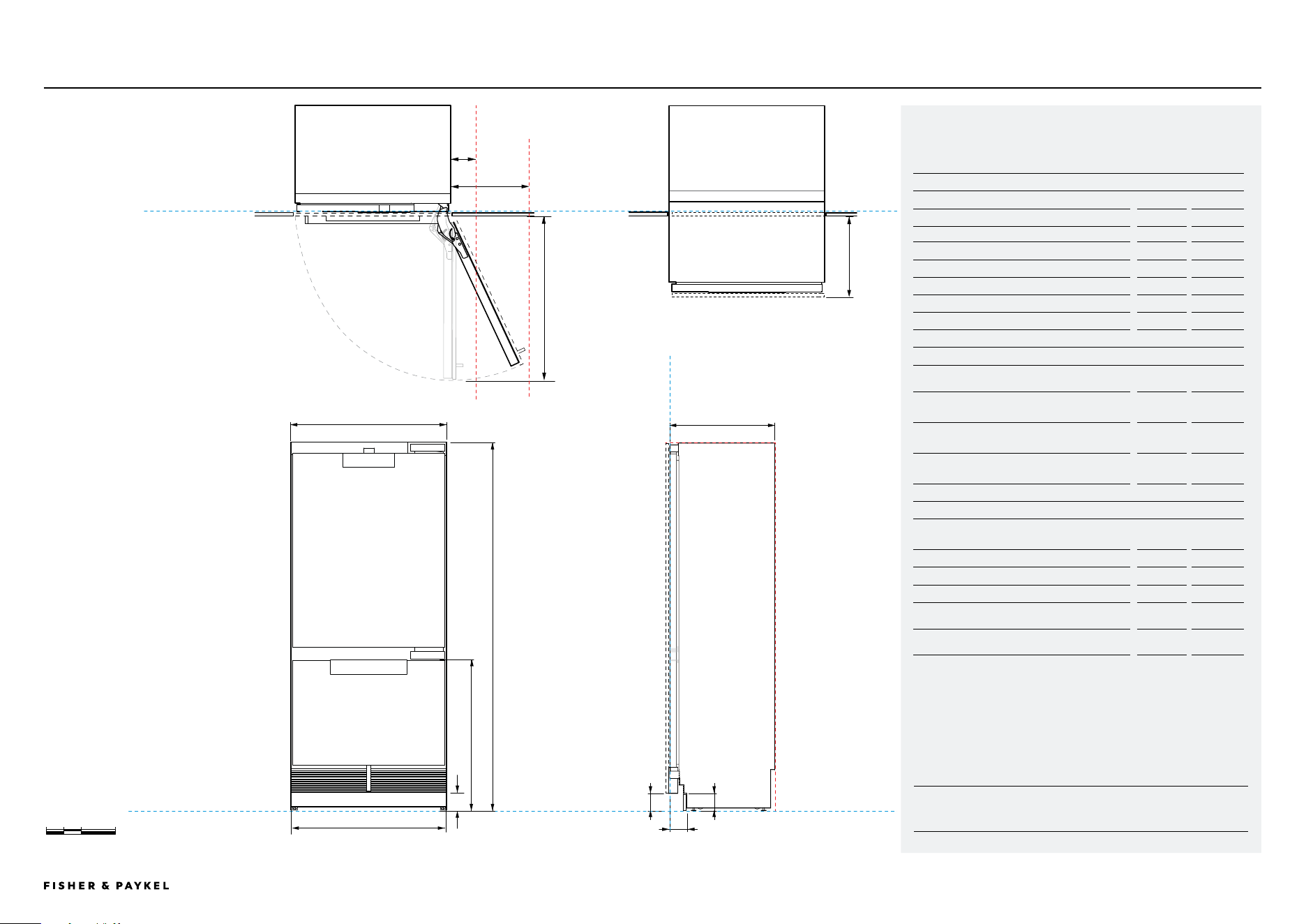
Model no:
RS3684WRUVE1, RS3684WLUVE1
Product Dimensions
in
mm
a Overall height
84
2134
B Overall width
35 3/4
908
c Overall depth (excluding door panels)
24
610
D Floor to bottom of door
4
102
E Depth of toe kick (excluding panels)
2 7/8 - 4
73 - 102
F Height of toe kick
2 - 6
50 - 152
G Width of toe kick
35 7/8
910
H Height drawer (does not include panel)
34 1/4
870
Door/Drawer Opening Dimensions*
I Minimum door clearance** to adjacent wall*
(90° – reduced internal access)*
4 5/16
110
J Minimum door clearance** to adjacent wall*
(115° – full internal access)
17 1/8
435
K Depth of door (90° open) measured from
front of door
38 1/16
967
L Depth of drawer (open) measured from front
of drawer *
15 3/4
400
Clearance Dimensions*
Minimum cabinetry gap
clearance from edge of
door panel
1/8
3
Cavity overall height
84
2134
Cavity overall width (single)
36
914
Cavity overall width (double)
72
1829
Minimum overall depth (shallow) of cavity when
services are located outside of cavity****
25
635
Minimum overall depth (deep) of cavity when
services are located at rear of cavity****
25 5/8
650
* Custom panels to be manufactured & fitted by cabinetmaker.
** 3 15/16" (100mm) tall stainless steel toe kick panel available. Adjust
the height of the door panel accordingly.
*** Door handle kit is available as an optional accessory.
****Assumes a door panel depth of 3/4" (19mm).
36" Refrigerator freezer
DATA SHEET | 36" REFRIGERATION RS3684WRUVE1, RS3684WLUVE1
INDICATES CABINETRY / PRODUCT DATUM -------------------------
INDICATES CABINETRY CLEARANCES --------------------------------
DATUM :
FLOOR (LEVEL)
0 100 200 400
millimetres
C
A
B
D
D
J
I
K
PROFILE VIEWFRONT VIEW
PLAN VIEW
DATUM: FRONT OF CHASSIS
DATUM: FRONT OF CHASSIS
CLEARANCE: DOOR AT 115⁰
CLEARANCE: DOOR AT 90⁰
84"
35 ¾"
E
G
35 7/8"
L
H
F
<< CONTENTS

© FISHER & PAYKEL LIMITED 2024 PAGE 2390003672C PLANNING GUIDE INTEGRATED REFRIGERATION 84" - VERSION 3 - SEPTEMBER 2024
PLANNING CONSIDERATIONS
The models shown in this Planning Guide may not be available in all markets and are subject to change at any time. Product specifications may vary from those shown. This Planning Guide should not be used as installation guidance for any product. Further information is required to safely and correctly install the
products featured here. Specific installation guidance will be available on our website fisherpaykel.com
PAGE 24PLANNING GUIDE INTEGRATED REFRIGERATION 84" - VERSION 3 - SEPTEMBER 202490003672C © FISHER & PAYKEL LIMITED 2024
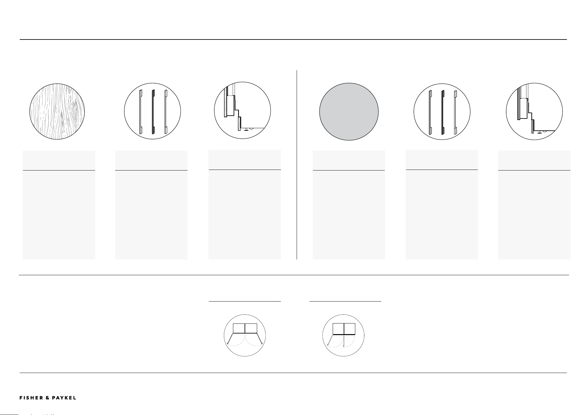
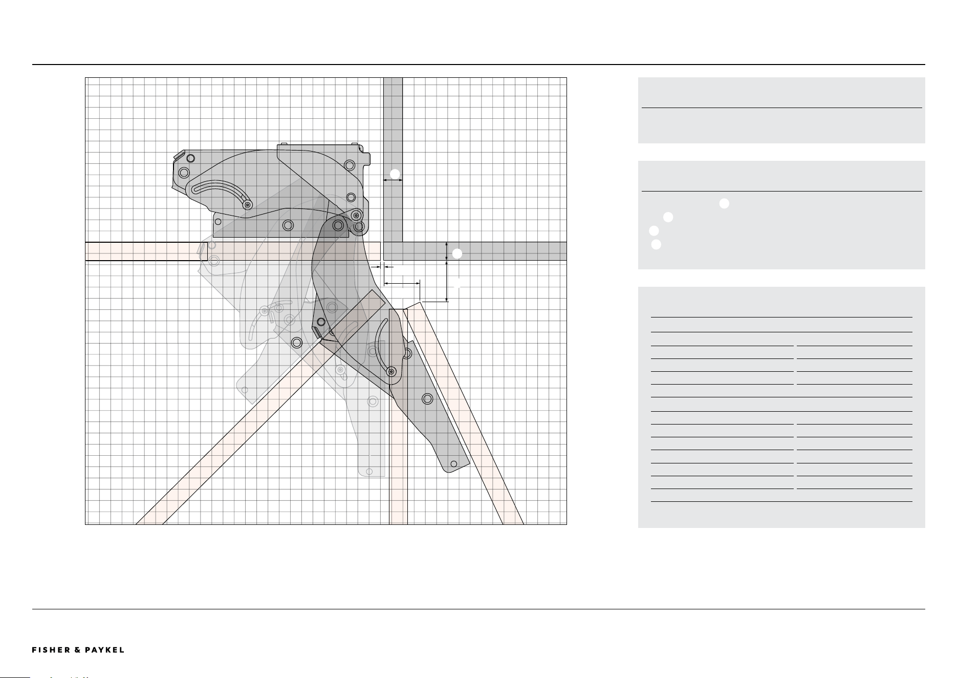
ALL MODELSPLANNING GUIDE | HINGE ARTICULATION
DOOR HINGE - HETTICH K05
Left handed hinge models are a mirrored
version of shown.
WEIGHT LIMITS
SINGLE PANEL MODELS MAXIMUM WEIGHT
RS1884 Max 44lbs (20kg)
RS2484 Max 55lbs (25kg)
RS2484V Wine cabinet Max 17.6lbs (8kg)
RS3084 Max 66lbs (30kg)
DOUBLE PANEL MODELS MAXIMUM WEIGHT
RS2484W Top panel Max 33lbs (15kg)
RS2484W Bottom panel Max 20lbs (9kg)
RS3084W Top panel Max 40lbs (18kg)
RS3084W Bottom panel Max 24lbs (11kg)
RS3684W Top panel Max 46lbs (21kg)
RS3684W Bottom panel Max 30lbs (13.5kg)
Note: Door weight includes weight of handle.
DOOR CLOSED
DOOR FULLY OPEN 115°
DOOR
90° OPEN
DOOR
45° OPEN
TOP VIEW
CUSTOM FRONT PANEL
a
Panel thickness: 3/4"(19mm).
b
Gap between door and adjacent cabinetry: Min 1/8"(3mm)
C
Gap between cabinet side and door at 115° open: 1 13/32"(36mm)
D
Gap between adjacent cabinet and door at 115°: 1 21/32"(42mm)
FRONT OF CABINETRY
a
a
b
1 SQUARE = 1/2" (12.7mm)
Hinge articulation
C
D
<< CONTENTS
The models shown in this Planning Guide may not be available in all markets and are subject to change at any time. Product specifications may vary from those shown. This Planning Guide should not be used as installation guidance for any product. Further information is required to safely and correctly install the
products featured here. Specific installation guidance will be available on our website fisherpaykel.com
PAGE 25PLANNING GUIDE INTEGRATED REFRIGERATION 84" - VERSION 3 - SEPTEMBER 202490003672C © FISHER & PAYKEL LIMITED 2024
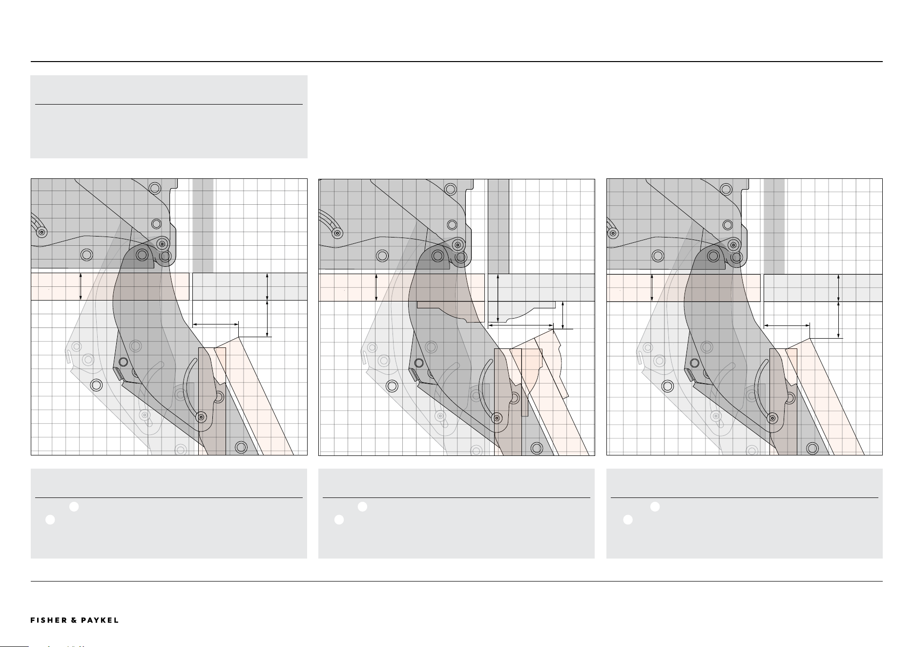
PANEL VARIATION EXAMPLESPLANNING GUIDE | HINGE ARTICULATION
1" OVERLAY DOOR PANEL
a
Door edge distance to cabinet side: 9/16" (14mm)
b
Gap between door corner and adjacent cabinetry: 15/32" (12mm)
NOTE: Panel widths must be adjusted.
A
B
1" DOOR PANEL WITH 3/4" FRAMING
a
Door edge distance to cabinet side : 1 3/38" (60mm)
b
Gap between door corner and adjacent cabinetry: 1 1/32" (26mm)
B
A
1" DOOR PANEL
a
Door edge distance to cabinet side : 1 21/32" (42mm)
b
Gap between door corner and adjacent cabinetry: 1 11/32" (34mm)
A
B
1 SQUARE = 1/2" (12.7mm)
SUPPORT
For additional design planning and installation support please contact
the Fisher & Paykel design support team.
designsupport@fisherpaykel.com
Panel variation examples
1" (25mm)
1" (25mm)
1 3/4" (46mm)
1" (25mm)
1" (25mm)
1" (25mm)
<< CONTENTS
The models shown in this Planning Guide may not be available in all markets and are subject to change at any time. Product specifications may vary from those shown. This Planning Guide should not be used as installation guidance for any product. Further information is required to safely and correctly install the
products featured here. Specific installation guidance will be available on our website fisherpaykel.com
PAGE 26PLANNING GUIDE INTEGRATED REFRIGERATION 84" - VERSION 3 - SEPTEMBER 202490003672C © FISHER & PAYKEL LIMITED 2024
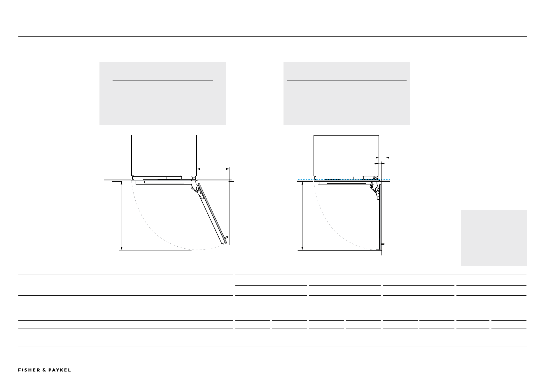
DOOR SWING
PLANNING GUIDE | DOOR SWING CLEARANCE
115° INTERNAL ACCESS
115° door opening - full internal access
Minimum dimensions shown are for a 1 5/8" handle
depth. Custom door panel and handle details need to
be taken into account
90° INTERNAL ACCESS
Use hinge limiting pin to restrict door opening to 90° where
necessary
Minimum dimensions shown are for a 1 5/8" handle depth.
Custom door panel and handle details need to be taken into
account
MINIMUM DOOR CLEARANCES
18" Models 24" Models 30" Models 36" Models
in mm in mm in mm in mm
A Door swing depth min 20 min 508 min 26 min 660 min 32 min 813 min 38 1/16 min 967
B Clearance for handle (at 900)* 5 5/16 min 110 5 5/16 min 110 5 5/16 min 110 5 5/16 min 110
C Clearance for handless (at 900)* 3/4 19** 3/4 19** 3/4 19** 3/4" 19**
D Clearance for handle (at 1150) min 11 1/2 min 292 min 14 min 356 min 17 1/8 min 435 min 14 min 356
* Limiting pins are required for a 900 door swing.
NOTE: Dimensions assume a panel depth of 19mm (3/4"). Thicker panels will require a wider gap between panels.
Door swing clearances
ADDITIONAL NOTES
Dimensions assume a panel
depth of 3/4" (19mm).
A
A
B
C
D
<< CONTENTS
The models shown in this Planning Guide may not be available in all markets and are subject to change at any time. Product specifications may vary from those shown. This Planning Guide should not be used as installation guidance for any product. Further information is required to safely and correctly install the
products featured here. Specific installation guidance will be available on our website fisherpaykel.com
PAGE 27PLANNING GUIDE INTEGRATED REFRIGERATION 84" - VERSION 3 - SEPTEMBER 202490003672C © FISHER & PAYKEL LIMITED 2024
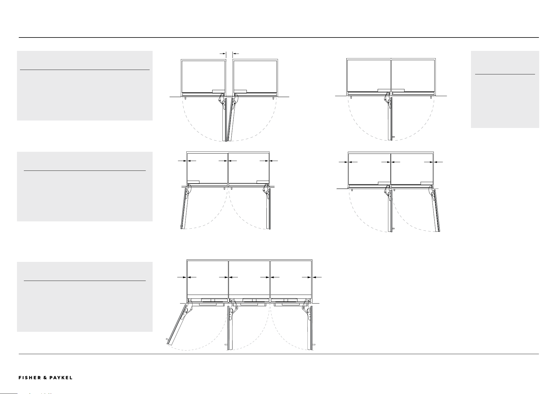
cc c
cc c
d
d d
d
HINGE TO HINGE
A Both doors open at the same time - requires space between
models
B Only allows a single door open at a time when there is a 1/8"
(3mm) gap between products
Min. 3 5/16" (100mm)
A B
DUAL INSTALLATION
c Stainless steel door panels (gaps equalized during
installation).
c Custom door panels - width of custom door panel increases
to maintain 1/8" (3mm) gap across multiple products
MULTIPLE INSTALLATION
d Stainless steel door panels (gaps equalized during
installation).
d Custom door panels - width of custom door panel increases
to maintain 1/8" (3mm) gap across multiple products
ADDITIONAL NOTES
Use hinge limiting pin to
restrict door opening to 90°
where necessary.
Dimensions assume a panel
depth of 3/4" (19mm).
DOOR OPENING AND PANEL GAPSPLANNING GUIDE | DOOR OPENING CLEARANCE
Door opening & gap clearances
<< CONTENTS

© FISHER & PAYKEL LIMITED 2024 PAGE 2890003672C PLANNING GUIDE INTEGRATED REFRIGERATION 84" - VERSION 3 - SEPTEMBER 2024
CAVITY PREPARATION
PAGE 2990003672C PLANNING GUIDE INTEGRATED REFRIGERATION 84" VERSION 3 - SEPTEMBER 2024 © FISHER & PAYKEL LIMITED 2024
SPECIFICATIONS | CAVITY DIMENSIONS SINGLE
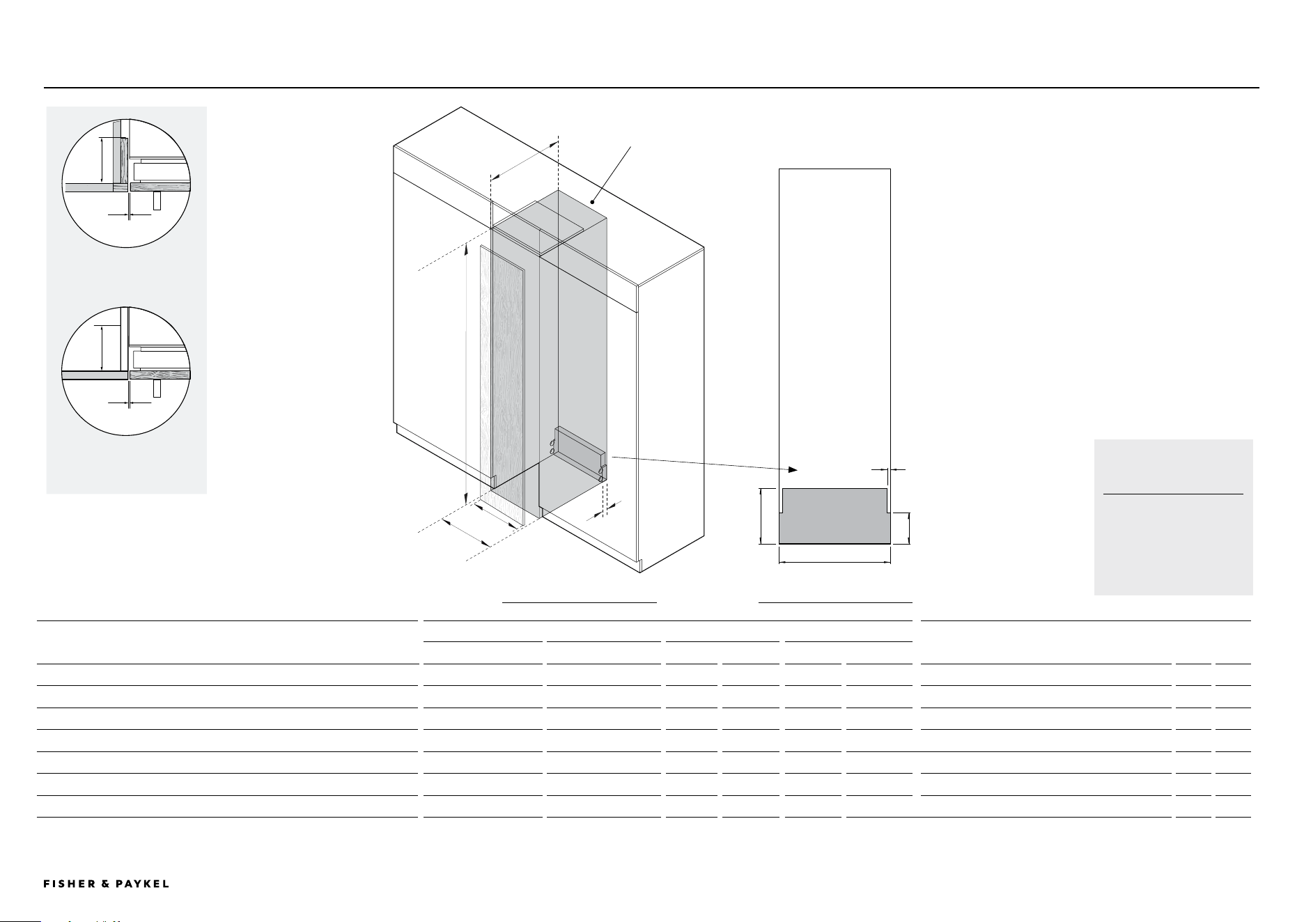
Single cavity dimensions
ADDITIONAL NOTES
Dimensions assume a panel
depth of 3/4" (19mm). Adjust
dimension C for thicker
panels.
FRAMED
CABINETRY
CAVITY DIMENSIONS
18" Model 24" Models
30" Models 36" Models
SUPPLY AREA
in mm in mm in mm in mm in mm
A Overall height of cavity
84 2134
84 2134 84 2134 84 2134
G Overall depth of supply area
9 229
B Overall width of cavity
18 457 24 610 30 762 36 914
H Overall height of supply area
1 25
C Minimum overall depth of cavity (services located at rear of cavity)
25 5/8 650 25 5/8 650 25 5/8 650 25 650
I Width of notch in supply area (both sides)
1/2 13
C Minimum overall depth of cavity (services located at outside of cavity)
25 635 25 635 25 635 25 635
J Height of sides of supply area (both sides)
5 127
D Custom door panel widths
17 3/4 451 23 3/4 603 29 3/4 756 35 3/4 908
E Minimum gap from edge of door panel to cabinetry
1/8 3 1/8 3 1/8 3 1/8 3
F Minimum required finished return
4 102 4 102 4 102 4 102
Assumes a door panel thickness of 3/4" (19mm).
UNFRAMED
CABINETRY
A
B
C
Alternative area
above cavity for
electrical connection
J
F
F
E
E
Electrical and
Plumbing supply area
H
G
I
B
D
ISO VIEW BACK OF CAVITY
<< CONTENTS
PAGE 3090003672C PLANNING GUIDE INTEGRATED REFRIGERATION 84" VERSION 3 - SEPTEMBER 2024 © FISHER & PAYKEL LIMITED 2024
SPECIFICATIONS | CAVITY DIMENSIONS DUAL AND TRIPLE
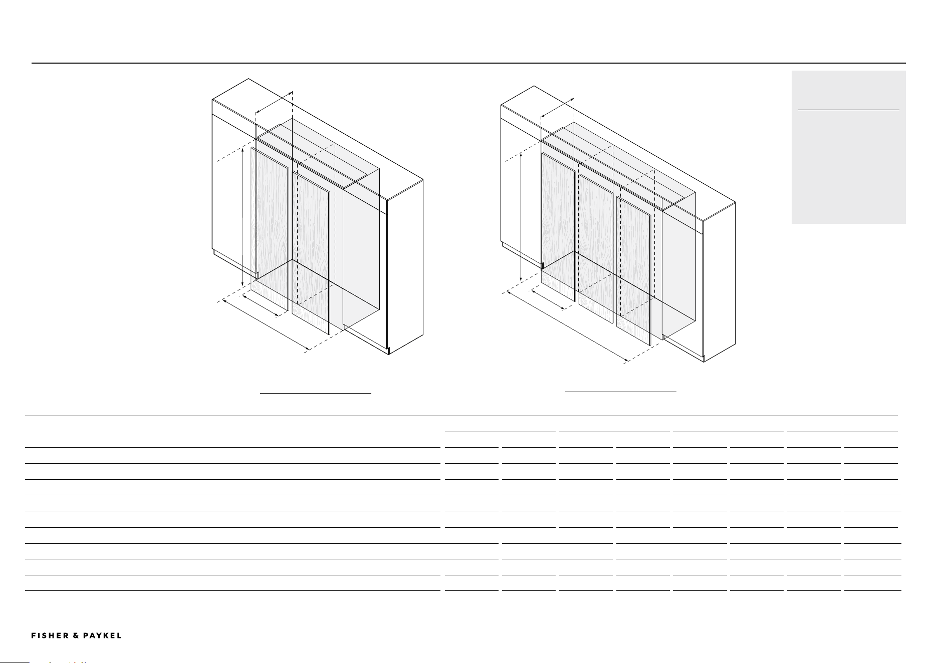
Dual and triple cavity dimensions
ADDITIONAL NOTES
Dimensions assume a panel
depth of 3/4" (19mm). Adjust
dimensions C or F for thicker
panels.
A maximum of three products
per cavity.
E
G
F
A
B
C
CAVITY DIMENSIONS DUAL INSTALL
18" Model 24" Models
30" Models 36" Models
in mm in mm in mm in mm
A Overall height of cavity
84 2134 84 2134 84 2134 84 2134
B Overall width of cavity
42 915 48 1219 54 1525 60 1829
C Minimum overall depth of cavity*
25 635 25 635 25 635 25 635
D Custom door panel widths
17 27/32 453 23 13/16 605 29 27/32 758 35 13/16 910
CAVITY DIMENSIONS TRIPLE INSTALL
E Overall height of cavity
84 2134 84 2134 84 2134 84 2134
F Overall width of cavity
66 1371 72 1827 78 2286 84 2742
G Minimum overall depth of cavity*
25 635 25 635 25 635 25 635
H Custom door panel widths
17 27/32 453 23 13/16 605 29 27/32 758 35 13/16 910
Assumes a door panel thickness of 3/4" (19mm).
DUAL INSTALL
TRIPLE INSTALL
D
H
<< CONTENTS
PAGE 3190003672C PLANNING GUIDE INTEGRATED REFRIGERATION 84" VERSION 3 - SEPTEMBER 2024 © FISHER & PAYKEL LIMITED 2024
SPECIFICATIONS | CAVITY DIMENSIONS MULTIPLE MODELS MULTIPLE MODEL CAVITY
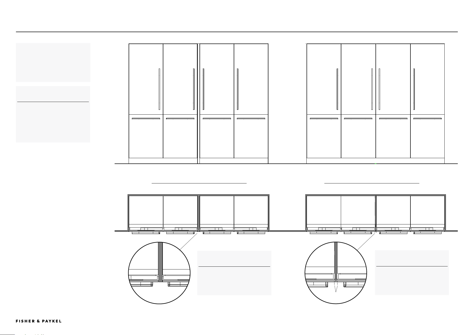
Multiple model cavity dimensions
The maximum amount of appliances
per cavity is three.
For more than three models a visual
or hidden spacer can be used.
SUPPORT
For additional design planning and
installation support please contact
the Fisher & Paykel design support
team
designsupport@fisherpaykel.com
DOUBLE CAVITY WITH VISUAL SPACER DOUBLE CAVITY WITH HIDDEN SPACER
HIDDEN SPACER
If overlaying panels to hide the
cavity spacer, allow for extra panel
width.
VISUAL SPACER
Standard panel widths can be used
with a visual cavity spacer.
Line of standard
panel width
<< CONTENTS
PAGE 3290003672C PLANNING GUIDE INTEGRATED REFRIGERATION 84" VERSION 3 - SEPTEMBER 2024 © FISHER & PAYKEL LIMITED 2024
SPECIFICATIONS | CAVITY DIMENSIONS MULTIPLE MODELS VARIED MODEL CAVITY
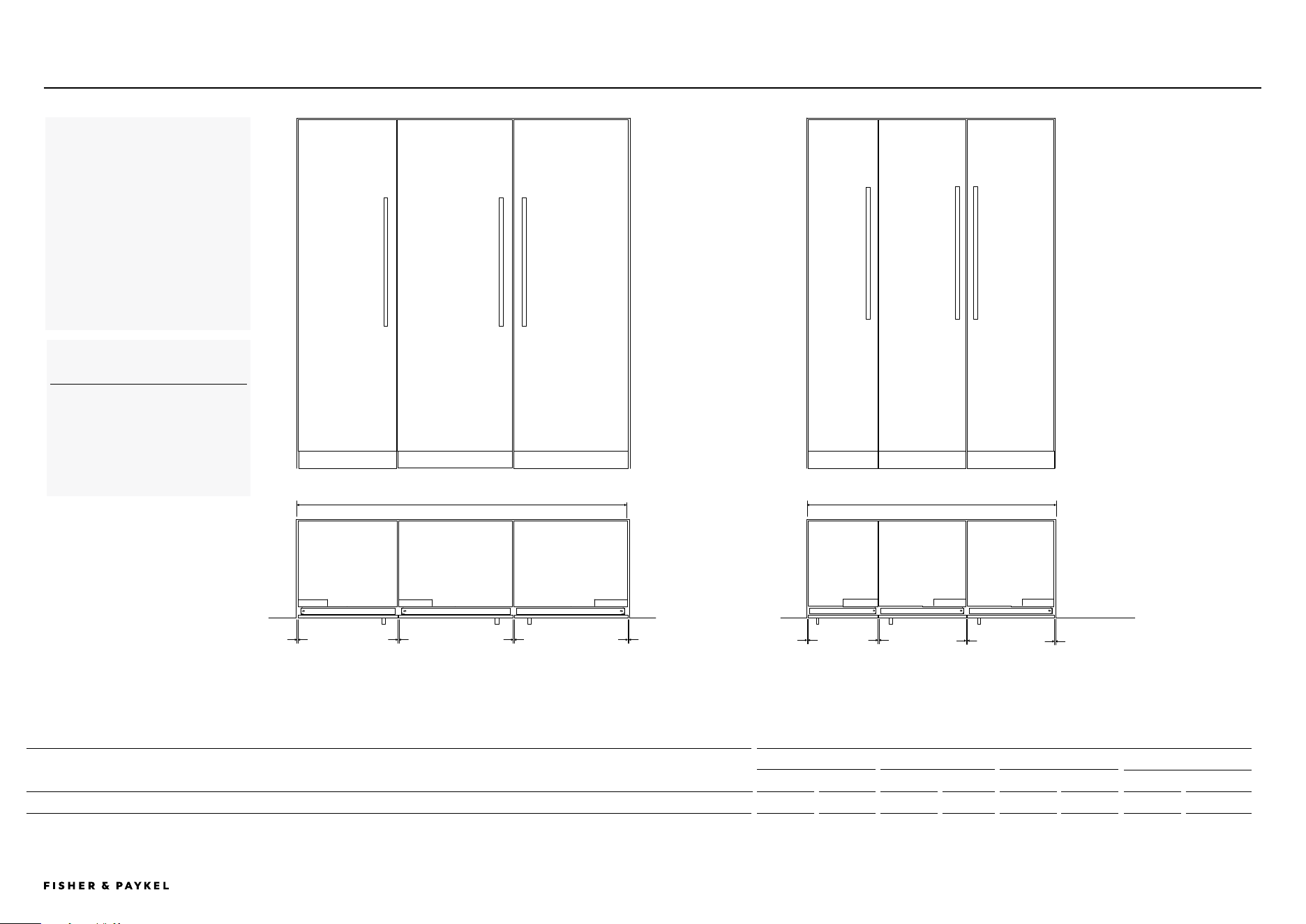
Varied model cavity dimensions
To calculate the total cavity width
for installing different models:
Add the widths of each panel for
dual or triple installations.
Add 1/8 inch (3mm) for every gap
between the appliances and the
gaps between the appliances and the
cabinet walls.
SUPPORT
For additional design planning and
installation support please contact
the Fisher & Paykel design support
team
designsupport@fisherpaykel.com
PANEL WIDTHS
18" Model 24" Models 30" Models 36"Models
in mm in mm in mm in mm
B Overall width of panel for dual or multiple install
17 27/32 453 23 15/16 605 29 27/32 758 35 13/16 910
Assumes a door panel thickness of 3/4" (19mm).
18" Freezer
Panel = 17 27/32"
24" Refrigerator
Panel = 23 13/16"
1/8"
3mm
1/8"
3mm
1/8"
3mm
24" Refrigerator
Panel = 23 13/16"
Cavity = 65 15/23" (1675mm)
1/8"
3mm
1/8"
3mm
1/8"
3mm
1/8"
3mm
1/8"
3mm
30" Refrigerator
Panel = 29 27/32"
36" Refrigerator Freezer
Panel = 35 13/16"
Cavity = 101 31/32" (2590mm)
36" Refrigerator Freezer
Panel = 35 13/16"
<< CONTENTS
PAGE 3390003672C PLANNING GUIDE INTEGRATED REFRIGERATION 84" VERSION 3 - SEPTEMBER 2024 © FISHER & PAYKEL LIMITED 2024
PRODUCT SPECIFICATIONS | Toe kick AND PANEL OPTIONS
2" toe kick
with extra
grill
2" HIGH TOE KICK WITH
EXTRA GRILL
6" TOE KICK - LOWER GRILL
REMOVED
100mm TK
2029mm panel
152mm TK
2029mm panel
100mm or 152 TK visiual
50
2080mm panel
100mm or 152 TK visiual
50
1978
mm panel
A
B
C
D
100mm TK
2029mm panel
152mm TK
2029mm panel
100mm or 152 TK visiual
50
2080mm panel
100mm or 152 TK visiual
50
1978
mm panel
A
B
C
D
Toe kick and panels - low and high options
Panel height 81 ⅞"
2" TOE KICK WITH EXTENDED PANEL OPTIONS
The standard toe kick height is 4" and the standard panel height is 79 7/8" (single door). For
refrigerator freezers the standard toe kick height is 4" and the drawer panel height is 30 3/8". For
single doors, a 2" high toe kick can be achieved by installing a 81 7/8" panel with an extra grill installed.
6" TOE KICK WITH SHORTENED PANEL OPTIONS
The standard toe kick height is 4" and the standard panel height is 79 7/8" (single door). For
refrigerator freezers the standard toe kick height is 4" and the drawer panel height is 30 3/8". For
single doors, a 6" toe kick with a 77 7/8" high panel can be achieved by removing the lower grill and
the airflow divider.
Panel height 77 ⅞"
LOW AND HIGH TOE KICKS
LOW TO FLOOR - PANEL & LOW Toe kick in mm
A Panel height - single door
81 7/8 2080
B Toe kick height
2 50
C Door height
49 3/8 1254
D Drawer height
32 3/8 822
HIGH ABOVE FLOOR - PANEL & HIGH Toe kick in mm
A Panel height - single door
77 7/8 1978
B Toe kick height
6 152
C Door height
49 3/8 1254
D Drawer height
28 3/8 721
<< CONTENTS

© FISHER & PAYKEL LIMITED 2024 PAGE 3490003672C PLANNING GUIDE INTEGRATED REFRIGERATION 84" - VERSION 3 - SEPTEMBER 2024
CUSTOM DOOR PANEL PREPARATION
The models shown in this Planning Guide may not be available in all markets and are subject to change at any time. Product specifications may vary from those shown. This Planning Guide should not be used as installation guidance for any product. Further information is required to safely and correctly install the
products featured here. Specific installation guidance will be available on our website fisherpaykel.com
PAGE 35PLANNING GUIDE INTEGRATED REFRIGERATION 84" - VERSION 3 - SEPTEMBER 202490003672C © FISHER & PAYKEL LIMITED 2024
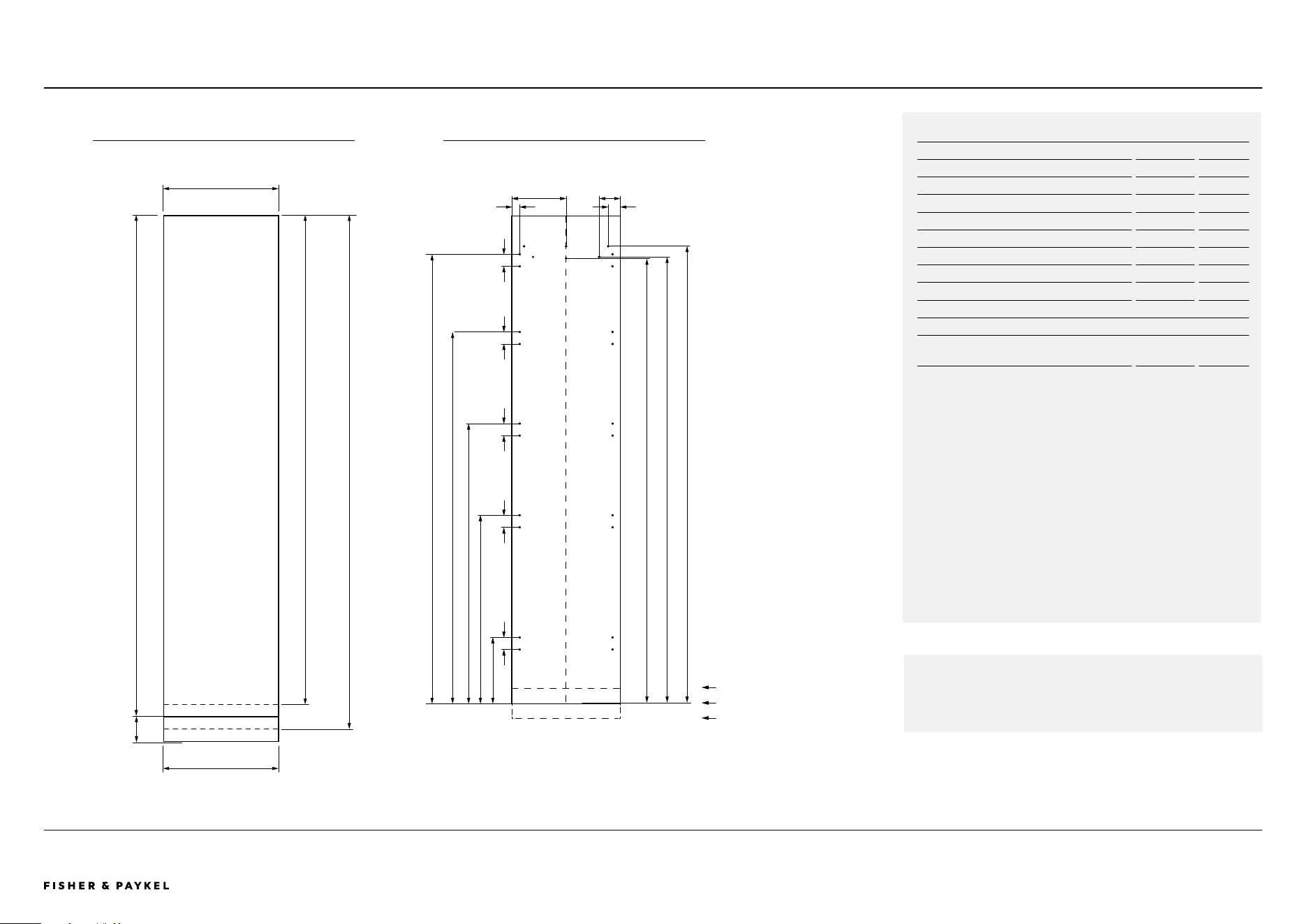
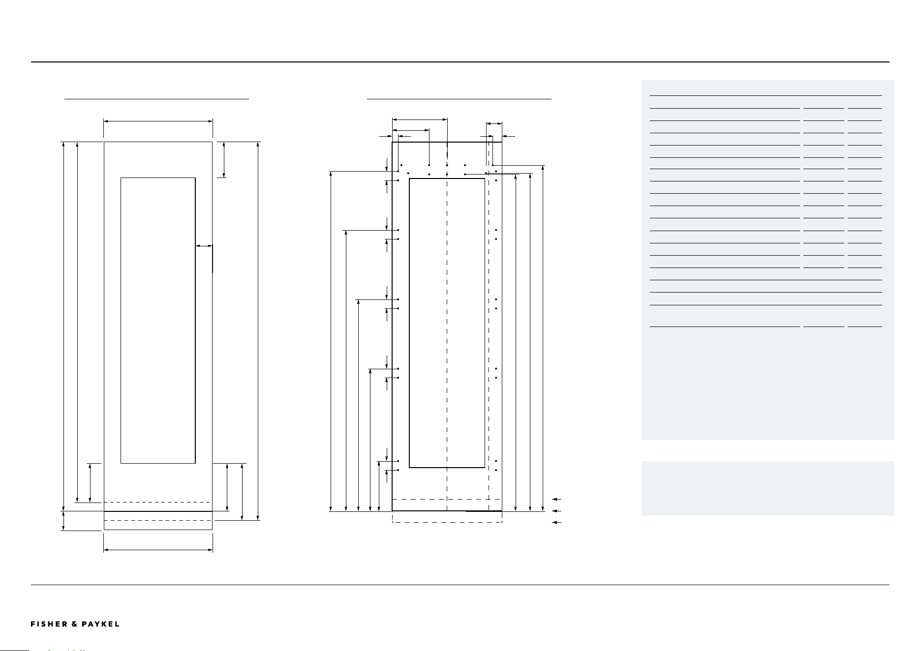
Model no: RS1884FLJE1, RS1884FLJK1
Custom Panel Dimensions
in
mm
A Height of door panel (standard 4" from floor)
79 7/8 2029
B Height of door panel (6" from floor)*
77 7/8 1978
C Height of door panel (2" from floor)*
81 7/8 2080
D Width of single panel
17 3/4 451
Width of dual/multiple panels 17 27/32 453
E Width of toe kick
17 7/8 454
F Toe kick height**
2 - 6 50 - 152
Panel thickness
min 3/4 min 19
Clearance Dimensions*
Minimum cabinetry gap
clearance from edge of
door panel
1/8
3
*Custom door panels, toe kick and handles to be manufactured / fitted by a
cabinet maker.
**Toe kick can height can vary depending on panel height and ventillation.
18" Freezer
SPECIFICATIONS | CUSTOM PANEL DETAILS RS1884FLJE1, RS1884FLJK1
10 7/8”
30 7/8”
45 7/8”
60 7/8”
73 19/32”
1 5/16”
8 29/32”
2”
3 15/32”
2” 2” 2” 2” 2”
72 29/32”
73 5/32”
74 7/8”
A
E
D
F
B C
PANEL DIMENSIONS MOUNTING HOLES
Dimensions apply for the preparation and installation of Custom
door panels.
Dwg and Dxf files of the panel preparation can be downloaded
from www.fisherpaykel.com
The thickness of the custom door panel can vary provided that the
screws do not penetrate beyond the full depth of the door panel.
Toe kick height 6"
Toe kick height 4"
Toe kick height 2"
18x Pilot holes recommended for bracket attachment.
(Do not penetrate front surface).
Do not place pilot holes for handle attachment in marked areas to avoid
clashing with panel attachment brackets
<< CONTENTS
The models shown in this Planning Guide may not be available in all markets and are subject to change at any time. Product specifications may vary from those shown. This Planning Guide should not be used as installation guidance for any product. Further information is required to safely and correctly install the
products featured here. Specific installation guidance will be available on our website fisherpaykel.com
PAGE 36PLANNING GUIDE INTEGRATED REFRIGERATION 84" - VERSION 3 - SEPTEMBER 202490003672C © FISHER & PAYKEL LIMITED 2024
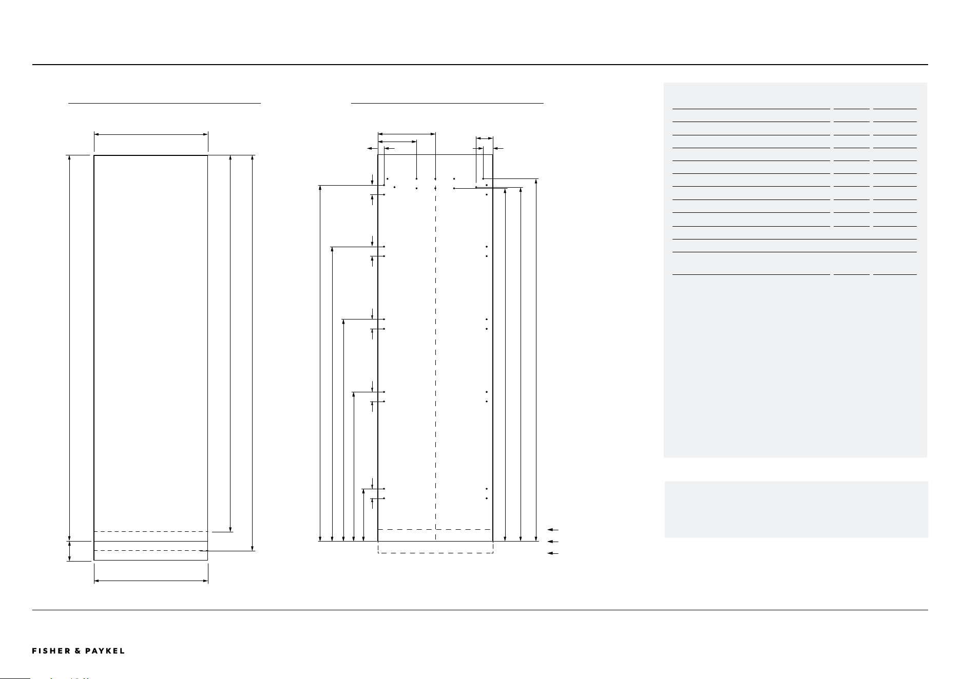
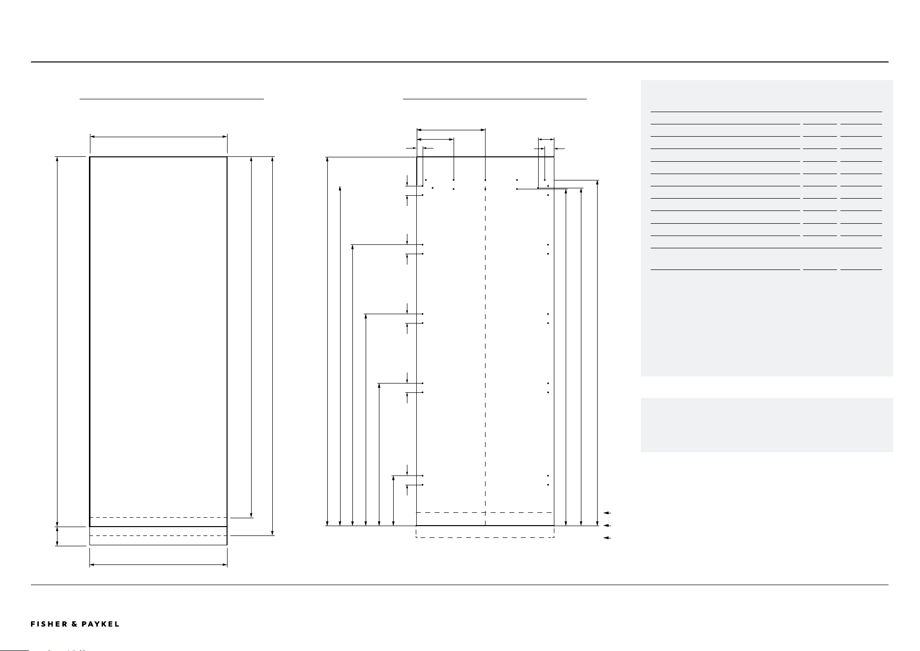
24" Single panel refrigerators and freezers
SPECIFICATIONS | CUSTOM PANEL DETAILS
RS2484SRHE1, RS2484SLHE1 RS2484FRJE1, RS2484FLJE1 RS2484SRK1, RS2484SRHK1, RS2484FLJK1
10 7/8”
30 7/8”
45 7/8”
60 7/8”
73 19/32”
8”
11 7/8”
1 5/16”
2”
3 15/32”
72 29/32”
73 5/32”
74 7/8”
2” 2” 2” 2” 2”
D
A
E
F
B C
PANEL DIMENSIONS MOUNTING HOLES
Dimensions apply for the preparation and installation of Custom
door panels.
Dwg and Dxf files of the panel preparation can be downloaded
from www.fisherpaykel.com
The thickness of the custom door panel can vary provided that the
screws do not penetrate beyond the full depth of the door panel.
Model no: RS2484SRHE1, RS2484SLHE1 RS2484FRJE1, RS2484FLJE1
RS2484SRK1, RS2484SRHK1, RS2484FLJK1
Custom Panel Dimensions in
mm
A Height of door panel (standard 4" from floor)*
79 7/8
2029
B Height of door panel (6" from floor)*
77 7/8
1978
C Height of door panel (2" from floor)*
81 7/8
2080
D Width of single panel
23 3/4
603
Width of dual/multiple panels 23 13/16
605
E Width of toe kick
23 7/8
606
F Toe kick height**
2 - 6
50 - 152
Panel thickness
min 3/4
min 19mm
Clearance Dimensions*
Minimum cabinetry gap
clearance from edge of
door panel
1/8
3
*Custom door panels, toe kick and handles to be manufactured / fitted by a
cabinet maker.
**Toe kick can height can vary depending on panel height and ventillation.
22x Pilot holes recommended for bracket attachment. (Do not penetrate
front surface).
Do not place pilot holes for handle attachment in marked areas to avoid
clashing with panel attachment brackets.
Toe kick height 6"
Toe kick height 4"
Toe kick height 2"
<< CONTENTS
The models shown in this Planning Guide may not be available in all markets and are subject to change at any time. Product specifications may vary from those shown. This Planning Guide should not be used as installation guidance for any product. Further information is required to safely and correctly install the
products featured here. Specific installation guidance will be available on our website fisherpaykel.com
PAGE 37PLANNING GUIDE INTEGRATED REFRIGERATION 84" - VERSION 3 - SEPTEMBER 202490003672C © FISHER & PAYKEL LIMITED 2024
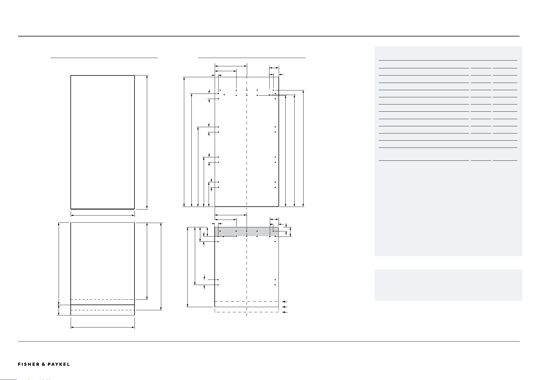
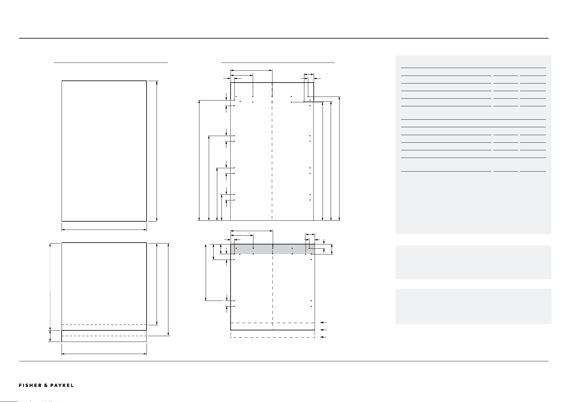
Model no: RS2484WRUE1, RS2484WRUK1, RS2484WLUE1, RS2484WLUK1
Custom Panel Dimensions
in
mm
A Height of door panel refrigerator*
49 3/8 1254
B Height of drawer panel (standard)
30 3/8 771
C Height of drawer panel (6" from floor)
28 3/8 721
D Height of drawer panel (2" from floor)
32 3/8 822
E Width of single panel
23 3/4 603
Width of dual/multiple panels 23 13/16 605
F Width of toe kick
23 7/8 606
G Toe kick height**
2 - 6 50 - 152
Panel thickness
min 3/4 min 19mm
Clearance Dimensions*
Minimum cabinetry gap
clearance from edge of
door panel
1/8
3
*Custom door panels, toe kick and handles to be manufactured / fitted by a
cabinet maker.
**Toe kick can height can vary depending on panel height and ventillation.
24" Refrigerator freezers
SPECIFICATIONS | CUSTOM PANEL DETAILS RS2484WRUE1, RS2484WRUK1, RS2484WLUE1, RS2484WLUK1
8”
44 3/8”
42 5/8”
1 5/16”
43 1/16”
30 11/32”
18 7/8”
7 3/8”
49 3/8”
11 7/8”
3 15/32”
2”
3 1/4”
2”1 5/16”
2”
2”
5 15/32”
21 31/32”
11 7/8”
8’
30 3/8”
3 19/32”
1 1/2”
3 15/32”
42 13/32”
2”
2”
2”
2”
F
A
B
E
G
C D
PANEL DIMENSIONS MOUNTING HOLES
Dimensions apply for the preparation and installation of Custom
door panels.
Dwg and Dxf files of the panel preparation can be downloaded
from www.fisherpaykel.com
The thickness of the custom door panel can vary provided that the
screws do not penetrate beyond the full depth of the door panel.
22x Pilot holes recommended for bracket attachment. (Do not penetrate
front surface).
Do not place pilot holes for handle attachment in marked areas to avoid
clashing with panel attachment brackets.
Toe kick height 6"
Toe kick height 4"
Toe kick height 2"
<< CONTENTS
The models shown in this Planning Guide may not be available in all markets and are subject to change at any time. Product specifications may vary from those shown. This Planning Guide should not be used as installation guidance for any product. Further information is required to safely and correctly install the
products featured here. Specific installation guidance will be available on our website fisherpaykel.com
PAGE 38PLANNING GUIDE INTEGRATED REFRIGERATION 84" - VERSION 3 - SEPTEMBER 202490003672C © FISHER & PAYKEL LIMITED 2024
Model no: RS2484VL2K1, RS2484VR2K1
Custom Panel Dimensions all models*
in
mm
A Height of door panel (standard 4" from floor)
79 7/8 2029
B Height of door panel (6" from floor)
77 7/8 1978
C Height of door panel (2" from floor)
81 7/8 2080
D Width of single panel
23 3/4 603
Width of dual/multiple panels 23 13/16 605
E Width of toe kick
23 7/8 606
F Width of side frames single install
3 11/16 94
Width of side frames dual install 3 3/4 95
G Height of top frame
7 7/8" - 11 7/8 200 - 302
H Height of lower frame
9
7/ 1 6
240
I Height of lower panel (6" from floor)
7 7/16 189
J Height of lower panel (2" from floor)
11
7/ 1 6
291
K Toe kick height**
1
7/ 1 6
50 - 152
Panel thickness
min 3/4 min 19mm
Clearance Dimensions*
Minimum cabinetry gap
clearance from edge of
door panel
1/8
3
*Custom door panels, toe kick and handles to be manufactured / fitted by a
cabinet maker.
**Toe kick can height can vary depending on panel height and ventillation.
24" Wine cabinet
SPECIFICATIONS | CUSTOM PANEL DETAILS RS2484VL2K1, RS2484VR2K1
10 7/8”
30 7/8”
45 7/8”
60 7/8”
73 19/32”
1 5/16”
8”
11 7/8”
3 15/32”
2”
72 29/32”
73 5/32”
74 7/8”
2”2”2”2”
2”
F
K
A
D
G
E
H
B
C
I
J
PANEL DIMENSIONS MOUNTING HOLES
Dwg and Dxf files of the panel preparation can be downloaded
from www.fisherpaykel.com
The thickness of the custom door panel can vary provided that the
screws do not penetrate beyond the full depth of the door panel.
22x Pilot holes recommended for bracket attachment. (Do not penetrate
front surface).
Do not place pilot holes for handle attachment in marked areas to avoid
clashing with panel attachment brackets.
Toe kick height 6"
Toe kick height 4"
Toe kick height 2"
<< CONTENTS
The models shown in this Planning Guide may not be available in all markets and are subject to change at any time. Product specifications may vary from those shown. This Planning Guide should not be used as installation guidance for any product. Further information is required to safely and correctly install the
products featured here. Specific installation guidance will be available on our website fisherpaykel.com
PAGE 39PLANNING GUIDE INTEGRATED REFRIGERATION 84" - VERSION 3 - SEPTEMBER 202490003672C © FISHER & PAYKEL LIMITED 2024
Model no: RS3084SRHE1, RS3084SLHE1, RS3084FRJE1, RS3084FLJE1,
RS3084SRK1, RS3084FLJK1
Custom Panel Dimensions all models*
in
mm
A Height of door panel (standard 4" from floor)
79 7/8
2029
B Height of door panel (6" from floor)
77 7/8
1978
C Height of door panel (2" from floor)
81 7/8
2080
D Width of single panel
29 3/4
756
Width of dual/multiple panels 29 27/32
758
E Width of toe kick
29 7/8
759
F Toe kick height**
2 - 6
50 - 152
Panel thickness
min 3/4
min 19mm
Clearance Dimensions*
Minimum cabinetry gap
clearance from edge of
door panel
1/8
3
*Custom door panels, toe kick and handles to be manufactured / fitted by a
cabinet maker.
**Toe kick can height can vary depending on panel height and ventillation.
30" Single panel refrigerators and freezers
SPECIFICATIONS | CUSTOM PANEL DETAILS
10 7/8”
30 7/8”
45 7/8”
60 7/8”
73 19/32”
79 7/8”
1 5/16”
8”
14 7/8”
72 29/32”
73 5/32”
74 7/8”
2”
3 15/32”
2” 2” 2” 2”
2”
A
E
D
RS3084SRHE1, RS3084SLHE1, RS3084FRJE1, RS3084FLJE1, RS3084SRK1, RS3084FLJK1
Dwg and Dxf files of the panel preparation can be downloaded
from www.fisherpaykel.com
The thickness of the custom door panel can vary provided that the
screws do not penetrate beyond the full depth of the door panel.
B C
F
PANEL DIMENSIONS MOUNTING HOLES
22x Pilot holes recommended for bracket attachment. (Do not penetrate
front surface).
Do not place pilot holes for handle attachment in marked areas to avoid
clashing with panel attachment brackets.
Toe kick height 6"
Toe kick height 4"
Toe kick height 2"
<< CONTENTS
The models shown in this Planning Guide may not be available in all markets and are subject to change at any time. Product specifications may vary from those shown. This Planning Guide should not be used as installation guidance for any product. Further information is required to safely and correctly install the
products featured here. Specific installation guidance will be available on our website fisherpaykel.com
PAGE 40PLANNING GUIDE INTEGRATED REFRIGERATION 84" - VERSION 3 - SEPTEMBER 202490003672C © FISHER & PAYKEL LIMITED 2024
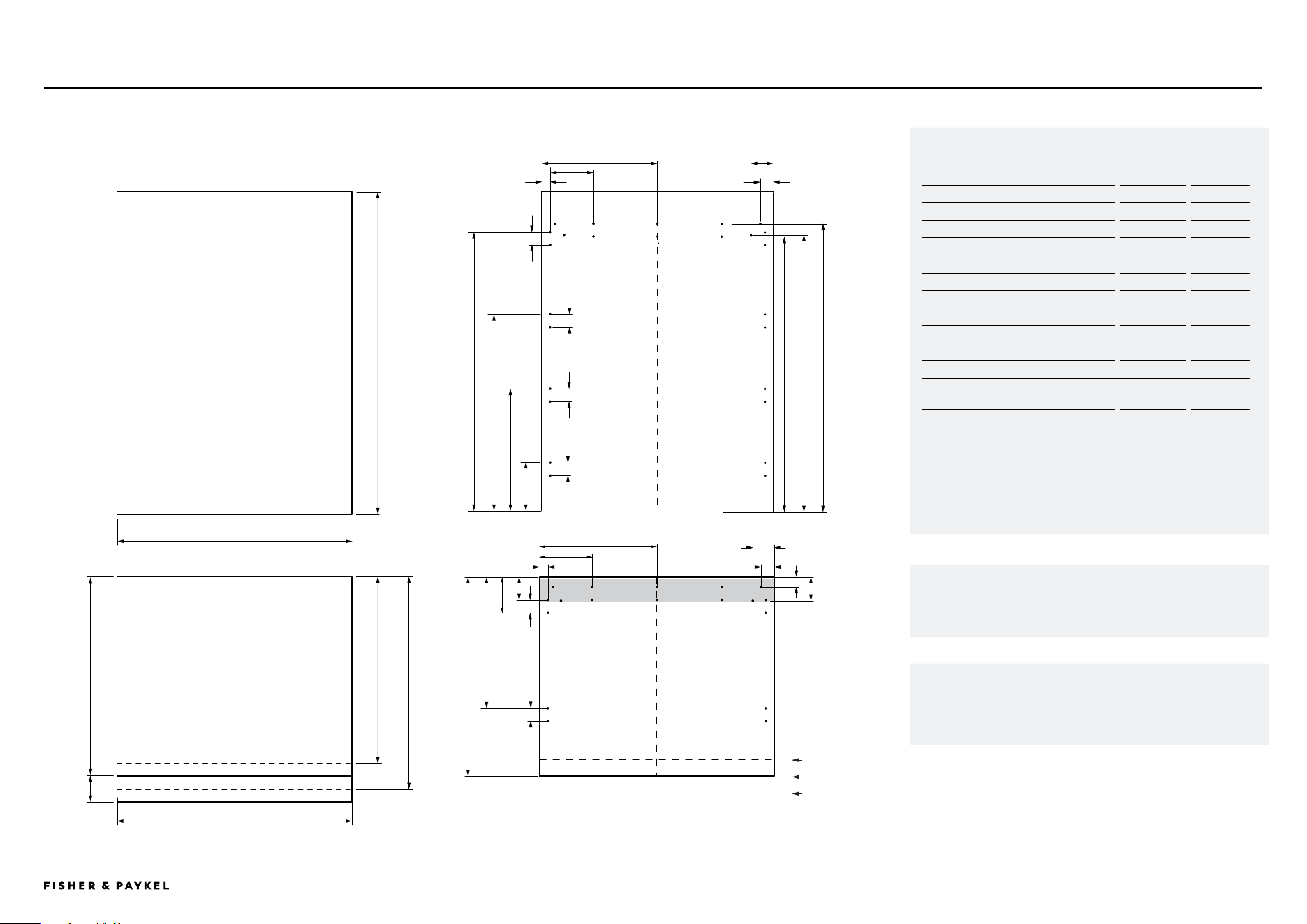
Model no: RS3084WLUE1, RS3084WLUK1, RS3084WRUE1, RS3084WRUK1
Custom Panel Dimensions*
in
mm
A Height of door panel refrigerator
49 3/8
1254
B Height of drawer panel (standard)
30 3/8
771
C Height of drawer panel (6" from floor)
28 3/8
721
D Height of drawer panel (2" from floor)
32 3/8
822
E Width of single panel
29 3/4
756
Width of dual/multiple panels 29 27/32
758
F Width of toe kick
29 7/8
759
G Toe kick height**
2 - 6
50 - 152
Panel thickness
min 3/4
min 19mm
Clearance Dimensions*
Minimum cabinetry gap
clearance from edge of
door panel
1/8
3
*Custom door panels, toe kick and handles to be manufactured / fitted by a
cabinet maker.
**Toe kick can height can vary depending on panel height and ventillation.
30" Refrigerator freezers
SPECIFICATIONS | CUSTOM PANEL DETAILS
A
F
G
E
RS3084WLUE1, RS3084WLUE1, RS3084WRUE1, RS3084WRUK1
Dwg and Dxf files of the panel preparation can be downloaded
from www.fisherpaykel.com
The thickness of the custom door panel can vary provided that the
screws do not penetrate beyond the full depth of the door panel.
B
C D
PANEL DIMENSIONS MOUNTING HOLES
2”
7 3/8”
18 29/32”
30 3/8”
43 1/8”
1 5/16”
8”
14 7/8”
2”
3 15/32”
42 5/8”
44 3/8”
2” 2” 2”
3 1/2”
5 15/32”
20”
1 1/2”
3 19/32”
1 5/16”
8’
14 7/8”
2”
3 1/4”
2”
2”
42 13/32”
10x Pilot holes recommended for bracket attachment. (Do not penetrate
front surface).
Ensure handle is mounted 65mm from edge of panel to the centre — this
will avoid interference with bracket.
Cut-outs in the hanging bracket are applicable for Fisher and Paykel
handles only.
If locating a custom handle in the shaded area shown above, ensure
handle screw headsare countersunk into the back of the door panel to
avoid interference with the hanging bracket.
Toe kick height 6"
Toe kick height 4"
Toe kick height 2"
<< CONTENTS
The models shown in this Planning Guide may not be available in all markets and are subject to change at any time. Product specifications may vary from those shown. This Planning Guide should not be used as installation guidance for any product. Further information is required to safely and correctly install the
products featured here. Specific installation guidance will be available on our website fisherpaykel.com
PAGE 41PLANNING GUIDE INTEGRATED REFRIGERATION 84" - VERSION 3 - SEPTEMBER 202490003672C © FISHER & PAYKEL LIMITED 2024
Model no: RS3684WRUVE1, RS3684WLUVE1
Custom Panel Dimensions*
in
mm
A Height of door panel refrigerator
49 3/8
1254
B Height of drawer panel (standard)
30 3/8
771
C Height of drawer panel (6" from floor)
28 3/8
721
D Height of drawer panel (2" from floor)
32 3/8
822
E Width of single panel
35 3/4
908
Width of dual/multiple panels 35 13/16
910
F Width of toe kick
35 7/8
911
G Toe kick height**
2 - 6
50 - 152
Panel thickness
min 3/4
min 19mm
Clearance Dimensions*
Minimum cabinetry gap
clearance from edge
of door panel
1/8
3
*Custom door panels, toe kick and handles to be manufactured / fitted by a
cabinet maker.
**Toe kick can height can vary depending on panel height and ventillation.
36" Refrigerator freezer
SPECIFICATIONS | CUSTOM PANEL DETAILS
A
F
B
E
RS3684WRUVE1, RS3684WLUVE1
Dwg and Dxf files of the panel preparation can be downloaded
from www.fisherpaykel.com
The thickness of the custom door panel can vary provided that the screws
do not penetrate beyond the full depth of the door panel.
G
C D
10x Pilot holes recommended for bracket attachment.
(Do not penetrate front surface).
Ensure handle is mounted 65mm from edge of panel to the
centre — this will avoid interference with bracket.
Cut-outs in the hanging bracket are applicable for Fisher and Paykel
handles only.
If locating a custom handle in the shaded area shown above, ensure
handle screw headsare countersunk into the back of the door panel to
avoid interference with the hanging bracket.
PANEL DIMENSIONS MOUNTING HOLES
Toe kick height 6"
Toe kick height 4"
Toe kick height 2"
7 3/8”
18 26/32”
30 3/8”
43 1/8”
1 5/16”
8”
17 7/8”
2”
3 15/32”
42 13/32”
42 5/8”
44 3/8”
3 1/2”
5 15/32”
20”
30 3/8”
1 1/2”
3 19/32”
1 5/16”
8”
17 7/8”
2”
3 1/4”
2” 2”
2”
2”
2”
2”
<< CONTENTS

© FISHER & PAYKEL LIMITED 2024 PAGE 4290003672C PLANNING GUIDE INTEGRATED REFRIGERATION 84" - VERSION 3 - SEPTEMBER 2024
SERVICES
IMPORTANT NOTE: Throughout this guide, dimensions may vary by ±2mm
(1/16''). Please read the Installation Guide for detailed information on
installing the product. For full installation instructions visit fisherpaykel.com
PAGE 4390003672C PLANNING GUIDE INTEGRATED REFRIGERATION 84" - VERSION 3 - SEPTEMBER 2024© FISHER & PAYKEL LIMITED 2024
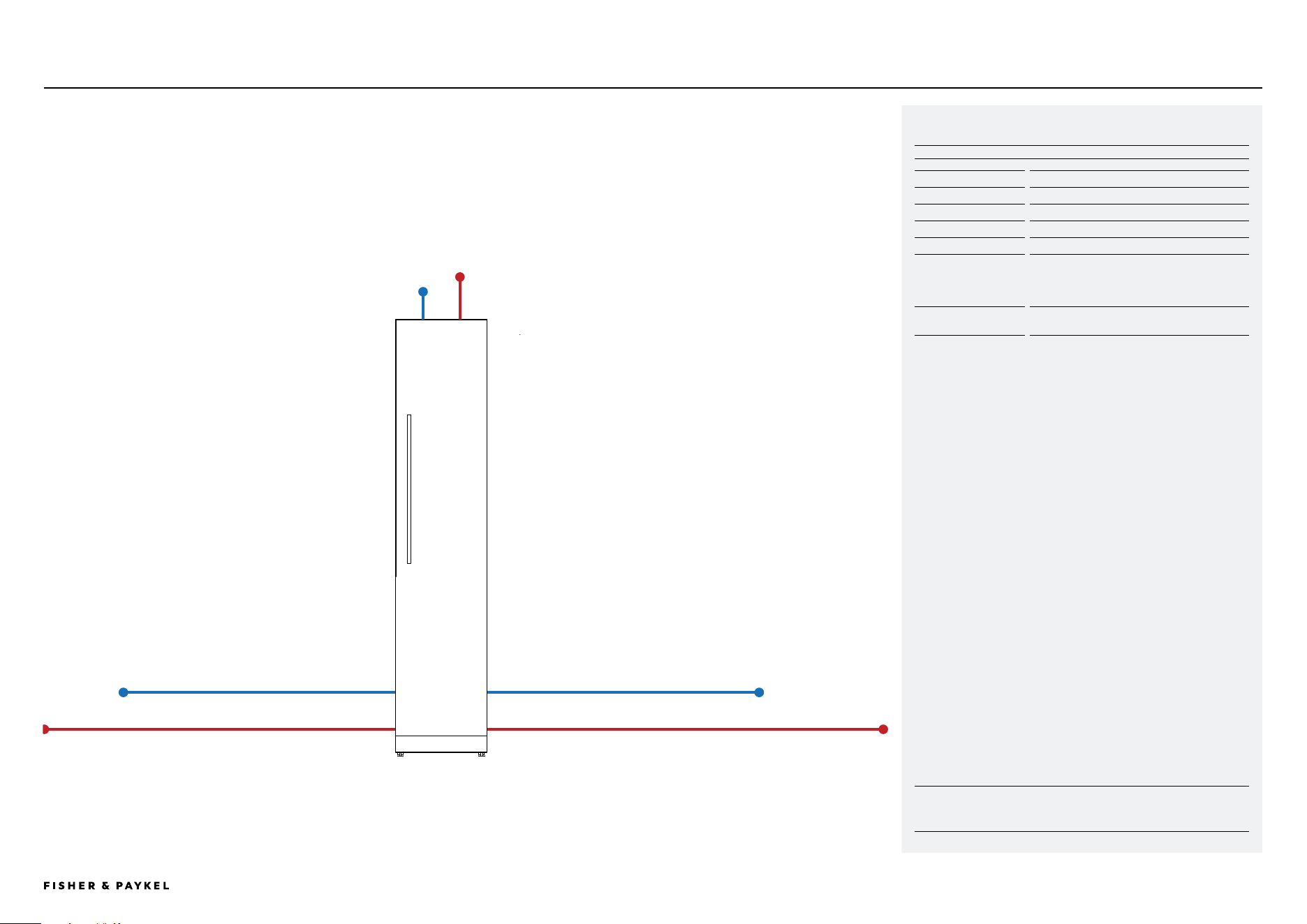
18" Freezer
SPECIFICATIONS | ELECTRICAL AND PLUMBING RS1884FLJE1, RS1884FLJK1
RIGHT HAND SIDELEFT HAND SIDE
Water inlet hose - 51 ¾" (1314mm)
Power cord (excluding plug) - 82 ½" (2096mm)
Water inlet hose - 39 ¾" (1010mm)
Power cord (excluding plug) - 83 9/16" (2122mm)
Electrical / Plumbing Specifications
Specifications
Electrical
Supply
230 V, 50 Hz
Service
10 A circuit
Plumbing
Supply
AU/NZ
1/2" (12.7mm) comp. stainless steel braided
with hose adopter
GB/EU/CN
3/4" (19mm) comp. stainless steel braided
with hose adopter
Pressure
min 150 kPa (22 psi)
max 827 kPa (120 psi) @ 20°C (68°F)
NOTE: Connections may be located in an adjacent cabinet to either side of
the fridge.
Power cord
12 ⅜" (315mm)
Water inlet hose
5 ⅛" (130mm)
<< CONTENTS
IMPORTANT NOTE: Throughout this guide, dimensions may vary by ±2mm
(1/16''). Please read the Installation Guide for detailed information on
installing the product. For full installation instructions visit fisherpaykel.com
PAGE 4490003672C PLANNING GUIDE INTEGRATED REFRIGERATION 84" - VERSION 3 - SEPTEMBER 2024© FISHER & PAYKEL LIMITED 2024
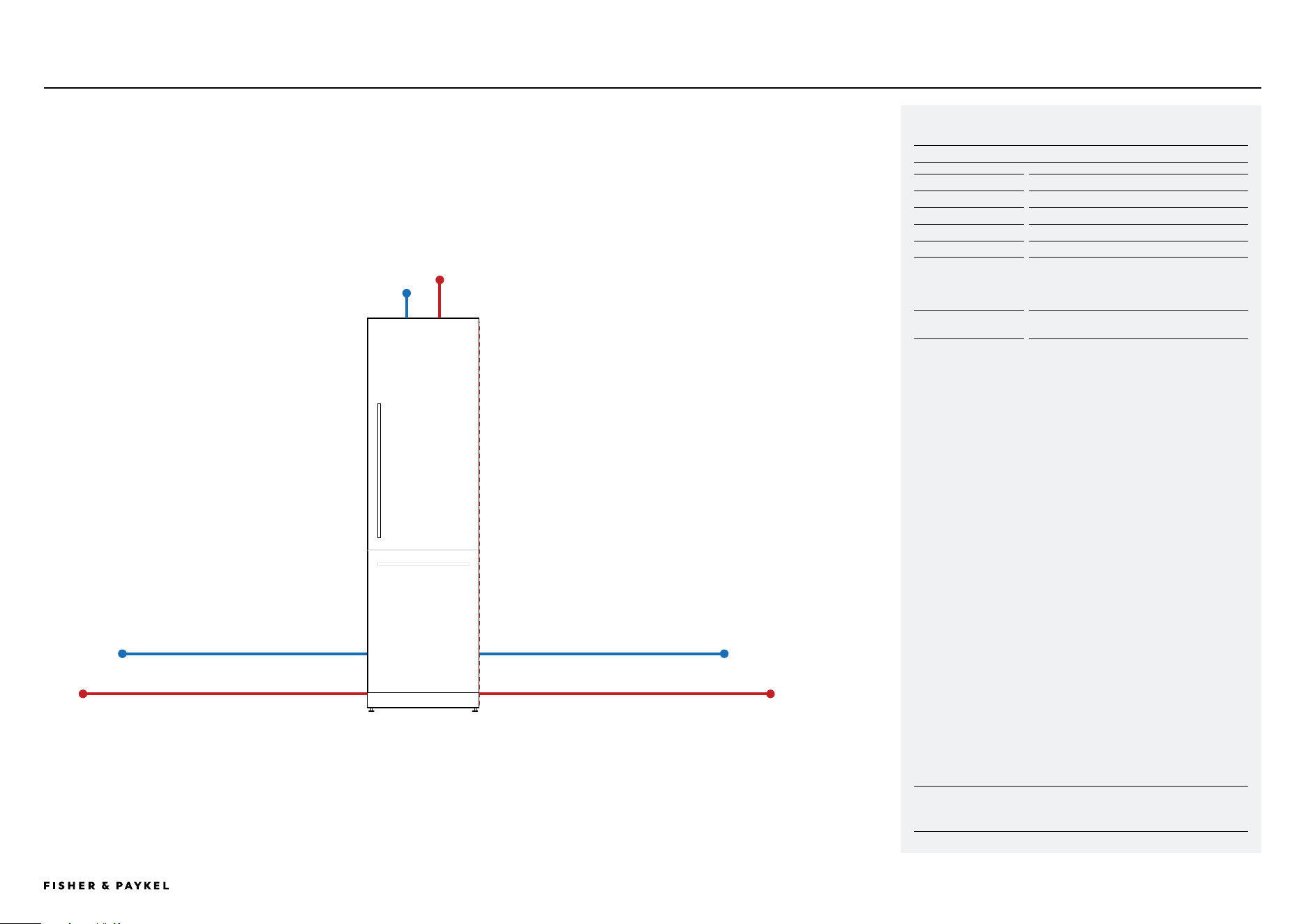
24" Models
SPECIFICATIONS | ELECTRICAL AND PLUMBING 24" MODELS
Power cord
12 ⅜" (315mm)
Water inlet hose
5 ⅛" (130mm)
RIGHT HAND SIDELEFT HAND SIDE
Water inlet hose - 87 7/16" (2196mm)
Power cord (excluding plug) - 93 ⅞" (2384mm)
Water inlet hose - 73 15/16" (1878mm)
Power cord (excluding plug) - 94 15/16" (2412mm)
Electrical / Plumbing Specifications
Specifications
Electrical
Supply
230 V, 50 Hz
Service
10 A circuit
Plumbing
Supply
AU/NZ
1/2" (12.7mm) comp. stainless steel braided
with hose adopter
GB/EU/CN
3/4" (19mm) comp. stainless steel braided
with hose adopter
Pressure
min 150 kPa (22 psi)
max 827 kPa (120 psi) @ 20°C (68°F)
NOTE: Connections may be located in an adjacent cabinet to either side of
the fridge.
<< CONTENTS
IMPORTANT NOTE: Throughout this guide, dimensions may vary by ±2mm
(1/16''). Please read the Installation Guide for detailed information on
installing the product. For full installation instructions visit fisherpaykel.com
PAGE 4590003672C PLANNING GUIDE INTEGRATED REFRIGERATION 84" - VERSION 3 - SEPTEMBER 2024© FISHER & PAYKEL LIMITED 2024
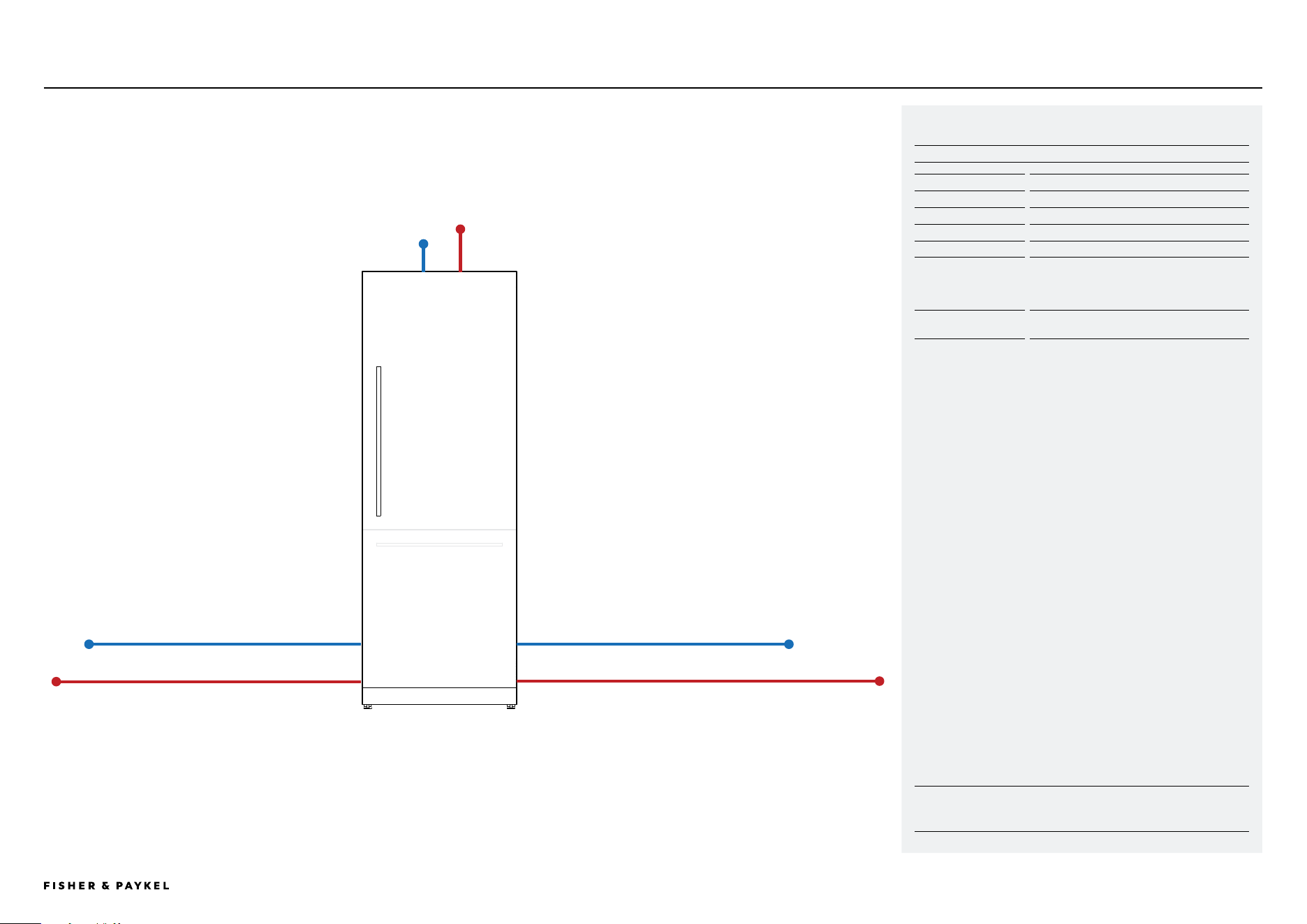
30" Models
SPECIFICATIONS | ELECTRICAL AND PLUMBING 30" MODELS
Power cord
12 ⅜" (315mm)
Water inlet hose
5 ⅛" (130mm)
RIGHT HAND SIDE
LEFT HAND SIDE
Water inlet hose* - 69 ¼" (1759 mm)
Power cord (excluding plug) - 76 ½" (1943 mm)
Water inlet hose* - 68 7/32" (1733 mm)
Power cord (excluding plug) - 77 9/16" (1970 mm)
Electrical / Plumbing Specifications
Specifications
Electrical
Supply
230 V, 50 Hz
Service
10 A circuit
Plumbing
Supply
AU/NZ
1/2" (12.7mm) comp. stainless steel braided
with hose adopter
GB/EU/CN
3/4" (19mm) comp. stainless steel braided
with hose adopter
Pressure
min 150 kPa (22 psi)
max 827 kPa (120 psi) @ 20°C (68°F)
NOTE: Connections may be located in an adjacent cabinet to either side of
the fridge.
<< CONTENTS
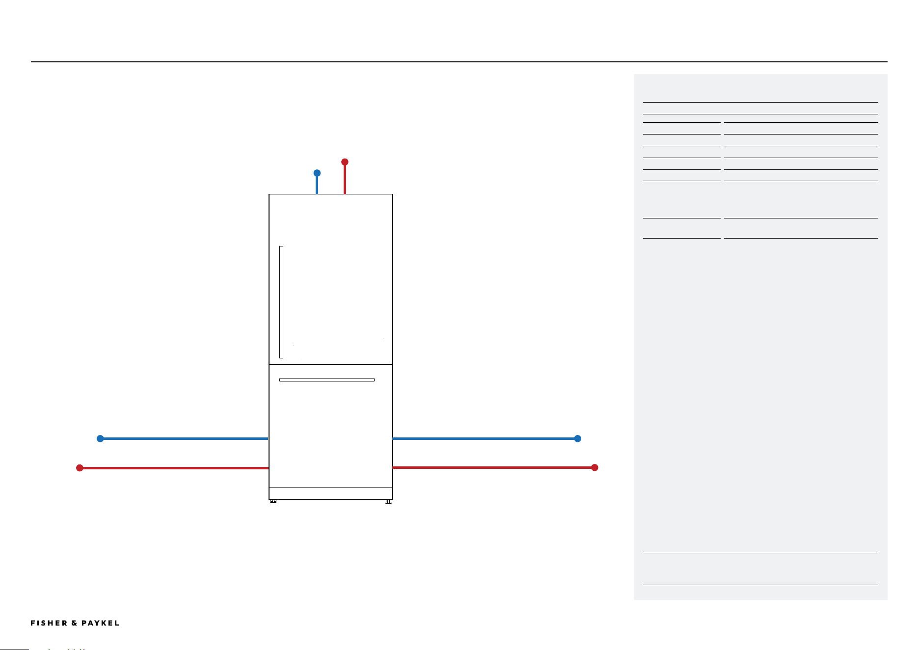
IMPORTANT NOTE: Throughout this guide, dimensions may vary by ±2mm
(1/16''). Please read the Installation Guide for detailed information on
installing the product. For full installation instructions visit fisherpaykel.com
PAGE 4690003672C PLANNING GUIDE INTEGRATED REFRIGERATION 84" - VERSION 3 - SEPTEMBER 2024© FISHER & PAYKEL LIMITED 2024
36" Refrigerator Freezer
SPECIFICATIONS | ELECTRICAL AND PLUMBING 36" MODELS
Power cord
12 ⅜" (315mm)
Water inlet hose
5 ⅛" (130mm)
RIGHT HAND SIDE
LEFT HAND SIDE
Electrical / Plumbing Specifications
Specifications
Electrical
Supply
230 V, 50 Hz
Service
10 A circuit
Plumbing
Supply
AU/NZ
1/2" (12.7mm) comp. stainless steel braided
with hose adopter
GB/EU/CN
3/4" (19mm) comp. stainless steel braided
with hose adopter
Pressure
min 150 kPa (22 psi)
max 827 kPa (120 psi) @ 20°C (68°F)
NOTE: Connections may be located in an adjacent cabinet to either side of
the fridge.
Water inlet hose* - 82 11/16" (2100 mm)
Power cord (excluding plug) - 69 9/16" (1665mm)
Water inlet hose* - 48 ⅓2" (1220 mm)
Power cord (excluding plug) - 71 1/16" (1805 mm)
<< CONTENTS

© FISHER & PAYKEL LIMITED 2024 PAGE 4790003672C PLANNING GUIDE INTEGRATED REFRIGERATION 84" - VERSION 3 - SEPTEMBER 2024