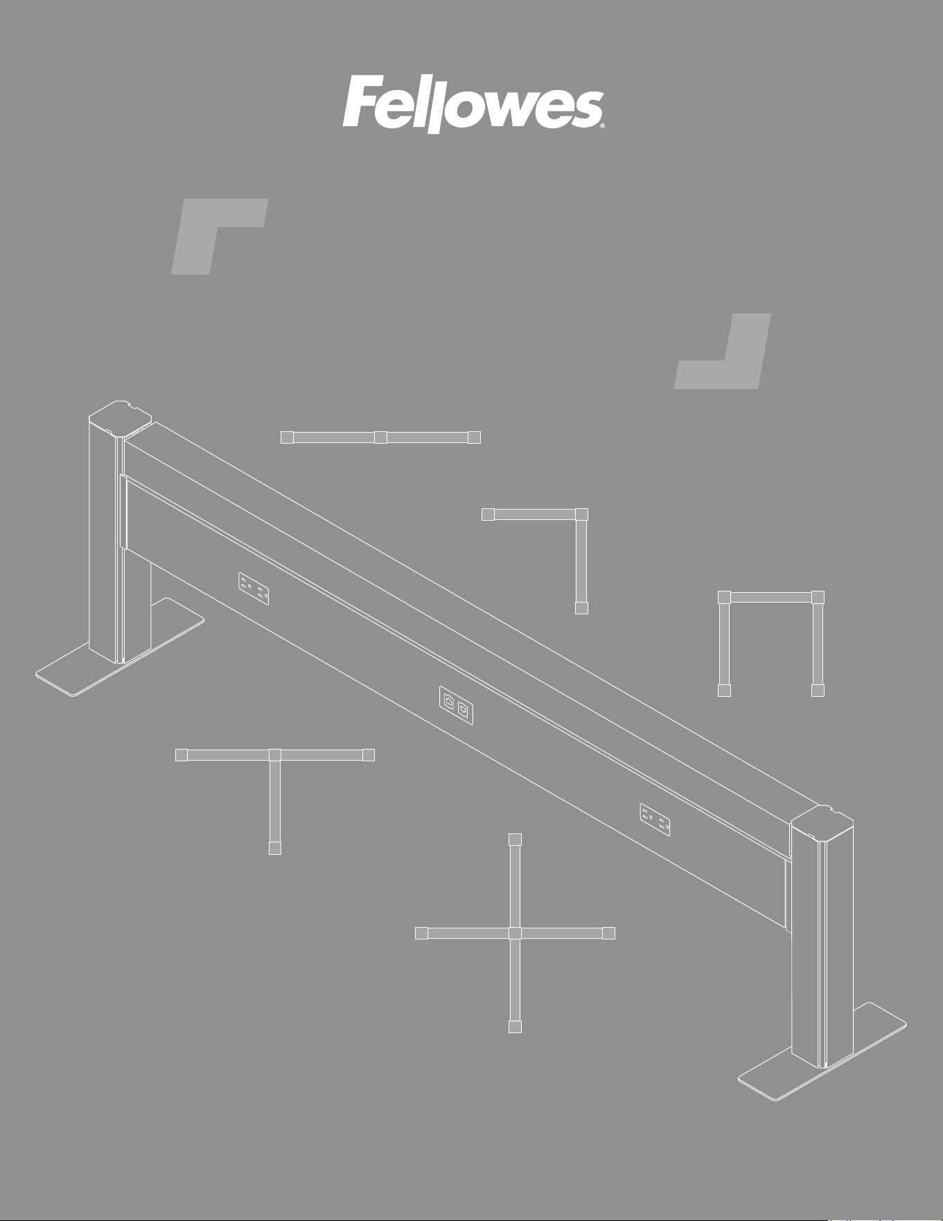
Railway
™
data and power solution
INSTALLATION INSTRUCTIONS
linear
3-way
4-way
90
˚
bullpen
Page 2
• Read and follow all instructions and warnings before use. Save these instructions for future reference.
• Use this product only in the manner intended by the manufacturer. If you have questions, please contact
the manufacturer.
• Only a licensed electrician should connect the power feed to building power.
• This product is for indoor use only.
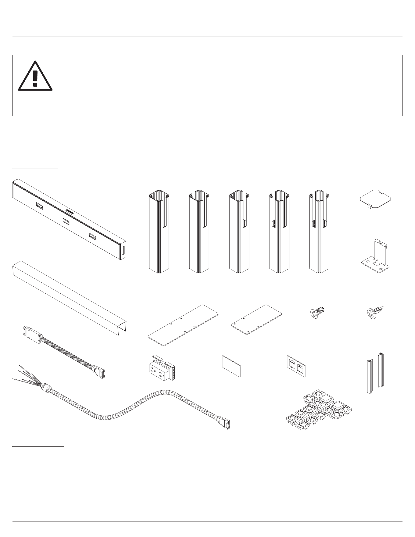
Railway™ Components and tools
Please review these instructions before beginning the installation. Use the illustrations below and the table on the next
page to check that the all components needed for your installation were provided with your order. Do not discard the
packaging until the product works to your satisfaction.
Components
rail assembly
36", 48", 60", or 72"
top data cover
36", 48", 60", or 72"
voice/data plate
voice/data
adapter kit
cover plate
jumper cable
22"
power feed
receptacle
rail posts
post feet
post cap
rail connectors
foot screws
mounting bracket
mounting bracket
screws
end post
(1 cutout)
180° post
(2 cutouts)
full
foot
#12-24x½"
Phillips #3 flat head
#8x½" self-tapping
Phillips #2 flange head
half
foot
90° post
(2 cutouts)
3-way post
(3 cutouts)
4-way post
(4 cutouts)
Tools required
• Phillips screwdriver
• Power drill with Phillips #2 and #3 bits
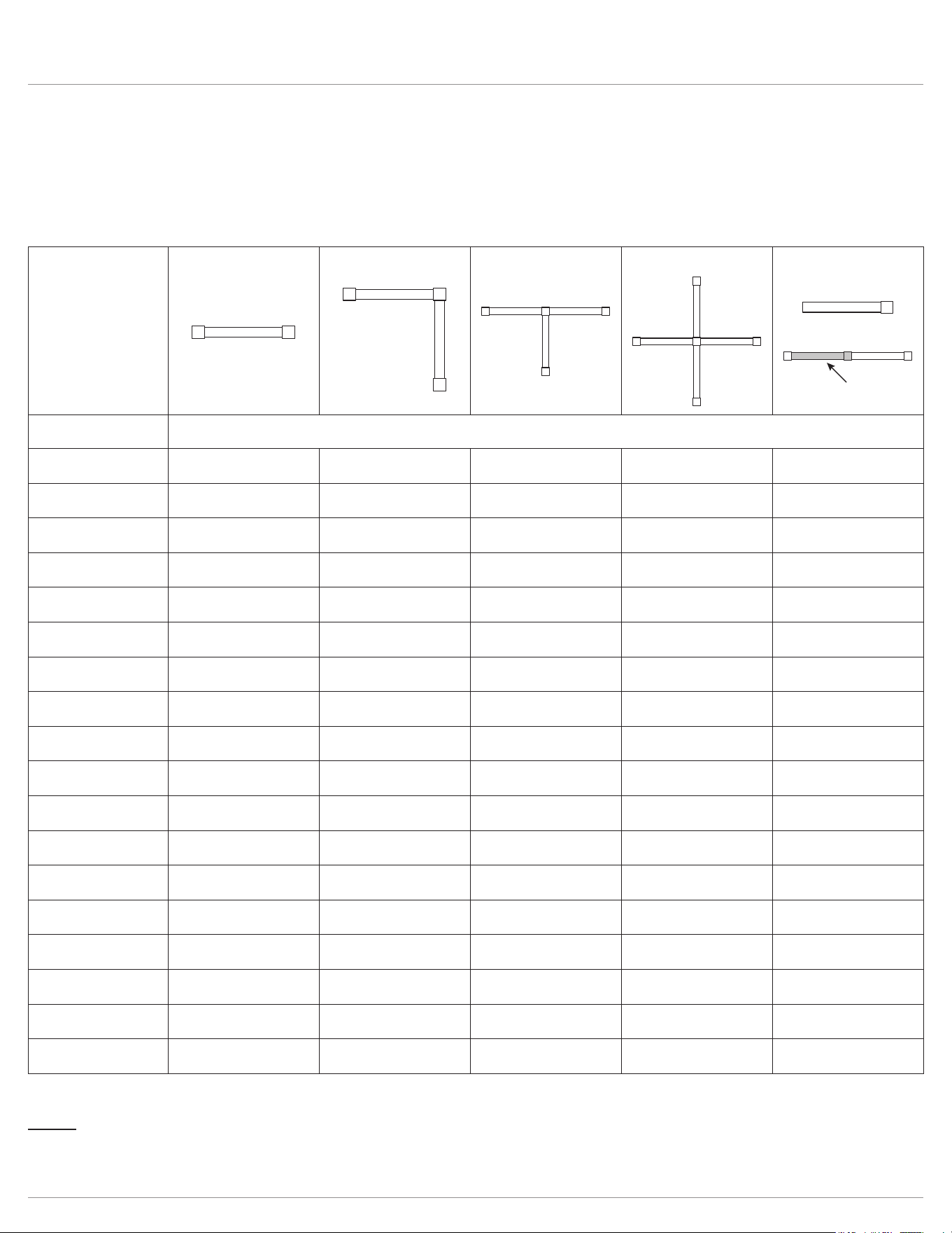
Railway™ Component quantities by conguration
Page 3
The table below can be used to verify the quantities of each component provided with your order. The minimum number
of rails is shown for each conguration. Additional rails may be added to any of the congurations. Use the “additional
rail(s)” column to calculate the number of added components per additional rail. Bullpen congurations are congured as a
90-degree plus an additional rail with a 90-degree post instead of a 180-degree. Be sure to read the notes under the table
for further details related to the congurations.
Notes
• Power outlets and voice/data ports can be on one side of the rail (single run) or both sides (double run).
• Cover plates are installed when electrical receptacles or voice/data plates are not used.
conguration
linear 90° 3-way 4-way additional rail
(
s
)
item quantity
rail 1 2 3 4 1 per added rail
rail cover 1 2 3 4 1 per added rail
end post 2 2 3 4 —
180° post — — — —
1 per added rail
(rail added in-line)
90° post — 1 — — —
3-way post — — 1 — —
4-way post — — — 1 —
full or half foot
*
2 3 4 5 1 per added rail
foot screws 8 12 16 20 4 per added rail
mounting bracket 2 4 6 8 2 per added rail
mounting bracket
screws
6 12 18 24 6 per added rail
rail connectors 4 8 12 16 4 per added rail
post cap 2 3 4 5 1 per added rail
receptacle
2 (single run)
4 (double run)
4 (single run)
8 (double run)
6 (single run)
12 (double run)
8 (single run)
16 (double run)
2 or 4 per added rail
(match adjacent rail)
voice/data plate
1 (single run)
2 (double run)
2 (single run)
4 (double run)
3 (single run)
6 (double run)
4 (single run)
8 (double run)
1 or 2 per added rail
(match adjacent rail)
voice/data adapter
kit
1 2 3 4 1 per added rail
jumper cable — 1 2 3 1 per added rail
power feed 1 1 1 1 —
linear example:
added rail
*
The half foot is used when the unit will be positioned against a wall. Otherwise, the full foot is used.
Railway™ Assembly
Page 4
mounting
bracket
position
rail width
apart
The following procedures are for a single rail two-post unit. These basic procedures apply to any Railway conguration.
Contact Customer Service if you have any questions: 800.833.3746
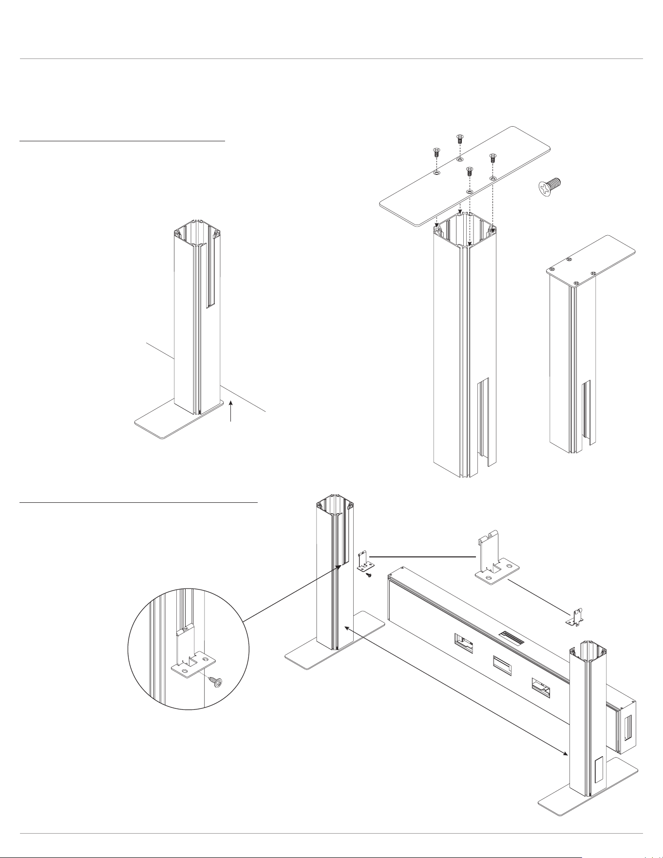
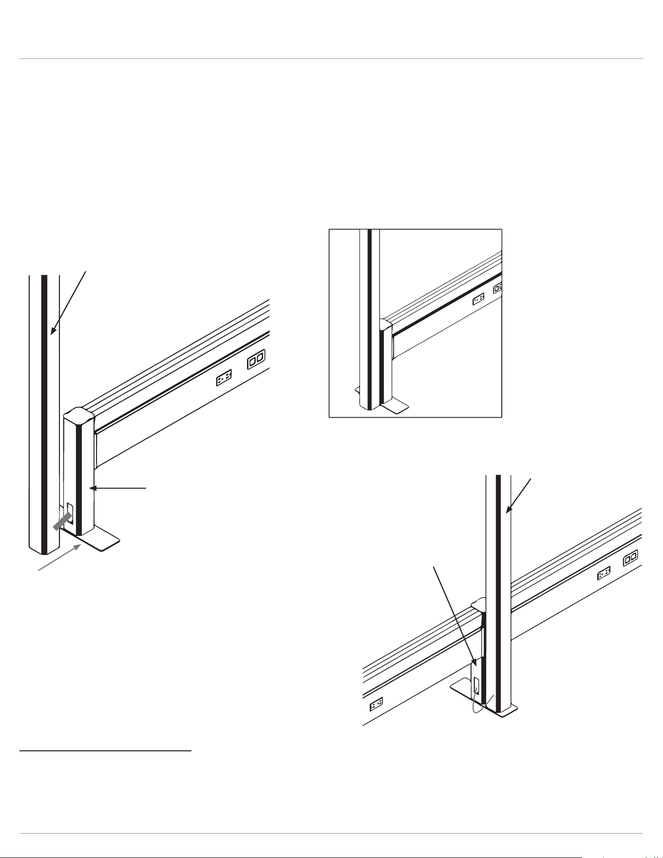
Step #1: attach feet to base of posts
• Make sure to use a #3 Phillips bit for the #12-24x ½” screws.
• Use four Phillips at head screws per foot.
• Install the full foot or half foot perpendicular to the direction of the rail.
• Use the half foot when the posts will be positioned 4" or less from the
wall or baseboard.
#12-24x½" (#3 Phillips bit)
full foot
half foot
half foot
4" or less
wall
Step #2: hook mounting brackets to posts
• Stand the post assemblies upright, with the cutouts facing
each other.
• Position the posts rail width apart.
• Hook the mounting brackets to the bottom of the cutouts.
fasten mounting brackets
to post and rail
secure rail with
rail connectors
place rail on
mounting brackets
#8x½"
top of
connector
3
2
1
Railway™ Assembly
Page 5
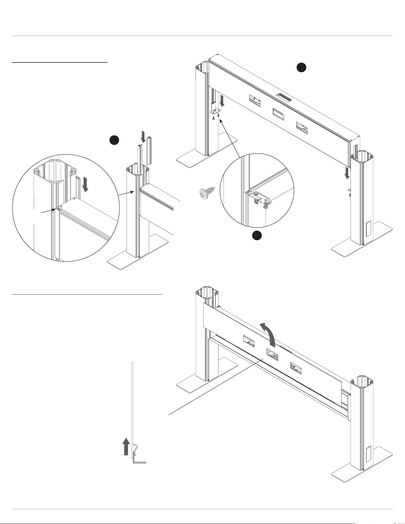
Step #3: attach rail to posts
• Place the rail onto the mounting brackets.
• Secure the rails to the post using the rail connectors, as
shown below.
• Fasten each mounting bracket to the post and rail using
three #8 self-tapping Phillips ange head screws.
— Screw the bracket to the post with a screw through the
hole in the tab.
— Screw the bracket to the rail with two screws through
the bottom ange.
rail assembly
side cover
rail
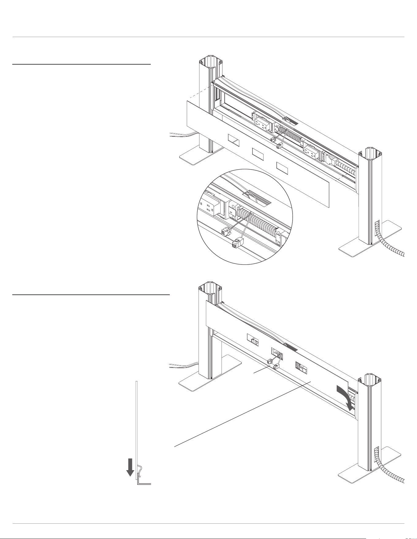
Step #4: remove rail assembly side cover(s)
• Lift the side cover from the rail and pull it out.
• If this is a double-run Railway (power outlets on both
sides of rail), remove the side cover from both sides.
power block
insert
receptacles
secure receptacles into
power block connectors
plastic
cover
connect
securely
power feed
Railway™ Assembly
Page 6
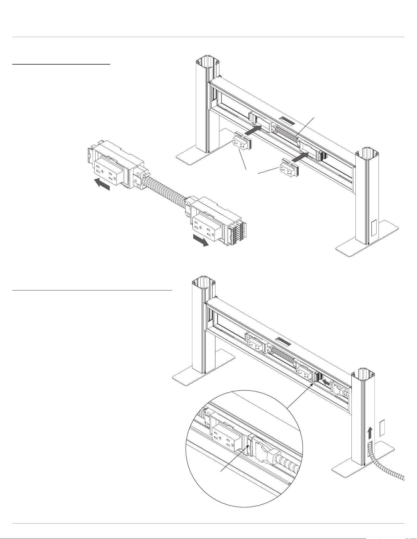
Step #5: install receptacles
• Insert the electrical receptacles into the power block.
• Then secure each receptacle into the power block
connectors by pushing the receptacles away from the
middle of the rail assembly toward the posts.
IMPORTANT: Check that the receptacles are securely
connected to the power block by sliding them back
and forth.
Step #6: connect power feed to power block
• Remove the plastic cover from the base of the end post.
• Route the power feed up through the post and into the
rail assembly.
• Insert the connector on the power feed into the power
block.
• Coil the remaining power feed for safety.
IMPORTANT: Check that the power feed is securely
connected to the power block.
NOTE: The power feed may be connected to
the building’s power through the oor, wall,
or ceiling.
Railway™ Assembly
Page 7
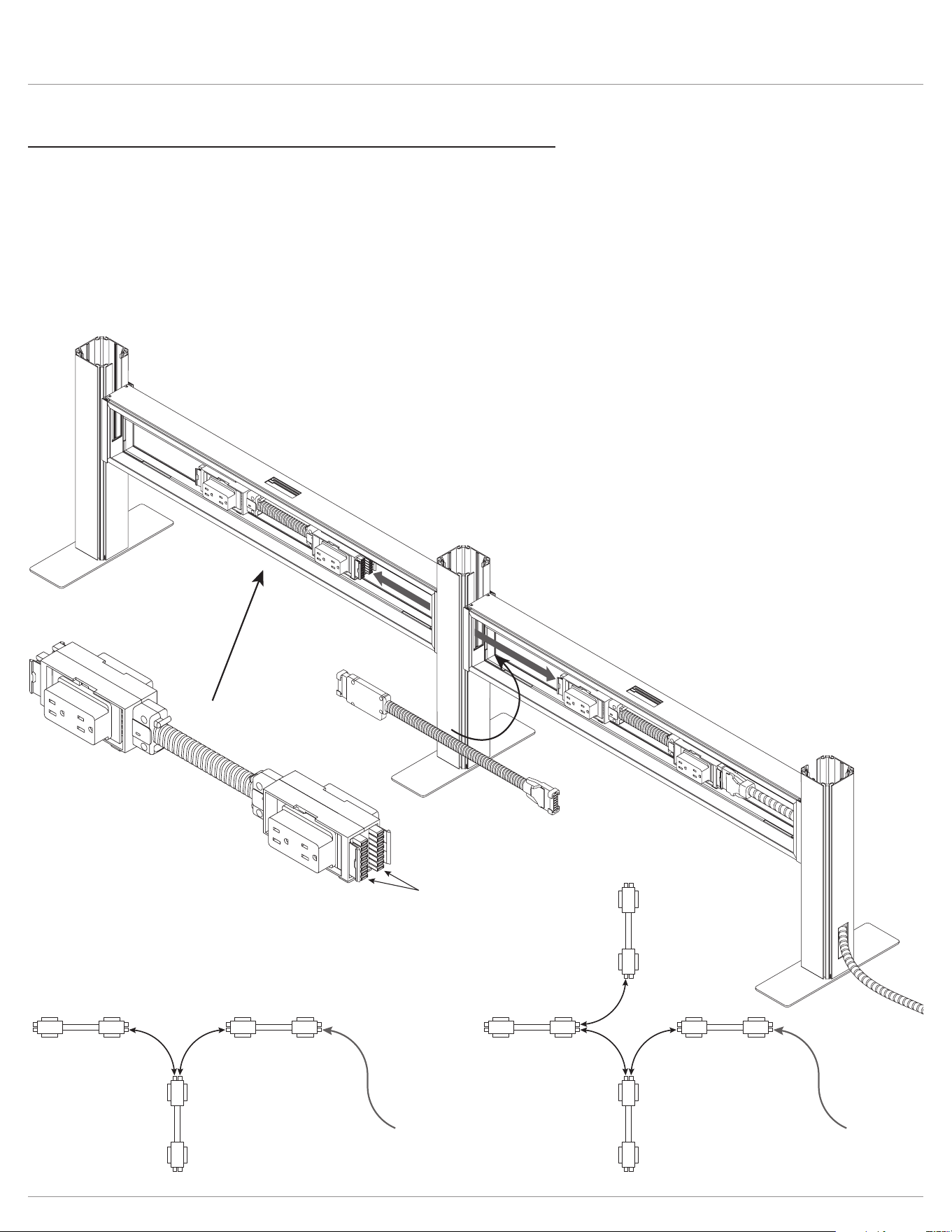
Step #7: connect power blocks with jumper cable(s) if necessary
One or more jumper cables are used to connect power blocks in two or more rail assemblies. Skip this step if your unit
has only one rail assembly.
• Run the jumper cable through the openings in the rail ends and post.
• Insert the connectors on the jumper cable onto the power block in each rail assembly.
• With 3-way congurations, two jumper cables are used. With 4-way congurations, three jumper cables are used.
— Each end of the power block can accommodate two jumper cable connections.
— Refer to the illustrations at the bottom of the page to see how the jumper cables are routed for 3-way and 4-way congurations.
IMPORTANT: Check that each end of the jumper cable is securely connected to the power block.
accommodates two
jumper cable connections
power block
power feed
jumper
cables
jumper
cables
3-way routing 4-way routing
power feed
jumper
cable
voice/data
wires
rail assembly
side cover
jacks
rail
Railway™ Assembly
Page 8
Step #8: route voice and/or data wires
Skip this step if voice/data wires will not be used with
the unit.
• If routing through the base of an end post, remove the
plastic cover at the base of the post.
• Route the wires up through the post and out the
slotted opening above the rail.
• Route the wires across the top of the rail
assembly and down through the center opening.
• The wires may be routed in other appropriate
ways depending on installation type and installer
preference, as long as the voice/data jacks exit
the center of the rail assembly, as shown.
Step #9: reinstall rail assembly side cover(s)
• Reverse the procedure described in Step #4.
• Pull the jacks out through the center hole in the side cover
before securing the cover in place.
Railway™ Assembly
Page 9
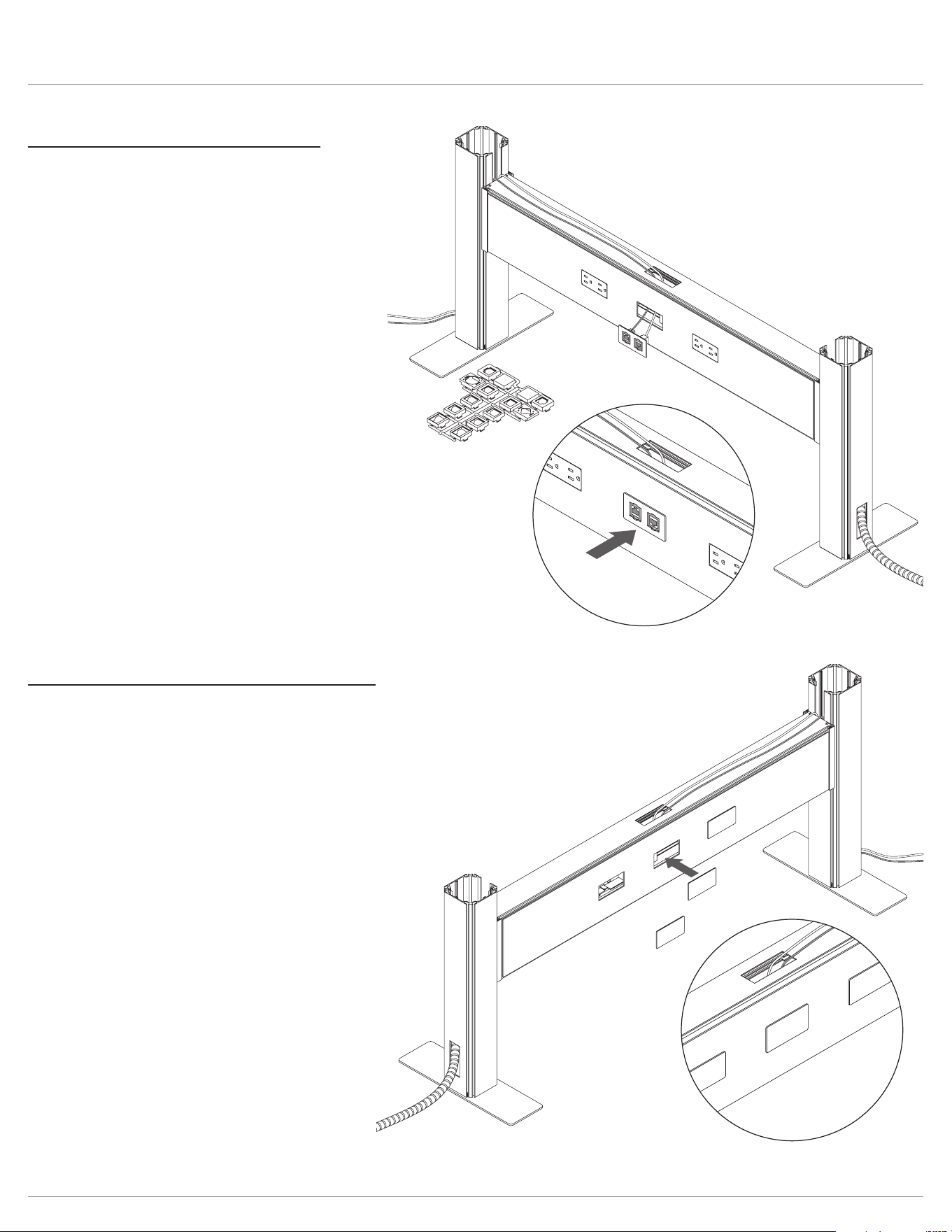
Step #10: install voice/data plate(s)
Skip this step if voice/data wires will not be used with
the unit; instead, install a cover plate over the opening
(see Step #11).
• Using the appropriate adapters in the voice/data adapter
kit, attach the jacks to the voice/data plate.
• Insert the voice/data plate into the center opening of the
side cover and push it securely in place.
push plates into
side cover
Step #11: install cover plate(s) if necessary
• Install cover plates into any unused openings in the side covers.
— In the example shown, the Railway is “single run,” with power on only one side of the rail assembly.
— The three openings on the other side of the rail assembly should be covered.
• Push the cover plates into the side cover until they snap into place.
voice/data
plate
voice/data
adapter kit
push plate into
side cover
Railway™ Assembly
Page 10
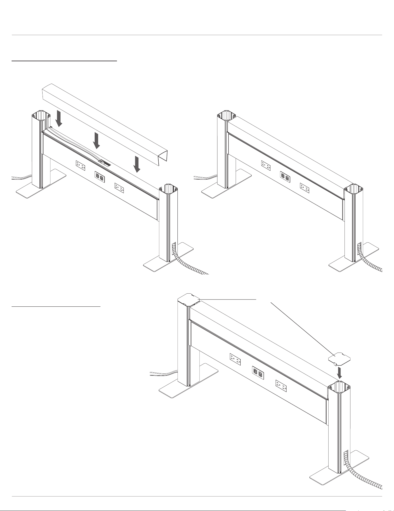
Step #13: install post caps
• Place post caps on the top of each end post as shown.
post caps
Step #12: install top data cover
• Snap the top data cover onto the top of the rail assembly to conceal any wiring on the top of the rail and to provide a nished
appearance.
Railway™ Power connection
Page 11
Step #14: connect power feed to building power
(licensed electrician required)
• The connection to building power may be made through the oor,
wall, or ceiling.
• A tag attached to the power feed shows the required wiring.
• Check that there is power to all receptacles. The licensed electrician
should correct any problems.
• A 144.0" ceiling feed is used when power must be hardwired and "dropped" in from the ceiling. Specify power pole separately (also
compatible with California Title 24).
• Fellowes oers special feeds that comply with municipal standards for building and power for NY Box (-NY). Please check if any of
these special power feeds are needed on the project.
• Chicago Code Railways do not include receptacles, base/ceiling feed or jumpers.
• Please contact your local electrician for sourcing these items. When ordering for Chicago Code applications, receptacles should
measure 1.125" in depth minimum so block protrudes beyond the face of the rail.
• The power pole sits next to the Railway system; this does not attach or tie into the Railway system itself.
• The power pole is 3.0" X 3.75" x 142" long.
• It attaches to the post on its 3.0" side, which means it will lengthen the Railway by 3.75."
• Only available in black plastic.
Field Cut Opening for In-Feed to exit Power Pole to enter Railway
System at post with knockout.
Slide Power Pole so it sits up against the End Post
End Post includes knockout for
In-Feeds (POSTKIT-180KO-DBL)
Power Pole (RAIL-POLE-142) & Ceiling
In-Feed (CEILINGFEED-144)
180° Inline Post with
knockout for In-Feeds
(POSTKIT-180KO-DBL)
Field Cut Opening for In-Feed to exit Power Pole to enter Railway
System at post with knockout.
Power Pole (RAIL-POLE-142)
& Ceiling In-Feed
(CEILINGFEED-144)

© 2023 Fellowes, Inc. | Part #412832 Rev B
To contact a Fellowes
®
service representative, call 1-800-833-3746
Warranty information can be found by contacting customer service, your sales representative or by visiting www.fellowes.com


