AUTOMATIC TYRE CHANGER
MODEL NO: TC10
Thank you for purchasing a Sealey product. Manufactured to a high standard, this product will, if used according to these
instructions, and properly maintained, give you years of trouble free performance.
IMPORTANT: PLEASE READ THESE INSTRUCTIONS CAREFULLY. NOTE THE SAFE OPERATIONAL REQUIREMENTS, WARNINGS & CAUTIONS. USE
THE PRODUCT CORRECTLY AND WITH CARE FOR THE PURPOSE FOR WHICH IT IS INTENDED. FAILURE TO DO SO MAY CAUSE DAMAGE AND/OR
PERSONAL INJURY AND WILL INVALIDATE THE WARRANTY. KEEP THESE INSTRUCTIONS SAFE FOR FUTURE USE.
TC10 Issue 4 (3,4) 28/08/24
Original Language Version
© Jack Sealey Limited
Refer to
instructions
Electrical
shock
hazard
Crushing
of hands
hazard
Wear eye
protection
Wear protective
gloves
Wear ear
protection
Wear safety
footwear
Wear protective
clothing
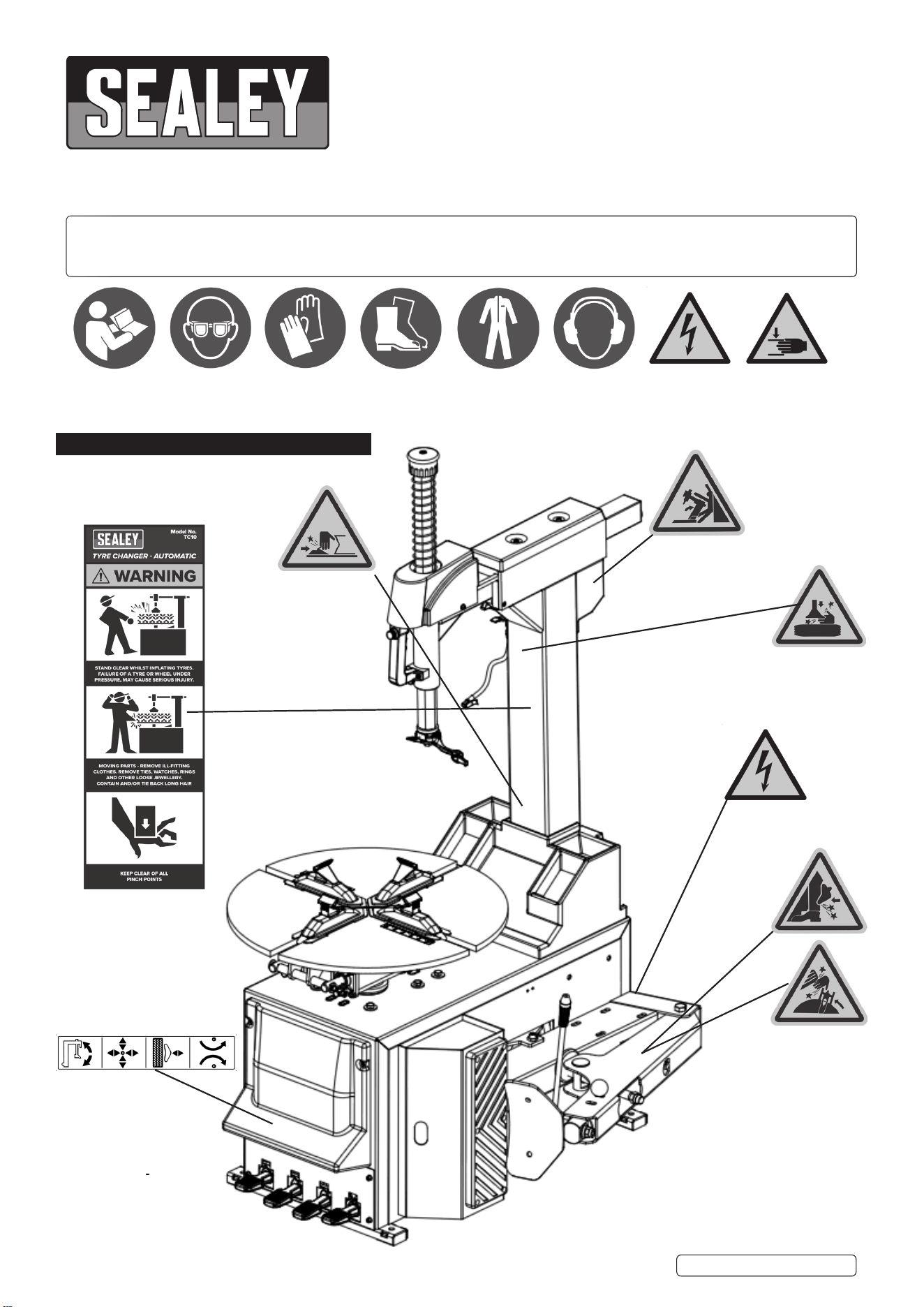
DO NOT stand
behind the
column
DO NOT put any
body part under
the tool head
When bead
breaking the
blade moves
very quickly to
the left. The
operator should
not stand
between the
blade and
the tyre
WARNING!
Electricity
When clamping
the rim, DO NOT
place hand or
any other part
of the body
between the
clamping jaw and
the wheel rim.
1. WARNING LABEL LOCATIONS

Original Language Version
© Jack Sealey Limited
2. SAFETY
2.1. ELECTRICAL SAFETY
WARNING! It is the user’s responsibility to check the following:
9 Check all electrical equipment and appliances to ensure that they are safe before using. Inspect power supply leads, plugs and
all electrical connections for wear and damage. Sealey recommend that an RCD (Residual Current Device) is used with all electrical
products.
Electrical safety information. It is important that the following information is read and understood:
9 Ensure that the insulation on all cables and on the appliance is safe before connecting it to the power supply.
9 Regularly inspect power supply cables and plugs for wear or damage and check all connections to ensure that they are secure.
Important: Ensure that the voltage rating on the appliance suits the power supply to be used and that the plug is tted with the
correct fuse.
8 DO NOT pull or carry the appliance by the power cable.
8 DO NOT pull the plug from the socket by the cable.
8 DO NOT use worn or damaged cables, plugs or connectors. Ensure that any faulty item is repaired or is replaced immediately by a
qualied electrician.
If the cable or plug is damaged during use, switch off the electricity supply and remove from use.
Ensurethatrepairsarecarriedoutbyaqualiedelectrician.
2.2. GENERAL SAFETY
WARNING! Ensure that Health & Safety, Local Authority Regulations and general workshop practice Regulations are adhered to
when using Tyre changer. Read and fully understand instructions and safety labels attached to machine.
9 Wear appropriate Personal Protective Equipment. A full range of Personal Protective Equipment is available from your Sealey stockist.
9 Wear suitable clothing to avoid snagging. DO NOT wear jewellery. Tie back long hair.
9 Maintain machine to ensure it is in an adequate condition for safe use and optimum performance.
8 DO NOT use Tyre changer if damaged.
9 This machine should only be operated by trained personnel.
9 This machine should only be used for the purpose for which it is intended and not modied in any way.
9 The tyre changer must only be operated with specied voltage and air pressure.
WARNING! The warnings, cautions and instructions in this manual cannot cover all possible conditions and situations. The Operator/
user must apply caution and common sense.
2.3. WARNINGS AND PRECAUTIONS
9 Make sure Tyre Changer is tted/used on a dry, at, level, oil/grease free, concrete surface capable of supporting the weight of the
Tyre Changer.
9 Before each use, always examine the Tyre Changer for structural cracks/defects, damage to the clamping jaws and electrical wiring,
and any other condition that may affect the safe operation of the machine.
8 DO NOT use the Tyre Changer if any defects are found.
9 Maintain a safe working environment. Keep the work area well lit. Make sure there is adequate surrounding workspace. Always keep
the work area free of obstructions, grease, oil and other debris.
8 DO NOT use the Tyre Changer in a damp or wet location.
8 DO NOT use the Tyre Changer in areas near ammable chemicals, dusts and vapours.
9 This Tyre Changer is designed for use with most passenger cars and light commercial wheels.
8 DO NOT attempt to exceed this machine’s maximum wheel diameter of 23”.
9 Always keep hands, ngers, and feet away from the moving parts of the Tyre Changer while machine is in use.
9 Always turn OFF mains power when not in use.
9 Before using the machine, make sure tools and all other equipment is removed from the immediately vicinity.
8 DO NOT use with an extension cable. Tyre Changer needs to be mounted near a suitable plug socket.
9 Always unplug the Tyre Changer from its electrical supply before performing any inspection, maintenance, or cleaning procedures.
WARNING: People with pacemakers should consult their physician(s) before using this product. Operation of electrical equipment in
close proximity to a heart pacemaker could cause interference or failure of the pacemaker.
2.4. UNPACKING
When unpacking, check to make sure all parts shown on the Packing Lists are included. If any parts are missing or broken, please call
your Sealey distributor.
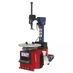
3. INTRODUCTION
Automatic tyre changer capable of changing 11” to 23” wheel rims. Suitable for most cars and light commercial vehicles. Air operated rear
tilting column and head lock. Protects alloy wheels with the added feature of plastic protectors, tted to the clamping jaws and mounting head.
Supplied with 485mm tyre lever, integrated tyre inator, tyre soap tub, air regulator and lubricator. Model No. TC10A Assist Arm is required for
use with low prole and run at tyres. See www.sealey.co.uk for demonstration video.
TC10 Issue 4 (3,4) 28/08/24
4. SPECIFICATION
Model No ......................................................................TC10
Wheel Ø Min/Max:
Internal Clamping .................................................... Ø13”-23”
External Clamping ...................................................Ø11”-20”
Wheel Depth Min/Max ...................................................3-13”
Turntable Ø .......................................................20” (508mm)
Bead breaking Force ................................................. 2500kg
Tyre Inflater ..............................................0-10bar (0-145psi)
Voltage/Phase ......................................................230V - 1ph
Motor .......................................................................... 1.1KW
Operating Pressure .............................. 8-10bar (115-145psi)
Inlet Size ..................................................................1/4”BSP
Dimensions (W x D x H) ................... 1900 ×1350 × 2050mm
Optional Accessories .................................TC10A Assist Arm
Power Supply Cable Length: .........................................2.2m
Fuse Rating .....................................................................13A
Weight .........................................................................246kg
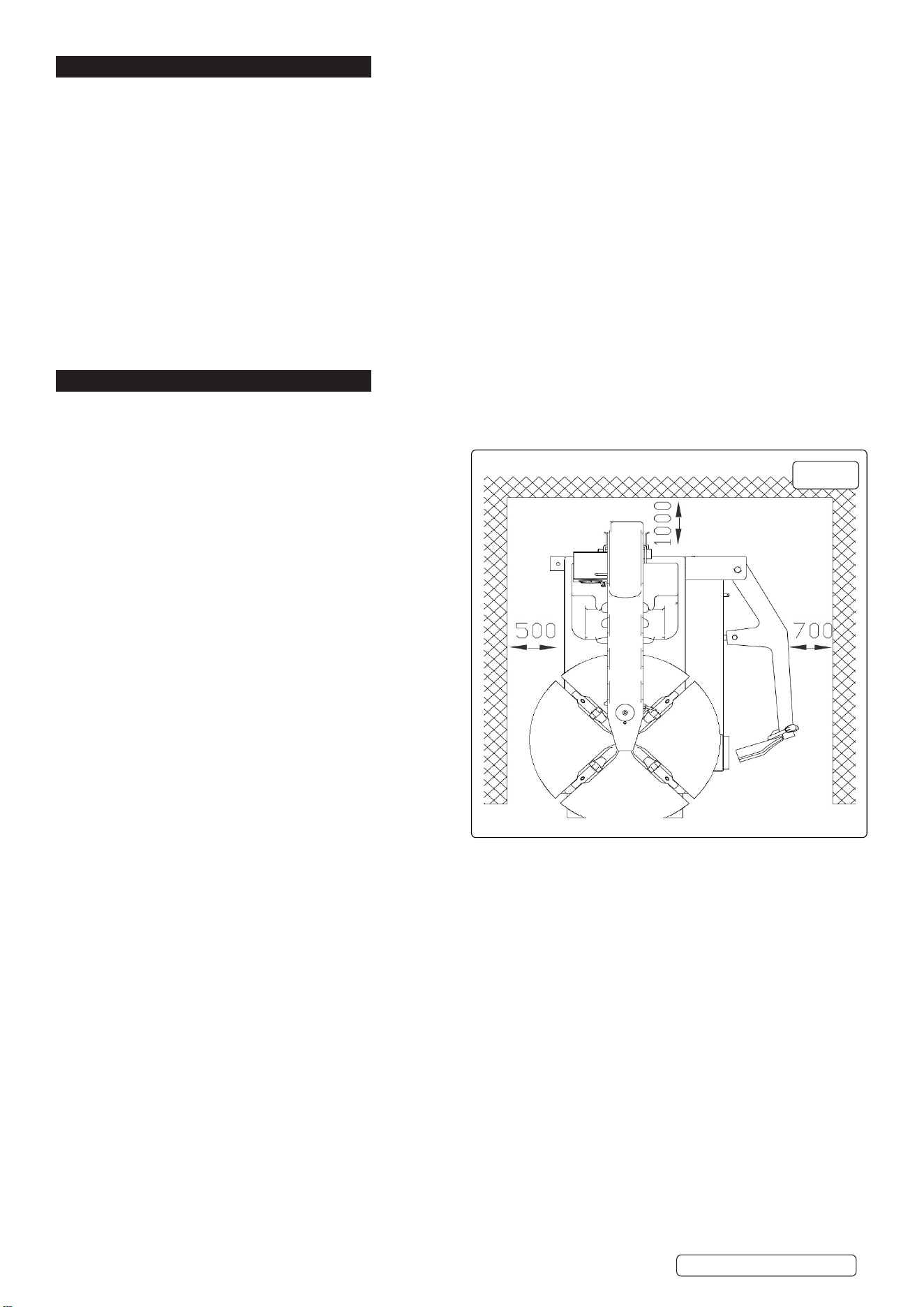
5. POSITIONING AND ASSEMBLY
5.1. Theminimumrequiredspacearoundthemachineisshowning.1.Itshouldbeboltedtoaat/levelsurfaceusing
appropriatexingsasfollows:
5.2. INSTALLATION
5.2.1. Locating The Tyre Changer:
5.2.1.1. Make sure Tyre Changer is tted/used on a dry, at, level,
oil/grease free, concrete surface capable of supporting the
weight of the Tyre Changer.
5.2.1.2. The Tyre Changer is designed for indoors use only.
8 DO NOT install or use the Tyre Changer outdoors, or in
damp or wet locations.
5.2.1.3. Make sure to check the desired location for possible
obstructions such as a low ceiling, adequate working area,
access ways, exits. The Tyre Changer should be located in
an area free of ammable materials and liquids.
5.2.1.4. Make sure the Tyre Changer is located near enough to a
plug socket so it can be plugged into directly without the
use of an extension cable.
5.2.2. Mounting The Tyre Changer To The Floor
5.2.2.1. With assistance, and with the use of a lifting device, position
in the desired location. Use the four, 13mm (1/2”) machine
mounting holes located at the base of the Body as a template
to mark the points where four oor anchor holes will be
drilled in the oor surface. Then, temporarily remove the
Tyre Changer.
5.2.2.2. Where previously marked on the concrete oor surface,
drill four 13mm (1/2”) diameter, minimum 100mm deep,
anchor holes. NOTE: Be sure to blow out the cement dust
from the drilled hole.
5.2.2.3. Move the Tyre Changer back to the desired location, and align the four machine mounting holes at the base of the Body with the four
previously drilled oor anchor holes. If necessary, level the Tyre Changer by inserting steel shims between the base of the machine
and the concrete oor surface. DO NOT exceed more than 5mm thickness of shims.
5.2.2.4. Secure the Tyre Changer to the concrete oor surface, using four 13mm (1/2”) diameter concrete anchor bolts of appropriate length,
four washers, and four nuts (not provided).
g.1
Original Language Version
© Jack Sealey Limited
TC10 Issue 4 (3,4) 28/08/24
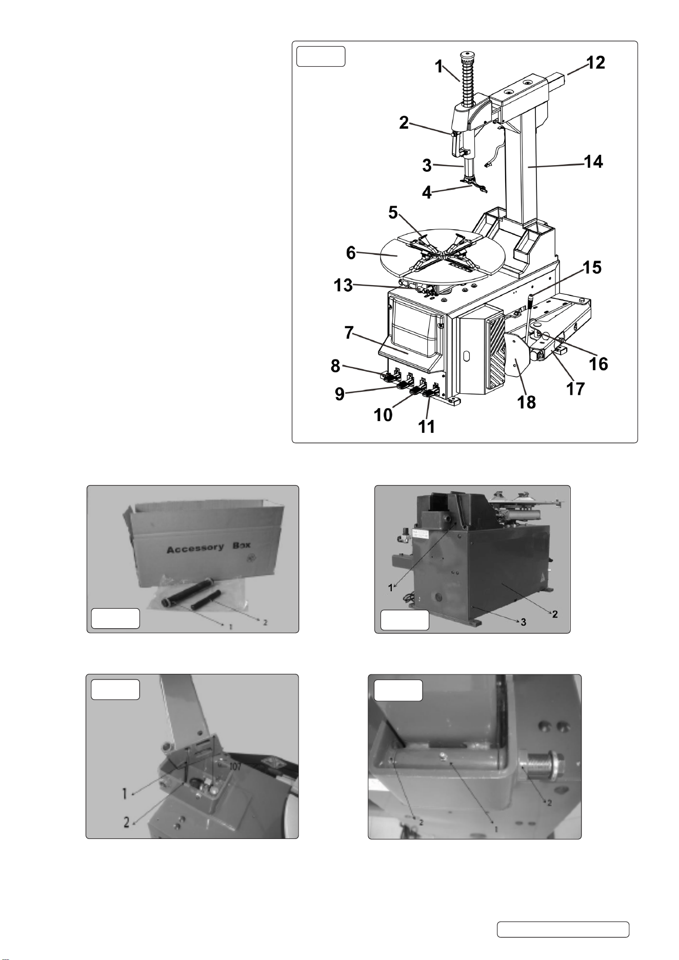
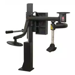
1. Vertical shaft spring
2. Handle valve
3. Hexagon shaft
4. Mounting/demounting head
5. Jaw
6. Turntable
7. Pedal label.
8. Column tilt pedal
9. Clamp pedal
10. Tyre bead braking pedal
11. Turn table pedal
12. Horizontal arm
13. Clamp turntable cylinder
14. Column
15. Blade handle
16. Bead breaking cylinder
17. Bead breaking arm
18. Bead breaking blade
5.3. COLUMN INSTALLATION
5.3.1. According to the requirements shown in g.1, position the main body of the machine. Unpack the accessory box and take out the
rotation shaft assembly g.3.1, and push out shaft assembly g.3.2. Clean the assembly and lubricate with oil.
5.3.2. Remove the xing screw g.4.1, remove the side panel g.4.2.
5.3.3. Remove the xing screw g.4.3, remove the tool box.
5.3.4. Lift up the column (two man lift) and insert the PU hose g.5.1. at the bottom into the hole g 5.2. on the top of the body. Adjust the
position of the column to make the rotation shaft bushing g.6.1 align with bearings g.6.2. Remove the nut and washer at the one
end of the rotational shaft assembly g.3.1. Push the shaft through the bushes and t the washer and tighten nut to a torque of
70Nm.
g.2
g.3
g.4
g.5
g.6
Original Language Version
© Jack Sealey Limited
TC10 Issue 4 (3,4) 28/08/24
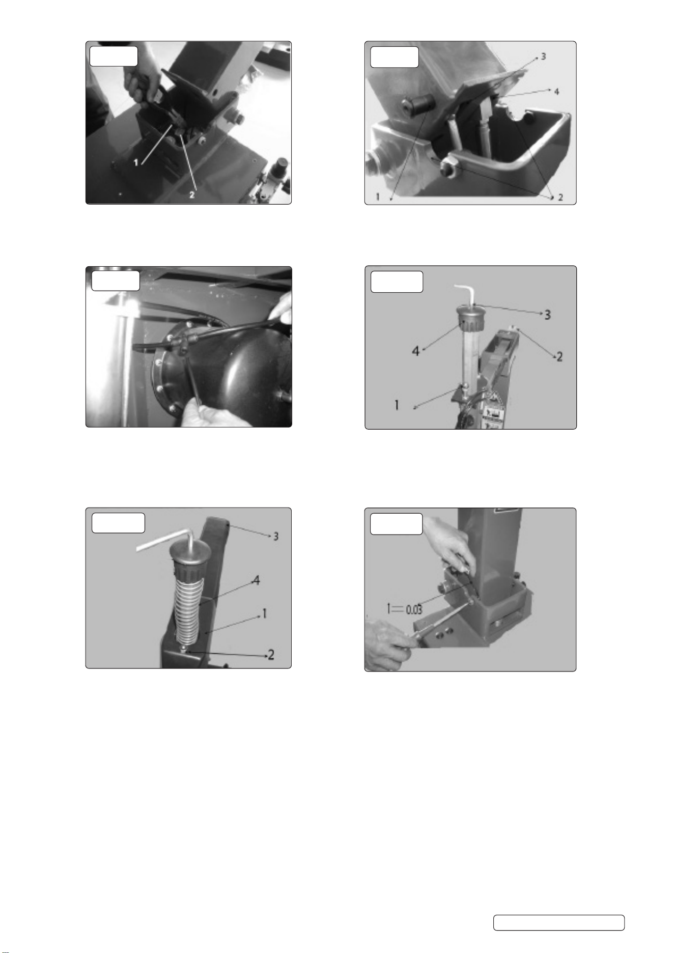
5.3.5. Tilt back the column and cut off the tie on the xed shaft g.7.1 and pull out the piston rod.
5.3.6. Position the column as shown in g.8. Remove the circlip from one end of the shaft g.3.2 and pass the shaft through the 16mm hole,
vertical retaining bar g.8.3, piston rod g.8.4 and through the hole on the opposite side of the column. Attach circlip to shaft.
5.3.7. To install the horizontal arm protective cover, remove the cap nut g.10.1, the screw at the back end g.10.2 and the screw g10.3 at
the top end of the vertical cap g.10.4. Remove cap g.10.4.
WARNING! when detaching the vertical shaft cap , support the vertical shaft to prevent the vertical shaft from falling.
5.3.8. Remove packaging from protective cover. Position as shown in g.11.
5.3.9. Twist on the cap nut g.11.2 and screw g.11.3. Install the vertical shaft spring g11.4, cap g.10.4 and screw g.10.3.
5.3.10. Adjust the column positioning screws on the two sides of the column. Release the nuts on the two sides and adjust the gap between
the head of the screw and the side of the column to 0.03mm g.12. and then lock the nut.
5.3.11. Connect the air source, use the lock air valve push button to lock the horizontal arm g.2.2. Operate the column tilt pedal g.2.8 and the
column will tilt backwards by about 25° . The speed of the movement of the column has been set to be about 2 seconds per stroke. After
a time in operation, the speed may increase or decrease, you can use the speed adjusting valve to adjust the speed. To do this
loosen the nut and turn the screw, turn the screw clockwise to decrease and counter-clockwise to increase. After adjustment, tighten the
nut.
5.3.12. Fix the side panel and tool box removed in step 5.3.2 (See g.4.2).
5.4. COMPRESSED AIR INSTALLATION
5.4.1. The compressed air regulator assembly can be found in the accessory box.
5.4.2. Use the screw provided to x the assembly on the right hand side (viewed from the back) of the body g.13.
g.7
g.9
g.11
g.8
g.10
g.12
Original Language Version
© Jack Sealey Limited
TC10 Issue 4 (3,4) 28/08/24
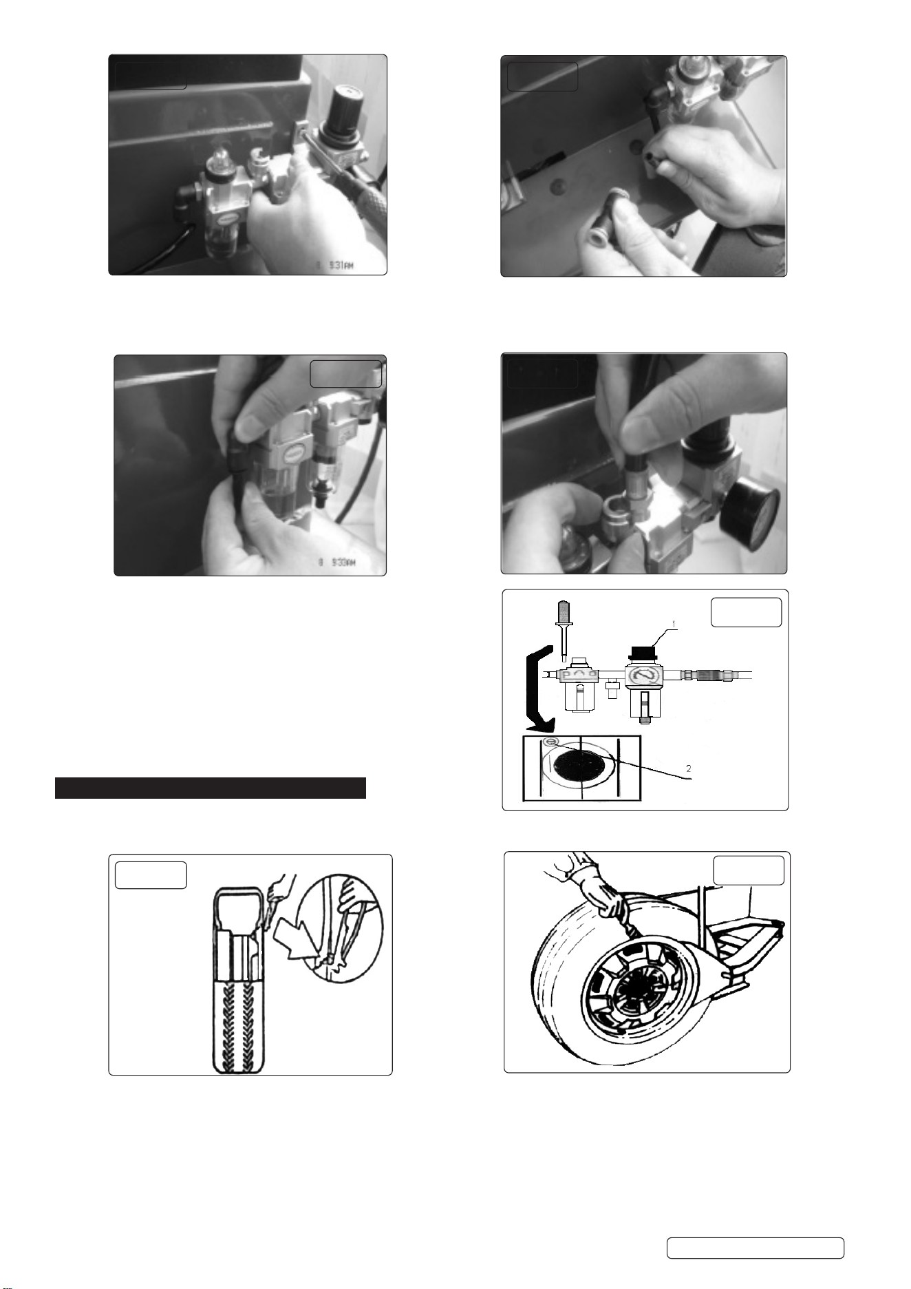
5.4.3. To connect the air hose, detach the adapter of the Ø8 PU hose on the side of the body. This adapter has the function to prevent the
hose from sliding into the body. Insert the adapter into the elbow. See the g.14 and g.15.
5.4.4. Connect the ination gun g.16. Then connect the air source.
5.4.5. The air regulator has been adjusted before leaving the factory.
If it needs adjusting, the air pressure can be adjusted by lifting
the button g.17.1 and turning clockwise to increase and anti-
clockwise to decrease. To adjust the oil feed use a screw driver
to turn screw g.17.2, clockwise to decrease ow, anti-clockwise
increase ow.
6. DEMOUNT AND MOUNT TYRE
6.1. DEMOUNT TYRE
6.1.1. Deate the air in the tyre completely and remove the valve. Use a special tool to detach any weights on the rim, g.18.
6.1.2. Place the tyre between the bead breaking blade and rubber tyre block. Position the bead breaking blade beside the lateral side of the
tyre g.19. Then operate the pedal to detach the rim from the tyre g.2.10.
g.13g.13
g.14
g.15
g.16
g.17
g.18
g.19
Original Language Version
© Jack Sealey Limited
TC10 Issue 4 (3,4) 28/08/24
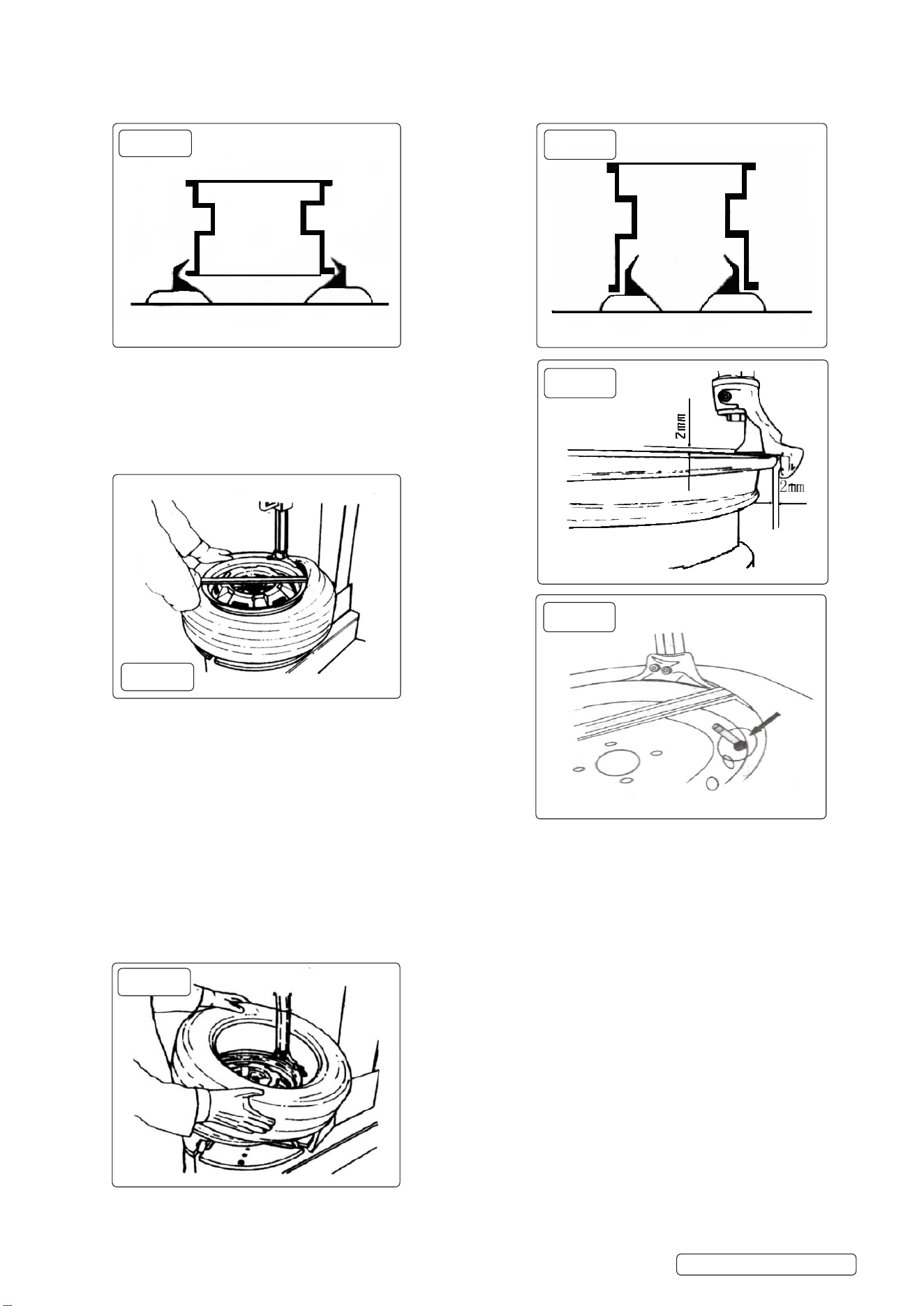
6.1.3. Repeat the operation on around the circumference of the tyre to make the tyre completely detached from the rim. Use the brush to
spread lubricant or thick soap liquid between the lip and rim. Place the wheel with the tyre detached from the rim on the turntable and
operate the clamp pedal g.2.9 to clamp the rim. Select the outer clamp g.20 or the inner clamp g.21 to clamp the wheel according
to different rim designs.
6.1.4. Move the hexagonal shaft to the working position making contact
with the rim of the wheel. Press the lock handle button g.2.2 to
lock horizontal arm. The hexagonal shaft and will automatically move
upwards and backwards a few millimetres so there is not contact
between the demounting head and the wheel rim avoiding damage.
g.22.
6.1.5. Use the tyre lever to lift the lip over the hump of the demounting
head, g.23. Operate the turntable rotation pedal g.2.11 to rotate the turntable clockwise until the rim of the wheel is fully released. If
handling a tyre with an inner tube, to avoid damaging the tube, you should keep the valve of the tyre 10cm from the right side of the
demounting head g.24.
6.1.6. If the tyre is jammed, stop the machine immediately, lift up the pedal to let the turntable rotate counterclockwise to remove the
resistance.
6.1.7. Take out the inner tube(if required) and then move up the lower lip of the tyre so it contacts with the upper edge of the rim and repeat
step 6.1.6. Detach the other lip g.25. Operate the column tilt pedal g.2.8 and the column will tilt backwards allowing removal of the
tyre.
g.20
g.23
g.25
g.21
g.24
g.22
Original Language Version
© Jack Sealey Limited
TC10 Issue 4 (3,4) 28/08/24
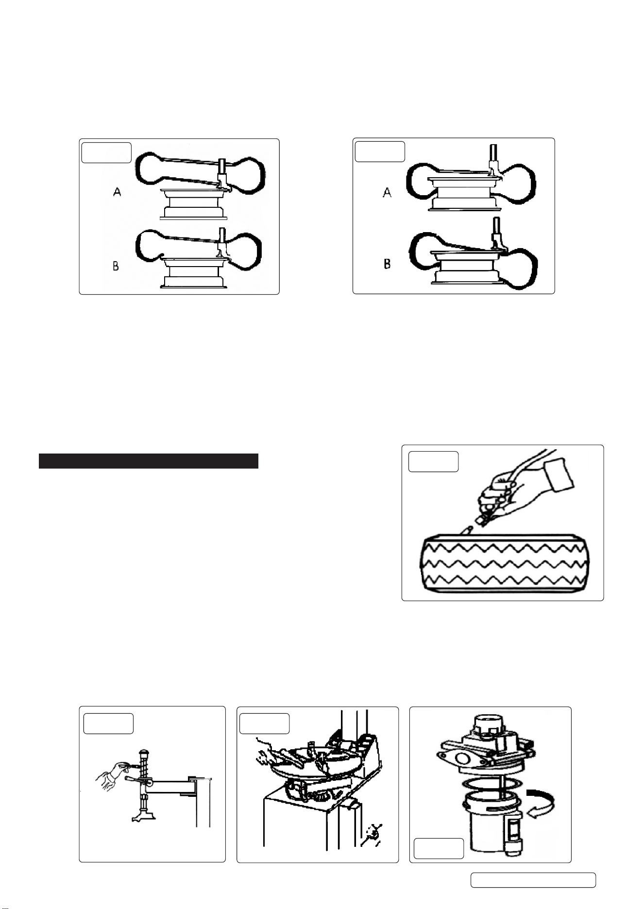
6.2. MOUNTING THE TYRE
9 Before mounting the tyre, check that the rim and tyre have the same dimension.
6.2.1. Clean up any oil or rust from the rim, select the inner or outer clamp, then lock the rim on the turntable.
6.2.2. Spread the lubrication liquid or soap liquid around the lip of the tyre. Tilt the tyre against the rim and keep the front end upwards.
Operate the column tilt pedal g.2.8 to make the column return to the down position. Move the demounting head to rmly contact the
rim g.22. Position the left of the tyre lip above the tail of the demounting tool and the right under the hump g.26.
6.2.3. Press down the right side of the tyre as hard as possible and operate the turntable pedal g.2.11 to rotate the turntable clockwise to guide
the lip into the wheel.
6.2.4. If an inner tube is required, raise up the demounting head and insert the tube into position.
6.2.5. Mount the demounting head again. Adjust the position of the upper lip. Operate the turntable rotation pedal to rotate the tyre. At this
moment, continue pressing the lip. If the tyre deforms release the pedal at once. Rotate turntable in the opposite direction if required.
Restore the tyre to its original condition and try to mount again.
6.3. STANDARD INFLATION
WARNING! Take care when inating Tyre.
6.3.1. Check the air supply to see if the air connection is OK.
6.3.2. The machine is equipped with an ination gauge for monitoring the ination of the tyre and the ination pressure.
6.3.3. Remove turntable clamps from the tyre.
6.3.4. Connect the ination hose with the tyre air valve g.28.
6.3.5. During ination, check the pressure indicated on the pressure gauge dose not exceed the scope specied by the manufacturer.
The machine is equipped with a pressure regulating vale to prevent the pressure exceeding 3.5 bar. This can be adjusted dependent on
requirements.
7. MAINTENANCE & REPAIR
9 Only trained personnel should maintain this machine. To correctly use the tyre
changer and prolong its working life, it is necessary to periodically maintain and
repair according to the instruction manual.
9 Disconnect power and air supply before any maintenance.
Release any residual air in system.
7.1. The following should be done on a monthly basis.
7.1.1. Keep the machine and working area clean.
7.1.2. Clean the hexagonal shaft and horizontal arm g.29.
7.1.3. Use machine oil to lubricate.
7.1.4. Clean the turntable jaws and its guides and use the lithium base oil to lubricate
g.30,
7.1.5. Periodically check the lubrication oil level in the oil lubricator. If the oil level is
lower than the oil scale, rell with SAE30 g.31.
7.1.6. Periodically drain the water in the water separator.
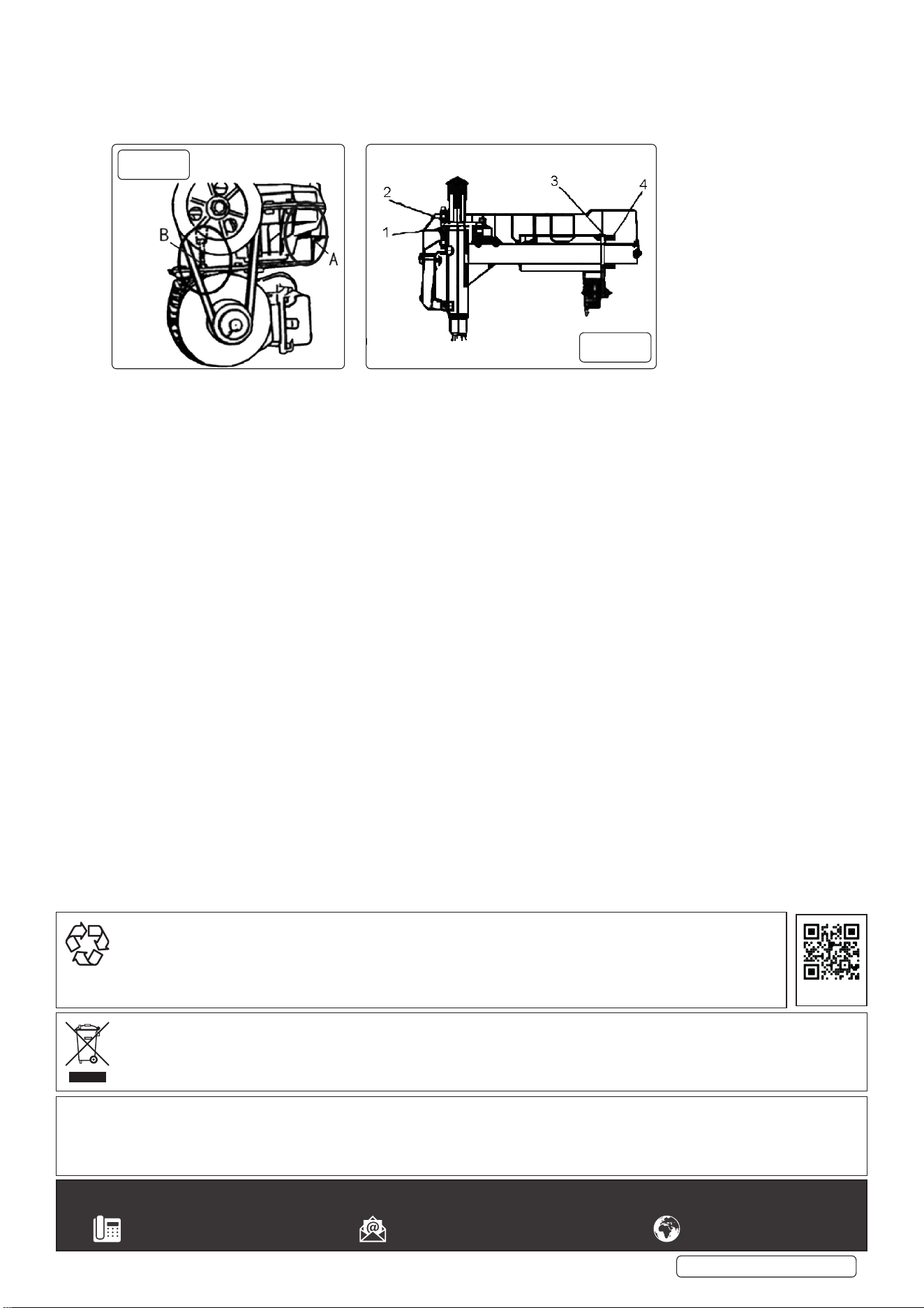
7.1.7. Check and adjust the tension of the drive belt. Adjust nuts A and B to obtain the correct tension g.32.
7.1.8. Check for any loose bolts.
7.2. Adjustment of the gap between the demounting tool and rim Verticalgap:adjustthehexagonallockplate.
7.2.1. Isolate the air supply and remove the vertical hexagonal shaft protective cover.
7.2.2. If the gap is too big, you can adjust the upper and lower nut at the front end of the hexagonal lock plate downwards. If the gap is too
small, adjust the upper and lower nut g.33.1/g.33.2 at the front end of the hexagonal lock plate upwards.
g.27
g.28
Original Language Version
© Jack Sealey Limited
g.26
g.29 g.30
g.31
TC10 Issue 4 (3,4) 28/08/24
7.3. HORIZONTAL GAP: ADJUST THE HORIZONTAL ARM LOCK PLATE
7.3.1. Isolate the air supply and remove protective cover at the upper end of the horizontal arm. Using a spanner to loosen the lock cap on
the M6 screw at the 2 ends. Adjust the M6 screw at two ends g.33.3 meanwhile push the horizontal shaft until it moves smoothly.
Then tighten the nut. Use the spanner to adjust the screw in the middle g.33.4. Tighten the horizontal arm and observe the gap.
When the gap is 2mm, lock the nut.
g.33
g.32
Original Language Version
© Jack Sealey Limited
Sealey Group, Kempson Way, Suffolk Business Park, Bury St Edmunds, Suffolk. IP32 7AR
01284 757500 sales@sealey.co.uk www.sealey.co.uk
Note: It is our policy to continually improve products and as such we reserve the right to alter data, specifications and component parts without prior
notice.
Important: No Liability is accepted for incorrect use of this product.
Warranty: Guarantee is 12 months from purchase date, proof of which is required for any claim.
ENVIRONMENT PROTECTION
Recycle unwanted materials instead of disposing of them as waste. All tools, accessories and packaging should be sorted,
taken to a recycling centre and disposed of in a manner which is compatible with the environment. When the product
becomes completely unserviceable and requires disposal, drain any fluids (if applicable) into approved containers and
dispose of the product and fluids according to local regulations.
WEEE REGULATIONS
Dispose of this product at the end of its working life in compliance with the EU Directive on Waste Electrical and Electronic Equipment
(WEEE). When the product is no longer required, it must be disposed of in an environmentally protective way. Contact your local solid
waste authority for recycling information.
TC10 Issue 4 (3,4) 28/08/24
REGISTER YOUR
PURCHASE HERE