DEHUMIDIFIER
MODELS 3PFD22, 3PFD35-2, 3PFD50, 3PFDP50
OWNER’S MANUAL


3
IMPORTANT SAFETY INSTRUCTION ............................................................................................. 4
IDENTIFICATION OF PARTS ...........................................................................................................13
POSITIONING THE UNIT ..................................................................................................................14
OPERATING INSTRUCTIONS ..........................................................................................................15
OTHER FEATURES ............................................................................................................................17
REMOVING THE COLLECTED WATER .........................................................................................18
CARE AND MAINTENANCE .............................................................................................................21
PREPARING FOR STORAGE ............................................................................................................21
TROUBLESHOOTING........................................................................................................................22
TABLE OF CONTENTS
IMPORTANT NOTE:
Read the manual carefully. Make sure to save this manual for future reference. Illustrations in this manual
are for explanatory purposes only, your actual product may look slightly dierent.
4
IMPORTANT SAFETY INSTRUCTION
READ THESE SAFETY PRECAUTIONS BEFORE INSTALLATION AND OPERATION.
For your safety, it is important that you read and follow the instructions in this manual to minimize the
risk of personal injury, re or electrical shock.
California Proposition 65 Warning
WARNING: Cancer and reproductive harm - P65warningns.ca.gov
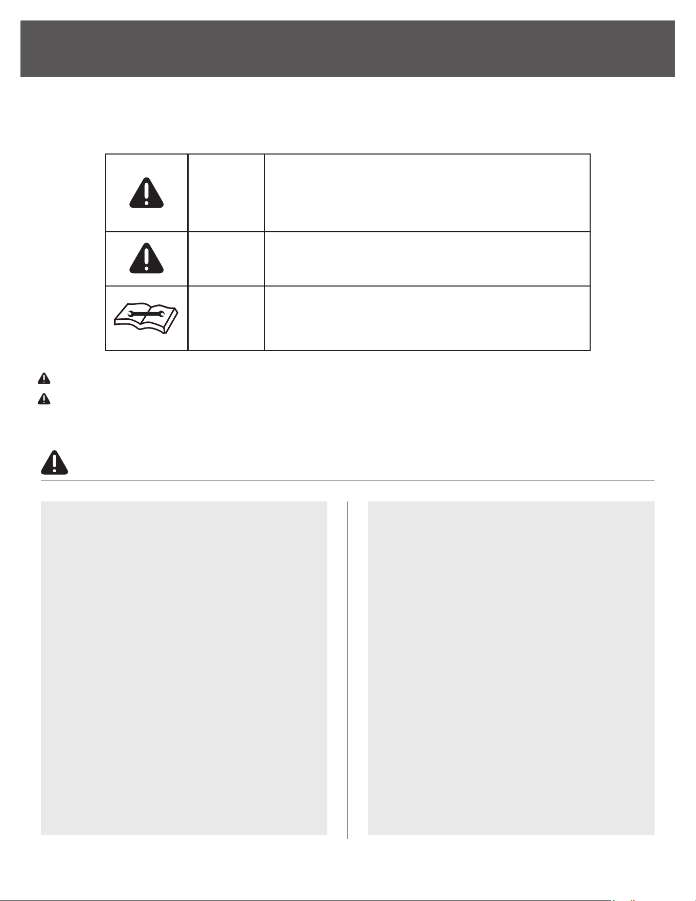
WARNING
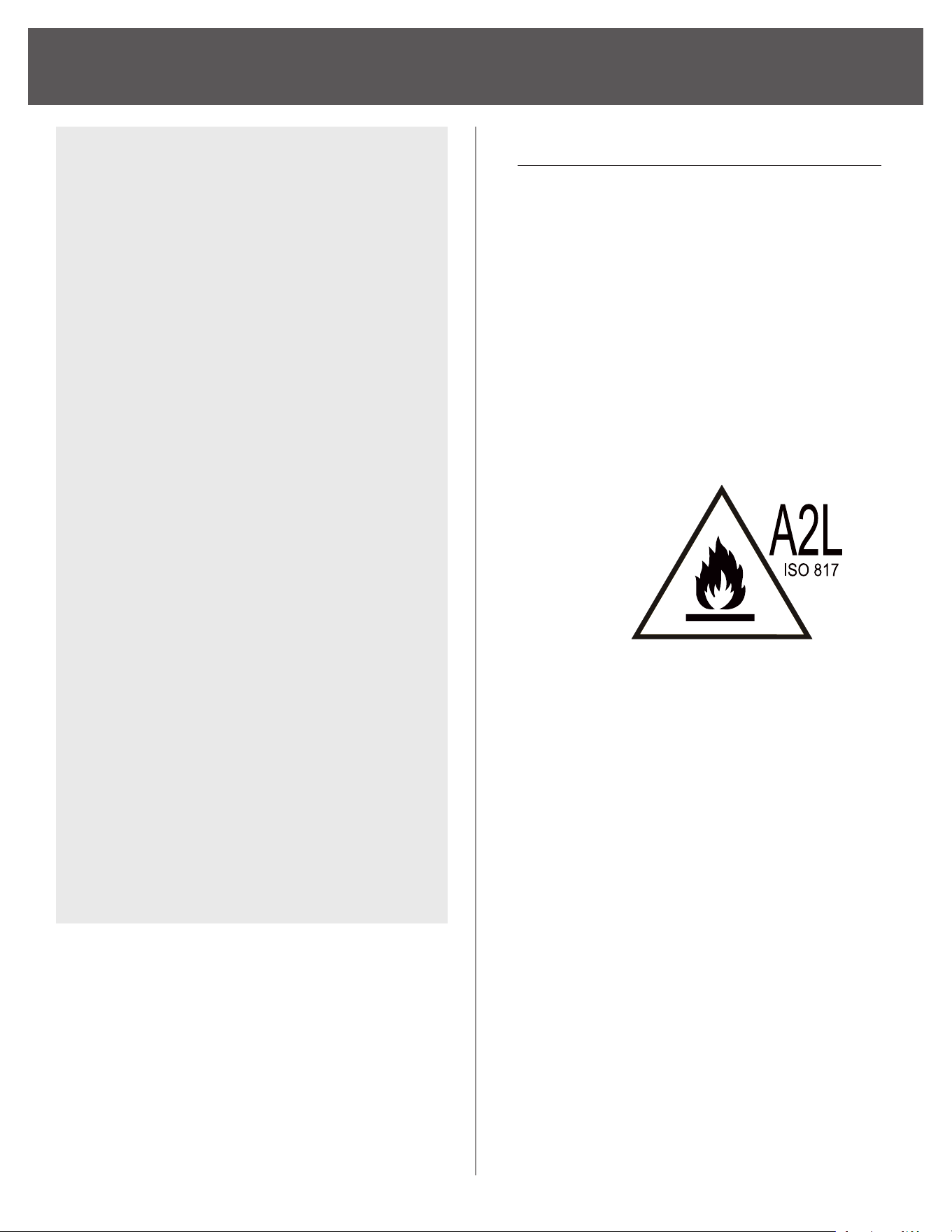
This symbol shows that this appliance uses a ammable
refrigerant. If a refrigerant leak occurs and is exposed to
an external ignition source, there is a risk of re.
This symbol shows that a service personnel should
be handling this equipment with reference to the
installation manual.
This symbol shows that the operation manual should be
read carefully.
WARNING
CAUTION
• This dehumidier is intended for indoor
residential us only and should not be used
for commercial or industrial applications.
Do not use outdoors
• Do not place the unit near a heat source or
other heat generating appliances such as
clothes dryer, heater or radiator
• Do not attempt to disassemble or repair
the unit by yourself.
• Do not use or store the dehumidier near
ammable gas or combustibles, such
as gasoline, benzene, thinner, or other
chemicals, etc.
• Do not drink or use the water collected
from the unit.
• Do not remove the water bucket during
operation.
• Do not use the unit in small cramped
spaces that are not well ventilated
• Do not store or use in areas where water
may splash onto the unit.
• Place the unit on a level, sturdy section of
the oor.
• Do not cover the intake or exhaust
openings.
• Never insert your nger or other foreign
objects into grills or openings. Take special
care to warn children of these dangers.
• Do not climb or sit on the unit.
• Always insert the lters securely. Clean
lter once every two weeks. If water enters
the unit, turn the unit o and disconnect
the power , contact a qualied service
technician.
• Do not place foreign objects on the unit.
• The dehumidier must be operated in an
enclosed area to be most eective.
CAUTION
5
IMPORTANT SAFETY INSTRUCTION
Stand dehumidier upright
for full 24 hours before
initial start up to allow
refrigerant to settle.
Always use and store
dehumidier in an
upright position.
• Close all doors, windows and other outside
openings to the room.
• When rst using the dehumidier, operate
the unit continuously 24 hours. Make sure
the plastic cover on the continuous drain
hose outlet is tted properly so there are
no leaks.
• This unit is designed to operate with a
working environment between 5ºC/41ºF
and 32ºC/90ºF, and between 30%(RH) and
80%(RH).
• The dehumidier should not be stored in a
room with continuously operating ignition
sources (for example: open ames, an
operating gas appliance or an operating
electric heater).
• Do not pierce or burn this dehumidier
• Be aware that the refrigerant contained
within this dehumidier is odorless
• Appliance should be installed, operated
and stored in a room with a oor area larger
than 50ft2.
• Compliance with national gas regulations
shall be observed.
• Keep ventilation openings clear of
obstruction.
• Servicing shall only be performed an
authorized service provider recommended
by the equipment manufacturer.
• Maintenance and repair requiring the
assistance of other skilled personnel shall
be carried out under the supervision of the
person competent in the use of ammable
refrigerants.
NOTE ABOUT FLUORINATED GASSES
• Continuous drainage uses gravity to
pull the Fluorinated greenhouse gases
are contained in hermetically sealed
equipment. For specic information on the
type, the amount and the CO2 equivalent in
tons of the uorinated greenhouse gas(on
some models), please refer to the relevant
label on the unit itself.
• Installation, service, maintenance and
repair of this unit must be performed by a
certied technician.
• Recycling must be performed by a certied
technician.
(Continued)
6
IMPORTANT SAFETY INSTRUCTION
WARNING
(For using R290/R32 refrigerant only)
• Servicing shall only be performed as
recommended by the equipment manufacturer.
Maintenance and repair requiring the assistance
of other skilled personnel shall be carried out
under the supervision of the person competent
in the use of ammable refrigerants.
• DO NOT modify the length of the power cord
or use an extension cord to power the unit.
• DO NOT share a single outlet with other
electrical appliances. Improper power supply
can cause re or electrical shock.
• Please follow the instruction carefully to
handle, install, clear, service the air conditioner
to avoid any damage or hazard. Flammable
Refrigerant R32 is used within air conditioner.
• When maintaining or disposing the air conditioner,
the refrigerant (R32) shall be recovered properly,
shall not discharge to air directly.
• Compliance with national gas regulations shall
be observed.
• Keep ventilation openings clear of obstruction.
• The appliance shall be stored so as to prevent
mechanical damage from occurring.
• A warning that the appliance shall be stored
in a well-ventilated area where the room size
corresponds to the room area as specied for
operation.
• Any person who is involved with working on
or breaking into a refrigerant circuit should
hold a current valid certicate from an
industry-accredited assessment authority,
which authorises their competence to handle
refrigerants safely in accordance with an
industry recognised assessment specication.
Examples for such working procedures are:
• breaking into the refrigerating circuit;
• opening of sealed components;
• opening of ventilated enclosures.
• No any open re or device like switch which
may generate spark/arcing shall be around air
conditioner to avoid causing ignition of the
ammable refrigerant used. Please follow the
instruction carefully to store or maintain the
air conditioner to prevent mechanical damage
from occurring.
• Do not use means to accelerate the defrosting
process or to clean, other than those
recommended by the manufacturer.
• The appliance shall be stored in a room without
continuously operating ignition sources (for
example: open ames, an operating gas
appliance) and ignition sourcesor (for example:
an operating electric heater) close to the
appliance. The appliance shall be stored in a
room without continuously operating ignition
sources (for example: open ames, an operating
gas appliance or an operating electric heater).
• Do not pierce or burn.
• Be aware that the refrigerants may not contain
an odour.
(Continued)
IMPORTANT NOTE:
Read this manual
carefully before installing or operating
your new air conditioning unit. Make sure
to save this manual for future reference.
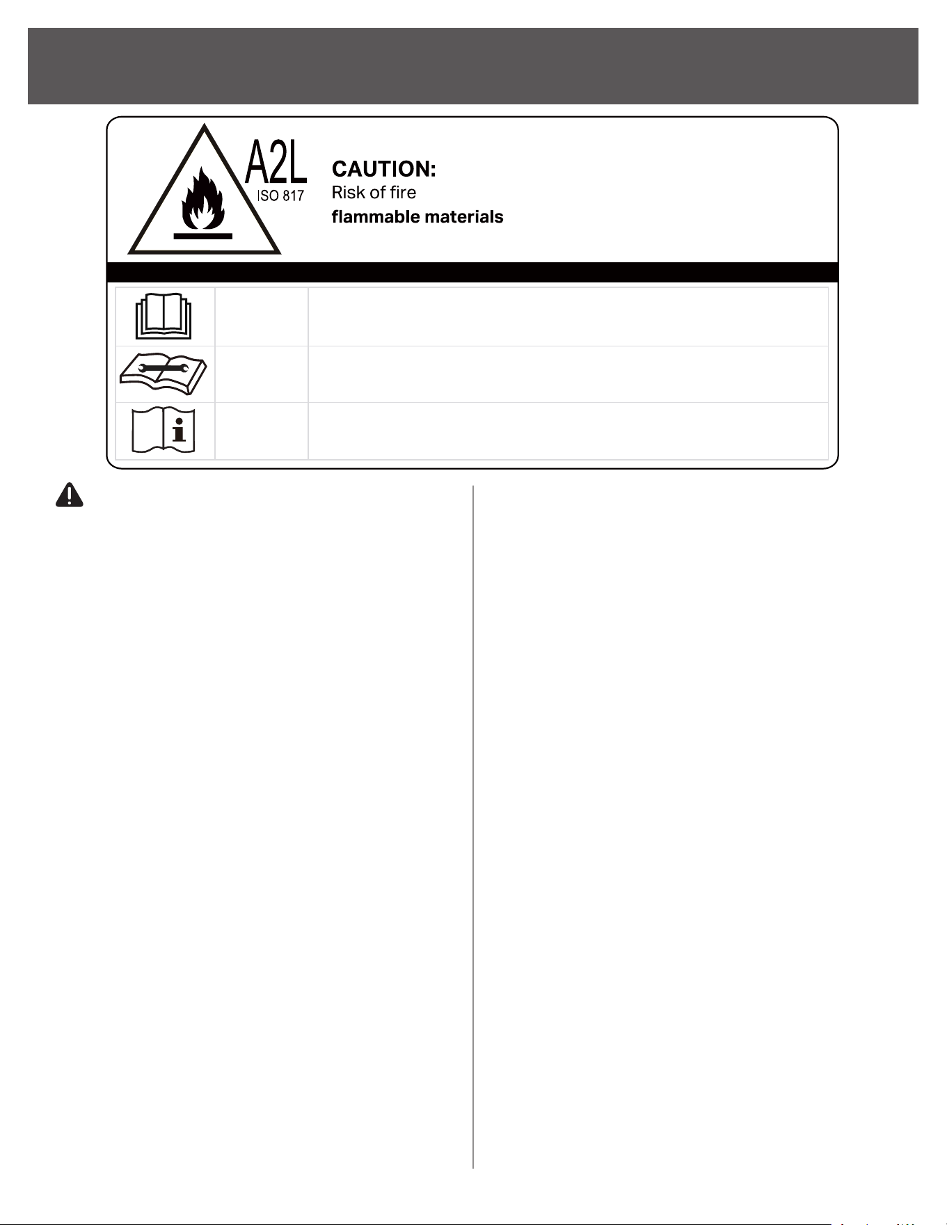
Explanation of symbols displayed on the unit
CAUTION
This symbol shows that the operation manual should be read carefully.
CAUTION
This symbol shows that a service personnel should be handling this equipment with
reference to the installation manual.
CAUTION
This symbol shows that information is available such as the operating manual or
installation manual.

7
IMPORTANT SAFETY INSTRUCTION
WARNING
(For using R290/R32 refrigerant only)
Transport of equipment containing
ammable refrigerants
• See transport regulations.
Marking of equipment using signs
• See local regulations.
Disposal of equipment using ammable
refrigerants
• See national regulations.
Storage of equipment/appliances
• The storage of equipment should be
in accordance with the manufacturer’s
instructions.
Storage of packed (unsold) equipment
• Storage package protection should be
constructed such that mechanical damage
to the equipment inside the package will not
cause a leak of the refrigerant charge.
• The maximum number of pieces of equipment
permitted to be stored together will be
determined by local regulations.
Information on servicing
1. Checking the area
• Prior to beginning work on systems
containing ammable refrigerants,
safety checks are necessary to ensure
that the risk of ignition is minimized. For
repair to the refrigerating system, the
following precautions shall be complied
with prior to conducting work on the
system.
2. Work procedure
• Work shall be undertaken under a
controlled procedure so as to minimize
the risk of a ammable gas or vapor
being present while the work is being
performed.
3. General work area
• All maintenance sta and others
working in the local area shall be
instructed on the nature of work being
carried out. Work in conned spaces
shall be avoided. The area around
the workspace shall be sectioned o.
Ensure that the conditions within the
area have been made safe by control of
ammable material.
4. Checking for presence of refrigerant
• The area should be checked with
an appropriate refrigerant detector
prior to and during work, to ensure
the technician is aware of potentially
ammable atmospheres. Ensure that
the leak detection equipment being
used is suitable for use with ammable
refrigerants, i.e. non-sparking,
adequately sealed or intrinsically safe.
5. Presence of a re extinguisher
• If any hot work is to be conducted
on the refrigeration equipment or
any associated parts, appropriate
re extinguishing equipment shall be
available to hand. Have a dry powder or
CO2 re extinguisher adjacent to the
charging area.
6. No ignition sources
• No person carrying out work in relation
to a refrigeration system which involves
exposing any pipe work that contains
or has contained ammable refrigerant
shall use any sources of ignition in such
a manner that it may lead to the risk of
re or explosion. All possible ignition
sources, including cigarette smoking,
should be kept suciently far away
from the site of installation, repairing,
removing and disposal, during which
ammable refrigerant can possibly be
released to the surrounding space. Prior
to work taking place, the area around
the equipment is to be surveyed to
make sure that there are no ammable
hazards or ignition risks. No Smoking
signs shall be displayed.
(Continued)

8
IMPORTANT SAFETY INSTRUCTION
WARNING
(For using R290/R32 refrigerant only)
7. Ventilated area
• Ensure that the area is in the open or
that it is adequately ventilated before
breaking into the system or conducting
any hot work. A degree of ventilation
shall continue during the period that
the work is carried out. The ventilation
should safely disperse any released
refrigerant and preferably expel it
externally into the atmosphere.
8. Checks to the refrigeration equipment
• Where electrical components are
being changed, they shall be t for the
purpose and to the correct specication.
At all times the manufacturer’s
maintenance and service guidelines
shall be followed. If in doubt consult the
manufacturer’s technical department for
assistance.
• The following checks shall be applied to
installations using ammable refrigerants:
• The charge size is in accordance
with the room size within which the
refrigerant containing parts are
installed.
• The ventilation machinery and
outlets are operating adequately
and are not obstructed.
• If an indirect refrigerating circuit is
being used, the secondary circuit
shall be checked for the presence
of refrigerant.
• Marking to the equipment continues
to be visible and legible. Markings
and signs that are illegible should
be corrected.
• Refrigeration pipe or components
are installed in a position where
they are unlikely to be exposed to
any substance which may corrode
refrigerant containing components,
unless the components are
constructed of materials which
are inherently resistant to being
corroded or are suitably protected
against being so corroded.
9. Checks to electrical devices
• Repair and maintenance to electrical
components should include initial safety
checks and component inspection
procedures. If a fault exists that could
compromise safety, then no electrical
supply shall be connected to the circuit
until it is satisfactorily dealt with. If the
fault cannot be corrected immediately
but it is necessary to continue
operation, an adequate temporary
solution should be used. This should be
reported to the owner of the equipment,
so all parties are advised.
• Initial safety checks should include:
• That capacitors are discharged: this
shall be done in a safe manner to
avoid possibility of sparking.
• That there no live electrical
components and wiring are exposed
while charging, recovering or
purging the system.
• That there is continuity of earth
bonding.
10. Repairs to sealed components
• During repairs to sealed components, all
electrical supplies shall be disconnected
from the equipment being worked upon
prior to any removal of sealed covers,
etc. If it is absolutely necessary to have
an electrical supply to equipment during
servicing, then a permanently operating
form of leak detection shall be located
at the most critical point to warn of a
potentially hazardous situation.
• Particular attention shall be paid to the
following to ensure that by working on
electrical components, the casing is not
altered in such a way that the level of
protection is aected. This shall include
damage to cables, excessive number
of connections, terminals not made to
original specication, damage to seals,
incorrect tting of glands, etc.
(Continued)

9
IMPORTANT SAFETY INSTRUCTION
• Ensure that seals or sealing materials
have not degraded such that they no
longer serve the purpose of preventing
the ingress of ammable atmospheres.
Replacement parts should be in
accordance with the manufacturer’s
specications.
NOTE: The use of silicon sealant may
inhibit the eectiveness of some
types of leak detection equipment.
Intrinsically safe components do not
have to be isolated prior to working
on them.
11. Repair to intrinsically safe components
• Do not apply any permanent inductive
or capacitance loads to the circuit
without ensuring that this will not exceed
the permissible voltage and current
permitted for the equipment in use.
Intrinsically safe components are the
only types that can be worked on while
live in the presence of a ammable
atmosphere. The test apparatus shall
be at the correct rating.
• Replace components only with parts
specied by the manufacturer. Other
parts may result in the ignition of
refrigerant in the atmosphere from a leak.
12. Cabling
• Check that cabling will not be subject
to wear, corrosion, excessive pressure,
vibration, sharp edges or any other
adverse environmental eects. The
check shall also take into account the
eects of aging or continual vibration
from sources such as compressors or
fans.
13. Detection of ammable refrigerants
• Under no circumstances, should
potential sources of ignition be used
in the searching for or detection of
refrigerant leaks. A halide torch (or any
other detector using a naked ame)
should not be used.
14. Leak detection methods
• The following leak detection methods
are deemed acceptable for systems
containing ammable refrigerants.
Electronic leak detectors shall be used
to detect ammable refrigerants, but
the sensitivity may not be adequate,
or may need re-calibration. (Detection
equipment should be calibrated in a
refrigerant-free area.) Ensure that the
detector is not a potential source of
ignition and is suitable for the refrigerant
used. Leak detection equipment should
be set at a percentage of the LFL of
the refrigerant and shall be calibrated
to the refrigerant employed and the
appropriate percentage of gas (25 %
maximum) is conrmed.
• Leak detection uids are suitable for
use with most refrigerants but the use of
detergents containing chlorine shall be
avoided as the chlorine may react with
the refrigerant and corrode the copper
pipework.
• If a leak is suspected, all naked ames
should be removed/ extinguished. If a
leakage of refrigerant is found which
requires brazing, all of the refrigerant
should be recovered from the system,
or isolated (by means of shut o valves)
in a part of the system remote from the
leak. Oxygen free nitrogen (OFN) should
then be purged through the system both
before and during the brazing process.
WARNING
(For using R290/R32 refrigerant only)
(Continued)

10
IMPORTANT SAFETY INSTRUCTION
15. Removal and evacuation
• When breaking into the refrigerant
circuit to make repairs or for any other
purpose conventional procedures
shall be used. However, it is important
that best practice is followed since
ammability is a consideration. Opening
of the refrigeration systems should not
be done by brazing.
• The following procedure shall be
adhered to:
• Remove refrigerant
• Purge the circuit with inert gas
• Evacuate
• Purge again with inert gas
• Open the circuit by cutting or
brazing.
• The refrigerant charge should be
recovered into the correct recovery
cylinders. The system should be ushed
with OFN to render the unit safe. This
process may need to be repeated
several times. Compressed air or oxygen
shall not be used for this task.
• Flushing should be achieved by breaking
the vacuum in the system with OFN
and continuing to ll until the working
pressure is achieved, then venting to
atmosphere, and nally pulling down to a
vacuum. This process shall be repeated
until no refrigerant is within the system.
• When the nal OFN charge is used,
the system shall be vented down to
atmospheric pressure to enable work to
take place. This operation is absolutely
vital if brazing operations on the
pipework are to take place.
• Ensure that the outlet for the vacuum
pump is not close to any ignition sources
and there is ventilation available.
16. Charging procedures
• In addition to conventional charging
procedures, the following requirements
should be followed. Ensure that
contamination of dierent refrigerants
does not occur when using charging
equipment. Hoses or lines should be
as short as possible to minimize the
amount of refrigerant contained in them.
• Cylinders should be kept upright.
• Ensure that the refrigeration system is
earthed prior to charging the system
with refrigerant.
• Label the system when charging is
complete (if not already).
• Extreme care should be taken not to
overll the refrigeration system.
• Prior to recharging the system, it
should be pressure tested with OFN.
The system should be leak tested on
completion of charging but prior to
commissioning. A follow up leak test
should be carried out prior to leaving the
site.
WARNING
(For using R290/R32 refrigerant only)
(Continued)

11
17. Decommissioning
• Before carrying out this procedure,
it is essential that the technician is
completely familiar with the equipment
and all its detail. It is recommended
good practice that all refrigerants
are recovered safely. Prior to the task
being carried out, an oil and refrigerant
sample should be taken in case analysis
is required prior to re-use of reclaimed
refrigerant. It is essential that electrical
power is available before the task is
commenced.
• Become familiar with the equipment
and its operation.
• Isolate the system electrically.
• Before attempting the procedure
ensure that:
• When breaking into the
refrigerant circuit to make
repairs or for any other
purpose, conventional
procedures should be used.
• Mechanical handling equipment
is available, if required, for
handling refrigerant cylinders.
• Personal protective equipment
is available and being used
correctly.
• The recovery process is
supervised at all times by a
competent person.
• Recovery equipment and
cylinders conform to the
appropriate standards.
• Pump down refrigerant system, if
possible.
• If a vacuum is not possible, make a
manifold so that refrigerant can be
removed from various parts of the
system.
• Make sure that cylinder is situated
on the scales before recovery takes
place.
• Start the recovery machine
and operate in accordance with
manufacturer’s instructions.
Do not overll cylinders. (No more
than 80 % volume liquid charge).
• Do not exceed the maximum
working pressure of the cylinder,
even temporarily.
• When the cylinders have been
lled correctly and the process
is completed, make sure that the
cylinders and the equipment are
removed from the site promptly and
all isolation valves on the equipment
are closed o.
• Recovered refrigerant should not be
charged into another refrigeration
system unless it has been cleaned
and checked.
WARNING
(For using R290/R32 refrigerant only)
(Continued)
IMPORTANT SAFETY INSTRUCTION

12
18. Labelling
• Equipment should be labelled stating
that it has been de-commissioned and
emptied of refrigerant. The label should
be dated and signed. Ensure that there
are labels on the equipment stating
the equipment contains ammable
refrigerant.
19. Recovery
• When removing refrigerant from
a system, either for servicing or
decommissioning, it is recommended
good practice that all refrigerants are
removed safely.
• When transferring refrigerant into
cylinders, ensure that only appropriate
refrigerant recovery cylinders are
employed. Ensure that the correct
number of cylinders for holding the total
system charge is available. All cylinders
to be used are designated for the
recovered refrigerant and labelled for
that refrigerant (i.e. special cylinders for
the recovery of refrigerant). Cylinders
shall be complete with pressure relief
valve and associated shut-o valves in
good working order. Empty recovery
cylinders are evacuated and, if possible,
cooled before recovery occurs.
• The recovery equipment shall be
in good working order with a set of
instructions concerning the equipment
that is at hand and shall be suitable for
the recovery of ammable refrigerants.
In addition, a set of calibrated weighing
scales shall be available and in good
working order.
• Hoses shall be complete with leak-
free disconnect couplings and in
good condition. Before using the
recovery machine, check that it is in
satisfactory working order, has been
properly maintained and that any
associated electrical components
are sealed to prevent ignition in the
event of a refrigerant release. Consult
manufacturer if in doubt.
• The recovered refrigerant shall be
returned to the refrigerant supplier in
the correct recovery cylinder, and the
relevant Waste Transfer Note arranged.
Do not mix refrigerants in recovery
units and especially not in cylinders. If
compressors or compressor oils are to
be removed, ensure that they have been
evacuated to an acceptable level to
make certain that ammable refrigerant
does not remain within the lubricant. The
evacuation process shall be carried out
prior to returning the compressor to the
suppliers. Only electric heating to the
compressor body should be employed
to accelerate this process. When oil
is drained from a system, it should be
carried out safely.
WARNING
(For using R290/R32 refrigerant only)
(Continued)
IMPORTANT SAFETY INSTRUCTION
13
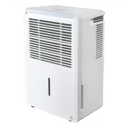
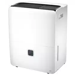
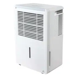
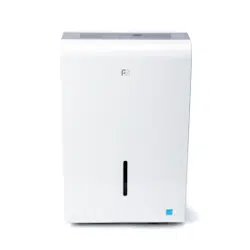
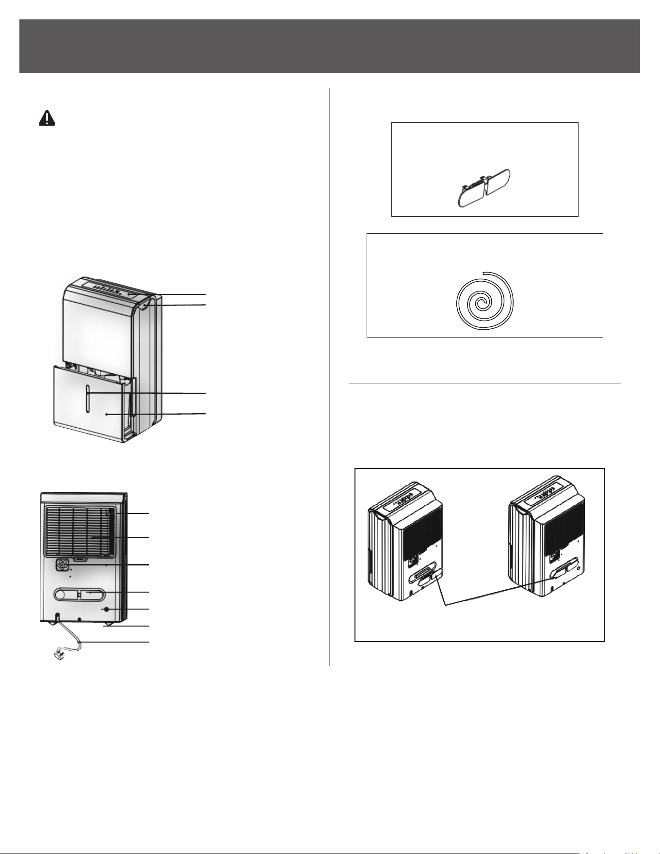
IDENTIFICATION OF PARTS
3PFDP50 only
1x 16FT Pump Drain Hose (ΦOD=1/4")
1x Power Cord Holder
(Shipped inside of bucket)
Fig 3
Clip the power cord handle
onto the unit.
Control Panel
Handle (both sides)
Water Bucket
Water Level Window &
Water Level Indicator
Side Air Outlet
Air Filter (lter is back panel)
Continuous Drain Hose Outlet
Power Cord Holder (shipped inside of bucket)
Pump Drain Hose Outlet (3PFDP50 only)
Caster
Power Cord
BEFORE YOU BEGIN
CAUTION
NOTE: The illustrations in the manual are
for explanation purpose only. The design
specications are subject to change without prior
notice. Your dehumidier may be slightly dierent.
The most up-to-date version of the manual can be
found at www.perfectaire.us
Consult with customer support for details.
ACCESSORIES
POWER CORD HOLDER INSTALLATION
Power cord holder will be shipped inside of the
water tank. During initial set up clip the power cord
holder onto the back side of the unit.
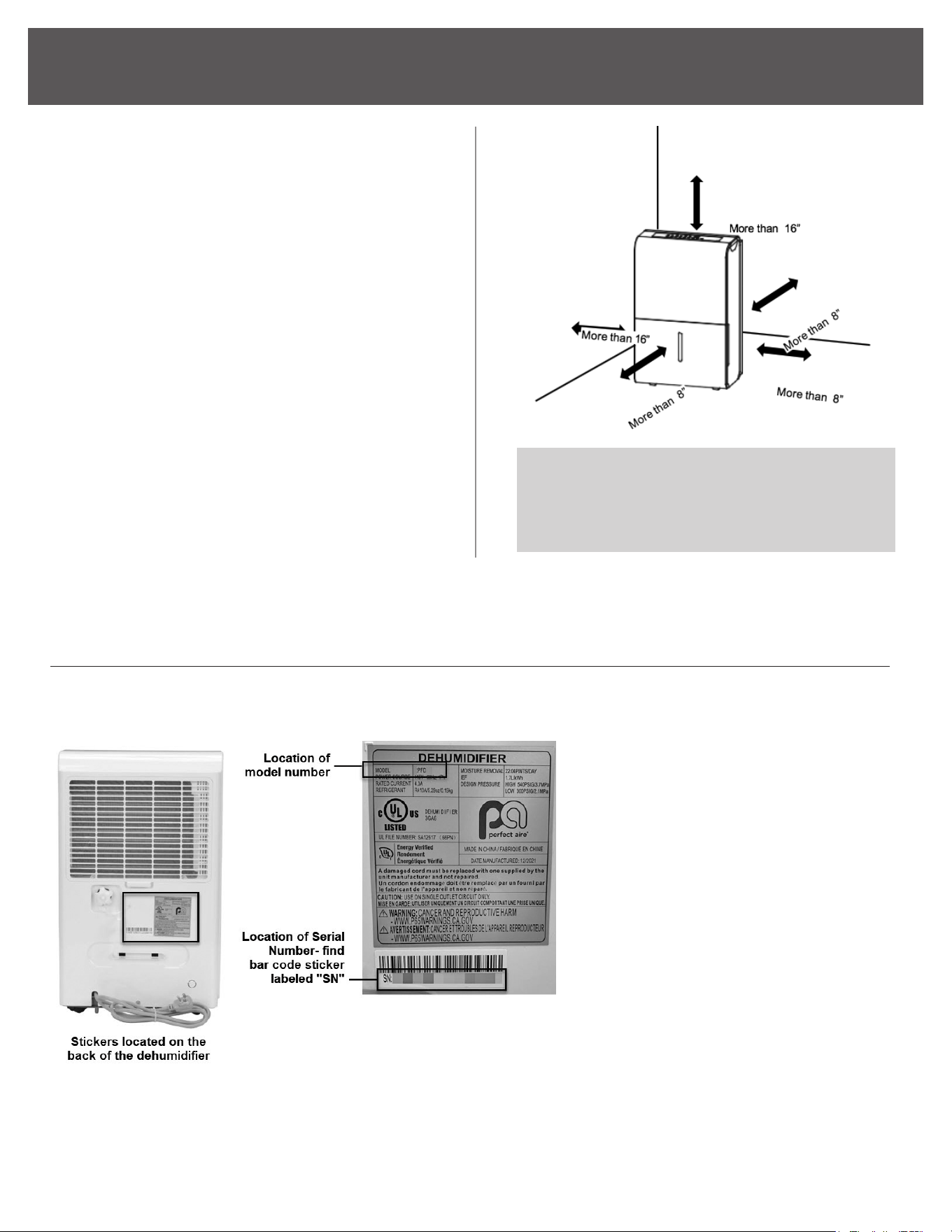
14
POSITIONING THE UNIT
Lockable casters are on the bottom of the unit.
Do not force the casters to move over carpet or
when there is water in the bucket as this may lead
to tripping and spillage.
• This dehumidier should not be used for
commercial or industrial applications.
• Place the dehumidier on a smooth, level oor
strong enough to support the unit with a full
bucket of water.
• For good air circulation and best performance,
allow at least 8 inches of air space on all sides
of the unit and a minimum of 16 inches of air
space at the side air outlet.
• Place the unit in an area where the
surrounding temperature will not fall below
41°F (5°C); Lower temperatures will cause
permanent damage to the unit and ice build
up on the coils.
The model number identies the
specic version or type of your
product, while the serial number is a
unique identier for your individual
unit. These details are essential for
any warranty claims, registration, or
technical support inquiries.
To register your dehumidier, please
visit www.newleafsc.net/perfectaire
and click "Register Your Product."
MODEL AND SERIAL NUMBER LOCATIONS
To nd the model and serial number of your product, please refer to the diagram below:
15
OPERATING INSTRUCTIONS
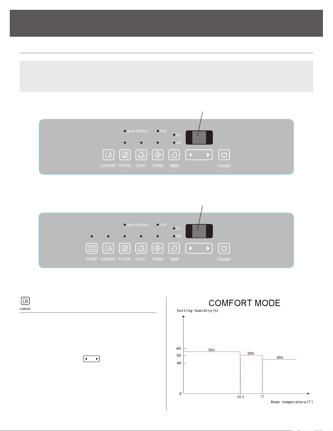
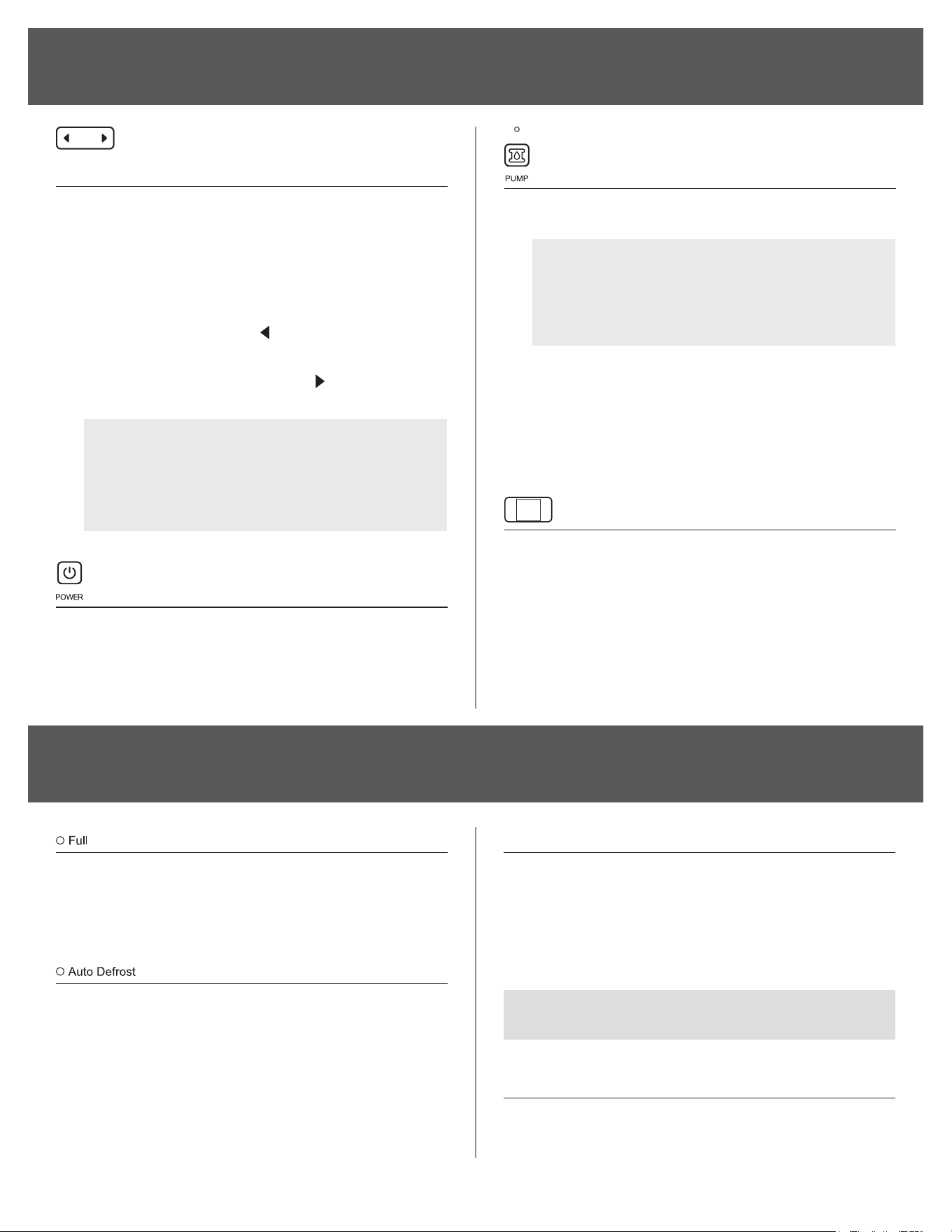
COMFORT BUTTON
• This dehumidication setting automatically
keeps the humidity level in the room between
45%-55% relative humidity (based on room
temperature).
• When operating in COMFORT MODE the touch
pad arrow buttons (
) will be deactivated
and you will NOT be able to set a desired
humidity level.
• To turn the comfort mode o and use the
touch pad arrows again, press the COMFORT
button until the indicator light turns o.
CONTROL PANEL FEATURES:
3PFD22, 3PFD35-2, 3PFD50
NOTE: Current Room Humidity will show
on display during regular use.
3PFDP50
NOTE: Current Room Humidity will show
on display during regular use.
NOTE: The following control panels are for explanation purpose only. The control panel of the unit you
purchased may be slightly dierent according to the models. Your machine may not contain some
indicators or buttons. The actual shape shall prevail.
16
(Continued)
FILTER BUTTON
• The FILTER light (clean lter indicator light)
will illuminate after 250 hours of fan motor
operation. This feature is a reminder to clean
the air lter for more ecient operation of the
dehumidier.
• Reset the timer, after cleaning the lter, by
pressing and holding the FILTER button until
the light turns o.
• If the unit is being used in a dusty and cold
environment like a basement or crawlspace
we recommend cleaning the lter more often.
CONTINUE BUTTON
• Press CONT. to activate the continuous
dehumidifying mode. In this mode, the
compressor and fan will run all the time.
• To turn the continuous feature o, press the
CONT. button until the indicator light turns o.
• When operating in CONTINUE mode the touch
pad arrow buttons
will be deactivated
and you will NOT be able to set a desired
humidity level.
TURBO BUTTON
• The Turbo button is to toggle between normal
fan speed and the highest fan speed (Turbo).
• Press to select either High or Normal fan speed.
• Set the unit to turbo by pressing the TURBO
button (green light illuminated) for maximum
moisture removal.
• When the desired humidity level has been reached,
press the TURBO button once more (green line
will extinguish) to return to normal operation.
TIMER BUTTON
Timer button is used in conjunction with the
(Humidity Control) buttons to initiate the
Auto start and Auto stop feature.
SETTING THE TIMER
• The TIMER button can be used to set a desired
ON or OFF time for the dehumidier. The
ON time or OFF time setting can only be set
in increments of 0.5 hr. up to 10 hrs. and 1hr
increments from 10 to 24 hrs.
NOTE:
• If the unit is o, the timer “On” indicator
be the rst to illuminate.
• If the dehumidier is on, the timer “O”
indicator will rst illuminate.
• Toggle between Timer On and Timer
O by pressing the TIMER button.
• Press the TIMER button, the timer O or On
indicator light illuminates. This indicates the
auto stop/start program is initiated.
• Press or hold the
or
button to change the
desired stop/start time by 0.5 hour increments,
up to 10 hours, then at 1 hour increments from
10 to 24 hours from the time the feature is set.
The control will count down the time remaining
until the dehumidier stops/starts.
• Press the TIMER button again the timer On
indicator light illuminates. This indicates the
auto start program is initiated.
• Press or hold the
or
button to change the
desired start time by 0.5hour increments, up to
10 hours, then at 1 hour increments from 10 to
24 hours from the time the feature is set. The
control will count down the time remaining until
starts.
• When the Timer On & Timer O times are set,
within the same program sequence, both On
and O indicator lights will illuminate indicating
both On and O times are programmed.
• Turning the unit On or O at any time or
adjusting the timer setting to 0.0 will cancel the
Auto Start/ Stop function.
• If the water bucket is full and the LED display
window displays P2, the Auto Start/Stop
function will also be canceled.
OPERATING INSTRUCTIONS
17
OPERATING INSTRUCTIONS
HUMIDITY SET CONTROL
LEFT/RIGHT (BUTTONS)
• The humidity set control buttons are used to
set the desired humidity level.
• The humidity level can be set between 35% RH
(Relative Humidity) to 85% RH (Relative
• Humidity) in 5% increments.
• For drier air, press the
button to the desired
lower RH % level.
• For more humid air, press the
button to the
desired higher RH% level
NOTE: The machine will not run
compressor or start dehumidifying area
the until the room humidity percentage
rises higher than set percentage.
POWER BUTTON
• Press to turn the dehumidier on and o.
• Dehumidier will power on and automatically
resume last used settings.
PUMP BUTTON (3PFDP50 ONLY)
• Press to activate the pump operation.
NOTE: Make sure the pump drain hose is
installed into the unit and the continuous
drain hose is disconnected from the unit
before the pump operation is activated.
• Refer to the next pages for removing the
bucket and discarding the collected water.
• Do not use this operation when the outdoor
temperature is at or below 32°F (0°C)
LED DISPLAY
Depending on the feature selected, the LED
Display will show the current relative humidity level
in the room ( 35% - 85%), the auto start/stop
setting (0.0~24) while setting the timer function,
as well as the desired humidity level setting for
the dehumidier. The accuracy of the relative
humidity reading in the room is ±5% for humidity
levels between 30% and 90%.
OTHER FEATURES
BUCKET FULL LIGHT
The Full indicator light will be illuminated when
the bucket is full and ready to be emptied or if the
bucket was not put back in place correctly.
AUTO DEFROST
The unit will automatically enter auto defrost mode
when frost/ice builds up on the evaporator coils.
The compressor will cycle o and the fan will
continue to run until the frost disappears. During
this operation the Auto Defrost indicator light will
be illuminated.
AUTO SHUT OFF
The dehumidier shuts o when the bucket is full,
or when the bucket is removed or is not replaced
in the proper position. The compressor will also
automatically shut o when the desired humidity
level is reached. The fan will continue to operate
for an additional 3 minutes.
NOTE: 3PFDP50 models will activate the water
pump when bucket is full.
AUTO-RESTART
In the event of an unexpected power interruption,
the unit will automatically restart with the previous
function setting once the power is restored.
(Continued)
18
REMOVING THE COLLECTED WATER
There are three ways to remove collected water:
1
USING THE BUCKET
• If the unit is OFF, and the bucket is full, the
FULL indicator light will illuminate.
• If the unit is ON, and the bucket is full, the
compressor and fan will turn o.
Then, the full indicator light will illuminate and
the LED display will show code P2.
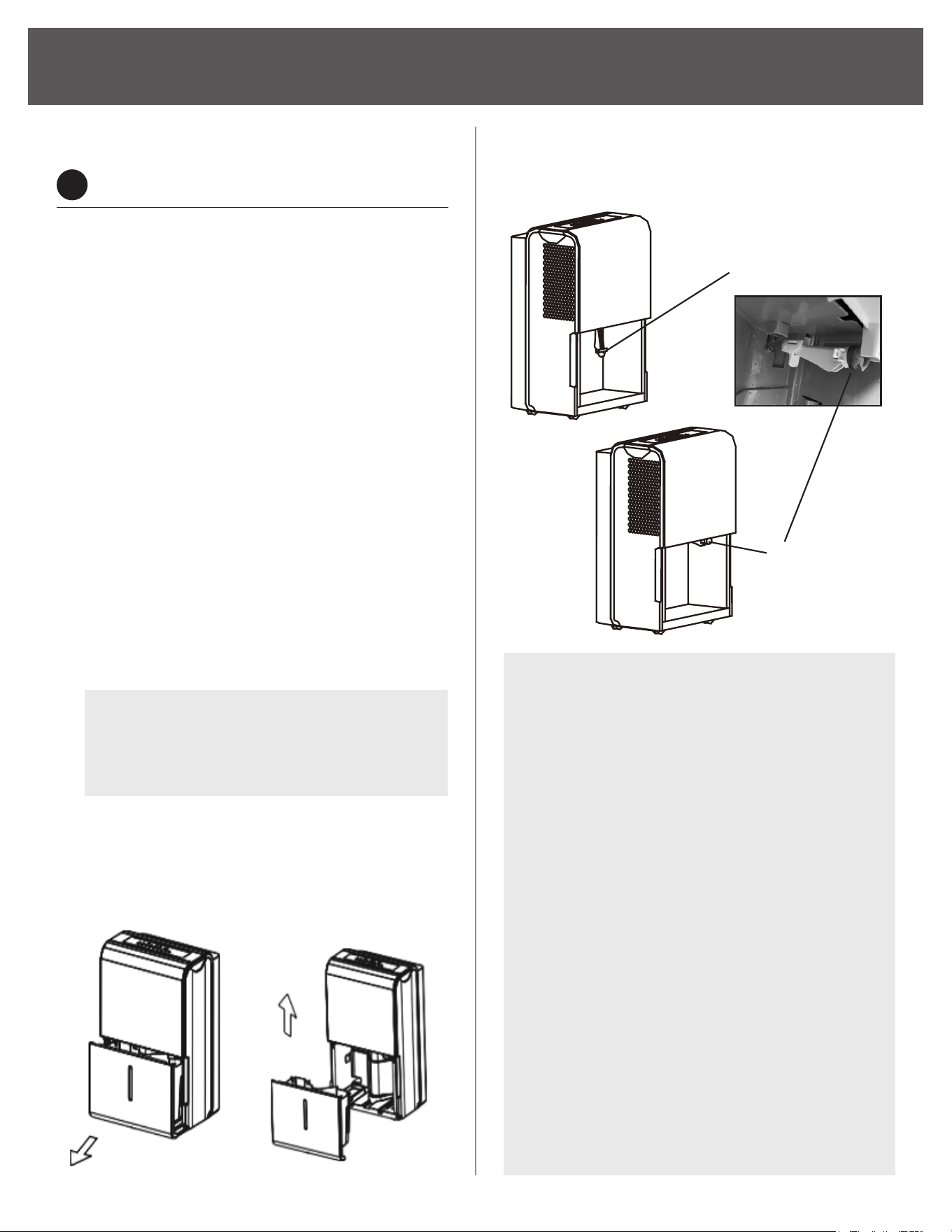
EMPTY AND REINSERT THE BUCKET...
• Grip the left and right bucket handles securely,
and carefully pull out straight so water does
not spill. Do not place the bucket on the oor
because the bottom of the bucket is uneven
and the water may spill. Code EB will show on
the display panel when the bucket is removed.
Empty the water from bucket into a drain.
• The bucket must be replaced carefully and
securely for the dehumidier to operate. The
code EB will disappear from the display panel
and unit will re-start with the last used settings
after the bucket is returned to its correct
position.
1. Partially remove the bucket
2. Hold both sides of the bucket with even strength,
and completely remove from the unit and pour
out the water.
NOTE:
For 3PFDP50 model only, before
reinserting the bucket, the pump arm on
the right-side of the bucket area will need
to be lifted back up into position.
NOTE:
• When you remove the bucket, do not touch
any parts inside the unit. Doing so may
damage the product.
• Be sure to push the bucket gently all the
way into the unit. Banging the bucket
against anything or failing to push it in
securely may cause the unit not to operate.
• If the pump hose drops when you remove
the bucket, you must reinstall the pump
hose properly to the unit before replacing
the bucket into the unit.
• If there is some water in the unit after
you remove the unit after you remove the
bucket, you must dry it.
• If the bucket is removed while the unit is
running, the compressor and the fan will
turn o, the unit will beep 8 times and the
digital display will show P2.
• If the bucket is removed while the unit is
turn o, the unit will beep 8 times and the
digital display will show P2.
3PFDP50 MODELS ONLY:
Pump arm needs to be pushed back up into place
before reinserting the bucket:
Pump arm drops
Reinstall pump
arm properly
19
(Continued)
REMOVING THE COLLECTED WATER
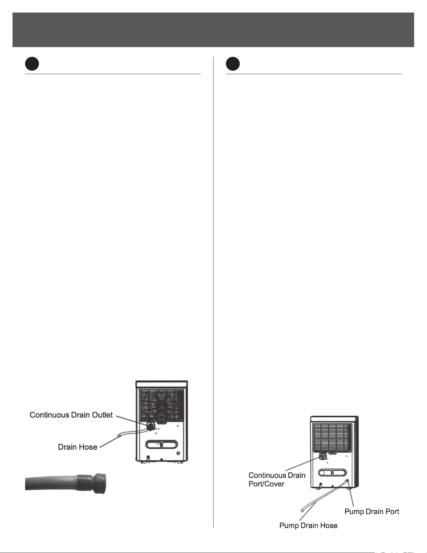
2
CONTINUOUS DRAINING
Continuous drainage uses gravity to pull the water
out of the unit through a hose. A white screw cap
covers the continuous drain outlet; Unscrew it to
attach the continuous drain hose. The drainage
outlet hose must be sealed with the provided cap
when not in use. Failure to tightly seal the cap if
drain is not in use will cause leaking water.
• A maximum 6ft length garden hose
(ld≥Φ5/16′′, not included) with a female
threaded end (ID:M=1′′, not included) can be
used for the continuous drainage option. The
unit is not designed to secure a vinyl hose and
can cause leaking water.
• The continuous drain hose must be placed in
a downward angle at all time. A maximum 6ft
length will prevent backups on days of extra
humidity. Any upward angles or sharp bends
will cause the water to either become stuck
inside the hose or backup into the unit.
• A small water pan inside of the unit is
already installed on the optional angle to
route water out as soon as the unit creates
it. Dehumidiers are designed to be used
on leveled oors. If the unit is placed on an
unleveled or even slightly forward angle the
water will run into the bucket as a backup.
• Basement oors will always have a slight
downward slope towards the oor drain.
Place the unit so the back panel is facing
the oor drain.
3
PUMP DRAINAGE (3PFDP50 ONLY)
Water pumps provide much more exibility for
drainage options. It can pump water vertically
(straight up) a maximum height of 16FT and as far
as 16FT length; This is ideal for routing water out
a window, to a distant oor drain, or into a sink so
the unit can stay on a secure oor. The pump turns
on when the water bucket is completely full and
will expel 32oz of water, about half of the bucket,
before stopping.
• A maximum 16FT length hose (ΦOD=1/4”,
included) can be used for the pump option.
• To install the hose, make sure it is pushed into
the pump drain outlet to a depth of at least 1/2
inch (approx. 15 mm). Once the hose is installed
to the proper depth, the holder will lock it in
place. The other end of the hose is placed in a
oor drain or the location water will drain.
• Then, press the PUMP button on the display
panel to turn on the water pump feature.
The pump will activate only when the pump
light indicator on the display is on and the
water bucket is full. It will expel 32oz of water,
about half the bucket, and then turn o.
Recommend to completely empty the water
bucket and clean it every week to prevent
stagnant water and mold growth.
• The hose should always be removed when the
pump feature is not being used. To remove the
hose, rmly press on the plastic ring around
the pump hose outlet and gently pull on the
hose. Do NOT force the hose to detach from
the holder by only pulling on it; This will cause
permanent damage to the unit. Be aware,
residual water may expell from the unit when
removing the hose.
Continuous drain hose (ld≥Φ5/16′′, not included)
with a female threaded end (ID:M=1′′, not included.)

20
(Continued)
REMOVING THE COLLECTED WATER
CAUTION
The pump operation light will blink will at 1Hz if
there is an operational failure of the pump. Please
turn o the unit and unplug the power.
CHECK THE FOLLOWING THINGS:
• Remove the bucket from the unit, take down
the pump arm and clean the pump arm mesh
lter.
• Check that the pump drain hose is not kinked
or blocked.
• Check that the vertical height of the pump
hose is at most 16ft. Beyond 16ft, the pump
will not properly function.
• Empty the water of the bucket.
• Reinstall the pump hose if it is disconnected
from the unit and properly reinstall the bucket.
• Unplug the device and allow a 3-minute interval
before reconnecting and turning it on again. If
the error repeats, call for service.
NOTE: The pump may make a noticeable
sound for 3~5 minutes on startup. It is a
normal phenomenon.
CAUTION
Do not use this operation when the outdoor
temperature is equal to or less than 32°F (0°C),
otherwise water will freeze inside the hose
resulting in unit failure.
Simultaneously pull out hose.
Push in on the
edge of the
pump inlet
21
CARE AND MAINTENANCE
Turn the dehumidier o and unplug it from the
wall outlet before cleaning.
• Use water and a mild detergent. Do not use
bleach or abrasives.
• Do not splash water directly onto the main unit.
Doing so may cause an electrical shock, cause
the insulation to deteriorate, or cause the unit
to rust.
• The air intake and outlet grilles get soiled
easily; use a vacuum attachment or brush
to clean.
• Every week, clean the bucket to prevent
growth of mold, mildew and bacteria.
NOTE:
Do not use a dishwasher to clean
the bucket. After cleaning, the bucket must
be replaced and securely seated for the
dehumidier to operate.
1. Partially ll the bucket with clean water and
add a little mild detergent.
2. Swish it around in the bucket.
3. Empty and wipe down the inside of bucket with
a soft cloth.
4. Rinse.
CAUTION
Do not operate the dehumidier without a lter
because dirt and lint will clog it and reduce
performance
When not using the unit for long time periods:
1. After turning o the unit, wait one day before
emptying the bucket to catch any residual
water.
2. Clean the main unit, water bucket and air lter.
3. Allow the entire assembly to air dry.
4. Wrap the cord with onto the power cord handle
5. Store the unit upright in a dry, well-ventilated
place.
PREPARING FOR STORAGE
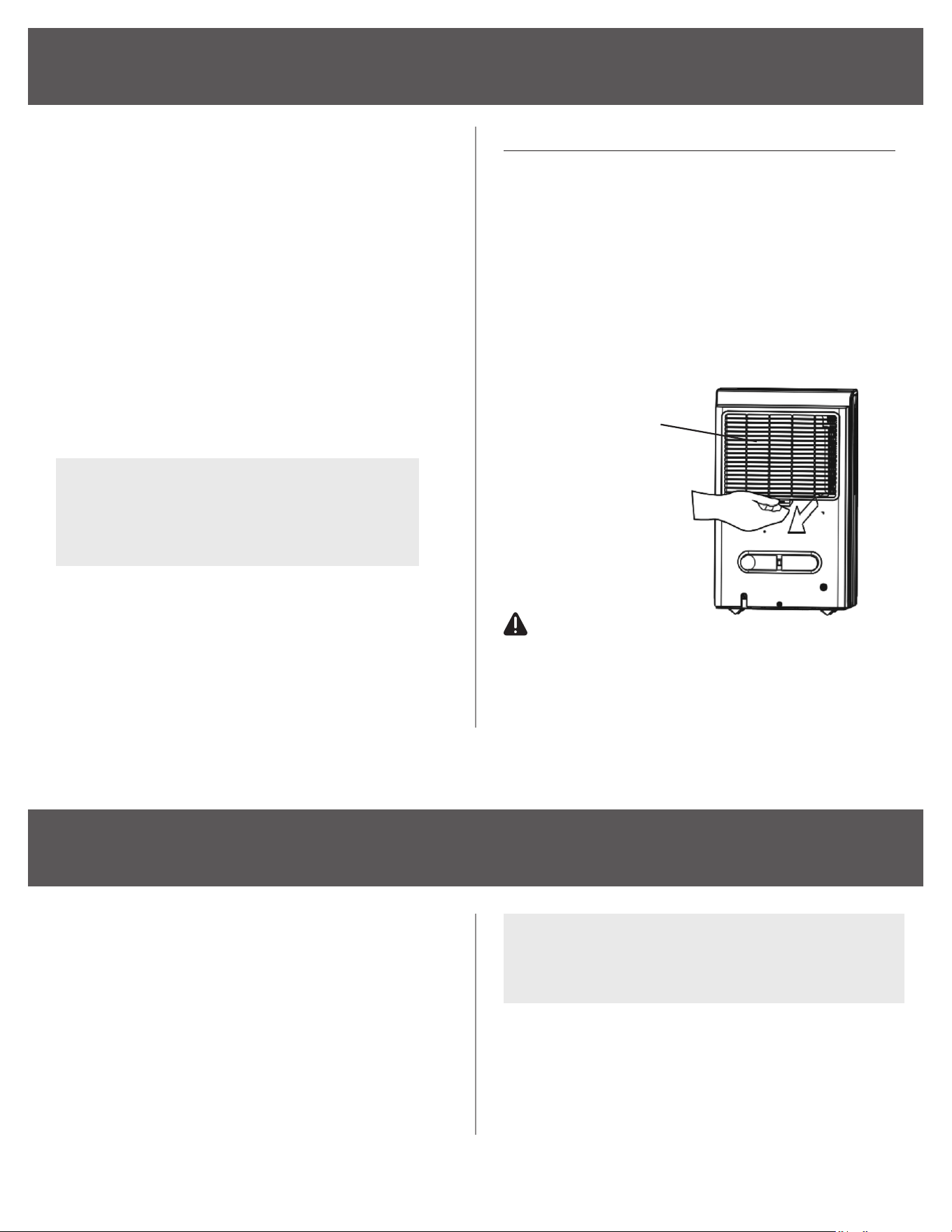
CLEANING THE AIR FILTER
• THE FILTER IS INTEGRATED WITH THE
BACK PANEL OF THE UNIT AND NOT A
SEPARATE ITEM.
• Clean the lter every two weeks based on
normal operating conditions.
• To remove the lter, pull lter outwards.
• Wash the lter with clean water then dry.
• Re-install the lter, replace bucket.
Air lter is the
back panel
NOTE: Dehumidier should always be stored
upright! Never store dehumidier upside down,
on side, or any other position other than upright.

22
TROUBLESHOOTING
Before calling for service, review the chart below.
Problem What to check
Unit does not start
Make sure the dehumidier s plug is pushed completely into the outlet.
Check the house fuse/circuit breaker box.
Dehumidier has reached its preset level or bucket is full.
Water bucket is not in the proper position.
Dehumidier does not
dry the air as it should
Did not allow enough time to remove the moisture. Please allow a full 24 hours to pass
before expecting to see a change in room humidity level or collected water.
Make sure there are no curtains, blinds or furniture blocking the front or back of the
dehumidier.
Make sure the machine's set humidity percentage is lower than the current room's humidity
percentage. The machine can then be run on CONT. mode for 24 hours to test.
Check that all doors, windows and other openings are securely closed.
Room temperature is too low , below 5 °C (41° F).
There is a kerosene heater or something giving o water vapor in the room.
The unit makes a loud
noise when operating
The air lter is clogged.
The unit is tilted instead of upright as it should be.
The oor surface is not level.
Frost appears on the coils This is normal. The dehumidier has Auto defrost feature.
Water on oor
Hose to connector or hose connection may be loose.
Intend to use the bucket to collect water, but the back drain plug is removed.
Make sure dehumidier is on a level surface; An unleveled oor can cause the unit to lean to
one side and leak water from the internal tray.
The pump operation
on light blinks at 1Hz
Clean the lter of the pump arm inside of the bucket area.
Check the pump hose is not kinked or blocked.
Empty the water of the bucket.
Unplug the machine, remove the pump hose.
A dry Qtip can be used to clean dust from the pump hose inlet.
ES - Tube Temperature sensor
of the evaporator error
Unplug the unit and plug it back in. If error repeats, call for service.
AS -Humidity sensor error Unplug the unit and plug it back in. If error repeats, call for service.
P2 - Bucket is full Empty the bucket and replace it in the right position
EB - Bucket is removed Replace the bucket in the right position.


844-4PA-AIRE | 844-472-2473 | support@perfectaire.us
CANADA SUPPORT 877-997-2473 | supportcanada@perfectaire.us
www.perfectaire.us
5401 Dansher Road
Countryside, IL 60525
Printed in China | 0823_M075
THANK YOU FOR YOUR PURCHASE!
We’d love to hear how you are enjoying your Perfect Aire product!
Please take a minute to tell us (and others) about your experience.
Thanks (again!)
SCAN CODE TO
LEAVE A REVIEW