Assembly and Operating Instructions
FOR OUTDOOR USE ONLY
7000 SERIES
BMF7645SA,BMF7655SA
BMG7642SA,BMG7652SA
AUSTRALIA / NEW ZEALAND
2 CONTENTS
Important safety instructions............................................ ...........3
BMF7645SA product description / dimensions ..........................4
BMF7655SA product description / dimensions ..........................6
BMG7642SA product description / dimensions ..........................8
BMG7652SA product description / dimensions ........................10
Gas specifications .......................................................................12
BMF7645SA & BMF7655SA assembly ......................................11
BMG7642SA & BMG7652SA assembly ......................................36
Natural gas installation..............................................................53
Installation ..................................................................................59
Rain baffle installation ...............................................................60
Side burner operating instruction .............................................62
Installation warnings .................................................................63
Gas specifications and mobile restraint ....................................65
Care and maintenance ..............................................................68
Mounting enclosure guidelines .................................................69
Operating instructions ...............................................................70
Troubleshooting .........................................................................73
Notes ........................................................................................... 74
Warranty .....................................................................................75
Please read the user manual carefully and store in a handy
place for later reference.
The symbols you will see in this booklet have these
meanings:
WARNING
This symbol indicates information concerning your
personal safety.
CAUTION
This symbol indicates information on how to avoid damaging
the appliance.
IMPORTANT
This symbol indicates tips and information about use
of the appliance.
ENVIRONMENT
This symbol indicates tips and information about economical
and ecological use of the appliance.
Dear Customer,
Congratulations and thank you for choosing our barbecue.
We are sure you will find it a pleasure to use. Before you use
the barbecue, we recommend that you read through the
relevant sections of this manual, which provide a description
of your appliance and its functions.
To avoid the risks that are always present when you use
an appliance, it is important that the appliance is installed
correctly and that you read the safety instructions carefully to
avoid misuse and hazards.
We recommend that you keep this instruction booklet for
future reference and pass it on to any future owners.
After unpacking the appliance, please check it is not
damaged. If in doubt, do not use the appliance but contact
your local customer care centre.
This appliance complies with requirements of Australian
Standards AS5263.
Conditions of use
These important notes apply to your appliance, failure to
adhere to these conditions of use may affect your ability to
make a claim under the manufacture’s warranty.
• THIS APPLIANCE MUST BE SERVICED ONLY BY A
QUALIFIED LICENCED PERSON.
• THIS PRODUCT IS INTENDED FOR PERSONAL,
DOMESTIC OR HOUSEHOLD USE ONLY, NOT
COMMERCIAL USE.
• THIS PRODUCT IS INTENDED FOR OUTDOOR USE
ONLY.
• THIS PRODUCT MUST BE INSTALLED, OPERATED AND
MAINTAINED AS PER THE INSTRUCTIONS.
Please ensure you read both instruction manuals fully
before you call for service, or a full service fee could
be applicable.
Record model and serial number here:
Model number:
Serial number:
PNC:
CONTENTSCONGRATULATIONS
IMPORTANT INFORMATION THAT MAY
IMPACT YOUR MANUFACTURER’S WARRANTY
Adherence to the directions for use in this manual
is extremely important for health and safety. Failure
to strictly adhere to the requirements in this manual
may result in personal injury, property damage
and affect your ability to make a claim under the
BeefEater manufacturer’s warranty provided with
your product. Products must be used, installed and
operated in accordance with this manual. You may
not be able to claim on the BeefEater manufacturer’s
warranty in the event that your product fault is due to
failure to adhere this manual.
3SAFETY
Please read the user manuals carefully and store in a
handy place for later reference.
IMPORTANT
Important – check for any damages or marks
If you find the barbecue is damaged or marked, you must
report it within 7 days if you wish to claim for damage/marks
under the manufacturer’s warranty. This does not affect
your statutory rights.
ENVIRONMENT
Information on disposal for users
• Most of the packing materials are recyclable.
Please dispose of those materials through your local
recycling depot or by placing them in appropriate
collection containers.
• If you wish to discard this product, please contact
your local authorities and ask for the correct method
of disposal.
WARNING
This appliance must be serviced only by a qualified licensed
person.
Improper installation, adjustment, alteration or
maintenance can cause injury or property damage and
may affect your ability to claim under the manufacturer’s
warranty.
Please contact your nearest BeefEater Service Department
for additional information or assistance from an approved
installer.
Notes to the installer
• After the barbecue is removed from the packaging take
care to protect the gas hose connection from damage.
• Wear gloves when assembling the barbecue to protect
your hands from cuts
• This manual must remain with the owner for future
reference.
WARNING
• Do not lean over barbecue when lighting
• Do not leave the barbecue unattended when alight
• Do not delay lighting once the gas has been turned on
• Do not store or use aerosol cans in the vicinity of the
barbecue
• Do not store or use flammable liquids or flammable
materials in the vicinity of this barbecue
• Do not use caustic or abrasive based cleaners on the
barbecue
• Do not attempt to dismantle or adjust the control valves
• Do not attempt to dismantle or adjust the regulator
• Do not test for leaks with a naked flame
• Do not modify the construction of this appliance or
modify the injector orifice size
• Do not place articles on or against this appliance
• Do not obstruct any ventilation of the barbecue
• Do not allow children to operate or play near the
barbecue
Failure to adhere to the above warnings may cause injury
or property damage and affect your ability to make a claim
under the manufacturer’s warranty.
CAUTION
This appliance is set up for LPG gas and is labelled
accordingly. A natural gas conversion kit is available as an
accessory if required. Conversion of this unit to natural gas
must be carried out by a qualified licensed person and a
Certificate of Compliance must be issued to the owner at the
completion of the installation and conversion.
IMPORTANT
BeefEater barbecues are approved for OUTDOOR USE ONLY
and must not be used in a building,garage or any other
enclosed area.
• BeefEater barbecues must not be used inside
recreational vehicles or boats
• Read instructions thoroughly before operating this
barbecue
• Save this manual for future reference
• Always use the barbecue on a flat, level surface
• Some foods produce flammable fats and juices. Regular
cleaning is essential.
• Attend an operating barbecue at all times. Damage
caused by fat & grease fires is not covered by warranty
• When not in use keep barbecue dry and covered
WARNING
If you smell gas:
1. Shut off gas to the appliance
2. Extinguish any open flame
3. Open hood
4. If odour continues, immediately call your gas supplier
or your fire department
For your safety
1. Do not store or use gasoline or other flammable
vapours or liquids in the vicinity of this or any other
appliance
2. An LPG cylinder not connected for use shall not be
stored in the vicinity of this or any other appliance
IMPORTANT SAFETY INSTRUCTIONS
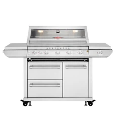
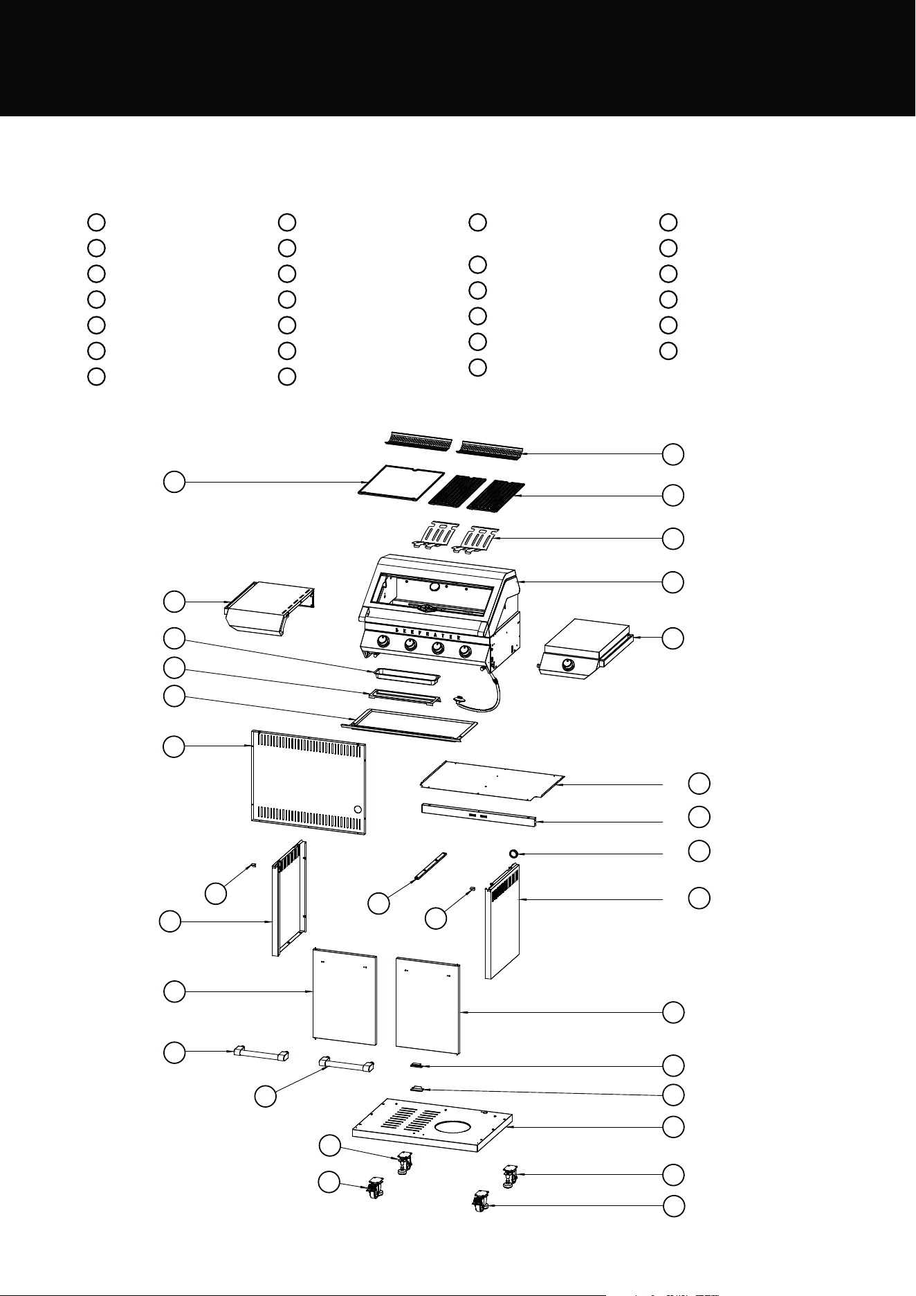
4 PRODUCT DESCRIPTION
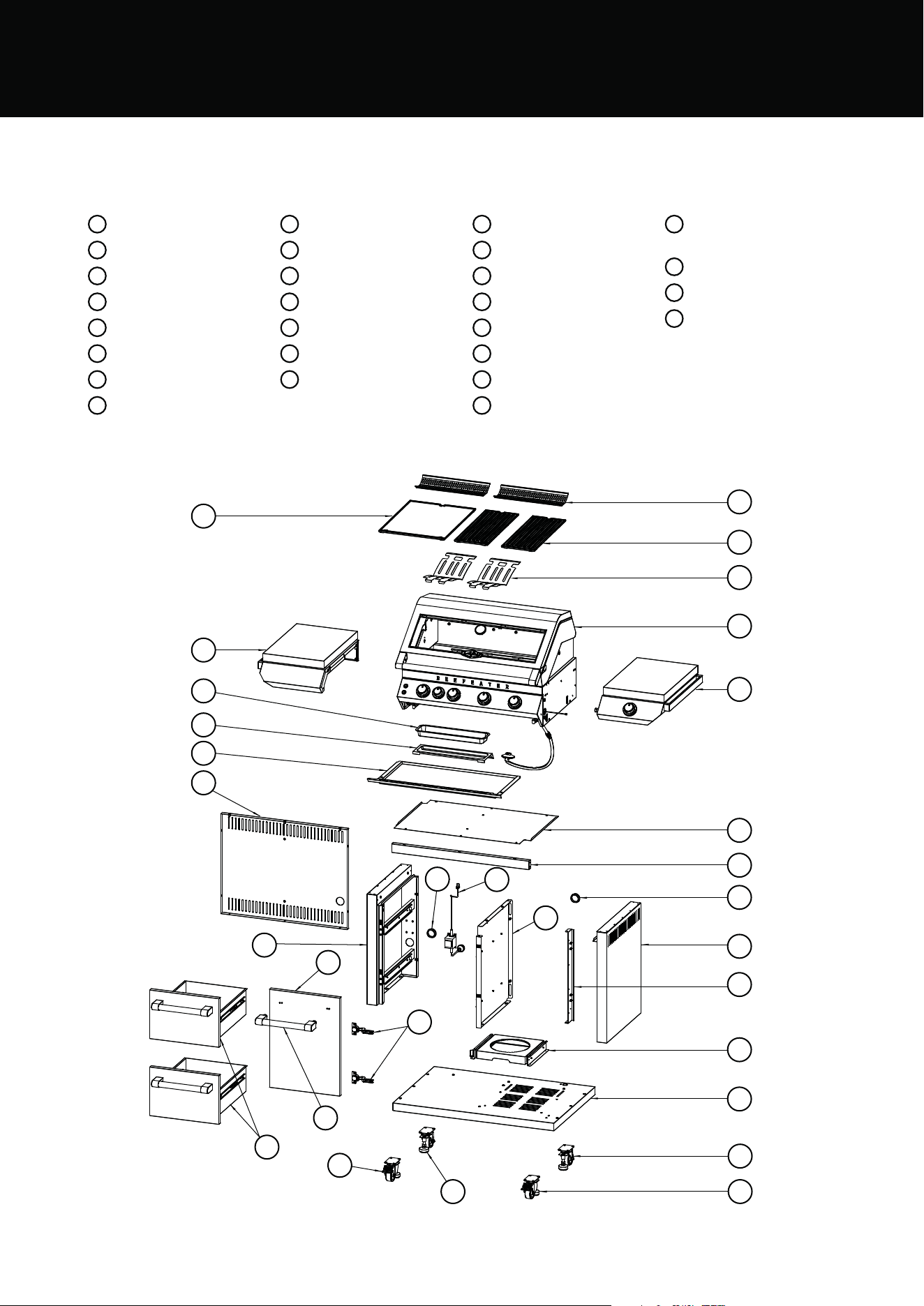
BMF7645SA PRODUCT DESCRIPTION
1
Warming rack x2
2
Cooking grill x2
3
Cooking plate x1
4
Flame tamer x2
5
Body assy x1
6
Left side shelf x1
7
Side burner assy x1
8
Oil foil box x1
9
Foil box holder x1
10
Drip tray x 1
11
Trolley back panel x1
12
Trolley top panel x1
13
Trolley frame coross x1
14
Rubber cover x2
15
Trolley right panel assy
x1
16
Right reinforcing plate x1
17
Trolley mid panel assy x1
18
Transformer x1
19
Trolley left panel assy x1
20
Front door assy x1
21
Door hinge x2
22
Door handle assy x1
23
Drawers assy x2
24
Gas cylinder holder
slider assy x1
25
Trolley bottom panel x1
26
Castors x2
27
Castor with lock x2
3
6
1
2
4
5
7
12
13
14
15
16
24
25
26
27
8
9
10
11
19
20
21
14
17
18
27
22
23
26
BMF7645SA
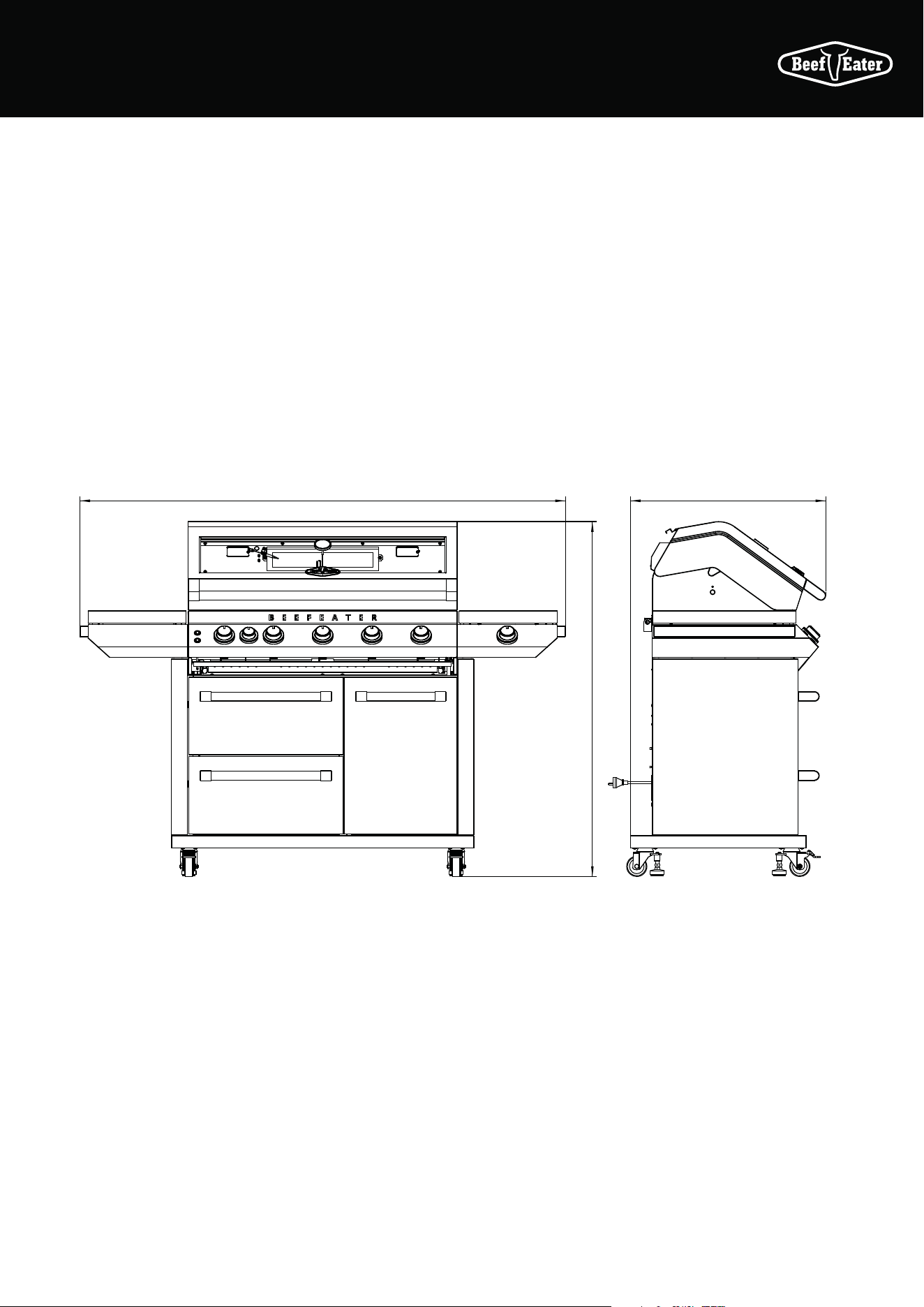
5
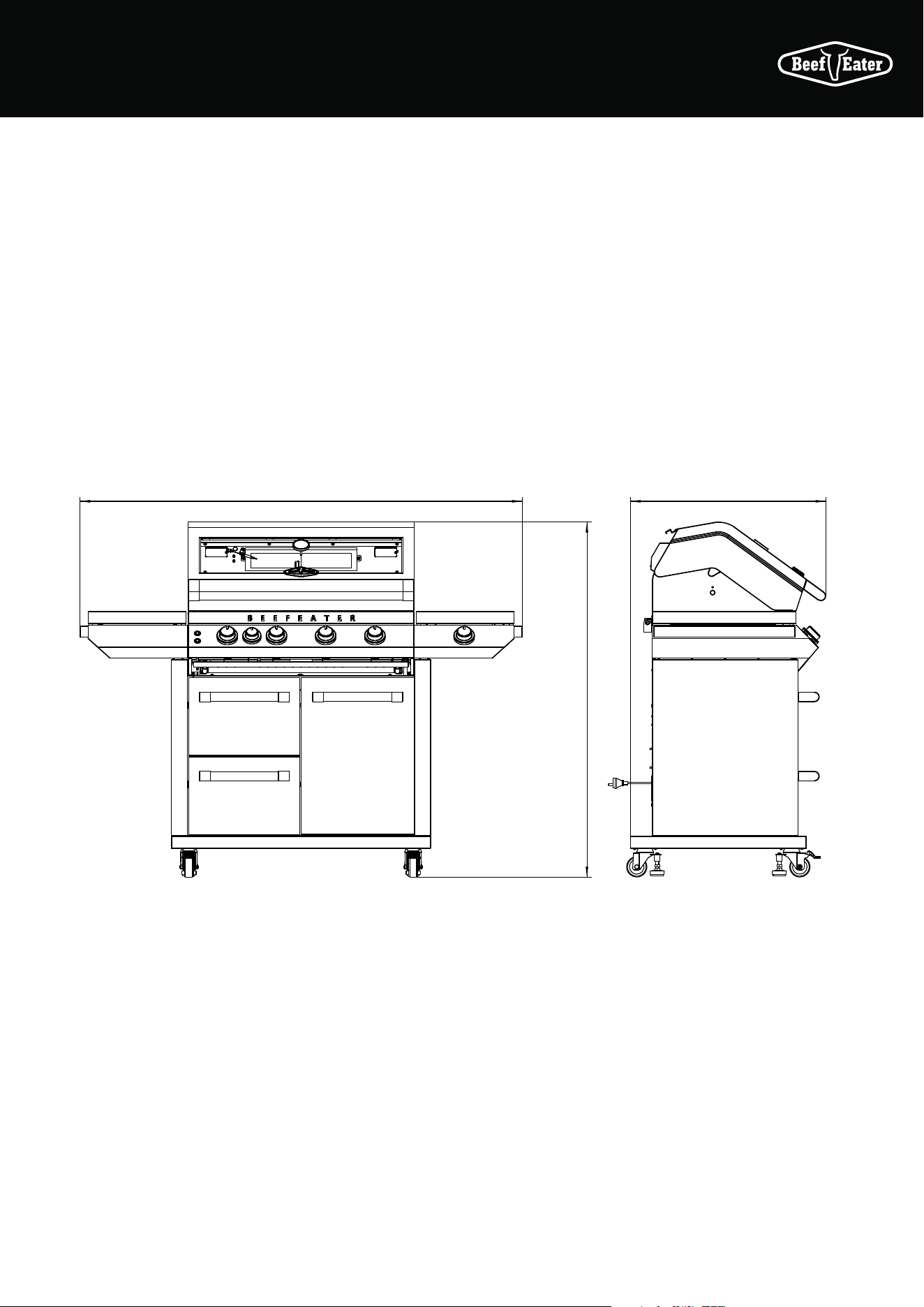
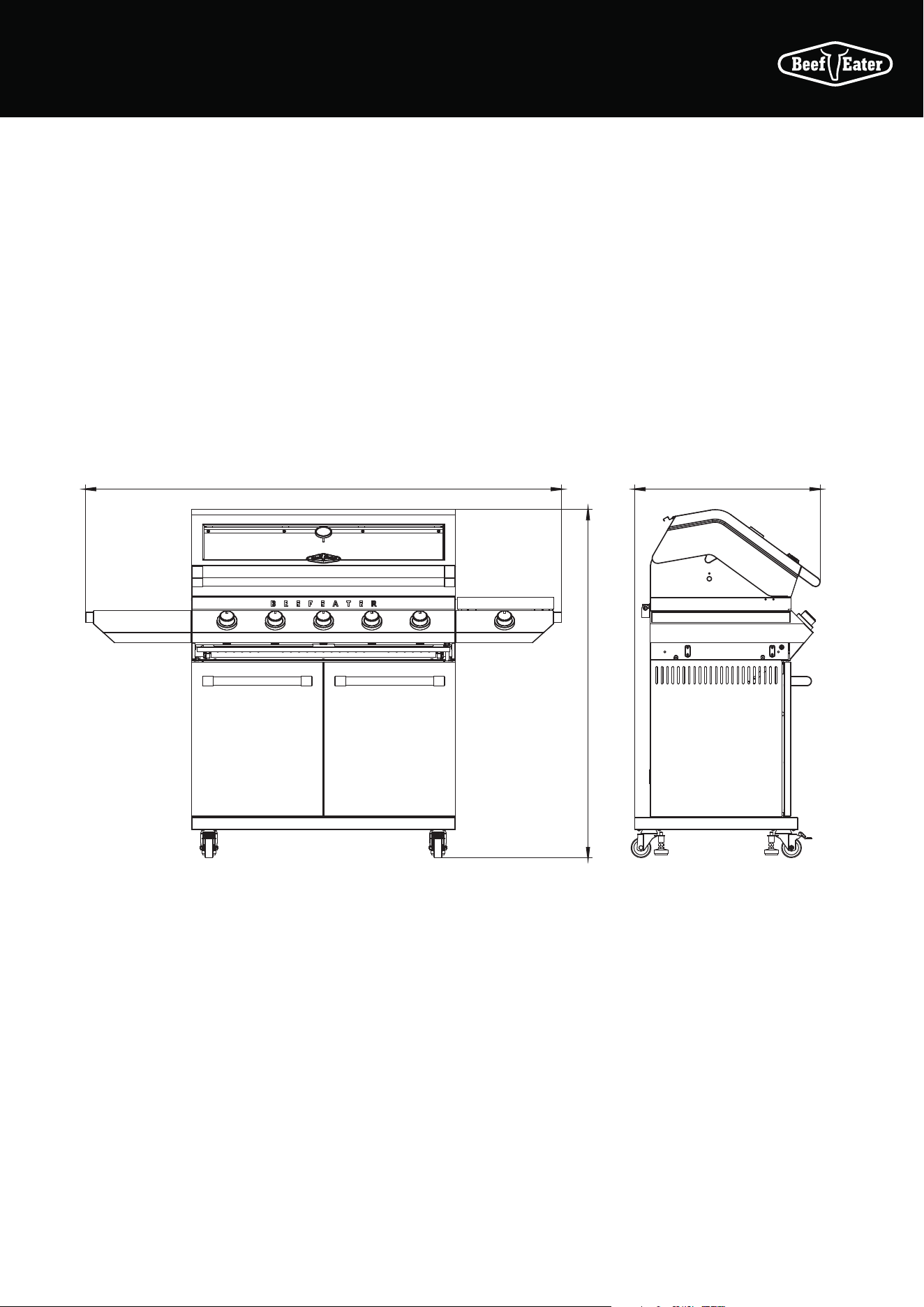
BMF7645SA PRODUCT DIMENSIONS
DIMENSIONS
1602 708
1284
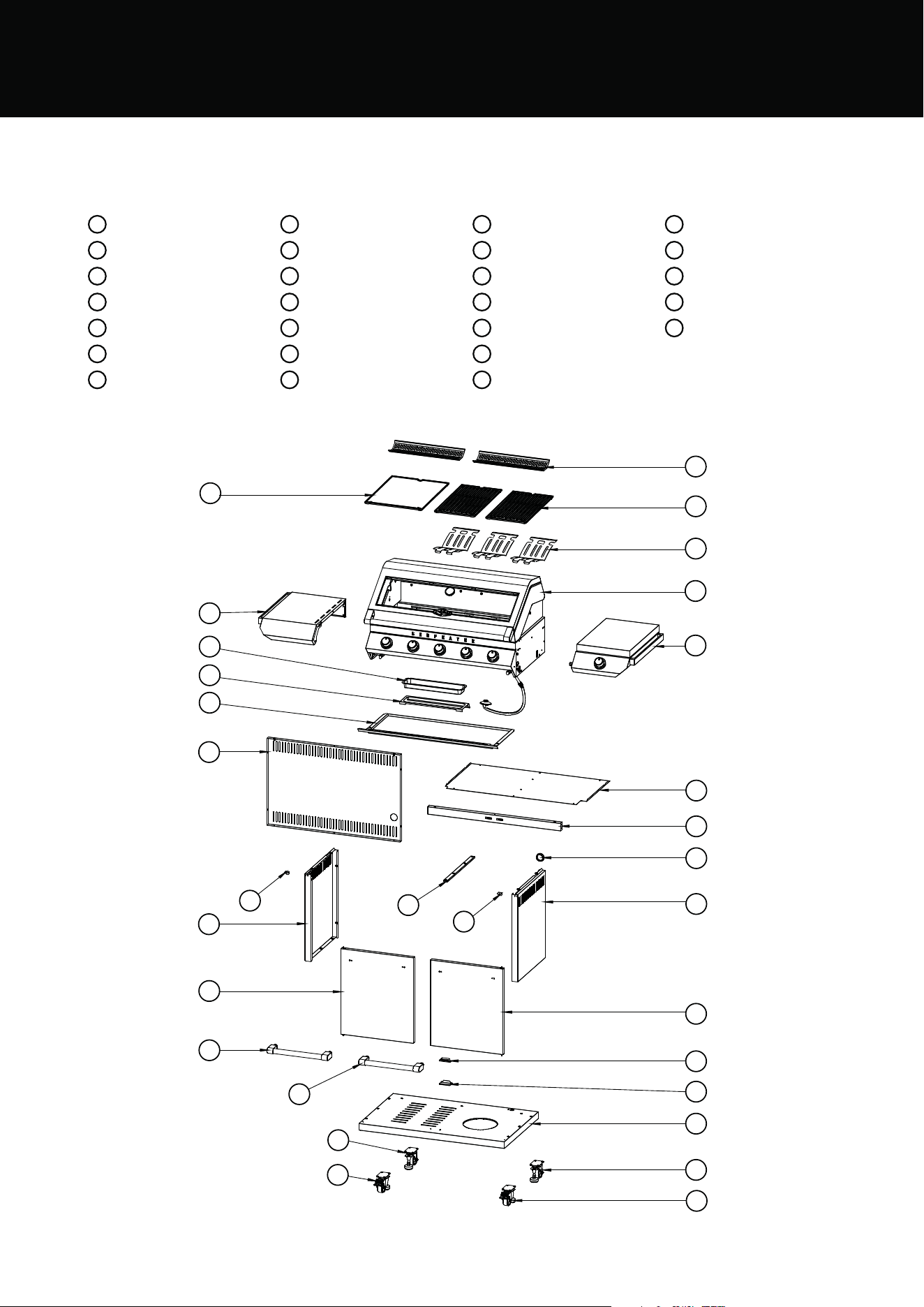
6 PRODUCT DESCRIPTION
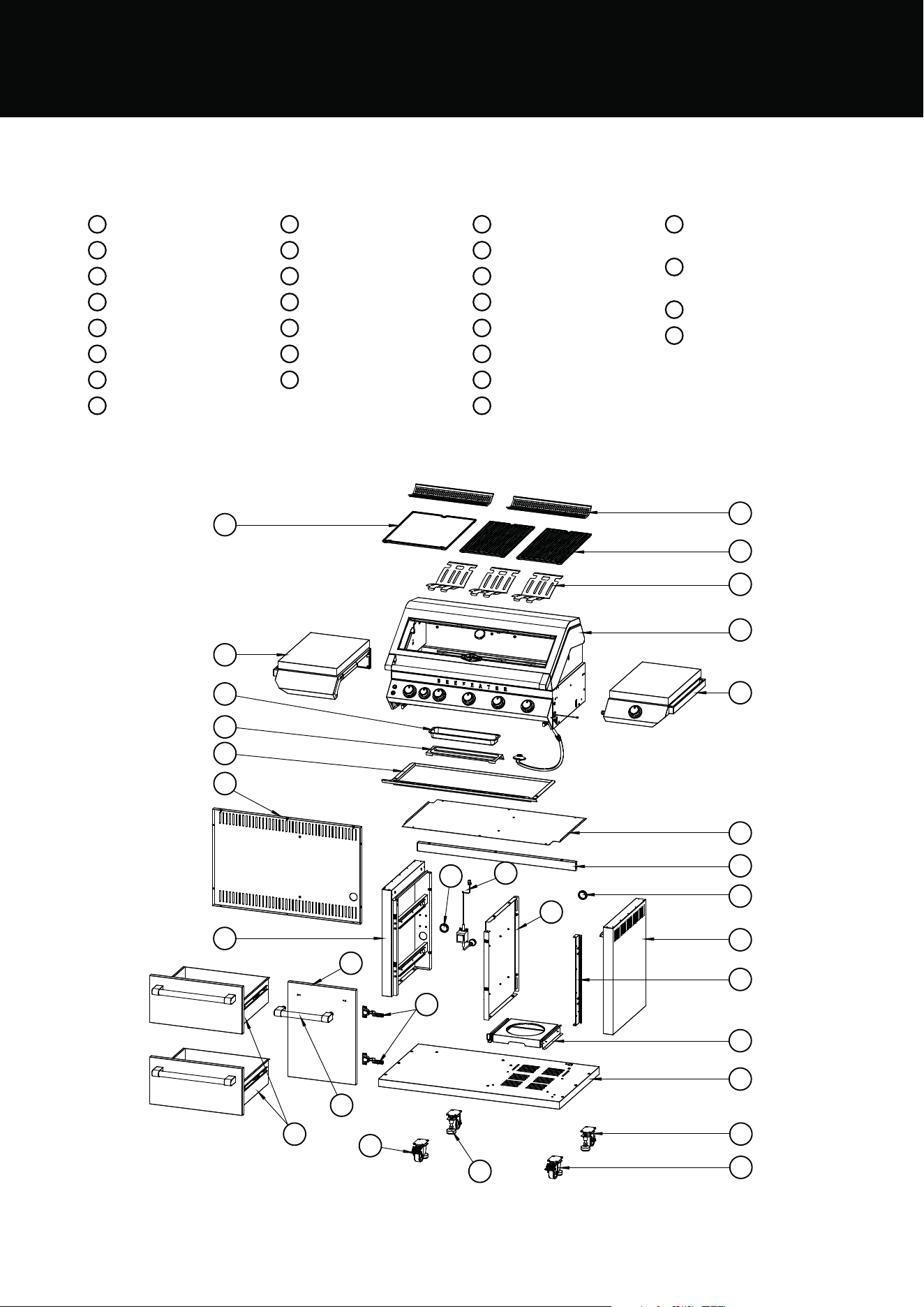
BMF7655SA PRODUCT DESCRIPTION
1
Warming rack x 2
2
Cooking grill x2
3
Cooking plate x1
4
Flame tamer x 3
5
Body assy x1
6
Left shelf x1
7
Right side table x1
8
Oil foil box x 1
9
Foil box holder x 1
10
Drip tray x1
11
Trolley back panel x1
12
Trolley top panel x1
13
Trolley frame cross x 1
14
Rubber cover x2
15
Trolley right panel assy
x1
16
Right reinforcing plate x1
17
Trolley mid panel assy x1
18
Transformer x1
19
Trolley left panel assy x1
20
Door assy x1
21
Door Hinge x2
22
Door handle assy x1
23
Drawer assy x 2
24
Gas cylinder hold slider
assy x 1
25
Trolley bottom panel
assy x1
26
Casters x2
27
Castors with lock x2
3
6
1
2
4
5
7
12
13
14
15
16
24
25
26
27
8
9
10
11
19
20
21
14
17
18
27
22
23
26
BMF7655SA
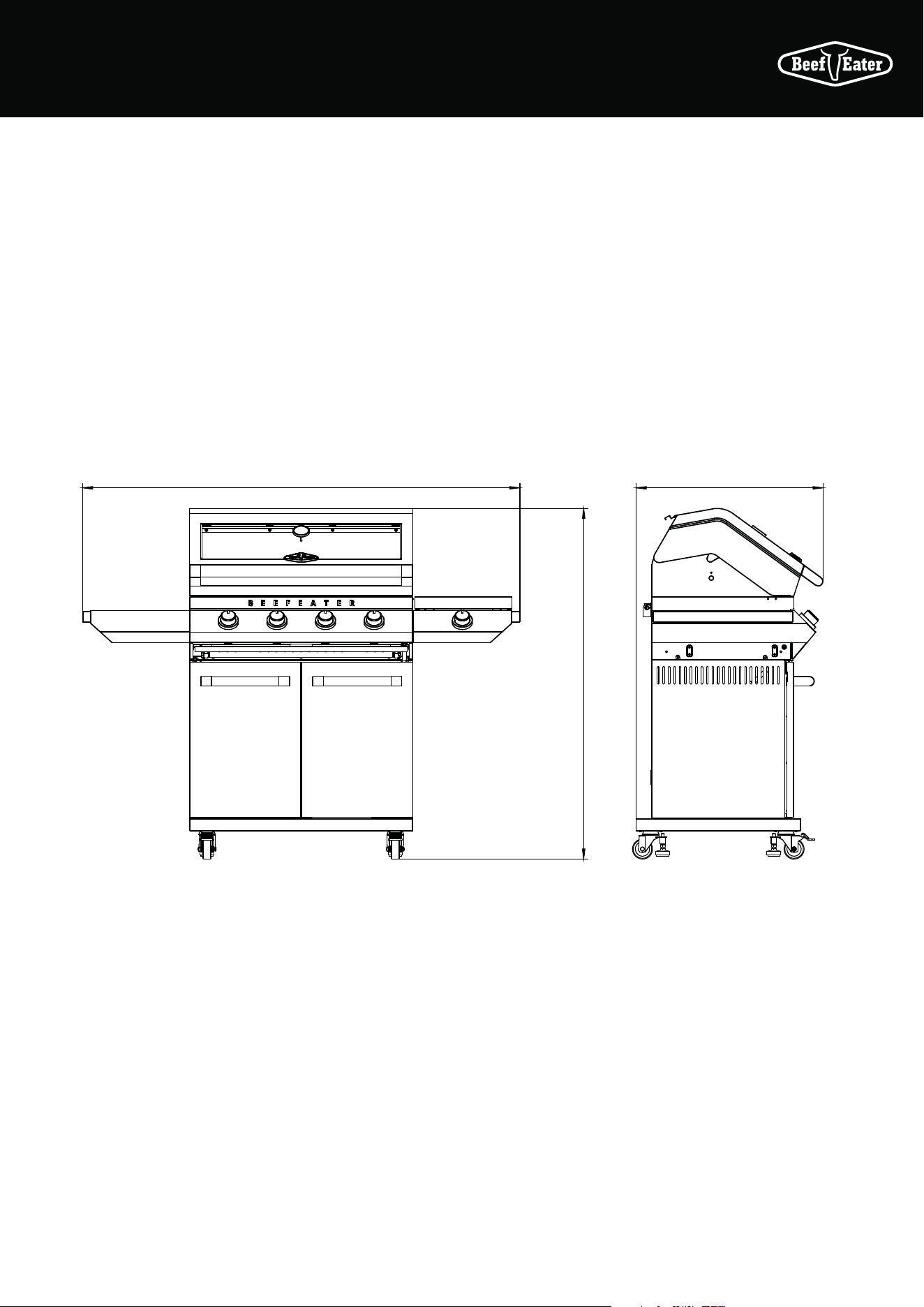
7
BMF7655SA PRODUCT DIMENSIONS
DIMENSIONS
1758 708
1284
8 PRODUCT DESCRIPTION
BMG7642SA PRODUCT DESCRIPTION
1
Warming rack x2
2
Cooking grill x2
3
Cooking plate x1
4
Flame tamer x2
5
Body assy x1
6
Left side shelf x1
7
Side burner assy x1
8
Oil foil box x1
9
Foil box holder x1
10
Drip tray x1
11
Trolley back panel x1
12
Trolley top panel x1
13
Trolley frame coross x1
14
Rubber cover x2
15
Trolley right panel
assy x1
16
Door fixing stator x1
17
Trolley middle frame x1
18
Trolley left panel assy x1
19
Front left door assy x1
20
Front right door assy x2
21
Door handle assy x2
22
Door magnet x1
23
Door magnet stator x1
24
Trolley bottom panel x1
25
Castors x2
26
Castor with lock x2
BMG7642SA
3
6
1
2
4
5
7
12
13
14
15
24
23
22
20
25
26
8
9
10
11
16
18
19
16
17
21
21
26
25
9
BMG7642SA PRODUCT DIMENSIONS
DIMENSIONS
1602 685
1284
10 PRODUCT DESCRIPTION
BMG7652SA PRODUCT DESCRIPTION
1
Warming rack x2
2
Cooking grill x2
3
Cooking plate x1
4
Flame tamer x2
5
Body assy x1
6
Left side shelf x1
7
Side burner assy x1
8
Oil foil box x1
9
Foil box holder x1
10
Drip tray x1
11
Trolley back panel x1
12
Trolley top panel x1
13
Trolley frame coross x1
14
Rubber cover x2
15
Trolley right panel assy x1
16
Door fixing stator x1
17
Trolley middle frame x1
18
Trolley left panel assy x1
19
Front left door assy x1
20
Front right door assy x2
21
Door handle assy x2
22
Door magnet x1
23
Door magnet stator x1
24
Trolley bottom panel x1
25
Castors x2
26
Castor with lock x2
BMG7652SA
3
6
1
2
4
5
7
12
13
14
15
24
23
22
20
25
26
8
9
10
11
16
18
19
16
17
21
21
26
25
11
BMG7652SA PRODUCT DIMENSIONS
DIMENSIONS
1758
685
1284
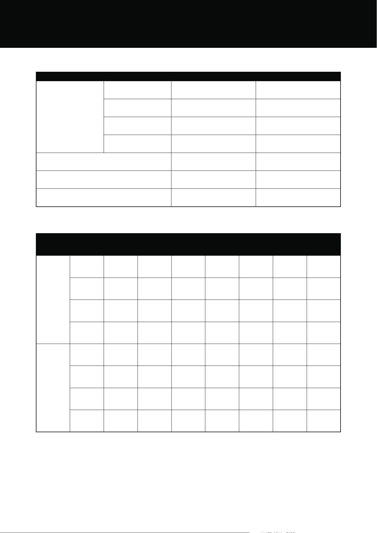
12 GAS SPECIFICATIONS
GAS SPECIFICATIONS
Natural Gas Universal LPG
Injector
orifice diameter -
barbecue burner
BMG7642SA 1.85 1.10
BMG7652SA 1.85 1.10
BMF7645SA 2.05 1.11
BMF7655SA 2.05 1.11
Injector diameter-side burner
BMG7642SA & BMG7652SA
1.87 1.15
Injector diameter-side burner
BMF7645SA & BMF7655SA
2.4 1.35
Injector diameter-rear burner
BMF7645SA & BMF7655SA
1.55 0.94
GAS TYPE
Gas type
Model Name
Main Burner
Qty
Rating
MJ/h
Rear Burner
Qty
Rating
MJ/h
Side Burner
Qty
Rating
MJ/h
Total Rating
MJ/h
NG
BMG7642SA 4 68 0 0 1 17 85
BMG7652SA 5 85 0 0 1 17 105
BMF7645SA 4 68 1 11 1 21 100
BMF7655SA 5 85 1 11 1 21 117
LPG
BMG7642SA 4 68 0 0 1 17 85
BMG7652SA 5 85 0 0 1 17 105
BMF7645SA 4 68 1 11 1 23 102
BMF7655SA 5 85 1 11 1 23 119
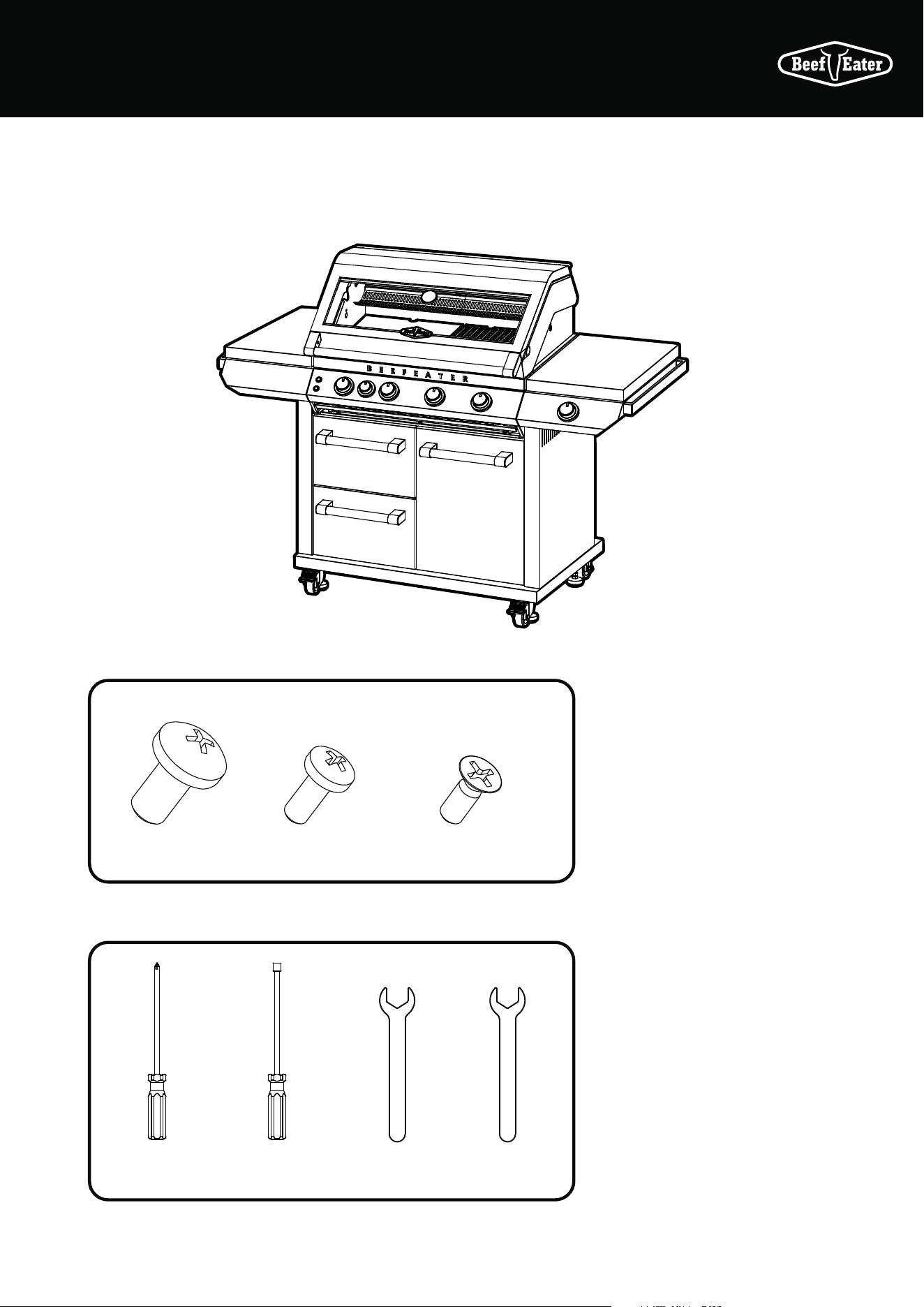
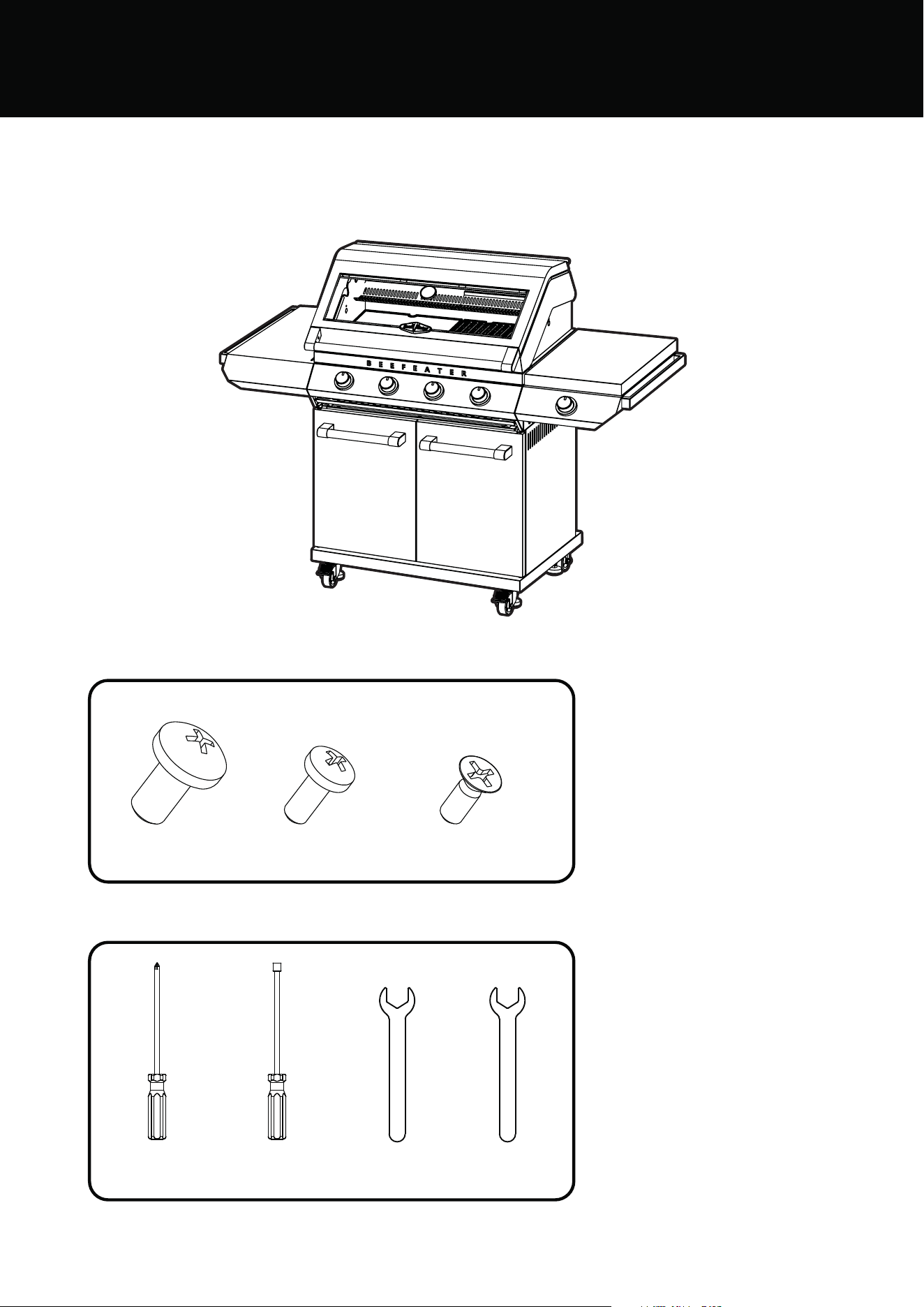
13ASSEMBLING THE BARBECUE
BMF7645SA
BMF7655SA
BMF7645SA & BMF7655SA ASSEMBLY
For BMF7645SA & BMF7655SA
M6 x 12mm
M4 x 10mm
flat head
M4 x 10mm
countersunk head
x4x15x60
Tools required:
Hexagonal
screwdriver
Phillips
screwdriver
Wrench 22mm
Wrench 19mm
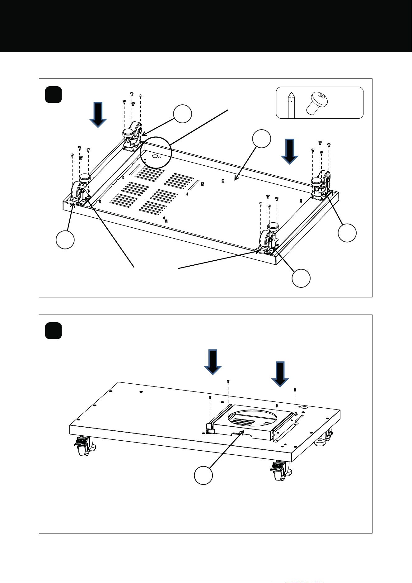
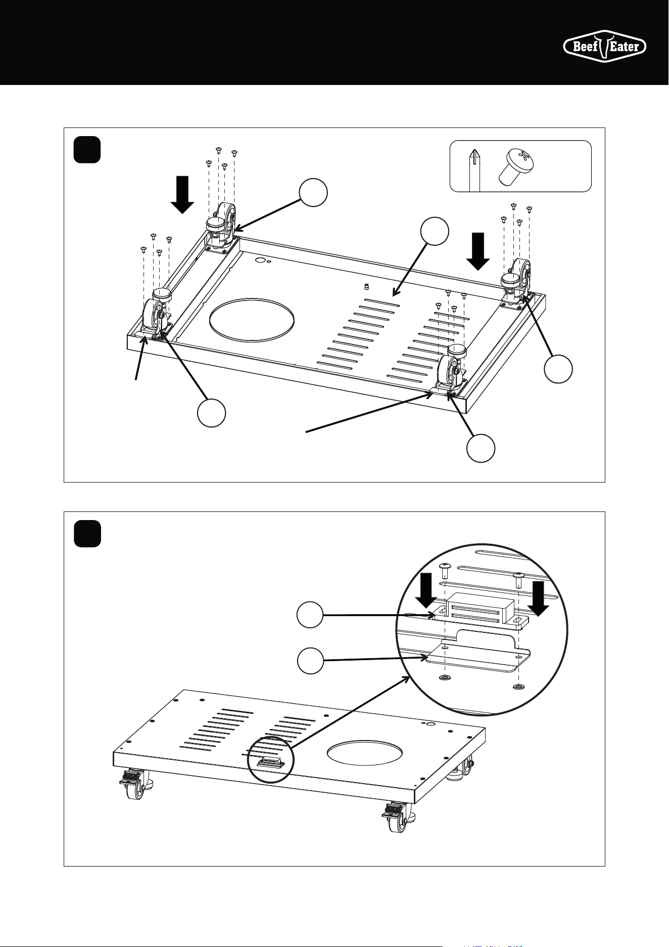
14 ASSEMBLING THE BARBECUE
25
26
26
27
27
24
1
2
Castor with
locks at the
front position
The hole is
at the back
BMF7645SA & BMF7655SA ASSEMBLY
M6 x 12mm
x 16
Attach 4 castors
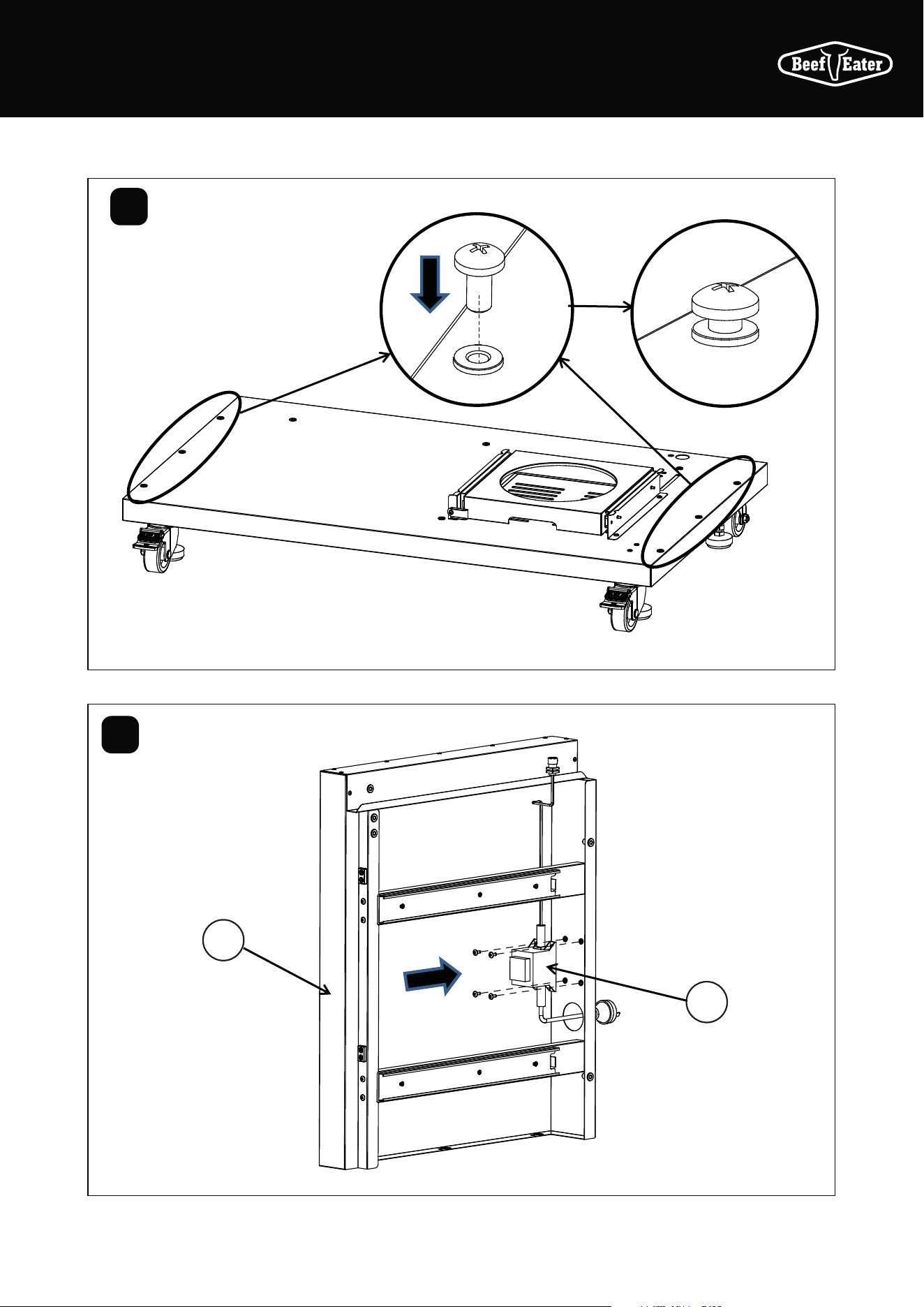
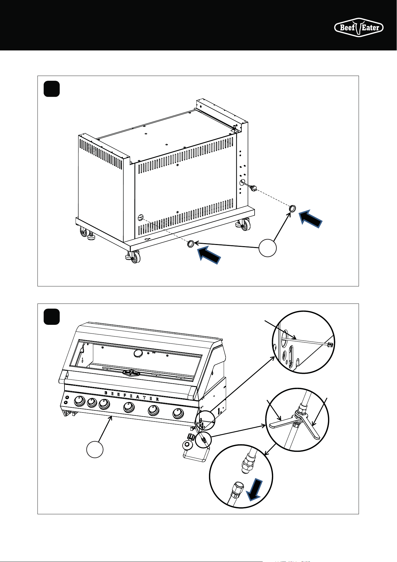
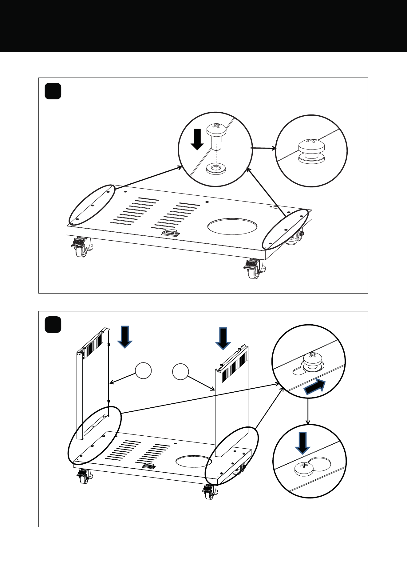
15ASSEMBLING THE BARBECUE
4
18
19
3
16
19
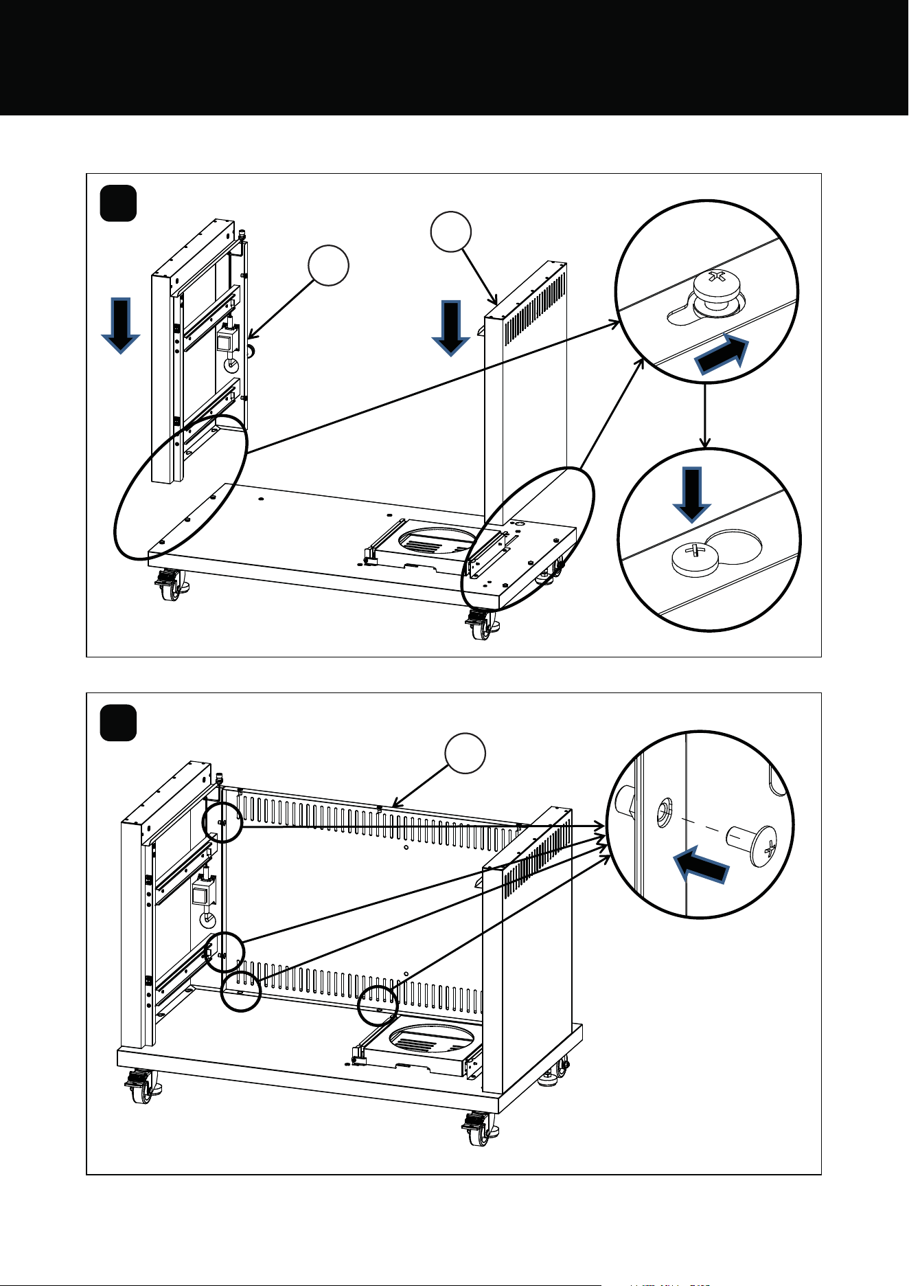
15
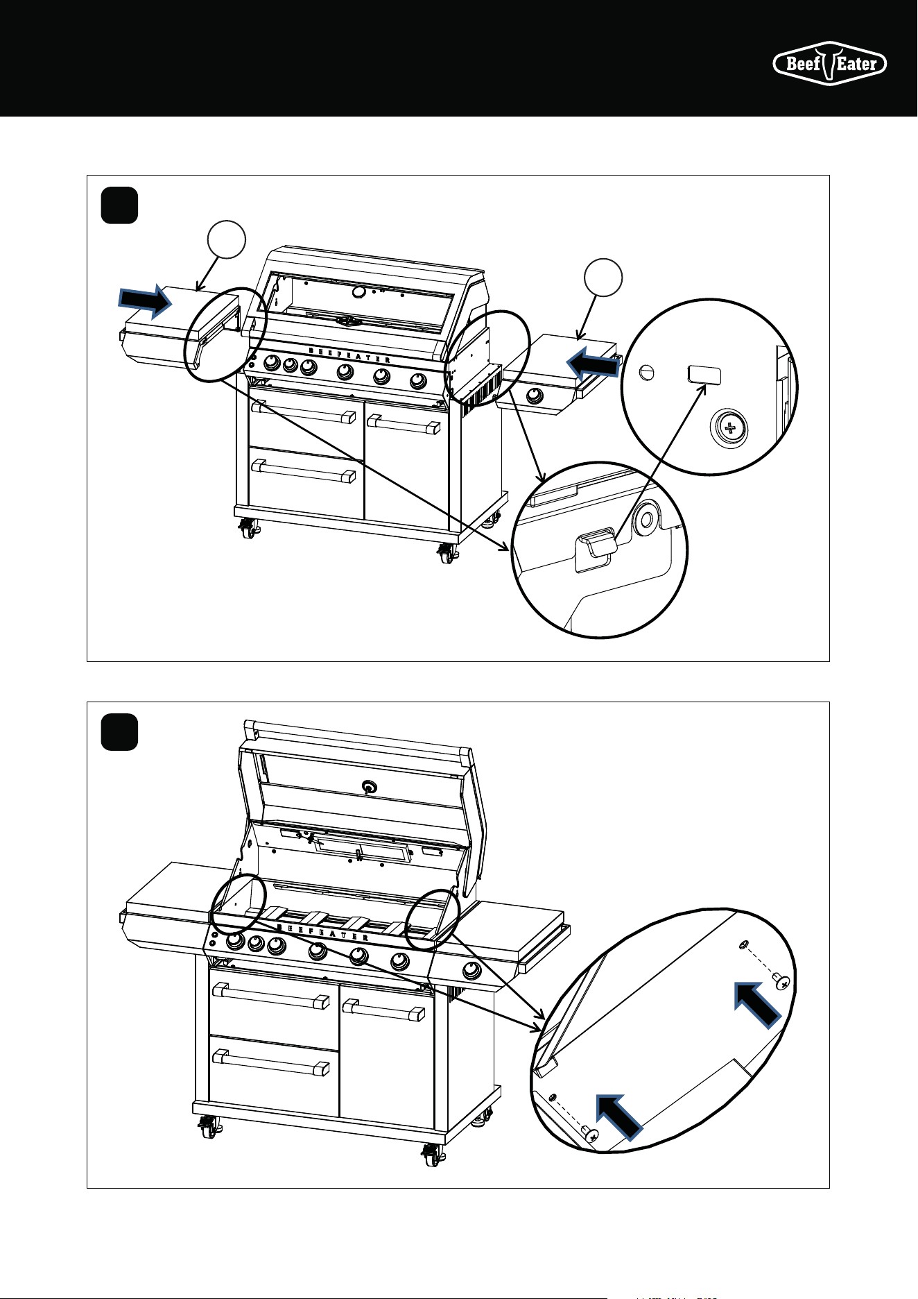
ASSEMBLING THE BARBECUE
5
6
11
BMF7645SA & BMF7655SA ASSEMBLY
17ASSEMBLING THE BARBECUE
7
8
11
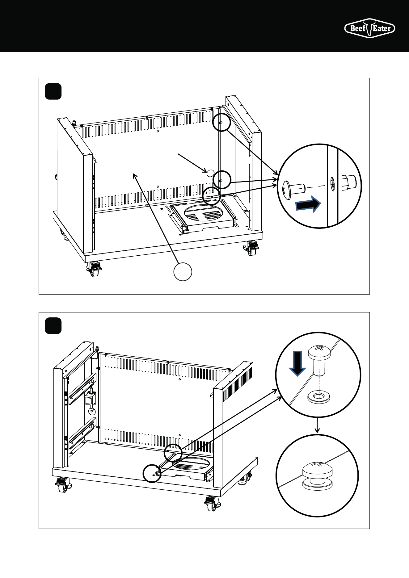
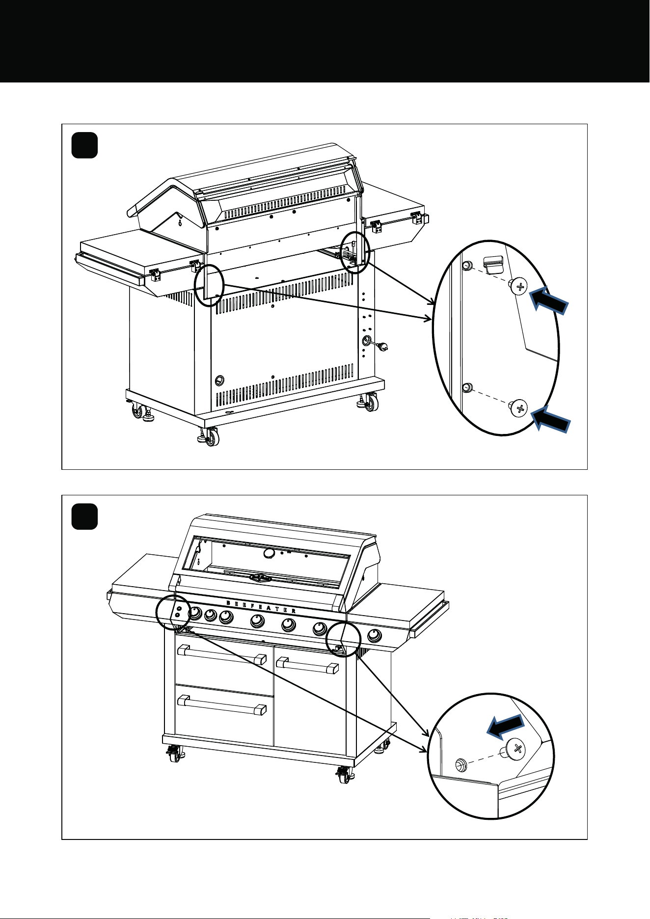
18 ASSEMBLING THE BARBECUE
17
9
10
BMF7645SA & BMF7655SA ASSEMBLY
19ASSEMBLING THE BARBECUE
11
12
13
16
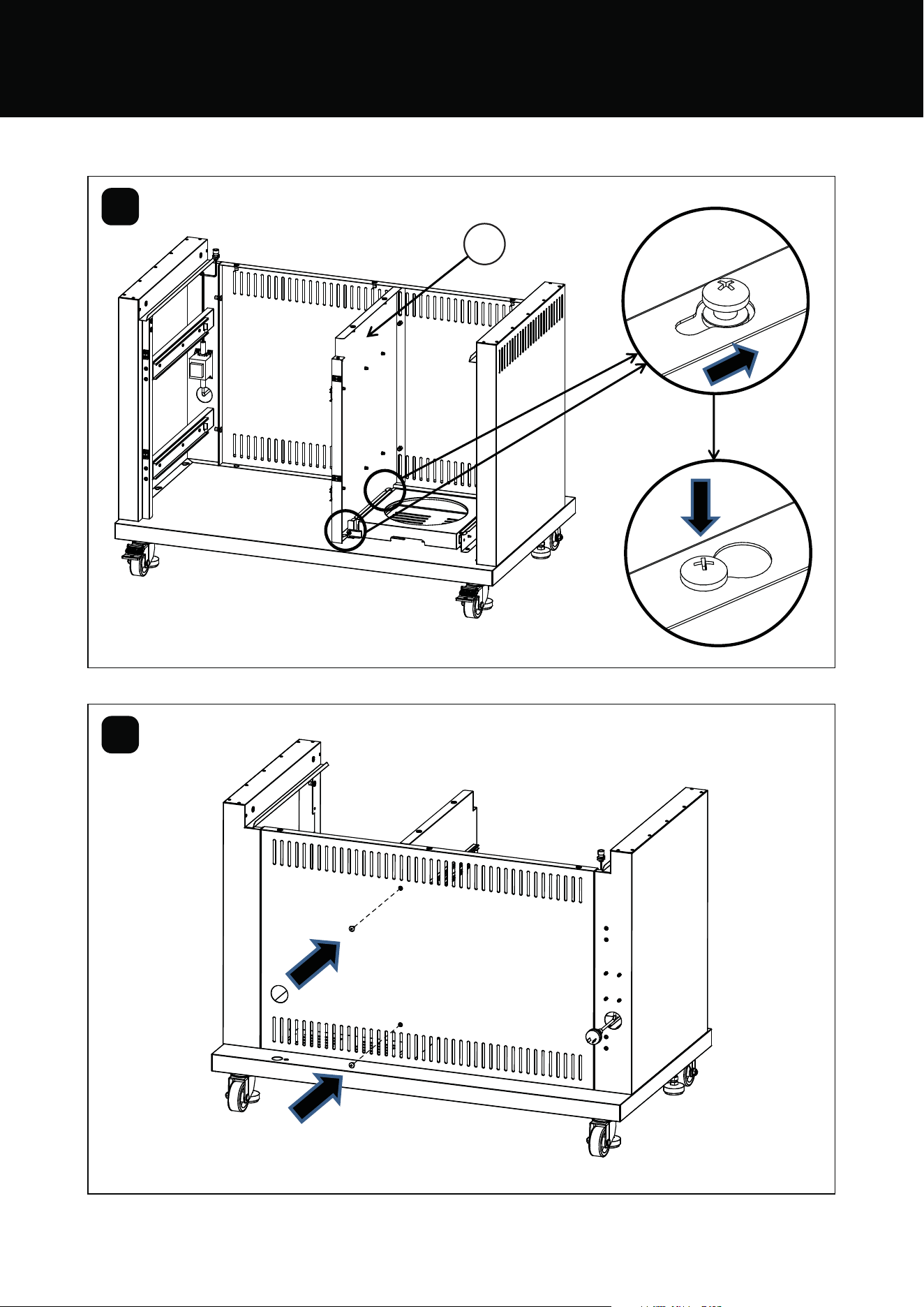
20 ASSEMBLING THE BARBECUE
11
13
14
23
BMF7645SA & BMF7655SA ASSEMBLY
21ASSEMBLING THE BARBECUE
15
16
20
22
21
22 ASSEMBLING THE BARBECUE
17
18
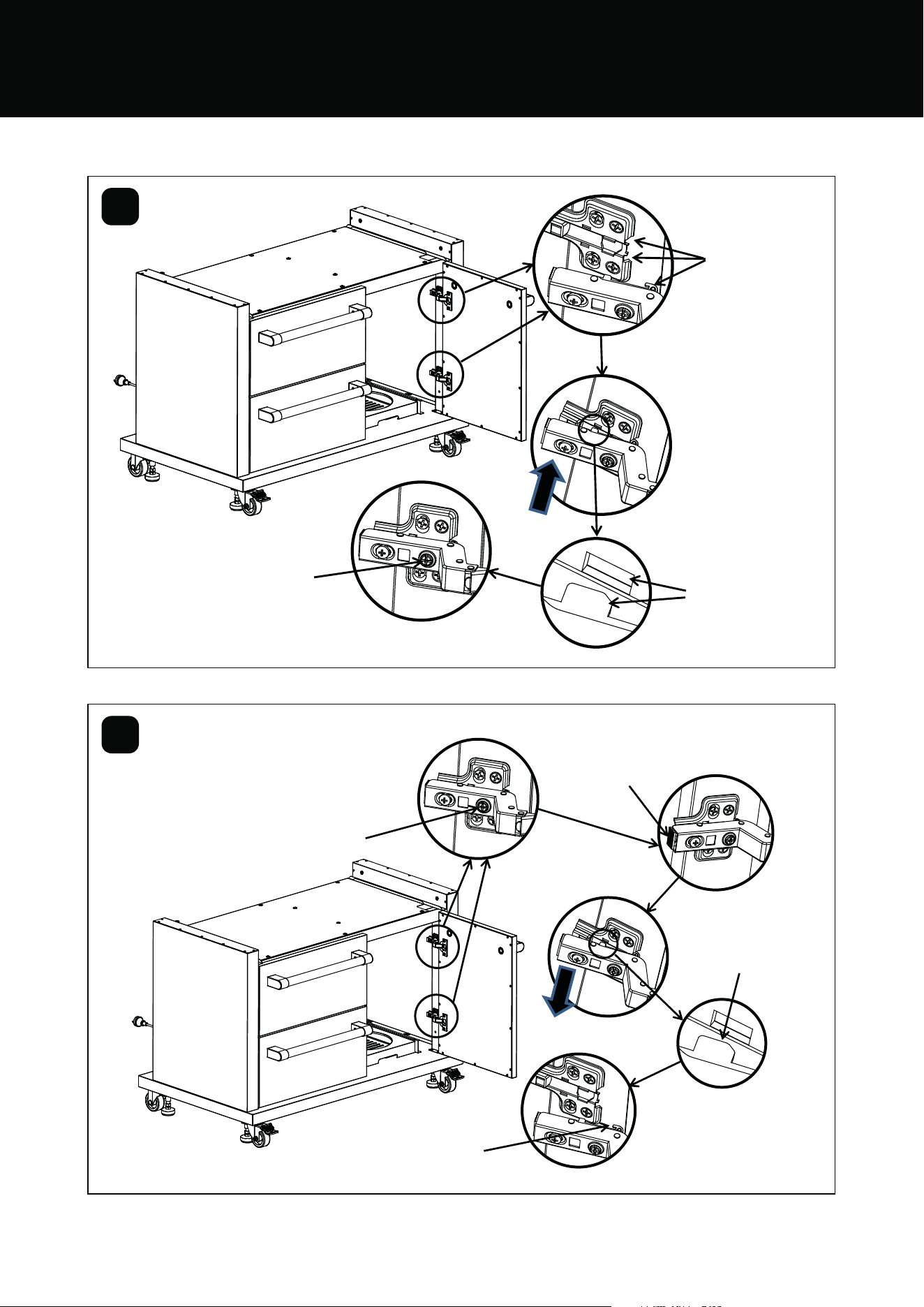
Assemble the front door
Disassemble the front door
When the hinge
installed, turn
this screw in
counterclockwise, to
level the front door
Firstly turn the screw
in clockwise for 1-2
complete turns
Then press the button
Pull the the upper and
lower two tabs out of
the rectangular slot
Finally, pull the
hooks out
When connected,
the upper and lower
two tabs should be
aligned with the
rectangular slot
Then press
down, when
hear “pop”, the
assembly is in
place
Firstly, insert
the upper and
lower hook into
the slots
BMF7645SA & BMF7655SA ASSEMBLY
23ASSEMBLING THE BARBECUE
19
20
14
5
Spanner
19mm
Spanner
19mm
Electrical wires
need to be kept
outside, through
the indicated hole
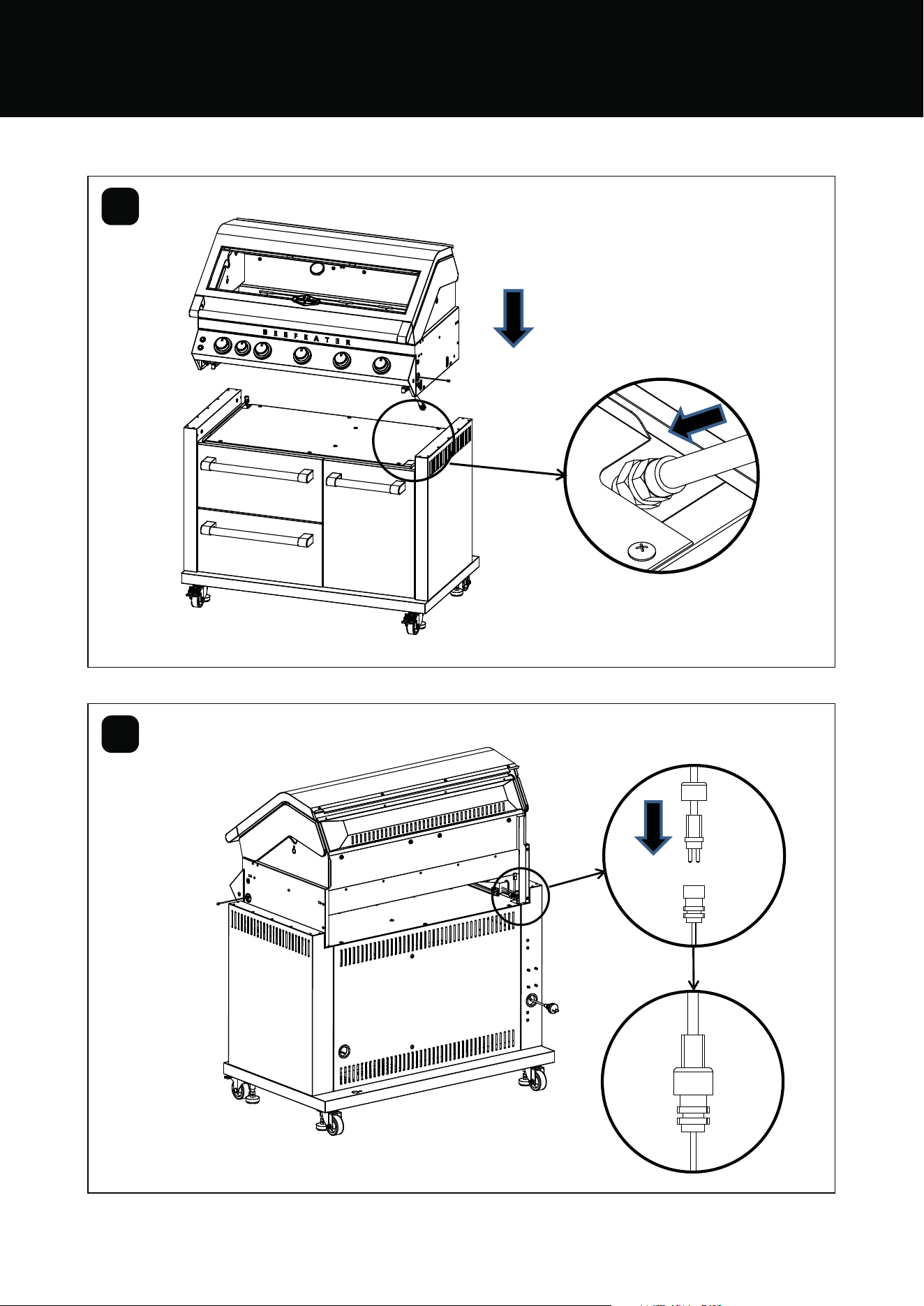
24 ASSEMBLING THE BARBECUE
21
22
Assemble the transformer wires
and the lighting wires, screw the
connection to seal.
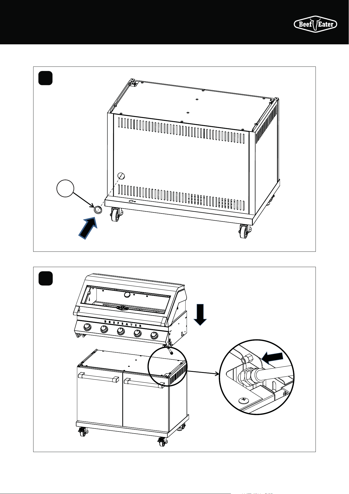
BMF7645SA & BMF7655SA ASSEMBLY
Recommend at least 2 people
to lift. Due to the assembled
body being a heavy lift
Carefully locate the gas pipe into
the hole of the trolley top panel
25ASSEMBLING THE BARBECUE
23
24
Insert the wires into the
trolley to hide the wires
Disassemble the hose to easily
access the screw hole
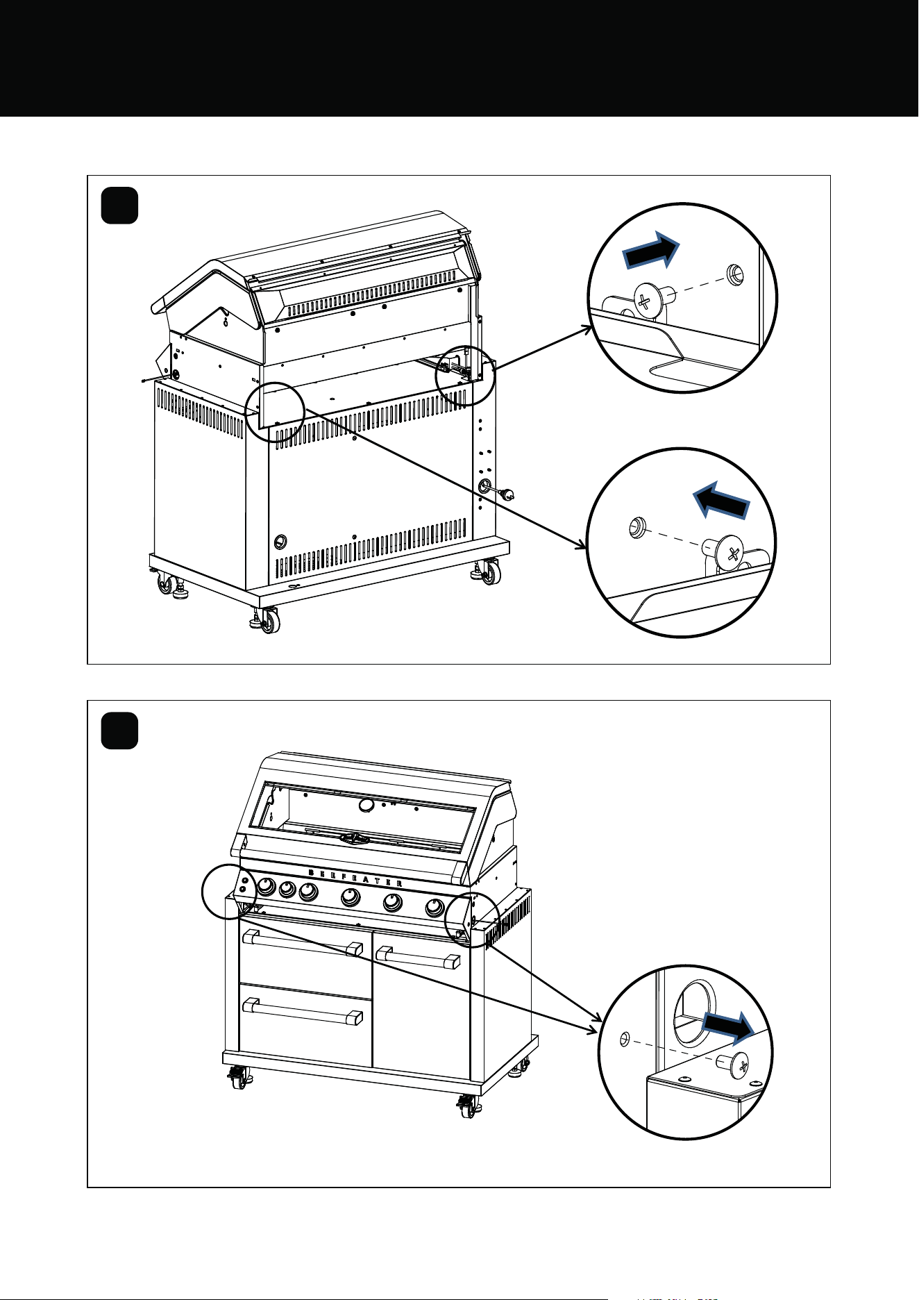
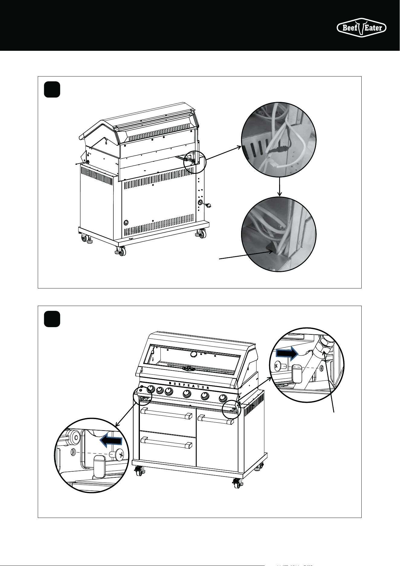
26 ASSEMBLING THE BARBECUE
25
26
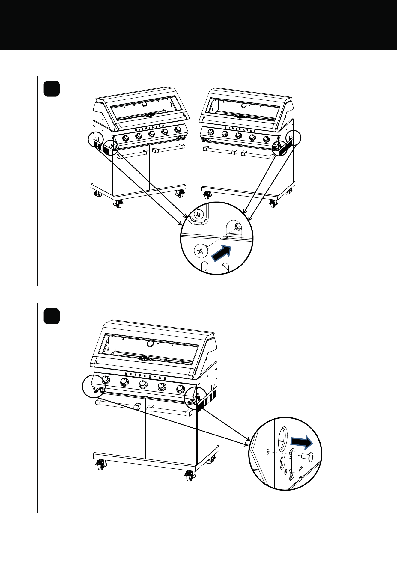
BMF7645SA & BMF7655SA ASSEMBLY
27ASSEMBLING THE BARBECUE
27
28
6
7
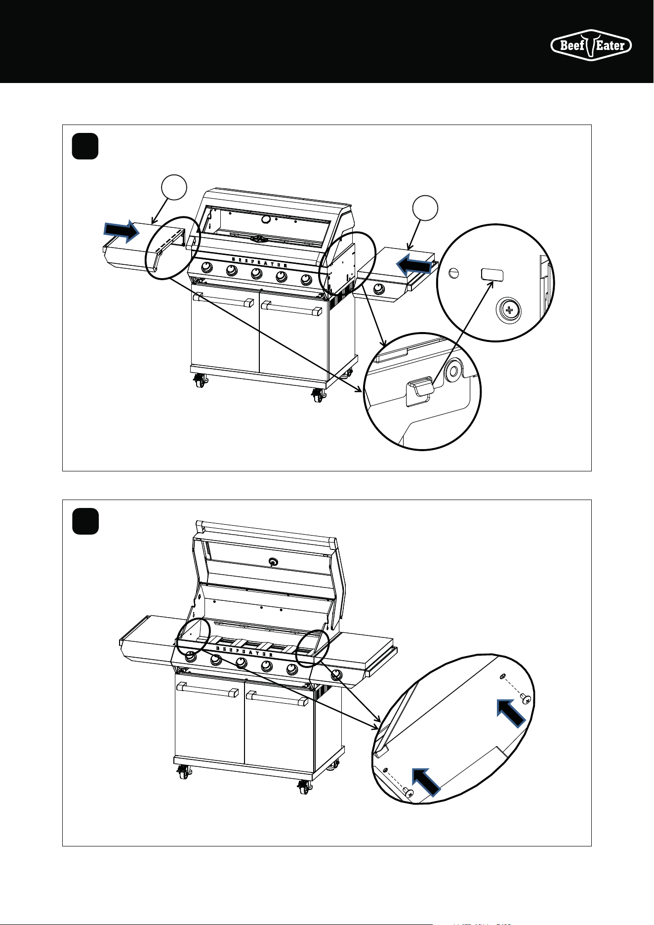
28 ASSEMBLING THE BARBECUE
29
30
BMF7645SA & BMF7655SA ASSEMBLY
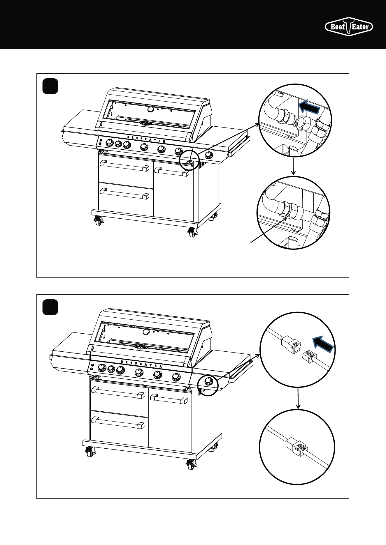
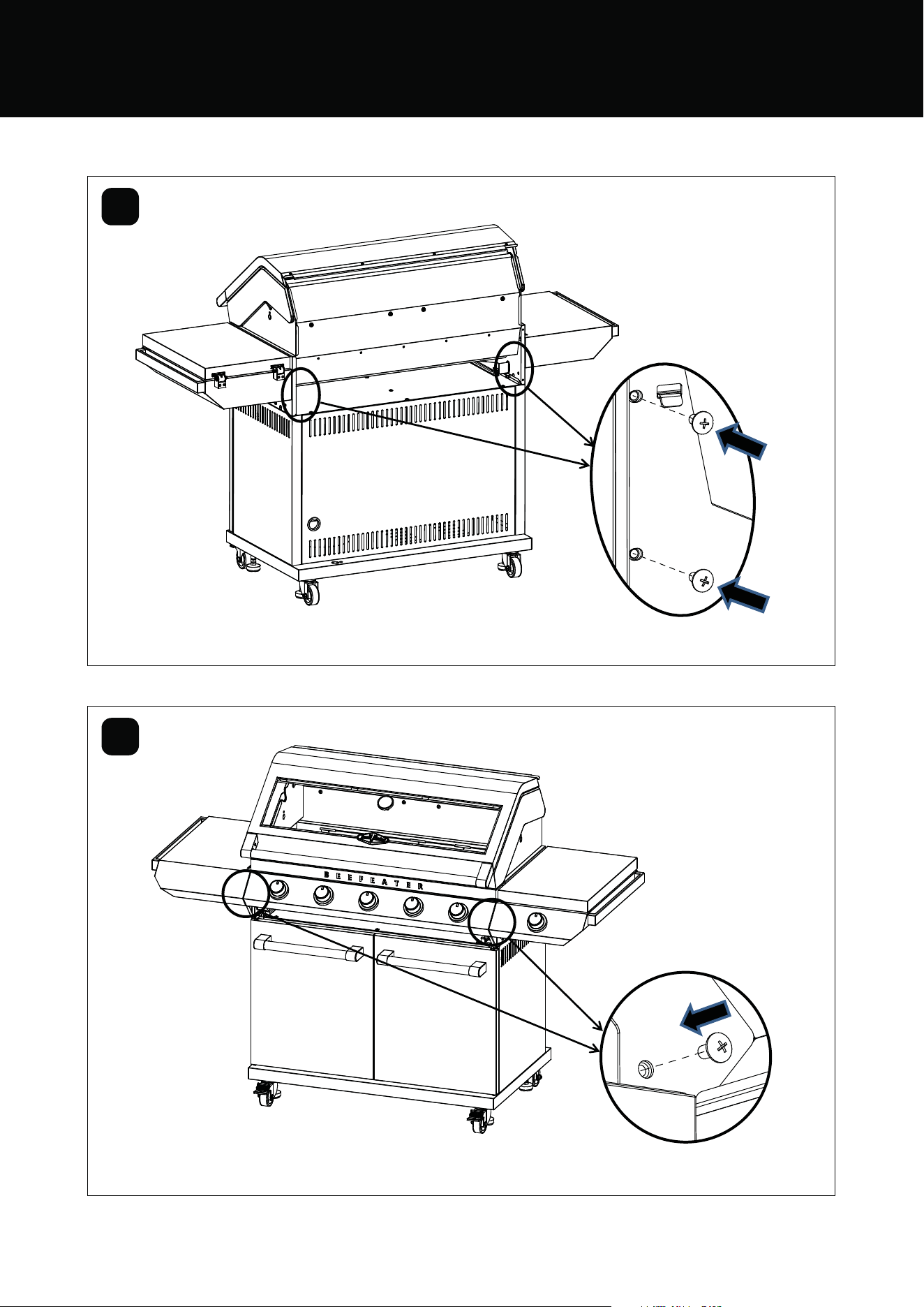
29ASSEMBLING THE BARBECUE
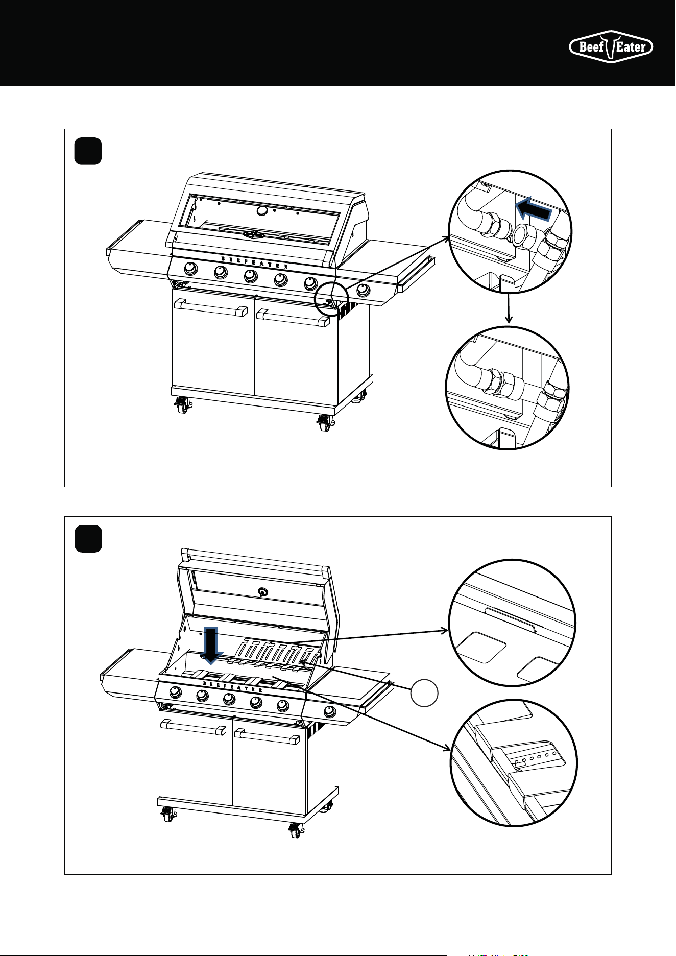
31
32
Assemble side burner gas
pipe to the manifold using
2 spanners
Connect
the wires
underneath
the side
burner
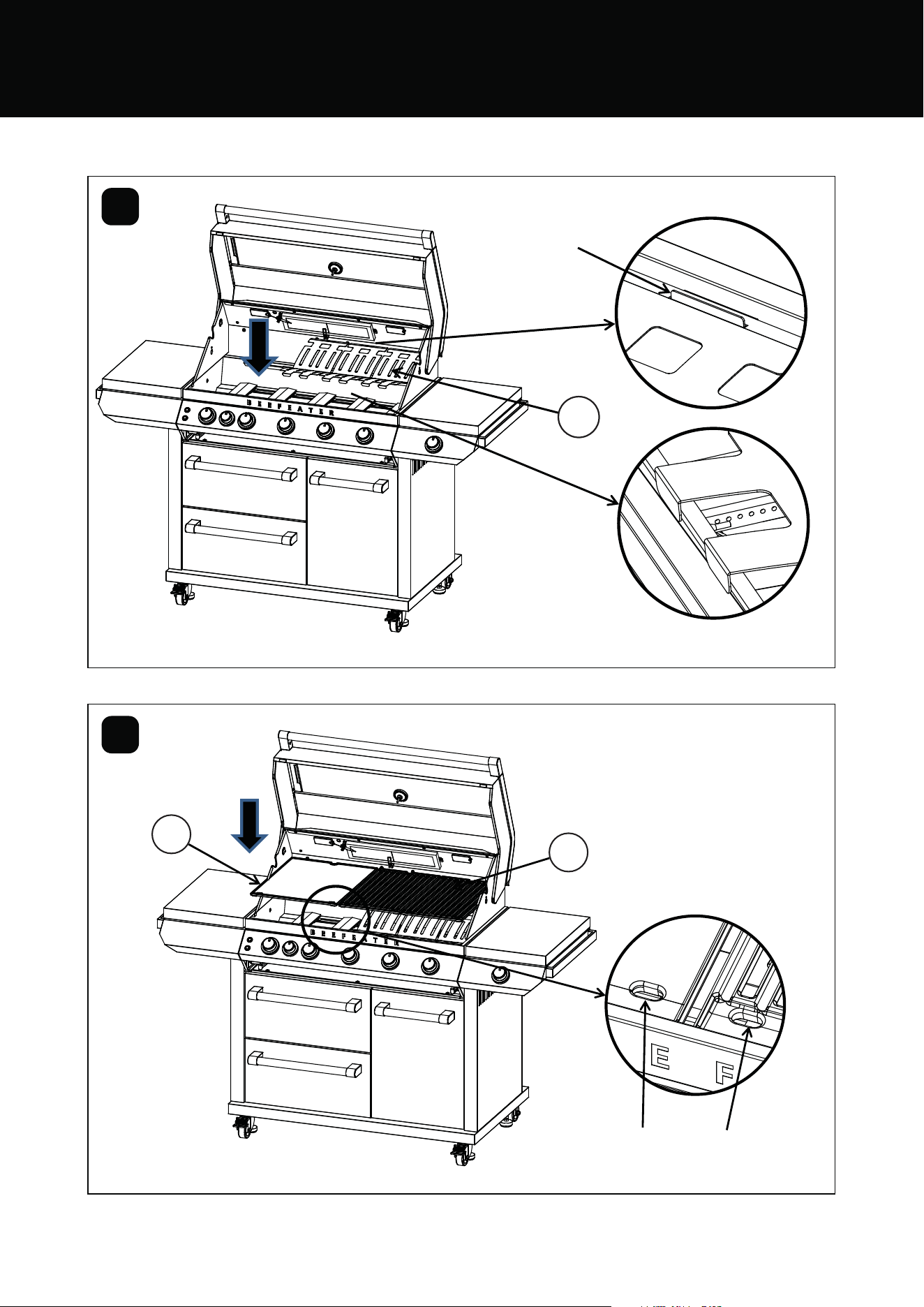
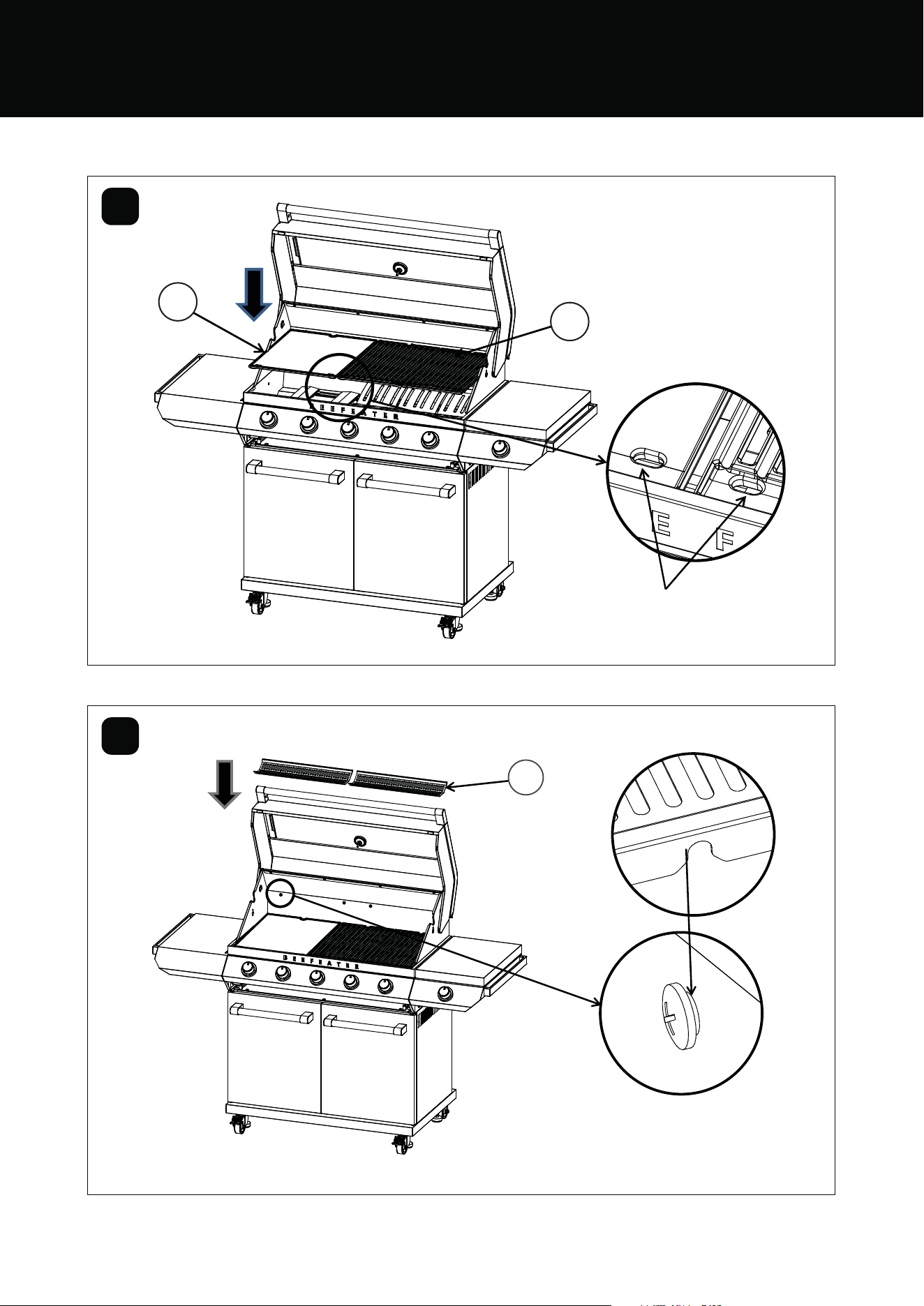
30 ASSEMBLING THE BARBECUE
4
33
34
3
2
Locate the flame
tamers:
2 flame tamers for
4 burners
3 flame tamers for
5 burners
Drainage holes are at the front
BMF7645SA & BMF7655SA ASSEMBLY
31ASSEMBLING THE BARBECUE
35
36
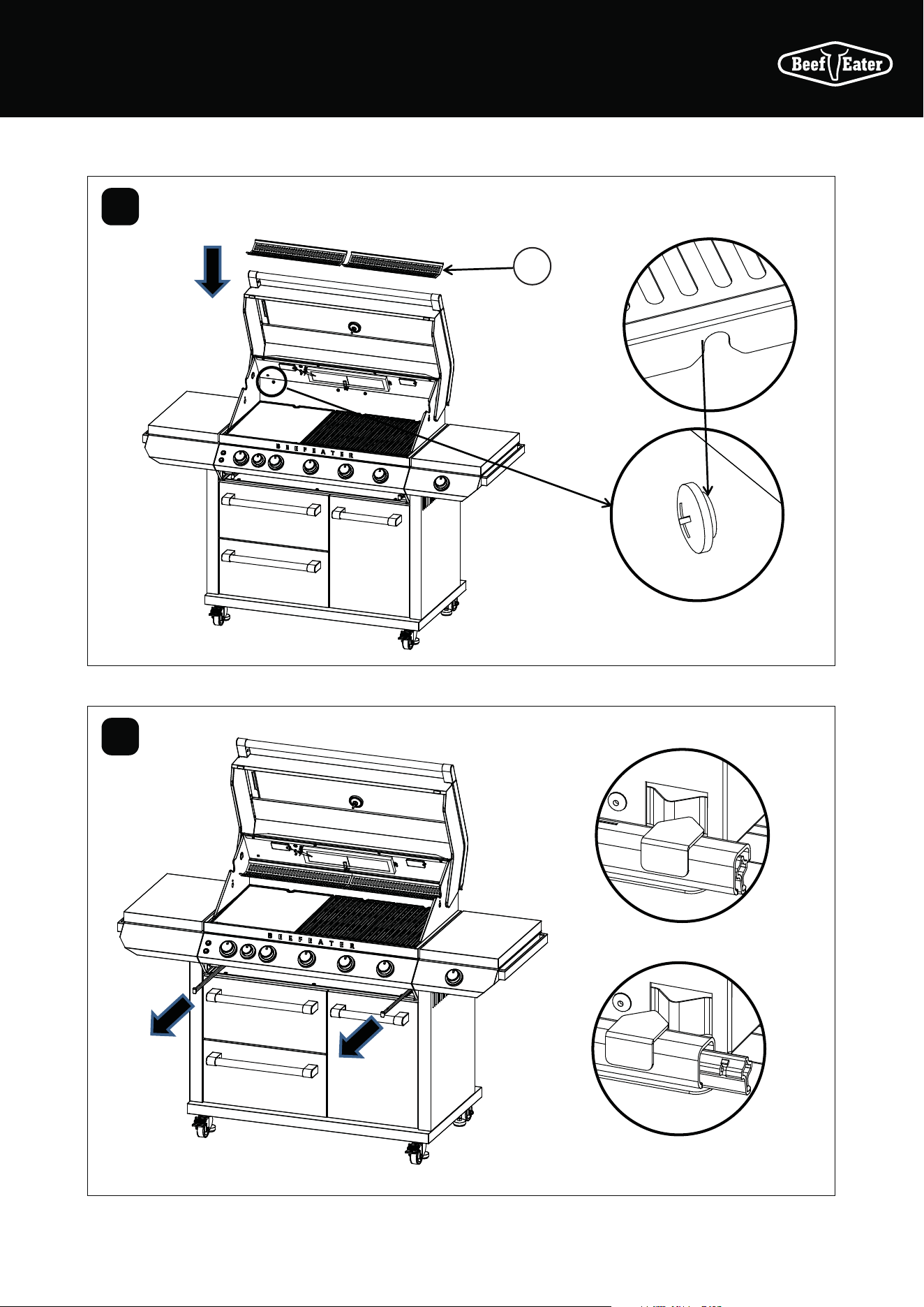
1
Locate the warming rack
Sliding locked
Sliding unlocked
32 ASSEMBLING THE BARBECUE
10
37
38
9
BMF7645SA & BMF7655SA ASSEMBLY
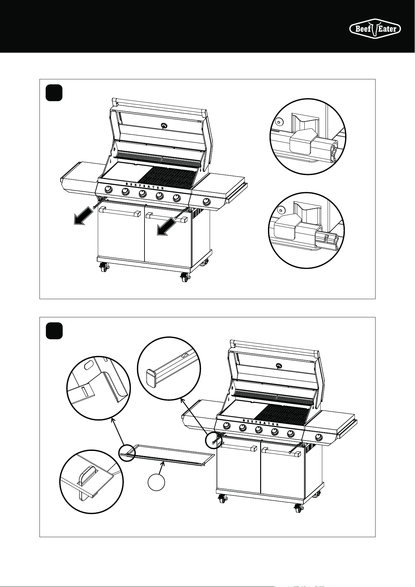
33ASSEMBLING THE BARBECUE
39
40
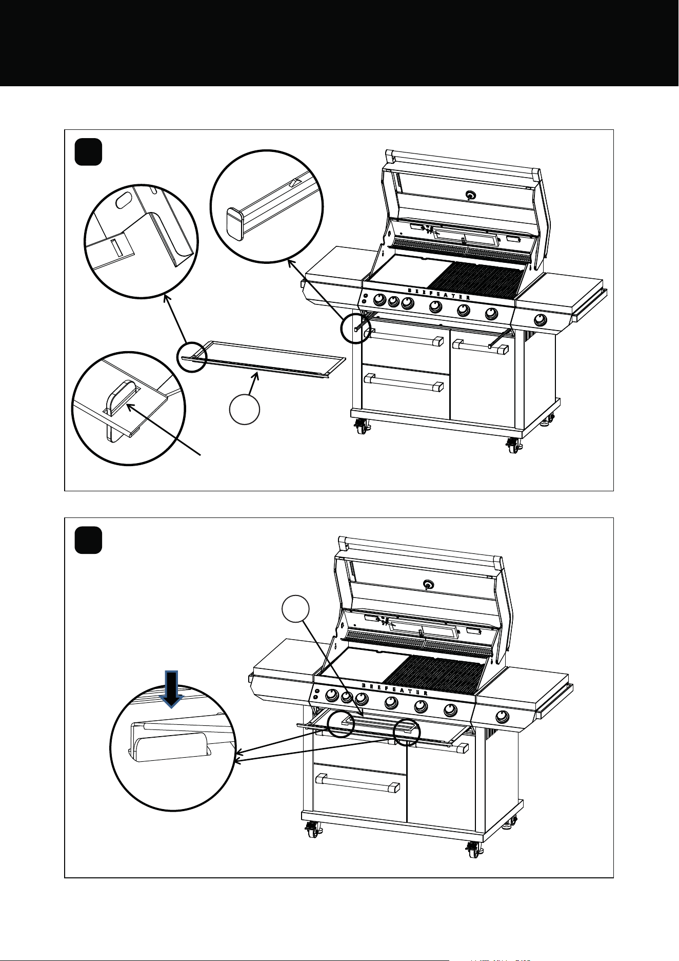
8
Spanner
19mm
Spanner
22mm
34 ASSEMBLING THE BARBECUE
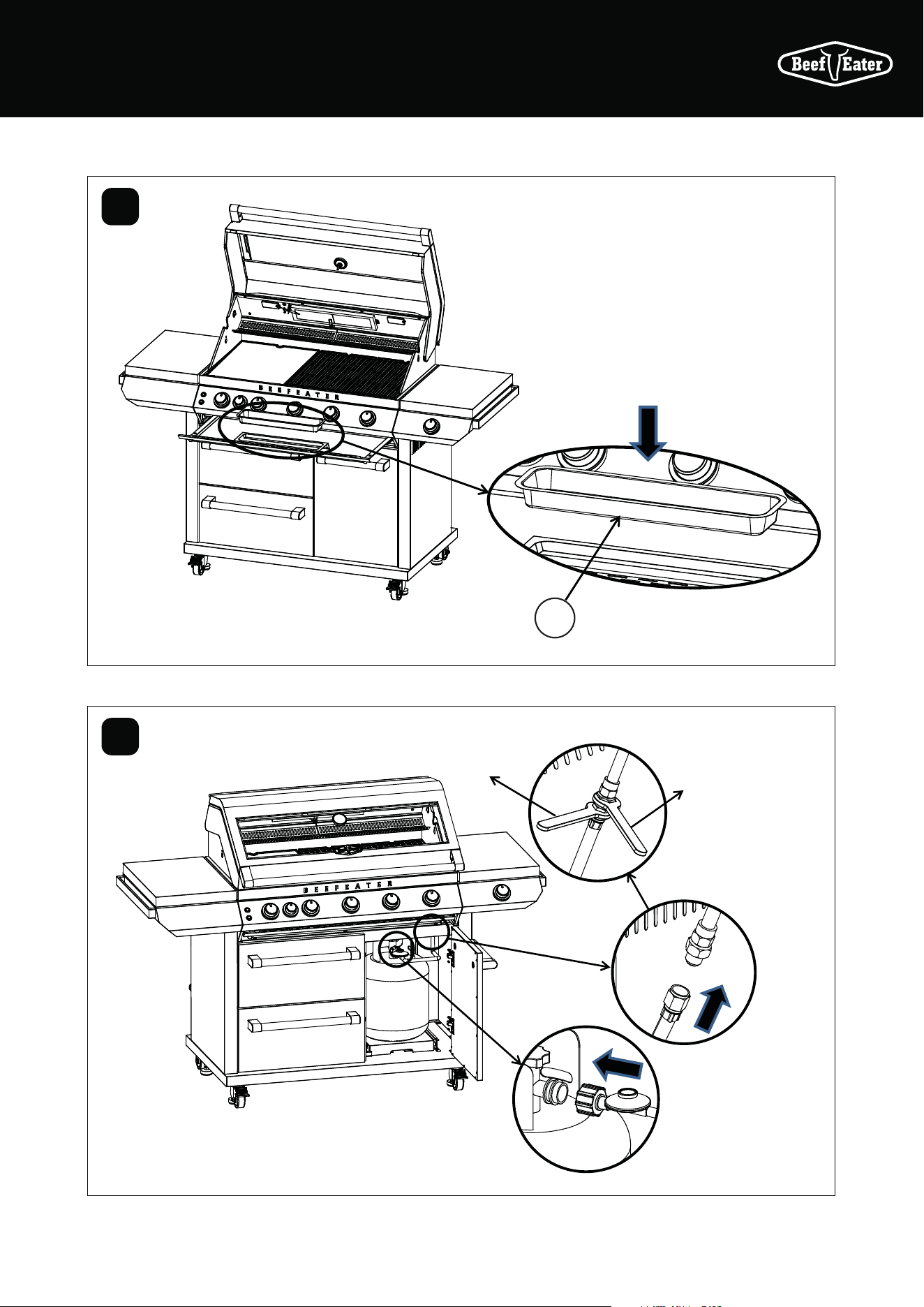
41
Turn to lock the
gas bottle tray
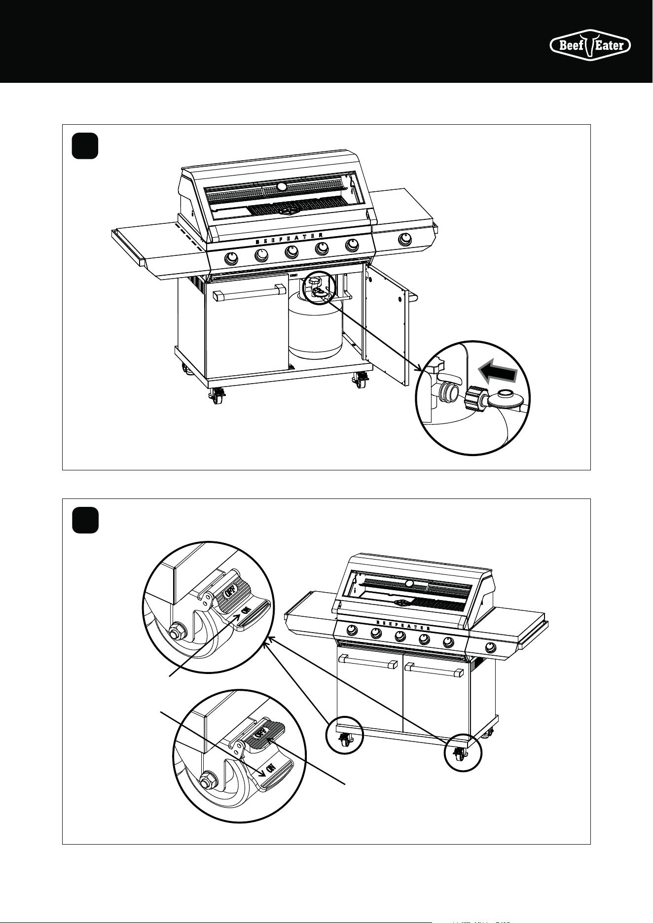
Leak test procedure
• Ensure all gas valves are in the ‘OFF’ position.
• In a small container, mix a solution of water and
detergent or soap.
• After connection of the hose, turn on the gas supply
at the gas bottle.
• Using a brush, apply the solution to all gas
connection points and look for bubbles forming.
• Bubbling will indicate a leak.
• Turn off the gas supply and re-tighten the joint.
Repeat the leak test.
• If the leak persists, turn off the gas at the bottle and
contact a licensed gas fitter to correct.
BMF7645SA & BMF7655SA ASSEMBLY
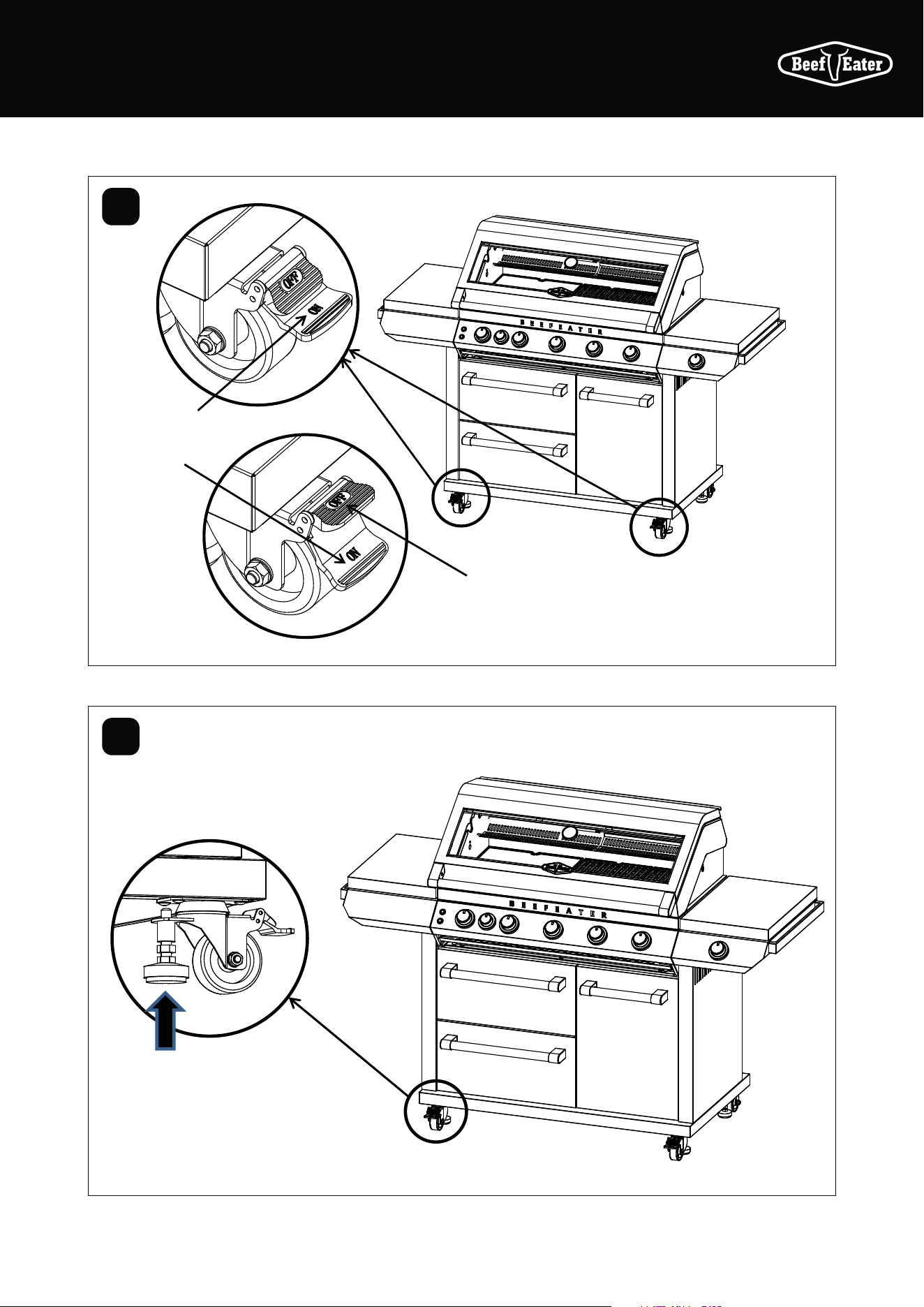
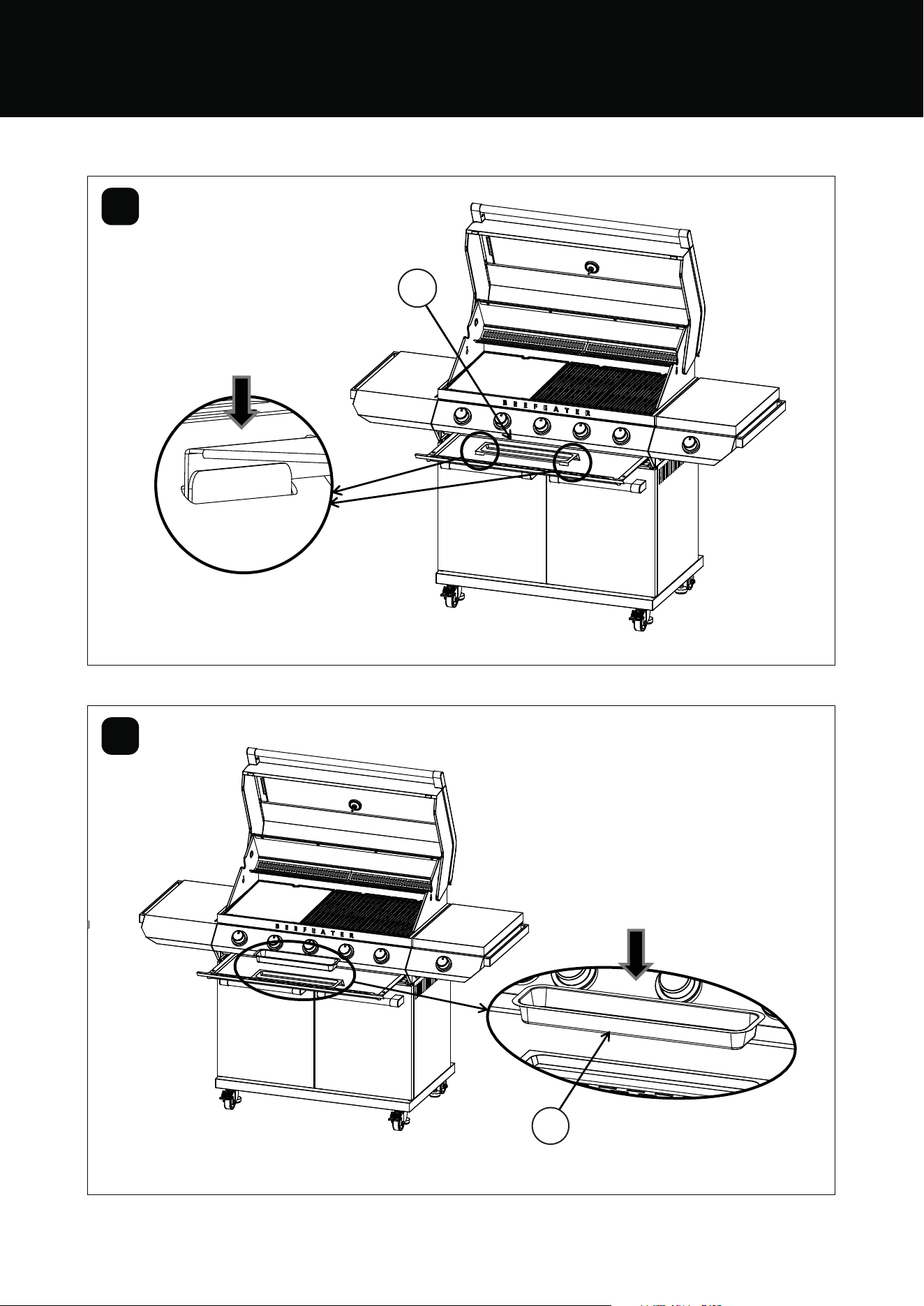
35ASSEMBLING THE BARBECUE
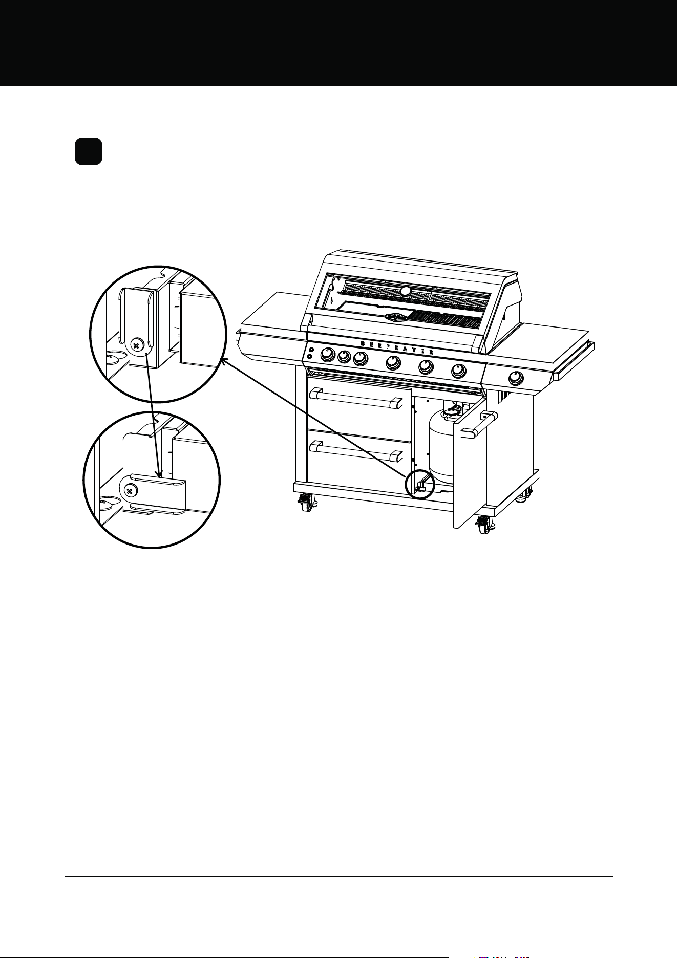
42
43
Push down “ON”
to brake
Push down
“OFF” to move
When moving the BBQ, it is necessary to raise the
leveling foot, and at the same time, it cannot touch
the fixed plate above, so as to avoid affecting the
rotation of the wheels
36 ASSEMBLING THE BARBECUE
BMG7642SA
BMG7625SA
BMG7642SA & BMG7652SA ASSEMBLY
For BMG7642SA & BMG7652SA
M6 x 12mm
M4 x 10mm
flat head
M4 x 10mm
countersunk head
x4x2x55
Tools required:
Hexagonal
screwdriver
Phillips
screwdriver
Wrench 22mm
Wrench 19mm
37ASSEMBLING THE BARBECUE
25
24
25
26
26
23
22
1
2
The hole is at the back
Attach 4 castors
Castor with
locks at the front
position
Castor with
locks at the front
position
M6 x 12mm
x 16
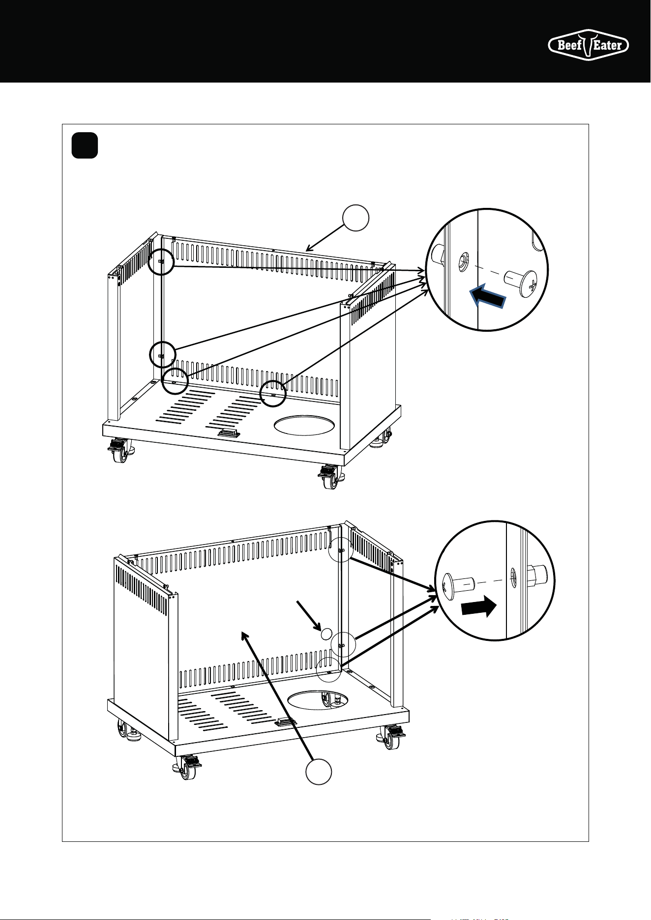
38 ASSEMBLING THE BARBECUE
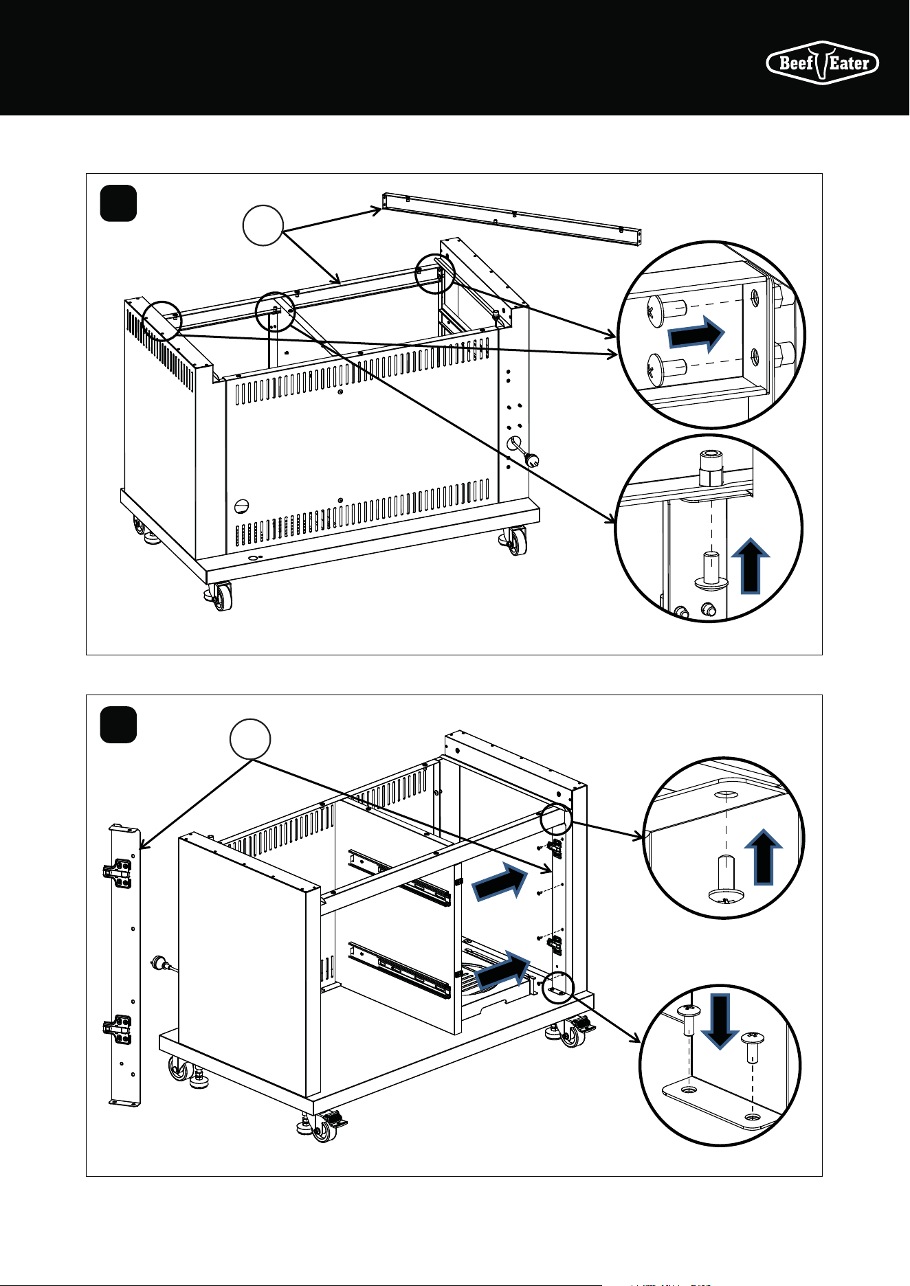
3
4
15
18
Assemble M6 head screw x6 , three on each side on
the trolley bottom panel, do not fully tighten.
Assemble left and the right side panels into the
keyholes then tighten screws
BMG7642SA & BMG7652SA ASSEMBLY
39ASSEMBLING THE BARBECUE
5
Assemble the back trolley panels with M6
head screws x7
11
11
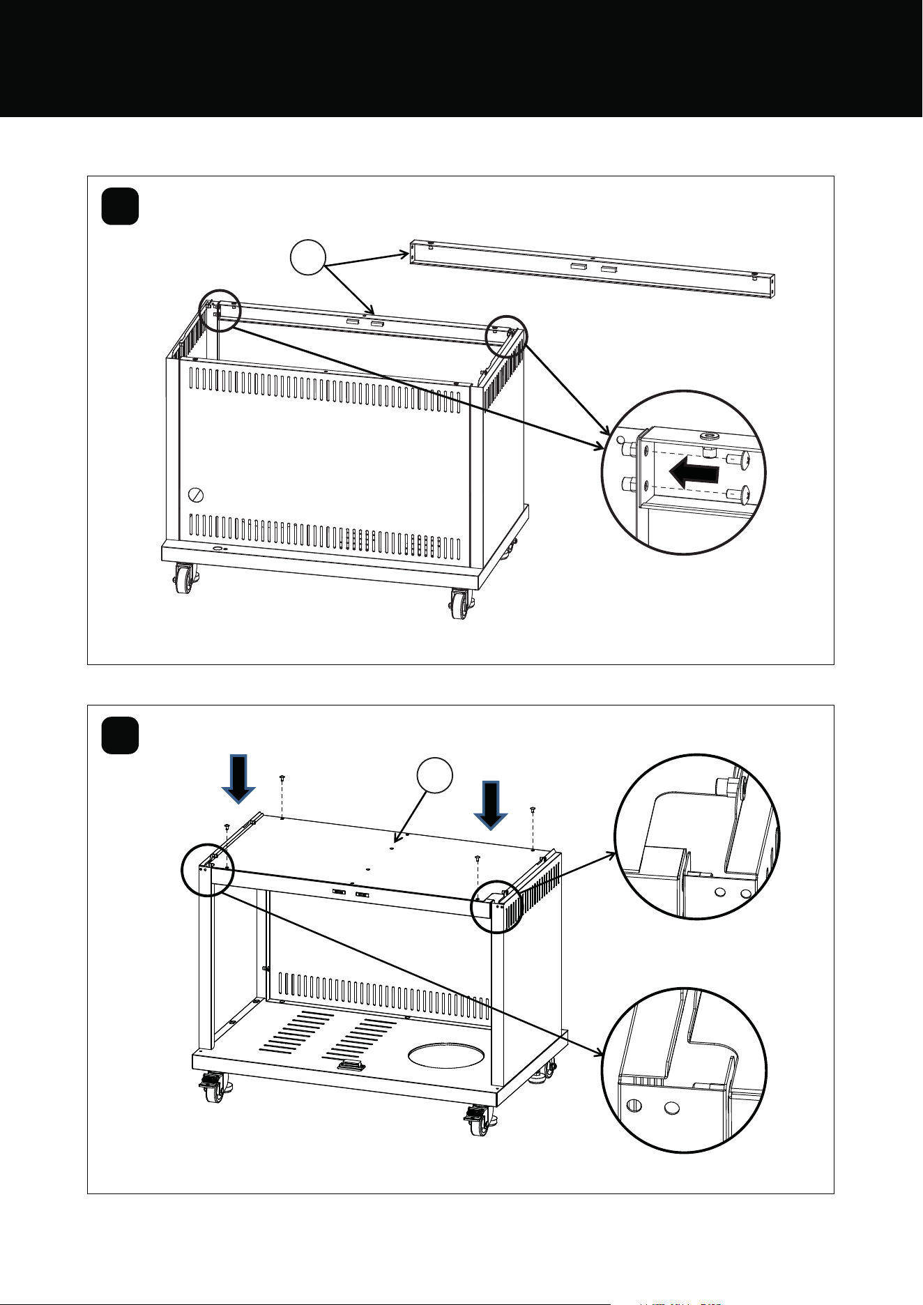
40 ASSEMBLING THE BARBECUE
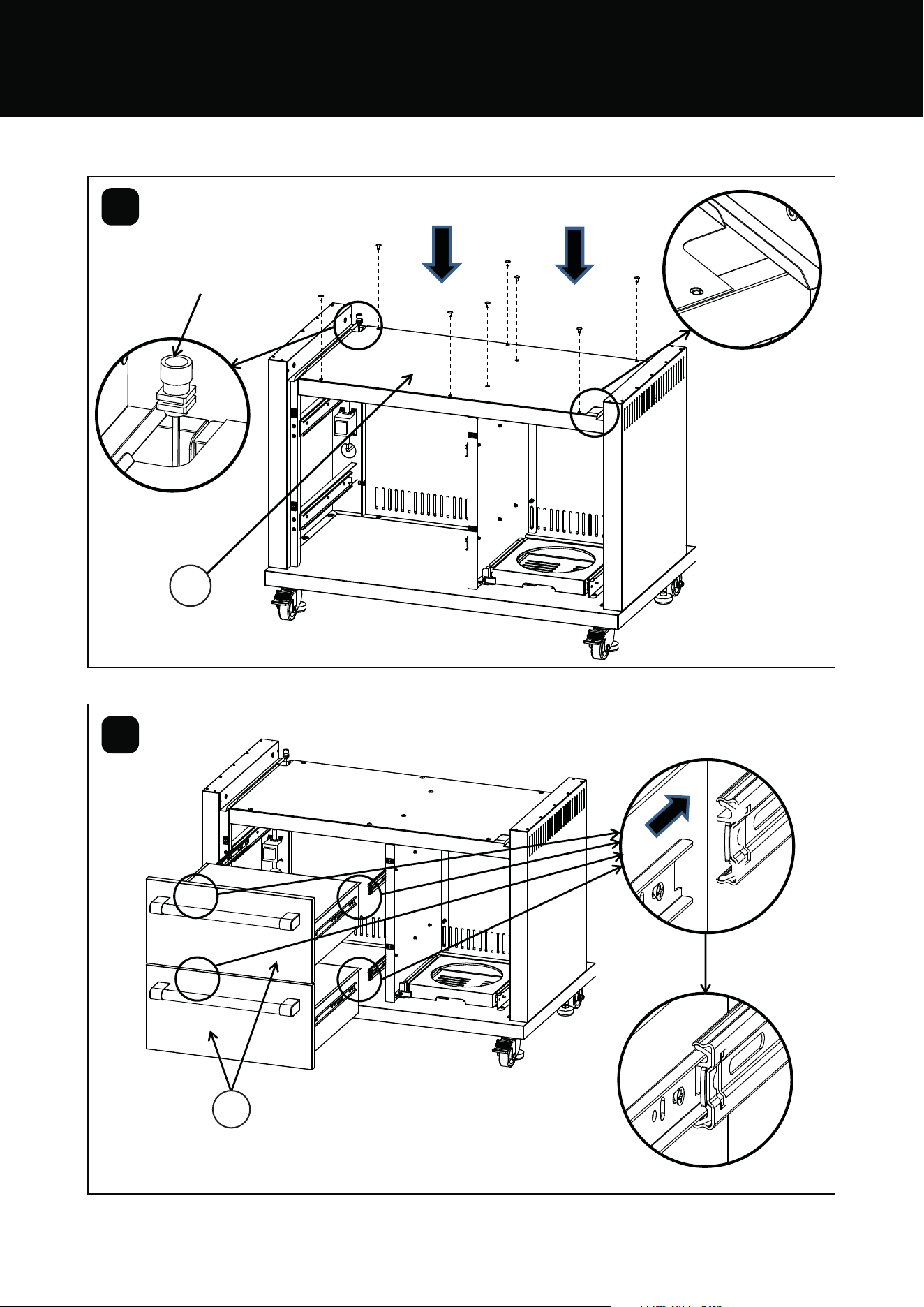
6
7
13
13
BMG7642SA & BMG7652SA ASSEMBLY
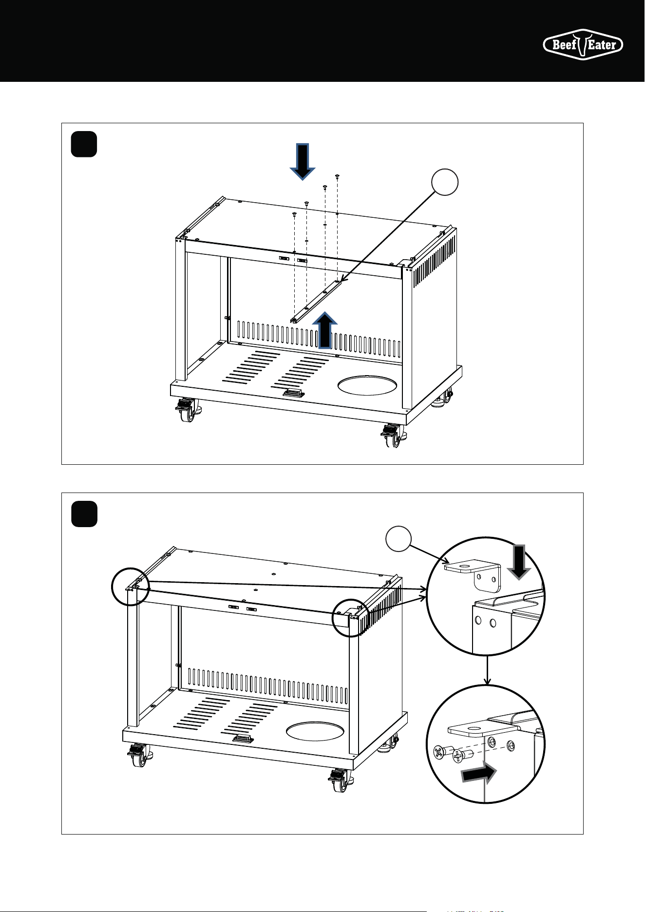
41ASSEMBLING THE BARBECUE
17
16
8
9
Assemble the trolley top panel with
M6 head screws x8
42 ASSEMBLING THE BARBECUE
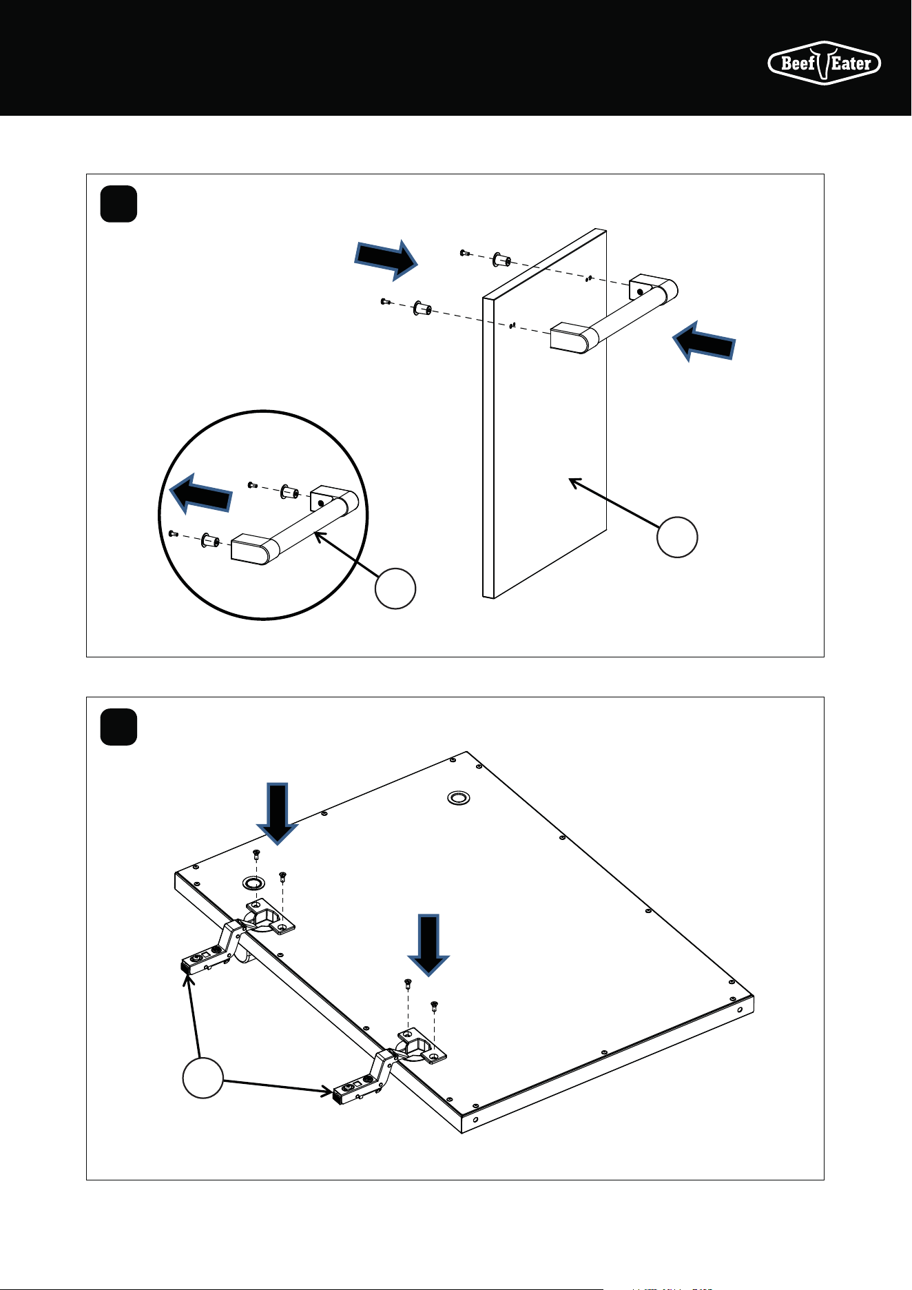
10
11
20
19
21
21
19
Assemble the door handle assy: remove the screws
from the handle then assemble the handle to door and
fix with screws
BMG7642SA & BMG7652SA ASSEMBLY
43ASSEMBLING THE BARBECUE
14
12
13
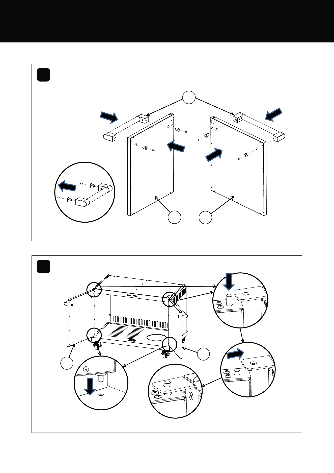
44 ASSEMBLING THE BARBECUE
14
15
BMG7642SA & BMG7652SA ASSEMBLY
45ASSEMBLING THE BARBECUE
7
6
16
17
Align side burner gas pipe through the hole, pull wire
through the hole
46 ASSEMBLING THE BARBECUE
18
19
BMG7642SA & BMG7652SA ASSEMBLY
47ASSEMBLING THE BARBECUE
4
20
21
48 ASSEMBLING THE BARBECUE
22
23
2
3
1
Drip hole should be
at front side
BMG7642SA & BMG7652SA ASSEMBLY
49ASSEMBLING THE BARBECUE
10
24
25
50 ASSEMBLING THE BARBECUE
26
27
9
8
Put on the foil box holder onto
the drip tray
Put the foil oil tray into
the holder
BMG7642SA & BMG7652SA ASSEMBLY
51ASSEMBLING THE BARBECUE
28
29
Push down
“ON” to brake
Push down “OFF”
to move
52 ASSEMBLING THE BARBECUE
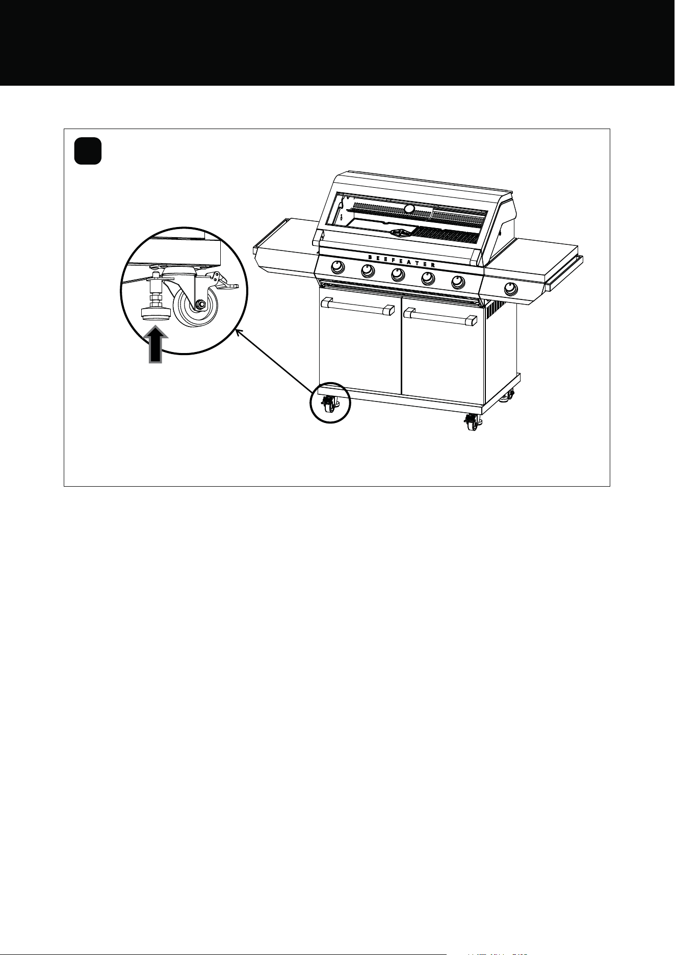
30
BMG7642SA & BMG7652SA ASSEMBLY
When moving the BBQ, it is necessary
to raise the leveling foot, and at the
same time, it cannot touch the fixed
plate above, so as to avoid affecting
the rotation of the wheels
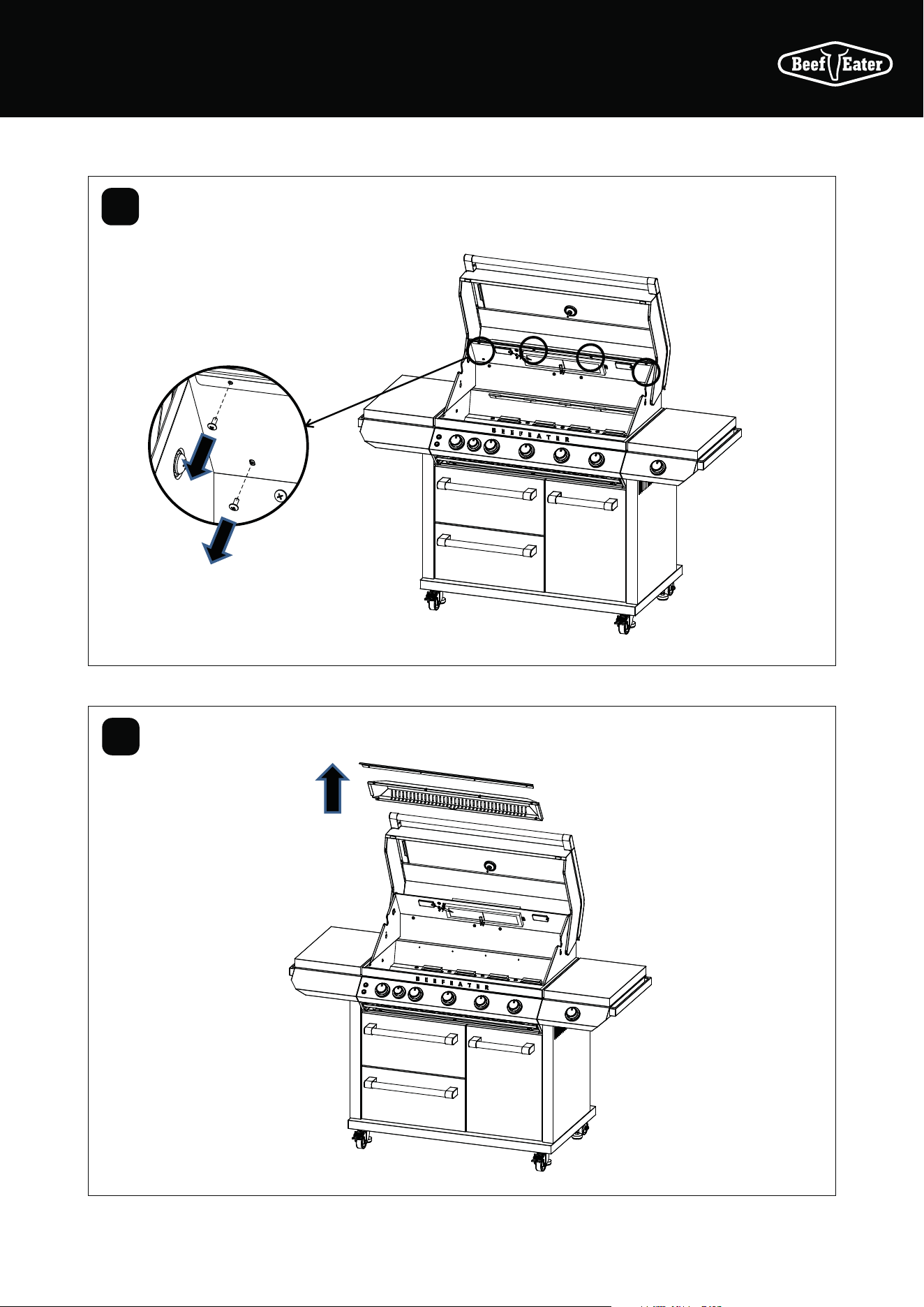
53NATURAL GAS INSTALLATION
NATURAL GAS INSTALLATION
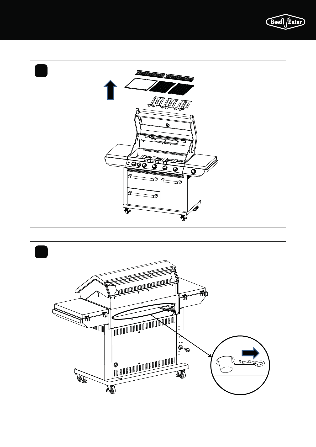
1
2
Take out the
warming rack,
cooking plate and
cooking grill
Disassemble the R latch
54 NATURAL GAS INSTALLATION
NATURAL GAS INSTALLATION
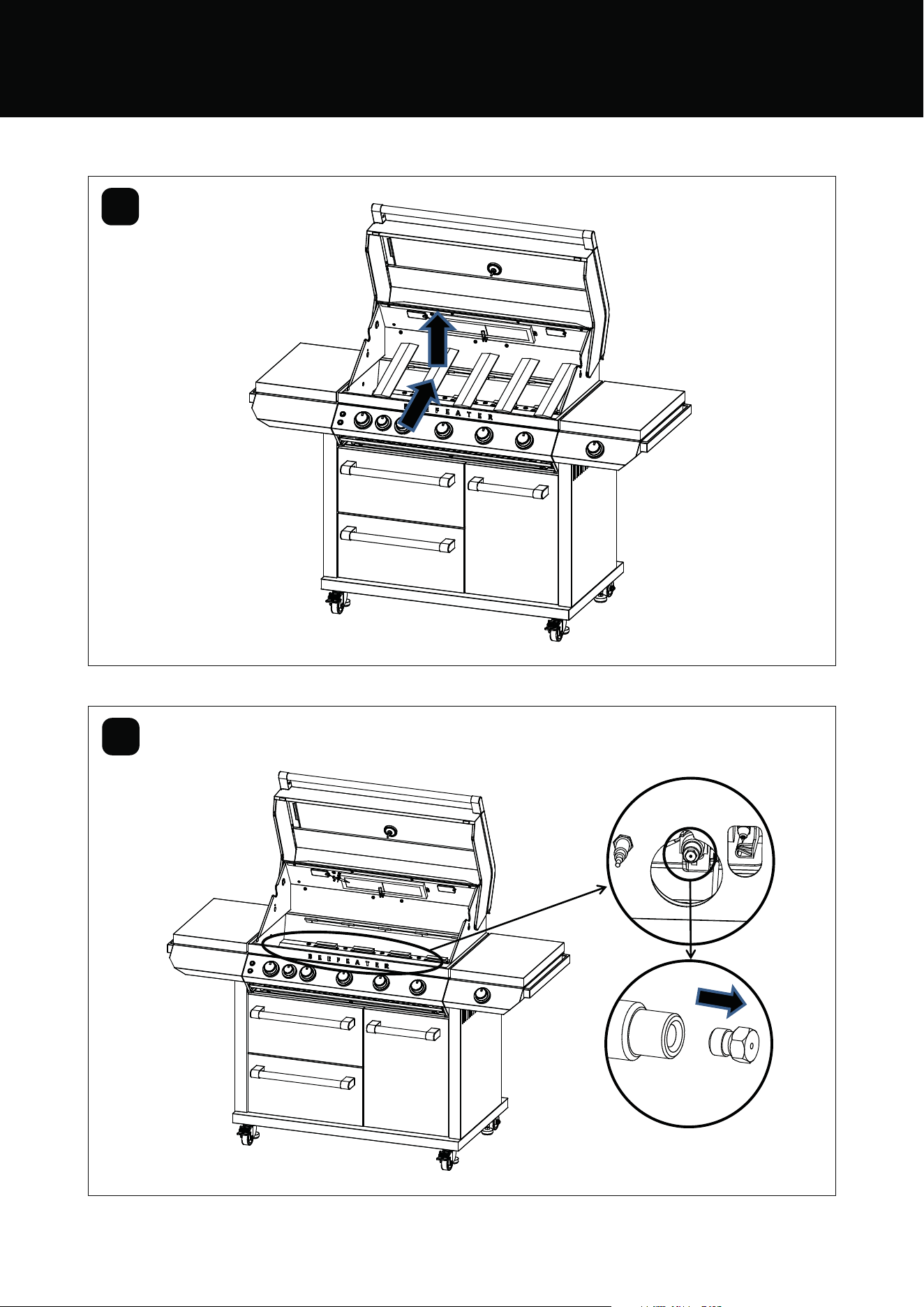
3
4
Take out the burners
Change the injector size for the NG Version
55NATURAL GAS INSTALLATION
5
6
Unscrew the 6 M4 head screws from the rear burner cover
Take out the front baffle
plate and the rear burner
cover
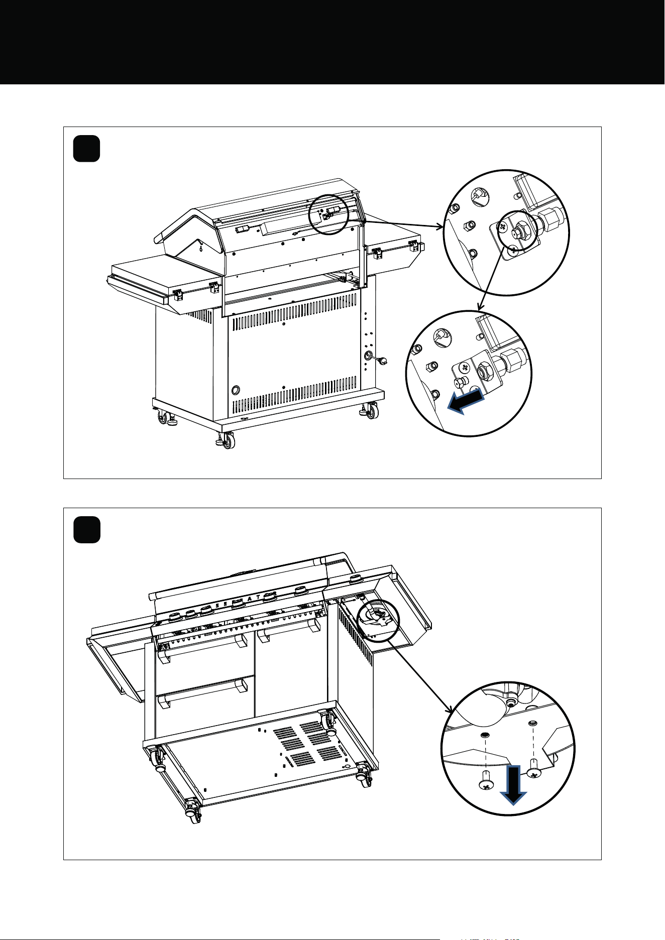
56 NATURAL GAS INSTALLATION
7
8
Change the injector size
Unscrew the M5 head screws x2 from the side table
NATURAL GAS INSTALLATION
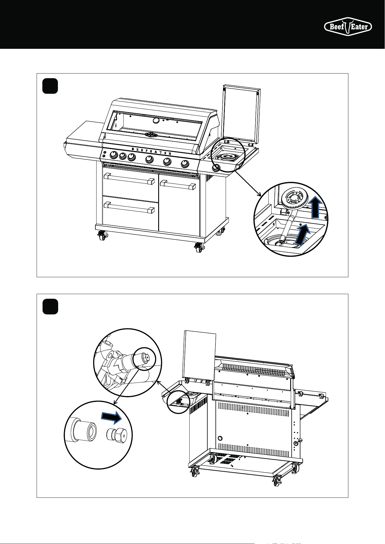
57NATURAL GAS INSTALLATION
9
10
Disassemble the side burner and change the
injector for the NG version
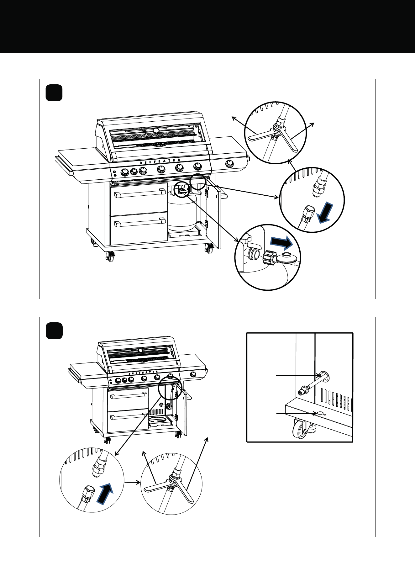
58 NATURAL GAS INSTALLATION
Spanner
19mm
Spanner
22mm
Spanner
19mm
Spanner
22mm
Tether
connection
point
Flexible
hose outlet
11
12
Change the injector size
NATURAL GAS INSTALLATION
Mobile restraint with hose assembly. When
the mobile barbecue is connected to a fixed
gas supply via a flexible hose connection, a
retaining tether of adequate strength shall
be fixed to the appliance and be suitable to
be fixed to the wall within 50mm of each
connection point. The retaining tether must
be less than 80% of the gas hose length.
59CONTENTSINSTALLATION
INSTALLATION
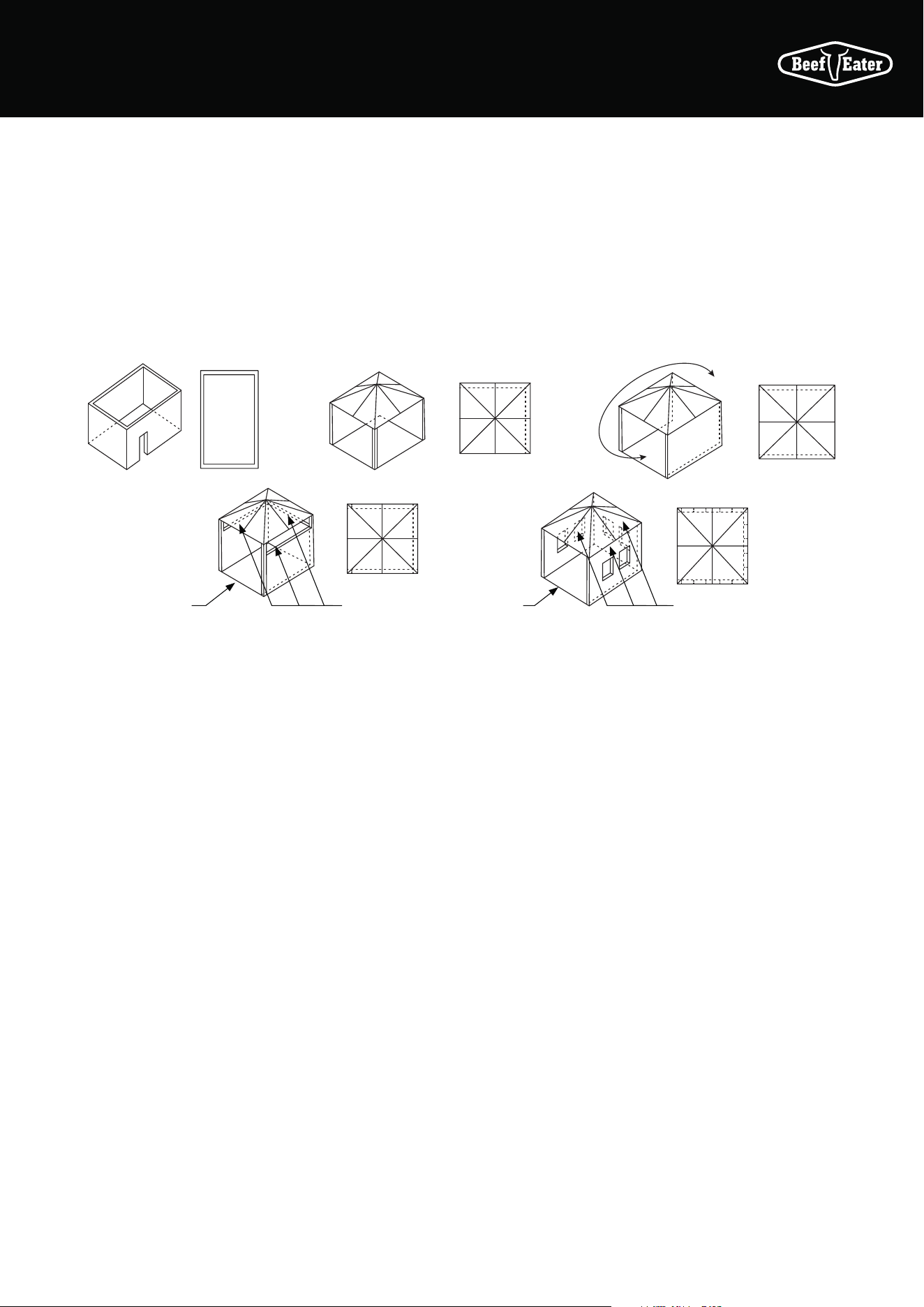
Partial Enclosures (Australia Only)
This appliance shall only be used in an above ground, open
air situation with natural ventilation, without stagnant areas,
where gas leakage and products of combustion are rapidly
dispersed by wind and natural convection. Any enclosure
in which the appliance is used shall comply with one of the
following:
Any enclosure in which the appliance is used shall comply
with one of the following:
An enclosure with walls on all sides, but at least one
permanent opening at ground level and no overhead cover.
Within a partial enclosure that includes an overhead cover
and no more than two walls.
The barbecue may be within a partial enclosure that includes
an overhead cover and more than two walls, the following
shall apply:
• At least 25% of the total wall area is completely open; and
• At least 30% of the remaining wall area is open and
unrestricted.
In the case of balconies, at least 20% of the total of the side,
back and front wall areas shall be and remain open and
unrestricted.
Both ends open
Open side at
least 25% of
total wall area
Open side at
least 25% of
total wall area
30% or more
in total of the
remaining wall
area is open and
unrestricted
30% or more
in total of the
remaining wall
area is open and
unrestricted
60 CONTENTS
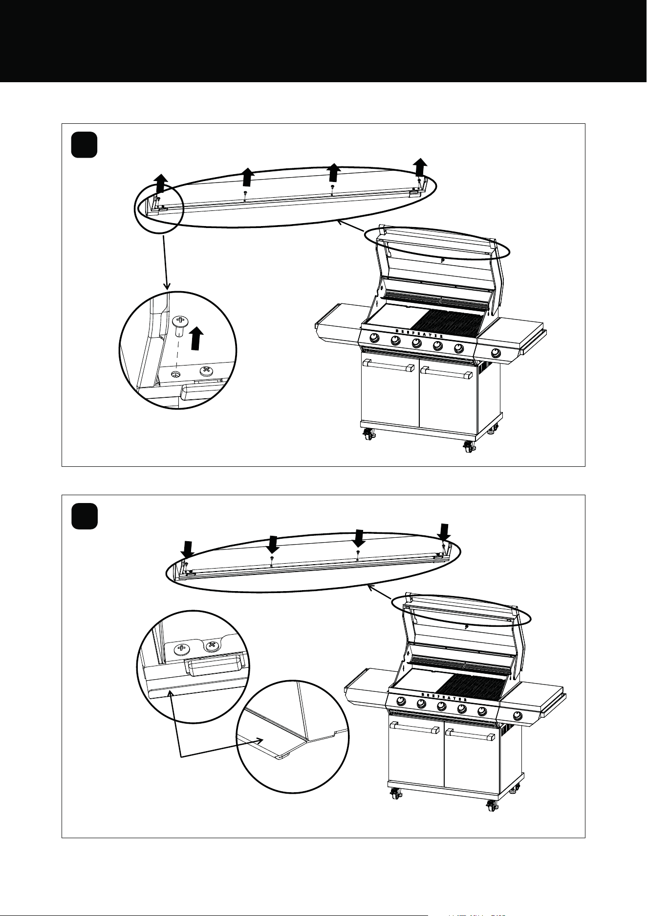
RAIN BAFFLE INSTALLATION
1
2
Remove the hood screw
M4 x 10mm (flat head screw 4 PCS)
Rain baffle
Assemble the rain baffle:
M4 x 10mm (flat head screw 4 PCS)
BMG7642SA and BMG7652SA
BMG7642SA and BMG7652SA
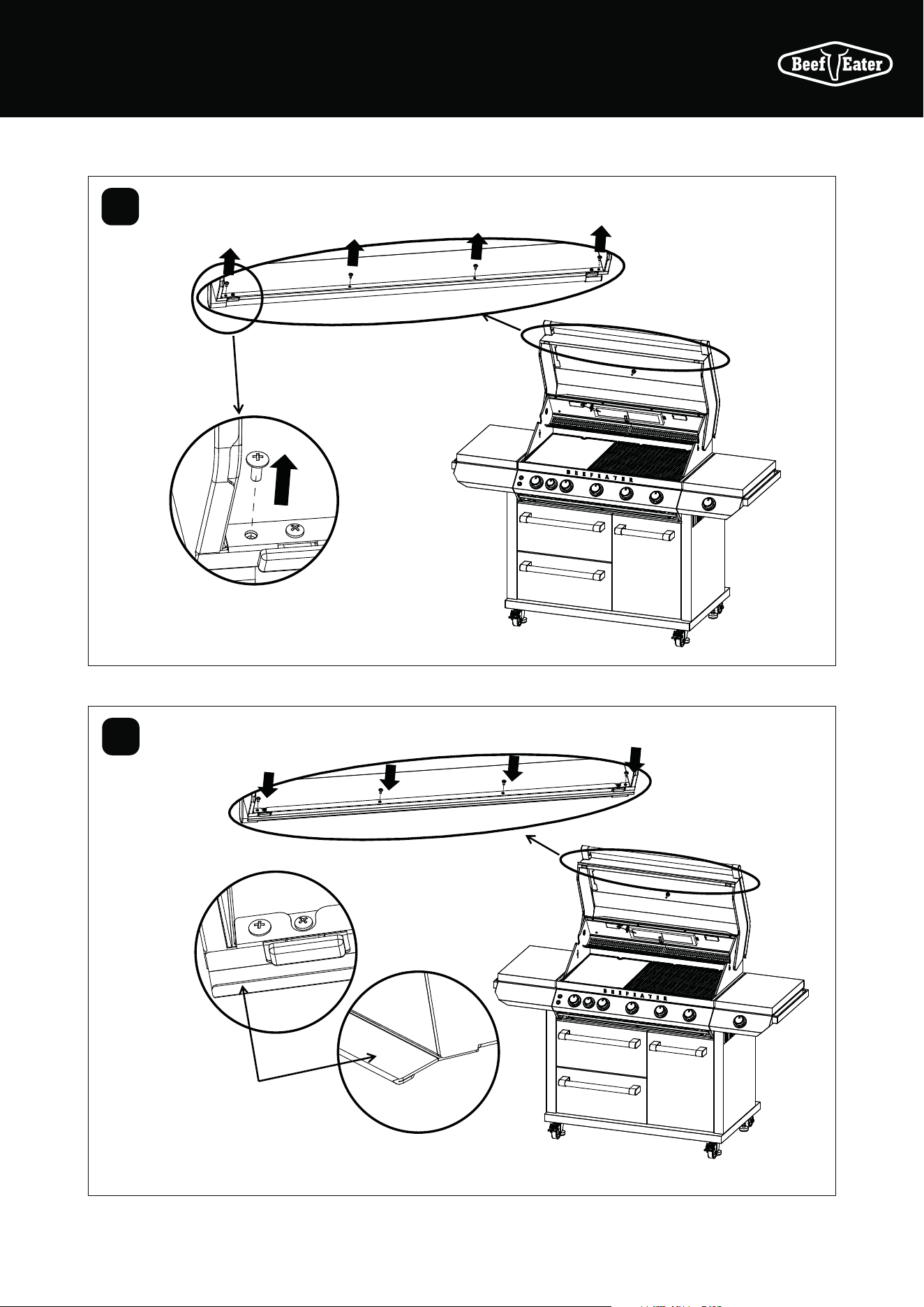
61CONTENTS
1
2
Remove the hood screw
M4 x 10mm (flat head screw 4 PCS)
Rain baffle
Assemble the rain baffle:
M4 x 10mm (flat head screw 4 PCS)
BMG7645SA and BMG7655SA
BMG7645SA and BMG7655SA
RAIN BAFFLE INSTALLATION
62 SIDE BURNER
SIDE BURNER OPERATING INSTRUCTIONS
Manual lighting
In the event of the automatic ignition system not working, the
barbecue can be lit manually
• Position the manual igniter next to the burner
• Depress the knob and rotate to ‘HIGH’
• The burner should light
• Do not attempt to manually light the burner for more
than 5 seconds
• If the burner did not light, depress the knob and turn
back to the ‘OFF’ position
• Allow several minutes for gas to disperse then repeat
lighting procedure
Lighting Instructions
1. Do not attempt to light burner with the cooking surfaces
covered
2. Read the instructions before lighting
3. To light burner depress knob and rotate to ‘HIGH’
4. Keep knob pushed in for 5 seconds to ensure flame
safety is activated (if fitted)
5. If burner did not light, turn knob to the ‘OFF’ position.
Allow gas to disperse, then repeat lighting procedure
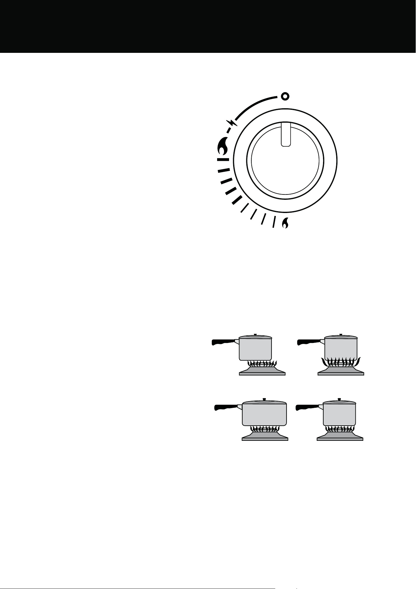
Using cookware on the side burner
Do not use oversized cookware or place cookware off-centre
over the burner as this can cause high temperatures in
control knob and surrounding panels. Cookware should
not exceed 200mm in diameter, the use of larger cookware
may cause damage to the appliance and is not covered
under warranty.
Correct
2
3
Incorrect – pan too large
Incorrect – pan not centred
22
Incorrect – flame too high
L
E
O
N
63INSTALLATION WARNINGS
INSTALLATION WARNINGS
Before You Begin
Check that the gas type is correct for your type of gas.
You will find the gas type label on the side of your barbecue.
If your barbecue is of the incorrect gas type, or if you are
unsure, consult your dealer before going any further.
This appliance must have a minimum clearance from
combustible materials of 610 mm (24”) on all sides of the
barbecue.
Do not install the appliance under or on any combustible
surface.
The appliance must be tested for safe and proper operation
on completion of installation.
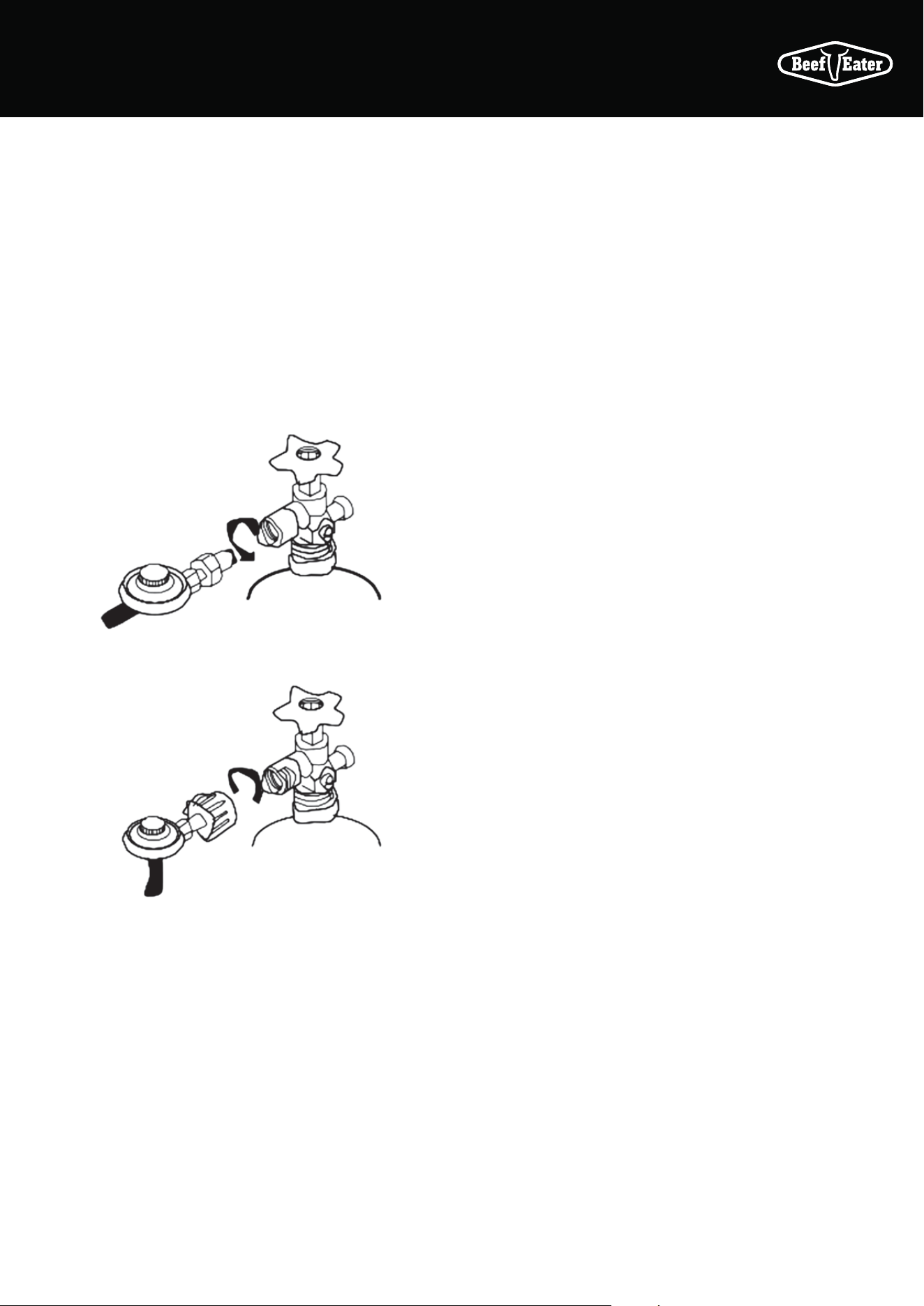
For Quick Connect cylinders, tighten
clockwise
For POL cylinders, tighten anti-
clockwise
Mobile Installation - Portable LP Gas/ Propane
Recommended minimum LPG/propane cylinder capacity
for use with this appliance is 4kg. Maximum LPG/propane
cylinder capacity for use with this appliance is 10kg. In the
USA, only a 20lb cylinder may be used.
Fit the regulator to the LPG/propane cylinder, as shown on
the right. Secure all joints spanner (wrench) tight but do not
over-
Fixed Installation - Portable LP Gas/Propane.
BeefEater LPG/propane barbecues are designed to operate
at 2.75Kpa (11”WC).
Connect the gas supply line to the barbecue inlet located on
the right side of the appliance using either hard plumbing,
or a flexible hose connected to a bayonet point, also known
as a quick connect fitting. Refer to AS 5601 or your local
installation code for pipe sizing details. Secure all joints
spanner (wrench) tight but do not over-tighten.
Test gas pressure by removing the last burner from the left
hand side of the barbecue and attaching a hose and pressure
gauge to the end of the gas valve. Turn on 2 burners and
check the pressure. Inlet pressure should be 11.0” WC or
2Ð75 kPa.
Fixed Installation - Natural Gas
(Natural Gas installation should be carried out by a qualified
gas fitter).
BeefEater Natural Gas barbecues are designed as low-
pressure appliances (4.0” WC, 1.00KPa).
Fit the natural gas regulator supplied directly to the
barbecue inlet located on the right side of the appliance
using either hard plumbing, or a flexible hose connected to a
bayonet point, also known as a quick connect fitting. Refer to
AS 5601 or your local installation code for pipe sizing details.
Secure all joints spanner (wrench) tight but do not over-
tighten.
Test gas pressure by removing the last burner from the left
hand side of the barbecue and attaching a hose and pressure
gauge to the end of the gas valve. Turn on 2 burners and
check the Manifold pressure should be 4.0” WC or 1.00 kPa.
Australia only (applies to all gas types) : Where a mobile
appliance is to be connected to a fixed gas supply via a
flexible hose connection, a retaining tether of adequate
strength shall be fixed to the appliance and be suitable to be
fixed to the wall within 50mm of each connection point. The
length of the tether shall not exceed 80% of the length of the
hose assembly. In this way, if the barbecue is accidentally
moved, the chain stops the barbecue from stretching the
hose. The barbecue appliance must be isolated from the
gas supply piping system by closing its manual shutoff valve
during any pressure testing of the gas supply piping system
The barbecue appliance must be isolated from the gas
supply piping system by closing its manual shutoff valve
during any pressure testing of the gas supply piping system.
Converting the unit to natural gas
NOTE: Refer to page 53-58 for natural gas installation
1. Turn off the gas supply valve on the gas cylinder. Ensure
that all gas controls on the BBQ are in the OFF position.
2. Disconnect the hose and regulator from the gas cylinder
and disconnect the gas hose from the barbecue gas inlet
using a 19mm open-ended spanner/wrench.
3. Open hood and remove all cooking plates, grills and
vaporisers from the BBQ.
4. Remove the ‘R’ shaped locking clips that hold each
burner in place and remove all burners from barbecue.
This needs to be done at the on the front firewall of the
BBQ.
5. The gas injector (also known as jets or nozzles) for each
burner are located within deep pockets at the on the
front firewall of the BBQ.
6. Remove each gas injector from the end of each jet
holder using a 6mm socket spanner/wrench, turning
gently in a counter clockwise direction. Be careful not
to block the orifice at the end of valve where the gas
injector is fitted and do not remove any of the thread
sealing compound from the orifice where the injector is
located.
7. Check the identification mark stamped on Hex Head
of the injector to confirm that it is the correct size (NG:
2.10mm) Screw correct Jet back into place.
8. When fitting the NG gas injectors to the end of the jet
holder be sure to seat the injector correctly on the
thread before turning it in a clockwise direction until it is
seated firmly in place. Do not over-tighten.
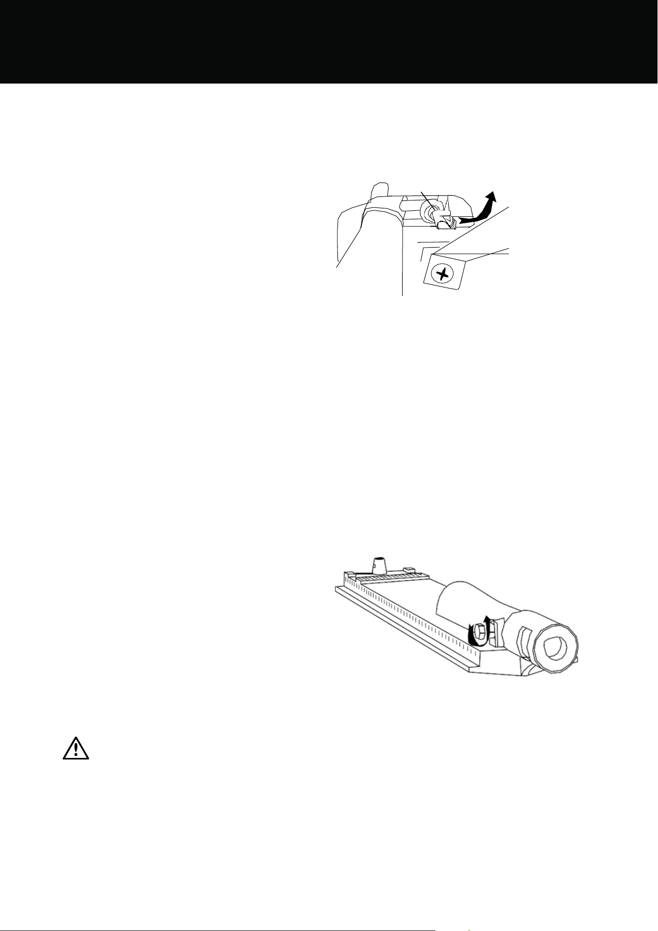
IMPORTANT
Please note: for SL4000 side burners
One the side burner valve, from the inside bend the pilot
ignition tube out the way, unscrew the pilot jet and replace
with the 0.95mm NG jet supplied with the conversion kit.
Once done bend the tube back to the original position if
necessary.
9. Replace all parts into position in the BBQ. Remove the
chute before changing the nozzle and then replace it
when done.
Pilot
Ben
10. Refit the burners and secure with the locking clips that
hold each burner in position. Replace the vaporisers,
grills and cooking plates. Check the operation of each
burner - on some models it may be necessary to open
the air-mixture screw (located at the burner venturi) a
couple of turns to get the correct flame.
11. Replace the LPG gas type label with the natural gas
label supplied.
12. Connect the natural gas hose and regulator (where
applicable) to the gas inlet on the barbecue. Tighten
firmly but do not over tighten. Connect gas regulator
to gas source line. Perform leak testing using same
procedure as for LPG on page 68.
13. For mobile units attach restraining tether to anchor
point on barbecue, and fasten within 50mm of fixed gas
outlet with suitable fastener. Ensure the length of the
tether does not exceed 80% of the length of the hose to
the fixed gas supply outlet.
INSTALLATION WARNINGS
64 INSTALLATION WARNINGS
GAS SPECIFICATIONS AND MOBILE RESTRAINT
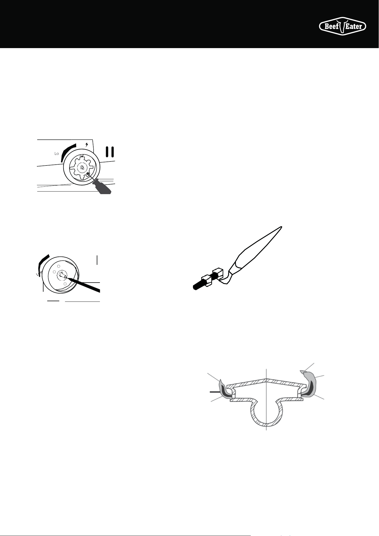
Turn down adjustment
• When converting to natural gas the turndown setting will
need to be adjusted to give a satisfactory flame on low
setting on each burner.
• Remove knob from valve shafts. For ignition valve the
low flame adjustment screw is located on the lower right
hand corner of the front of the valve body
Of
• Fully insert and rotate a flat bladed screwdriver to adjust
turndown.
• For non-ignition valves the screw is located inside the
knob spindle. Use a 2.5mm wide flat blade screwdriver
full inserted and make a 3/4 turn counter clockwise.
• After leak testing light one burner and set to high.
• One burner at a time turn the valve shaft to lowest
setting observe the flame to ensure a small steady
flame in achieved.
• Repeat for the other burners.
• Turn off burners and replace control knobs, ensuring the
knob is in the correct orientation when valve is in “OFF”
position.
Secure all joints and leak test
Never use a naked flame to check for gas leaks. The gas
leak testing procedure should be conducted every time a gas
cylinder is refilled and reconnected to the appliance, or after
any new gas connection is made.
In a small container, mix up a solution of water and
detergent or soap. Mix the solution well.
For LPG/propane make sure that the gas supply valve on the
gas cylinder is turned on. For Natural Gas make sure that
the gas shutoff valve is on.
Make sure that the gas control valves on the appliance are all
turned off.
Using a brush or spray bottle apply the solution to the gas
line and each joint in the gas line.
Bubbling of the solution will indicate that there is a leak
present. Re-tighten or re-seal any joints that are leaking.
If a leak persists contact your distributor or the manufacturer
for assistance.
Check proper burner operation
Following operating instructions, light each burner and
check for a clear blue flame with just a tip of yellow. Excess
yellow tipping can be adjusted using the burner adjustment
screw on the side of the burner. Turn the screw in an anti-
clockwise rotation to reduce the yellow.
Yellow
tipping
Yellow
tipping
Right Wrong
Light
blue
Light
blue
Dark
blue
Dark
blue
65INSTALLATION WARNINGS
Before you light the barbecue
Perform the following checks
• Make sure all gas connections are tight and leak tested
• Ensure the cooking surfaces are clean and hygienic
• Check the control knobs are in the off position
• Check that the gas supply is turned on
• Ensure the hood of the barbecue and the lid of the side
burner are up. If you do not, gases can build up inside
the hood and create a dangerous situation
• Make sure long handles do not hang over the edge of
the barbecue. Injury can result if they are accidentally
knocked
Grease tray
Neatly line the grease tray with a couple of sheets of
aluminium foil to aid in clean up. Cut the foil to shape and
make sure that the foil sits on the bottom of the tray.
Fill the tray with a 6mm (1/4”) layer of dry sand or other non-
combustible absorbent material to absorb grease. Change
the foil and absorbent material regularly to reduce the
likelihood of a grease tray fire.
Lighting the barbecue
The same procedure is used to light the main burners as
well as the side burner:
1. Push in and hold the control knob down while turning
slowly in an anti-clockwise direction until the starter
mechanism engages at the two o’clock position. At this
time the gas will start to flow.
2. Hold the control knob in while continuing to turn the
knob toward the High or twelve o’clock position
3. The starter mechanism will click and the main burner
will now light. Continue turning the knob slowly until it
rests in the twelve o’clock position
If the burner is alight, release the knob
The requirement to press the knob in before turning
is a safety feature that prevents the knobs from being
accidentally turned on.
If the burner does not light
Keep the control knob pushed in and turn the control knob
in a clockwise direction to return to the OFF position. Wait
5 minutes for the gas to disperse and then repeat steps
1-3. If you cannot light the burners, call your retailer before
proceeding.
Manual lighting
Press and turn the left hand control knob anti-clockwise to
the High position, then use a long match to light the left hand
burner immediately through the gap between the front of the
grease tray and the barbecue body.
HIGH
GAS SPECIFICATIONS AND MOBILE RESTRAINT
66 INSTALLATION WARNINGS
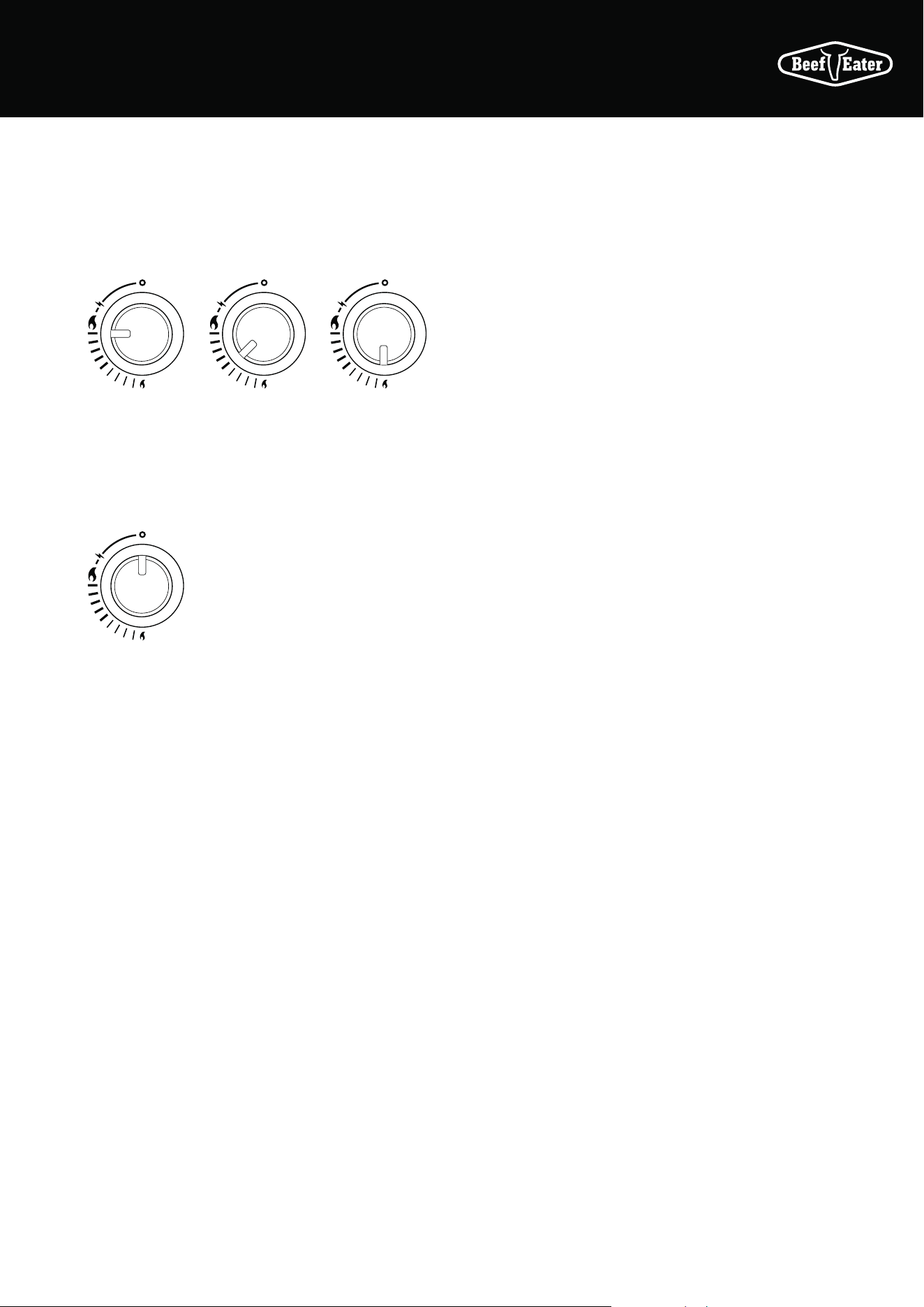
Controlling The Burners
The control knob can now be turned to the desired heat
setting, Low, Medium or High. The control knob does not
need to be pushed in while selecting the heat setting.
HIGH
MEDIUM LOW
To Turn Off The Burner
Push in and hold the control knob while turning in a
clockwise direction until the Off position is reached.
OFF
After Use
It is a good idea to leave the barbecue on for about 10
minutes after you have finished cooking. This helps to burn
away any excess food residues and oil, and makes cleaning
easier.
1. Be sure to turn off all control knobs and the cylinder
valve (for LPG/propane) or shut-off valve (for Natural
Gas)
2. Allow barbecue to cool
3. Clean the drip tray and cooking surfaces
4. Clean any food spills from the side burner
5. Lower the hood and side burner lid
Remove the gas cylinder from the enclosure before
disconnecting the gas line from the appliance. Tighten
all connections before placing the gas cylinder back in its
enclosure.
67INSTALLATION WARNINGS
CARE AND MAINTENANCE
This appliance should be checked and serviced by an
authorised service person every 2 years to ensure the
appliance remains in a safe operating condition. (These
services are not covered by warranty). Spare parts are
available from your retailer or the manufacturer.
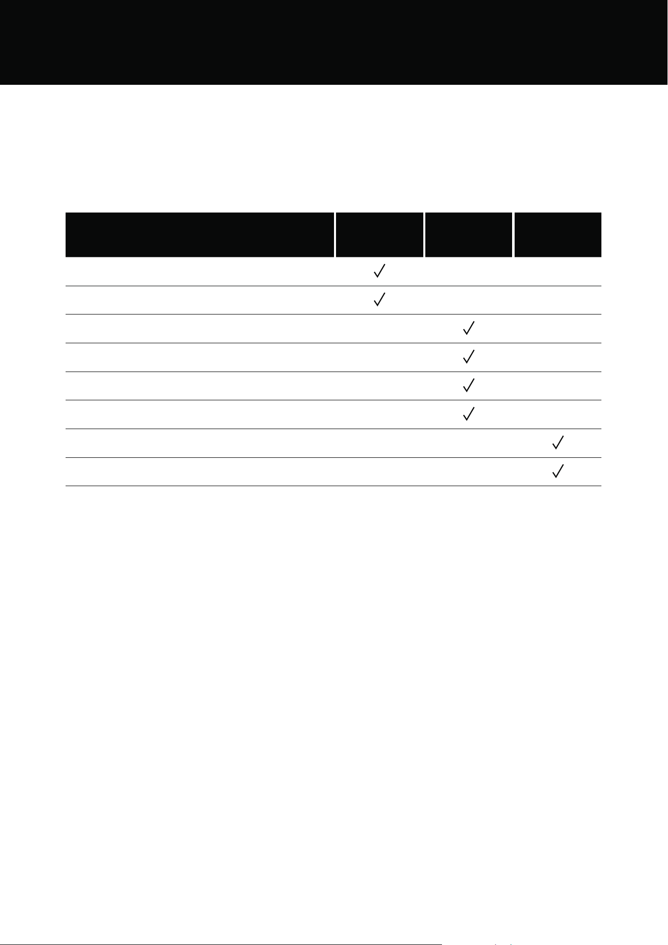
FREQUENCY
SERVICE AND MAINTENANCE EACH USE EVERY SIX MONTHS
BY AUTHORISED
SERVICE PERSON
EVERY 2 YEARS
Check all hoses for cracks and leaks
Check that all gas connections are tight
Clean entire barbecue thoroughly
Check and tighten all bolts on barbecue and cart
Clean and inspect vaporizers and reflectors
Clean and inspect barbecue burners
Clean and inspect gas injectors and control valves
Check working of ignition system
68 CARE AND MAINTENANCE
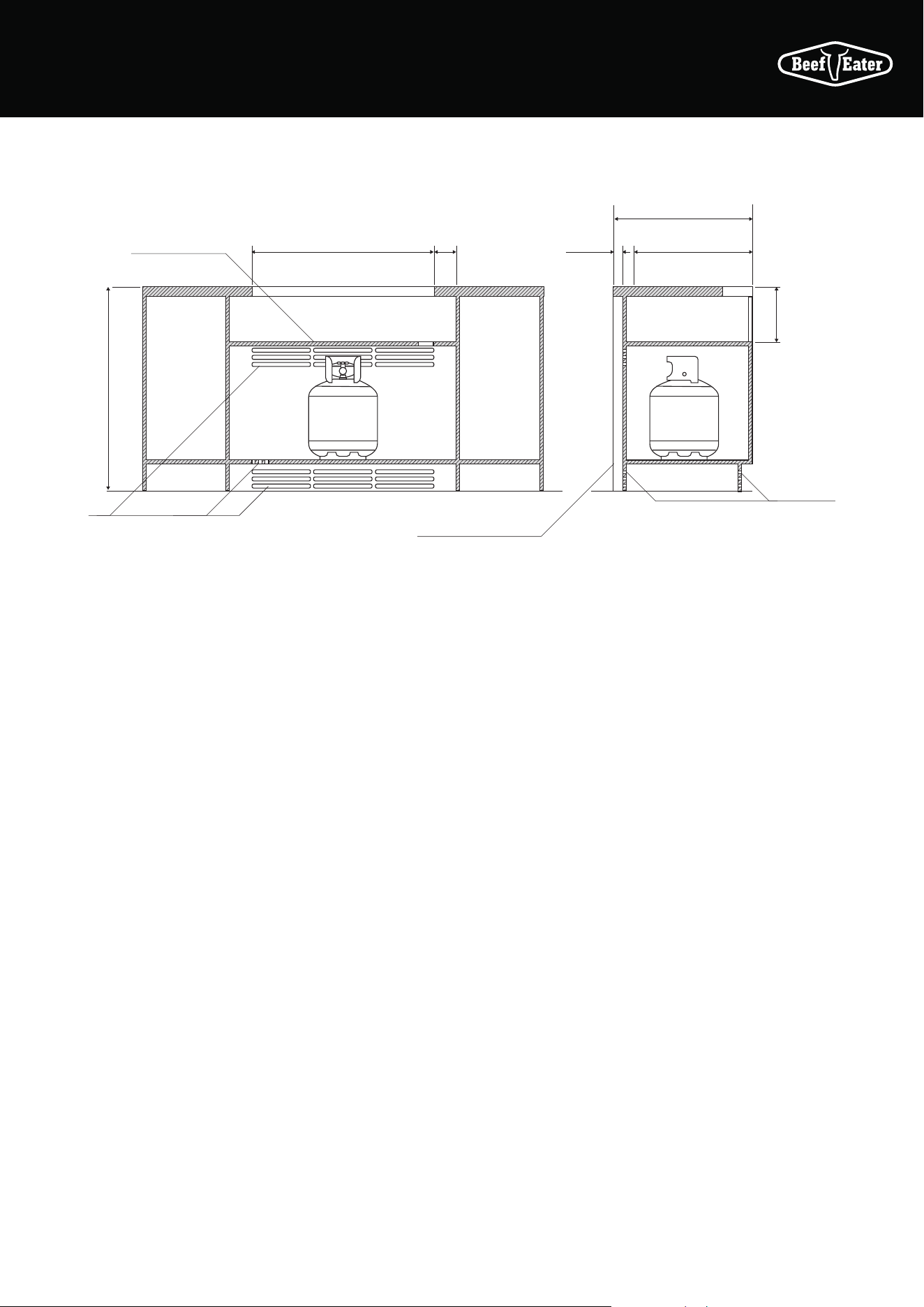
MOUNTING ENCLOSURE GUIDELINES
Enclosure construction
• All materials used for the construction of the enclosure
and gas bottle compartment must be non-combustible
• A 40mm min. gap between the enclosure and rear wall
is required. This allows for venting of the gas bottle
compartment. Vents should also be positioned at the
front of the enclosure
• The cutout size specified above allows for a 20mm gap
between the bottom of the barbecue and the separation
panel as well as a 20mm gap between the back of the
barbecue and benchtop. These gaps are necessary for
maintaining air flow around the barbecue
Gas bottle compartment ventilation requirements
AS5601 ventilation requirements for 9kg cylinder storage are:
• Where of sheet metal or similar impervious construction
there shall be ventilation openings at the top and bottom
of the enclosure or recess, each opening providing a free
area of at least 200cm
2
for every cylinder enclosed
• For LPG installations having enclosed cabinetry below
the separation panel that does not contain a gas bottle,
low level venting must be installed. This is to allow
the gas which is heavier than air to escape from the
enclosure in the situation where there may be a leak.
A minimum opening of 200cm
2
is required
Separation panel
930mm min.
Gas bottle venting slots
Rear wall/splashback to be
non-combustible material
Gas bottle
venting slots
828mm 4 burner
1006mm 5 burner
100mm
min.
40mm
gap min.
630mm min.
540mm
250mm
69MOUNTING ENCLOSURE GUIDELINES
OPERATING INSTRUCTIONS
Control functions
Before lighting the barbecue:
• Check that all hoses and gas fittings are tight
• Open the roasting hood
• Check all control knobs are in the ‘OFF’ position
• Ensure that the cooking surfaces are clean
• Turn the gas isolation valve ‘ON’
Lighting instructions
• Do not attempt to light burners with the cooking
surfaces covered
• Read instructions before lighting
• To light a burner,depress the knob and rotate to
. The
starter mechanism will click and the burner will light
• If burner did not light, depress knob and turn back to the
‘OFF’ position
• Allow several minutes for gas to disperse then repeat
lighting procedure
• Once ignited, the knob can then be turned to the desired
heat setting. The knob does not need to be pushed in
while selecting the heat setting
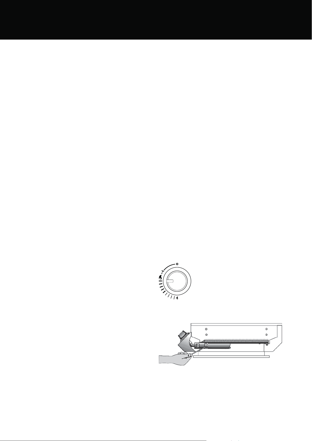
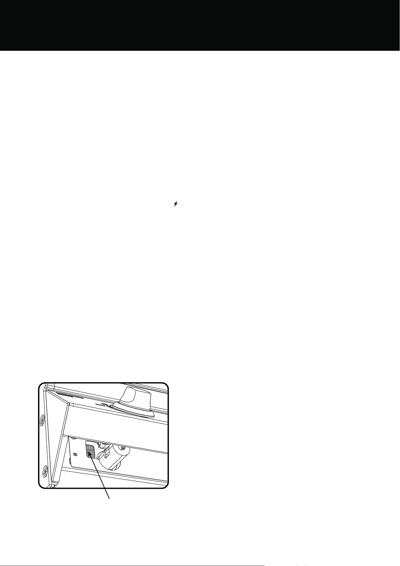
Manual lighting
• If,in the event of the automatic ignition system not
working, the barbecue can be lit manually
• To light manually, firstly slide out the grease tray to get
access to the lighting hole. Pass the manual ignitor
through the lighting hole and up towards the burner.
Then rotate the knob to ignite. If ignition fails,turn the
knob to ‘OFF’ and allow several minutes for the gas to
disperse before attempting to light again
• Once alight, repeat for other burners as required
Manual lighting hole
To turn the burners off
• When the cooking is complete, push the knob in and
rotate clockwise back to the ‘OFF’ position
Preheating
For best cooking results it is recommended to preheat the
barbecue prior to cooking.
• This barbecue is fitted with high power burners. In
most conditions it will only be necessary to preheat the
barbecue for 5 minutes before cooking can commence
• As with most things, experience will familiarise you
with the time required to achieve the desired cooking
temperature
.• If the unit does not operate correctly refer to
troubleshooting section
Cooking methods:
Direct Cooking Method
Commonly used for traditional barbecuing. Place food over
the lit grill section. Excess flaring may occur, so care must
be taken while cooking. Check inside the roasting hood
regularly. The direct cooking method is recommended for
steaks, chops, sausages, and hamburgers.
Indirect Cooking
This method of cooking applies only if you have a roasting
hood.
Indirect cooking involves little or no heat directly underneath
the food. Instead, the food is placed on the grill, the burners
below the food are turned off or Low, and burners on either
side are used. The hood is closed to trap heat and moisture.
With this method, heat circulates around the food, cooking
by convection. By trapping the vapour inside your “outdoor
oven”, the cooking vapour will fall back on the food on all
sides, not just from underneath. The food cooks more evenly,
and stays moist in the process.
Indirect cooking is similar to using a conventional oven and
is recommended for rotisserie cooking, roasts, poultry,
casseroles, vegetables and whole fish.
When cooking a roast, it is a good idea to use a roast holder
and baking dish. Always use a baking dish with a depth
greater than 35mm. Shallower trays may fill quickly and
overflow, which may cause a fat fire.
70 OPERATING INSTRUCTIONS
Reposition the grill plates
To achieve the best heat circulation around the food, it is best
to remove the hotplate from the barbecue and position the
two grill plates in the centre. Reposition the vaporisers from
above the 2 outside burners to above the inside burners.
This will give unrestricted heat circulation from the 2 outside
burners.
Preheating your Barbecue
Like an oven,preheating your barbecue before cooking
produces better results. Because your hood retains heat so
efficiently, preheating your barbecue is quicker with the hood
down.
Turn all burners to high. Close the hood, and allow to
preheat for about 5 minutes. Then reduce the burner
settings to achieve and maintain the required temperature,
by following these guidelines.
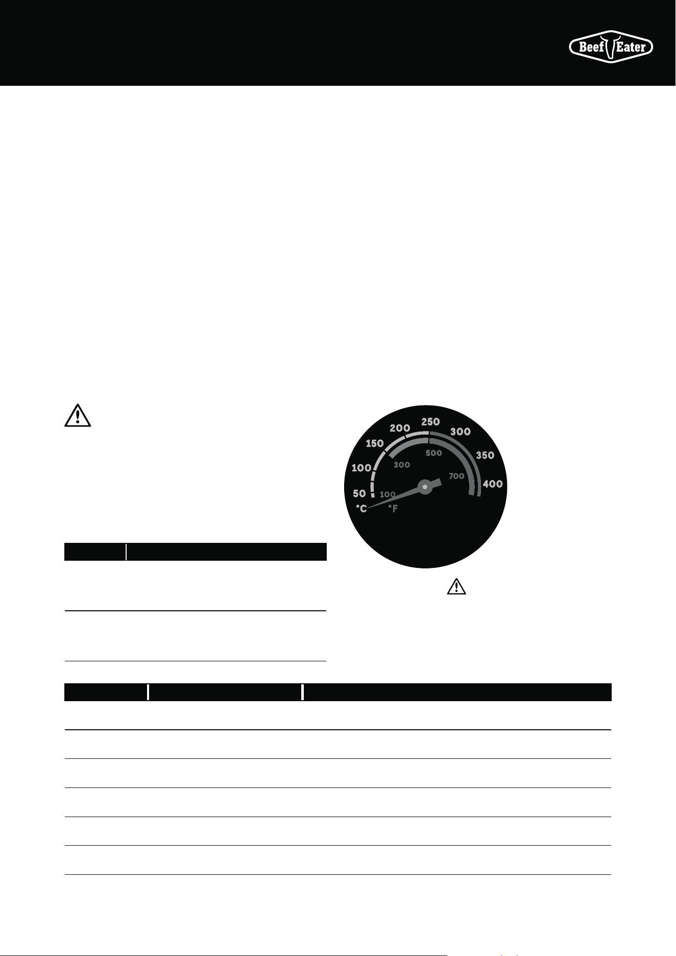
Maintain the right cooking temperature
CAUTION
Do not exceed the temperature warning on the temperature
gauge. Operating the barbecue above this temperature may
cause damage to the appliance. Your hood is designed to
keep the heat in, so requires constant monitoring.
These two charts tell you how hot and how long to cook
various types of meat, and the approximate burner settings
to help you achieve these results.
MODEL BURNERS
Four
burner
Two inside burners off
Two outside burners to medium
Five
burner
Three inside burners off
One outside burner to high
Other outside burner to medium
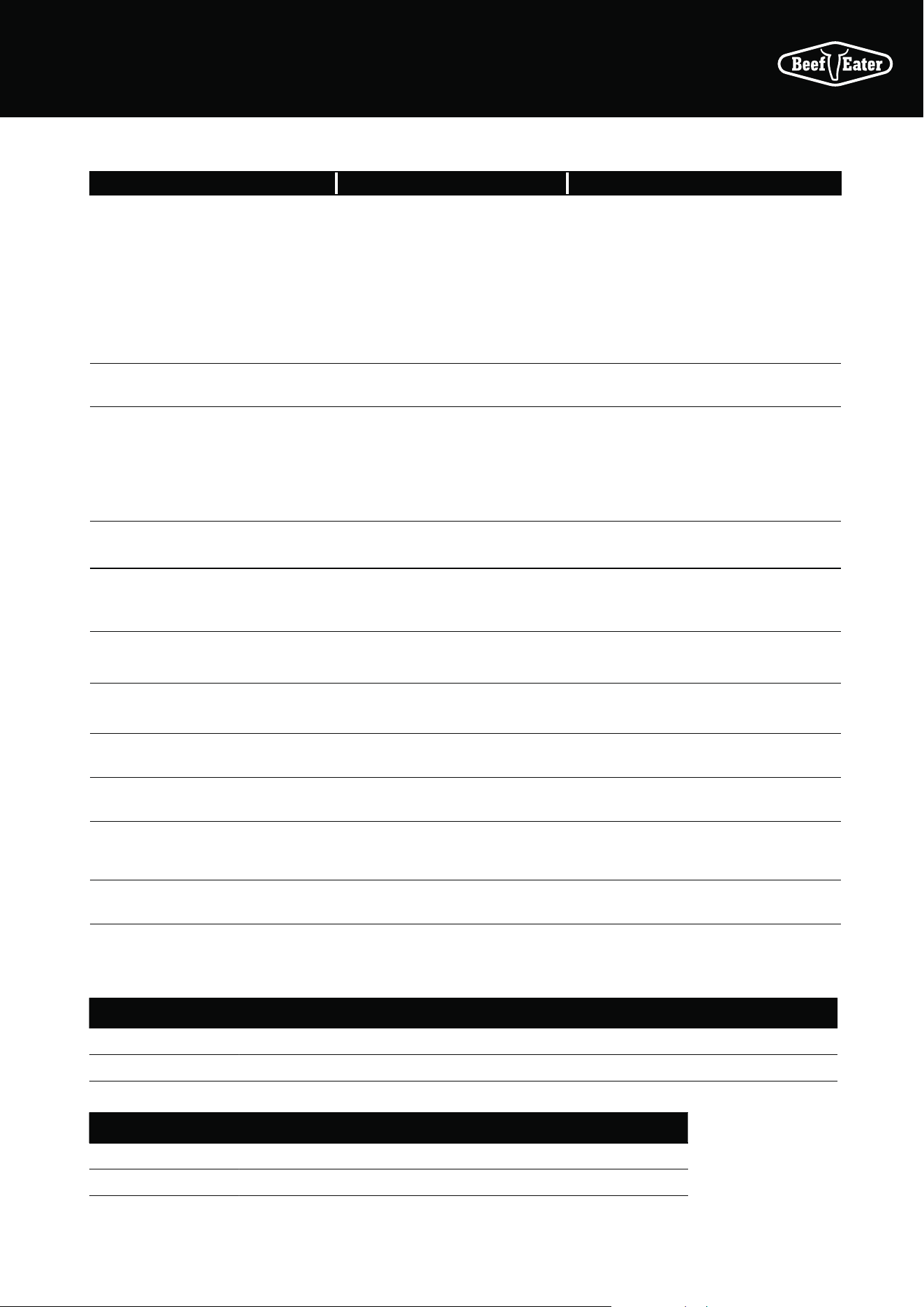
TYPE OF MEAT COOKING TEMPERATURE APPROXIMATE COOKING TIMES
Beef 180°C/355°F 45–55min per kg 20–25min per lb
Lamb 180°C/355°F 45–55min per kg 20–25min per lb
Pork 170°C/340°F 55–60min per kg 25–30min per lb
Veal 160°C/320°F 40–50min per kg 18–23min per lb
Poultry 180°C/355°F 40–50min per kg 18–23min per lb
Seafood 150°C/300°F 20–30min per kg 9–15min per lb
You may find it useful to purchase a meat thermometer to
help take the guess work out of cooking.
Meats such as beef, lamb, veal and pork should be about
70˚C/160˚F when medium. Chicken and turkey should be
85–90˚C/185–195˚F.
Most importantly, do not allow your barbecue to overheat.
Your hood is designed to keep the heat in, and also requires
constant monitoring.
Do not use more than 2 burners on high at any one time. As
a guide, for a 4 burner barbecue in moderate weather:
Two burners on low produces 150°C/300°F
Two burners on medium produces 195°C/385°F
Two burners on high produces 240°C/460°F
During cold or windy conditions, more heat is required.
Finally, resist the temptation to keep opening the hood while
cooking. This will help to maintain a constant temperature,
and minimise cooking time.
CAUTION
Do not allow your barbecue to
overheat, as this may damage
some components.
Overheating
zone is coloured
Red
71OPERATING INSTRUCTIONS
The cleaning and care instructions are essential for the
proper functioning and operation of your appliance over time.
Failure to adhere to these care instructions may affect your
ability to make a claim under the manufacturer’s warranty.
Cleaning Enamel burner box
Although porcelain enamel will keep its lustrous finish even
under adverse conditions, it still needs regular cleaning.
After the appliance has been used, wash down the surfaces
with hot soapy water. Caustic cleaners should be avoided.
For barbecues near the ocean or salt-water environment,
more frequent cleaning and servicing should be conducted.
Wash regularly, rinse and then dry before covering. (In a salt
water or marine environment, more rapid deterioration can
be expected which is not covered by warranty).
Cleaning Plates and Grills
Many food acids, marinades, juices and sauces contain
highly acidic elements that will slowly attack the surface of
the plates and grills if not removed after cooking.
• After use, remove all solid material from the cooking
surfaces using a brass bristle brush or plastic scourer.
Brushes specifically designed for this purpose can
be purchased from your BeefEater retailer. Wipe off
remaining residue with a paper towel
• Wash the surface of the grills with a soft sponge and
a solution of hot water and a mild dishwashing liquid.
Do not use highly caustic, harsh or abrasive chemical
cleaners to clean the cooking grills. Always check the
manufacturer’s recommendations for the cleaner prior
to use
• Coat the grills with a layer of cooking oil. This will help
protect the surfaces between uses
Cleaning the grease tray
Never remove the grease tray while the barbecue is hot.
Always remove and clean the grease tray after the unit has
cooled down.
Replace aluminium foil drip tray and clean grease tray at
regular intervals to prevent grease build-up. Otherwise, a
grease fire could result and void the barbecue warranty.
Cleaning the control panel and hood
Wash the surfaces of the control panel and hood with a soft
sponge and a solution of hot water and a mild dishwashing
liquid. Do not use highly caustic, harsh or abrasive chemical
cleaners or scouring pads as these will damage the surface
of the panels.
Cleaning the hood glass
Baked on fat on the inside of the hood glass can be removed
by using a razor blade scraper. It is best to
do this when the glass is still warm but not hot.
Finish cleaning with dishwashing detergent on a
damp cloth.
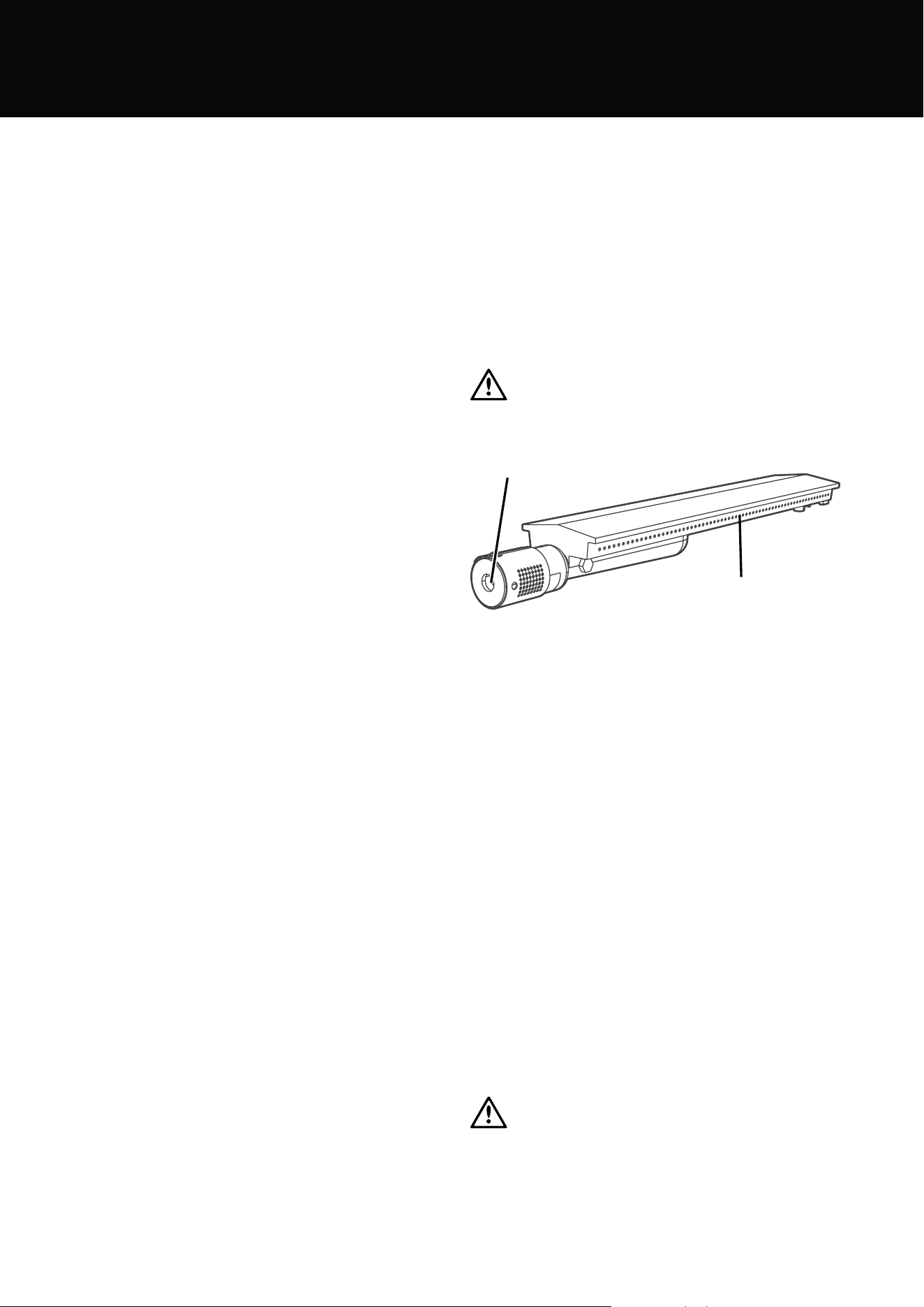
Cleaning the Burners
• Check main opening of burner regularly for insect nests
(eg. wasp, ants or spiders). Nests are dangerous and
must be cleaned out thoroughly.
• Remove burners periodically and scrub clean with soapy
water and a wire brush making sure that the ports are
free of obstructions.
Replace burners in the correct position and dry by lighting
each one to avoid subsequent corrosion.
CAUTION
A clogged burner can lead to a fire beneath the grill.
Main opening
Burner ports
Inspecting the hose and Regulator Assembly and Cylinder
• Inspect the hose and regulator assembly for abrasion,
aging or any damage that may result in a gas leak at
periodic intervals, at least once a year, and whenever
replacing a cylinder.
• Replace the assembly if necessary to ensure safe
operation
• After connecting the assembly to a cylinder always
carry out a leak check
• Only connect the appliance to cylinders that are
current according to the date marking on the cylinder.
Storing your Barbecue
When storing barbecue for extended periods, be certain all
controls and cylinder valves are turned off.
Gas cylinders must be stored outdoors, out of reach of
children and must not be stored in a building, garage or any
other enclosed area.
The barbecue should be covered when not in use.
A barbecue cover is available as an accessory.
The gas cylinder supply valve must be turned off when the
appliance is not in use.
WARNING
Note: For storage and cylinder exchange, disconnect hose
at the cylinder only, do not disconnect hose from appliance.
OPERATING INSTRUCTIONS
72 OPERATING INSTRUCTIONS
TROUBLESHOOTING
PROBLEM CAUSE CHECK
Barbecue will not light Ignition system not working Check to see visible spark at starter probe
- if no spark is present when control knob
is turned then the unit may need to
be serviced or replaced. Contact your
BeefEater dealer.
Check that there is a visible flame coming
from the pilot ignition tube.
Check that the pilot ignition tube is not
blocked by spider webs or insect nests.
Turning on gas control too quickly Allow at least 5 seconds for gas to flow
through burner before ignition.
No gas flow Check that valve on gas cylinder is turned
on.
Check that burner ports are free of
obstructions.
Check that all gas injectors are clean and
free of obstructions.
Burners not assembled correctly Check that burners are correctly positioned
in the barbecue frame.
Burner ports or throat blocked Check that the burner ports are not
blocked by spider webs or insect nests.
Clean out as required.
Barbecue lights but goes out
soon after starting
Fuel supply turned off Turn on gas valve at cylinder.
Gas cylinder low or empty Replace cylinder and carry out a leak check.
Kink in gas hose Check that the gas line is not kinked or
twisted.
Wind or breeze affecting operation Ensure that the appliance is located out of
the way of wind.
Burners will not cross light from one
to the other
Check that cross light channel is in place.
Check that burner ports are free of
obstructions.
Low flame level or low heat output Burners will not cross light Check you are running on correct gas
Check gas injector size is correct.
LPG BTU/hr MJ/hr kW g/hr
4 Burners 64,451 68 18.89 1,371
5 Burners 80,564 85 23.62 17,714
NG BTU/hr MJ/hr kW
4 Burners 64,451 68 18.89
5 Burners 80,564 85 23.62
Gas Consumption
73TROUBLESHOOTING

74
NOTES
NOTES
NOTES

75
This document sets out the terms and conditions of the product
warranties for BeefEater Appliances. It is an important document.
Please keep it with your proof of purchase documents in a safe place
for future reference should there be a manufacturing defect in your
Appliance. This warranty is in addition to other rights you may have
under the Australian Consumer Law.
1. In this warranty:
(a) ‘ACL’ or ‘Australian Consumer Law’ means Schedule 2 to the
Competition and Consumer Act 2010;
(b) ‘Appliance’ means any Electrolux product purchased by you and
accompanied by this document;
(c) ‘ASC’ means Electrolux’s authorised serviced centres;
(d) ‘BeefEater’ is the brand controlled by Electrolux Home Products Pty Ltd
of 163 O’Riordan Street, Mascot NSW 2020, ABN 51 004 762 341 in
respect of Appliances purchased in Australia and Electrolux (NZ) Limited
(collectively “Electrolux”) of 3-5 Niall Burgess Road, Mount Wellington, in
respect of Appliances purchased in New Zealand;
L º>HYYHU[`7LYPVK»TLHUZ[OLWLYPVKZWLJPÄLKPUJSH\ZLVM[OPZ
warranty;
(f) ‘you’ means the purchaser of the Appliance not having purchased the
Appliance for re-sale, and ‘your’ has a corresponding meaning.
2. Application: This warranty only applies to new Appliances, purchased
and used in Australia or New Zealand and is in addition to (and does not
exclude, restrict, or modify in any way) other rights and remedies under
a law to which the Appliances or services relate, including any non-
excludable statutory guarantees in Australia and New Zealand.
3. Warranty Period: Subject to these terms and conditions, this warranty
continues in Australia for a period of 24 months and in New Zealand
for a period of 24 months, following the date of original purchase of the
(WWSPHUJL:WLJPÄJJVTWVULU[ZHYL^HYYHU[LKHNHPUZ[THU\MHJ[\YPUN
defects in Australia and New Zealand for the periods listed below;
• Stainless steel box, plates and grills (excludes burners, gas valves
and ignitions) – Further 8 years
• Quartz stone & marine grade plywood carcasses – Further 3 years
4. Repair or replace warranty: During the Warranty Period, Electrolux
or its ASC will, at no extra charge if your Appliance is readily accessible
for service, without special equipment and subject to these terms and
conditions, repair or replace any parts which it considers to be defective.
Electrolux may, in its absolute discretion, choose whether the remedy
VќLYLKMVYH]HSPK^HYYHU[`JSHPTPZYLWHPYVYYLWSHJLTLU[,SLJ[YVS\_VYP[Z
ASC may use refurbished parts to repair your Appliance. You agree that
any replaced Appliances or parts become the property of Electrolux.
5. Travel and transportation costs: Subject to clause 7, Electrolux will
bear the reasonable cost of transportation, travel and delivery of the
Appliance to and from Electrolux or its ASC. Travel and transportation will
be arranged by Electrolux as part of any valid warranty claim.
6. Proof of purchase is required before you can make a claim under this
warranty.
7. Exclusions: You may not make a claim under this warranty unless the
defect claimed is due to faulty or defective parts or workmanship. This
warranty does not cover:
H SPNO[NSVILZIH[[LYPLZÄS[LYZVYZPTPSHYWLYPZOHISLWHY[Z"
(b) parts and Appliances not supplied by Electrolux;
J JVZTL[PJKHTHNL^OPJOKVLZUV[HќLJ[[OLVWLYH[PVUVM[OL
Appliance;
(d) damage to the Appliance caused by:
(i) negligence or accident;
(ii) misuse or abuse, including failure to properly maintain or service;
(iii) improper, negligent or faulty servicing or repair works done by
anyone other than an Electrolux authorised repairer or ASC;
(iv) normal wear and tear;
(v) power surges, electrical storm damage or incorrect power supply;
(vi) incomplete or improper installation;
(vii) incorrect, improper or inappropriate operation;
(viii) insect or vermin infestation;
(ix) failure to comply with any additional instructions supplied with
the Appliance;
In addition, Electrolux is not liable under this warranty if:
(a) the Appliance has been, or Electrolux reasonably believes that the
Appliance has been, used for purposes other than those for which
the Appliance was intended, including where the Appliance has
been used for any non-domestic purpose;
I [OL(WWSPHUJLPZTVKPÄLK^P[OV\[H\[OVYP[`MYVT,SLJ[YVS\_PU^YP[PUN"
(c) the Appliance’s serial number or warranty seal has been removed
or defaced.
8. How to claim under this warranty: To enquire about claiming under this
warranty, please follow these steps:
(a) carefully check the operating instructions, user manual and the
terms of this warranty;
(b) have the model and serial number of the Appliance available;
(c)
have the proof of purchase (e.g. an invoice) available;
(d) telephone the numbers shown below.
9. Australia: For Appliances and services provided by Electrolux in
Australia: Electrolux goods come with guarantees that cannot be
excluded under the Australian Consumer Law. You are entitled to a
replacement or refund for a major failure and for compensation for any
other reasonably foreseeable loss or damage. You are also entitled to
have the Appliance repaired or replaced if the Appliance fails to be of
acceptable quality and the failure does not amount to a major failure.
‘Acceptable quality’ and ‘major failure’ have the same meaning as
referred to in the ACL.
10. New Zealand: For Appliances and services provided by Electrolux
in New Zealand, the Appliances come with a guarantee by Electrolux
pursuant to the provisions of the Consumer Guarantees Act, the Sale of
Goods Act and the Fair Trading Act. Where the Appliance was purchased
in New Zealand for commercial purposes the Consumer Guarantee Act
does not apply.
*VUÄKLU[PHSP[`! You accept that if you make a warranty claim, Electrolux
and its agents including ASC may exchange information in relation to you
to enable Electrolux to meet its obligations under this warranty.
Warranty
FOR SALES IN AUSTRALIA AND NEW ZEALAND
APPLIANCE: BEEFEATER SIGNATURE BBQ, ALFRESCO KITCHEN
BSig_ODK_BBQ_Warr_Apr20
Important Notice
Before calling for service, please ensure that the steps listed in clause 8 above have been followed.
AUSTRALIA
FOR SERVICE
VY[VÄUK[OLHKKYLZZVM`V\YULHYLZ[
authorised service centre in Australia
PLEASE CALL 1300 307 939
For the cost of a local call
FOR SPARE PARTS
VY[VÄUK[OLHKKYLZZVM`V\YULHYLZ[
spare parts centre in Australia
PLEASE CALL 13 13 50
For the cost of a local call
NEW ZEALAND
FOR SERVICE
VY[VÄUK[OLHKKYLZZVM`V\YULHYLZ[
authorised service centre in New Zealand
PLEASE CALL 0800 10 66 10
FOR SPARE PARTS
VY[VÄUK[OLHKKYLZZVM`V\YULHYLZ[
spare parts centre in New Zealand
PLEASE CALL 0800 10 66 20
WARRANTY
WARRANTY

© 2022 Electrolux Home Products Pty Ltd.
ABN 51 004 762 341
B_MAN_7000_MOB_Apr22
Contact us if you need more help
AUSTRALIA
phone: 1300 307 939
email: customercare@beefeaterbbq.com
web: beefeaterbbq.com
NEW ZEALAND
phone: 0800 436 245
email: customercare@electrolux.co.nz
web: beefeaterbbq.com