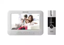

Video Door Phone
User Manual

Video Door Phone User Manual
i
Legal Information
© 2021 Hangzhou Hikvision Digital Technology Co., Ltd. All rights reserved.
This user manual is intended for users of the models below:
Product
Model
Video Door Phone
DS-KIS203T
Door Station
DS-KB2421T-IM
Indoor Station
DS-KH2220
About this Manual
The Manual includes instructions for using and managing the Product. Pictures, charts, images and
all other information hereinafter are for description and explanation only. The information
contained in the Manual is subject to change, without notice, due to firmware updates or other
reasons. Please find the latest version of this Manual at the Hikvision website
(https://www.hikvision.com/).
Please use this Manual with the guidance and assistance of professionals trained in supporting the
Product.
Trademarks
and other Hikvision's trademarks and logos are the properties of
Hikvision in various jurisdictions.
Other trademarks and logos mentioned are the properties of their respective owners.
Disclaimer
TO THE MAXIMUM EXTENT PERMITTED BY APPLICABLE LAW, THIS MANUAL AND THE PRODUCT
DESCRIBED, WITH ITS HARDWARE, SOFTWARE AND FIRMWARE, ARE PROVIDED "AS IS" AND
"WITH ALL FAULTS AND ERRORS". HIKVISION MAKES NO WARRANTIES, EXPRESS OR IMPLIED,
INCLUDING WITHOUT LIMITATION, MERCHANTABILITY, SATISFACTORY QUALITY, OR FITNESS FOR
A PARTICULAR PURPOSE. THE USE OF THE PRODUCT BY YOU IS AT YOUR OWN RISK. IN NO EVENT
WILL HIKVISION BE LIABLE TO YOU FOR ANY SPECIAL, CONSEQUENTIAL, INCIDENTAL, OR INDIRECT
DAMAGES, INCLUDING, AMONG OTHERS, DAMAGES FOR LOSS OF BUSINESS PROFITS, BUSINESS
INTERRUPTION, OR LOSS OF DATA, CORRUPTION OF SYSTEMS, OR LOSS OF DOCUMENTATION,
WHETHER BASED ON BREACH OF CONTRACT, TORT (INCLUDING NEGLIGENCE), PRODUCT LIABILITY,
OR OTHERWISE, IN CONNECTION WITH THE USE OF THE PRODUCT, EVEN IF HIKVISION HAS BEEN
ADVISED OF THE POSSIBILITY OF SUCH DAMAGES OR LOSS.
YOU ACKNOWLEDGE THAT THE NATURE OF THE INTERNET PROVIDES FOR INHERENT SECURITY
RISKS, AND HIKVISION SHALL NOT TAKE ANY RESPONSIBILITIES FOR ABNORMAL OPERATION,
PRIVACY LEAKAGE OR OTHER DAMAGES RESULTING FROM CYBER-ATTACK, HACKER ATTACK,
VIRUS INFECTION, OR OTHER INTERNET SECURITY RISKS; HOWEVER, HIKVISION WILL PROVIDE
TIMELY TECHNICAL SUPPORT IF REQUIRED.

Video Door Phone User Manual
ii
YOU AGREE TO USE THIS PRODUCT IN COMPLIANCE WITH ALL APPLICABLE LAWS, AND YOU ARE
SOLELY RESPONSIBLE FOR ENSURING THAT YOUR USE CONFORMS TO THE APPLICABLE LAW.
ESPECIALLY, YOU ARE RESPONSIBLE, FOR USING THIS PRODUCT IN A MANNER THAT DOES NOT
INFRINGE ON THE RIGHTS OF THIRD PARTIES, INCLUDING WITHOUT LIMITATION, RIGHTS OF
PUBLICITY, INTELLECTUAL PROPERTY RIGHTS, OR DATA PROTECTION AND OTHER PRIVACY RIGHTS.
YOU SHALL NOT USE THIS PRODUCT FOR ANY PROHIBITED END-USES, INCLUDING THE
DEVELOPMENT OR PRODUCTION OF WEAPONS OF MASS DESTRUCTION, THE DEVELOPMENT OR
PRODUCTION OF CHEMICAL OR BIOLOGICAL WEAPONS, ANY ACTIVITIES IN THE CONTEXT RELATED
TO ANY NUCLEAR EXPLOSIVE OR UNSAFE NUCLEAR FUEL-CYCLE, OR IN SUPPORT OF HUMAN
RIGHTS ABUSES.
IN THE EVENT OF ANY CONFLICTS BETWEEN THIS MANUAL AND THE APPLICABLE LAW, THE LATER
PREVAILS.
Data Protection
During the use of device, personal data will be collected, stored and processed. To protect data,
the development of Hikvision devices incorporates privacy by design principles. For example, for
device with facial recognition features, biometrics data is stored in your device with encryption
method; for fingerprint device, only fingerprint template will be saved, which is impossible to
reconstruct a fingerprint image.
As data controller, you are advised to collect, store, process and transfer data in accordance with
the applicable data protection laws and regulations, including without limitation, conducting
security controls to safeguard personal data, such as, implementing reasonable administrative and
physical security controls, conduct periodic reviews and assessments of the effectiveness of your
security controls.
Video Door Phone User Manual
iii
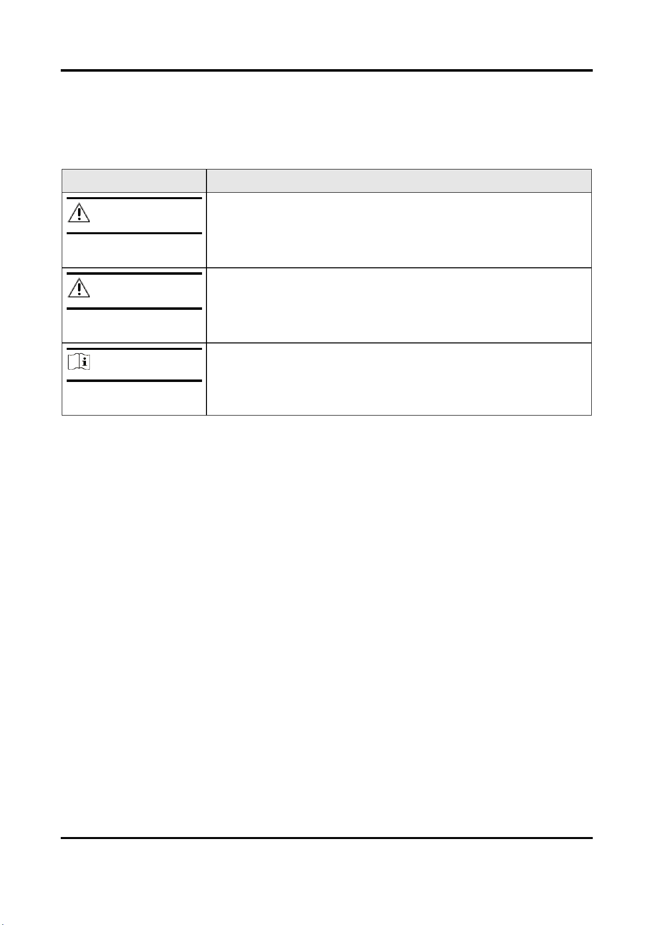
Symbol Conventions
The symbols that may be found in this document are defined as follows.
Symbol
Description
Danger
Indicates a hazardous situation which, if not avoided, will or could
result in death or serious injury.
Caution
Indicates a potentially hazardous situation which, if not avoided,
could result in equipment damage, data loss, performance
degradation, or unexpected results.
Note
Provides additional information to emphasize or supplement
important points of the main text.
Video Door Phone User Manual
iv
Regulatory Information
FCC Information
Please take attention that changes or modification not expressly approved by the party
responsible for compliance could void the user's authority to operate the equipment.
FCC compliance: This equipment has been tested and found to comply with the limits for a Class B
digital device, pursuant to part 15 of the FCC Rules. These limits are designed to provide
reasonable protection against harmful interference in a residential installation. This equipment
generates, uses and can radiate radio frequency energy and, if not installed and used in
accordance with the instructions, may cause harmful interference to radio communications.
However, there is no guarantee that interference will not occur in a particular installation. If this
equipment does cause harmful interference to radio or television reception, which can be
determined by turning the equipment off and on, the user is encouraged to try to correct the
interference by one or more of the following measures:
—Reorient or relocate the receiving antenna.
—Increase the separation between the equipment and receiver.
—Connect the equipment into an outlet on a circuit different from that to which the receiver is
connected.
—Consult the dealer or an experienced radio/TV technician for help
This equipment should be installed and operated with a minimum distance 20cm between the
radiator and your body.
FCC Conditions
This device complies with part 15 of the FCC Rules. Operation is subject to the following two
conditions:
1. This device may not cause harmful interference.
2. This device must accept any interference received, including interference that may cause
undesired operation.
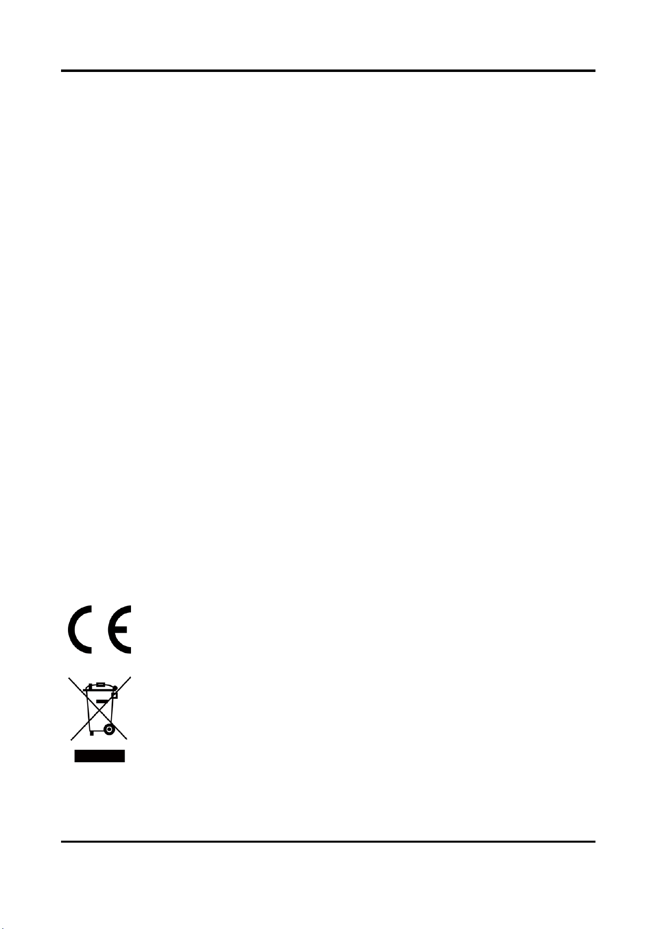
EU Conformity Statement
This product and - if applicable - the supplied accessories too are marked with "CE"
and comply therefore with the applicable harmonized European standards listed
under the EMC Directive 2014/30/EU, RE Directive 2014/53/EU,the RoHS Directive
2011/65/EU
2012/19/EU (WEEE directive): Products marked with this symbol cannot be
disposed of as unsorted municipal waste in the European Union. For proper
recycling, return this product to your local supplier upon the purchase of equivalent
new equipment, or dispose of it at designated collection points. For more
information see: www.recyclethis.info

Video Door Phone User Manual
v
2006/66/EC (battery directive): This product contains a battery that cannot be
disposed of as unsorted municipal waste in the European Union. See the product
documentation for specific battery information. The battery is marked with this
symbol, which may include lettering to indicate cadmium (Cd), lead (Pb), or
mercury (Hg). For proper recycling, return the battery to your supplier or to a
designated collection point. For more information see:www.recyclethis.info
Industry Canada ICES-003 Compliance
This device meets the CAN ICES-3 (B)/NMB-3(B) standards requirements.
1. This device complies with Industry Canada licence-exempt RSS standard(s). Operation is
subject to the following two conditions: this device may not cause interference, and
2. this device must accept any interference, including interference that may cause undesired
operation of the device.
1. Le présent appareil est conforme aux CNR d'Industrie Canada applicables aux appareils
radioexempts de licence. L'exploitation est autorisée aux deux conditions suivantes : l'appareil
ne doit pas produire de brouillage, et
2. l'utilisateur de l'appareil doit accepter tout brouillage radioélectrique subi, même si le
brouillage est susceptible d'en compromettre le fonctionnement.
Under Industry Canada regulations, this radio transmitter may only operate using an antenna of a
type and maximum (or lesser) gain approved for the transmitter by Industry Canada. To reduce
potential radio interference to other users, the antenna type and its gain should be so chosen that
the equivalent isotropically radiated power (e.i.r.p.) is not more than that necessary for successful
communication.
Conformément à la réglementation d'Industrie Canada, le présent émetteur radio peut
fonctionner avec une antenne d'un type et d'un gain maximal (ou inférieur) approuvé pour
l'émetteur par Industrie Canada. Dans le but de réduire les risques de brouillage radioélectrique à
l'intention des autres utilisateurs, il faut choisir le type d'antenne et son gain de sorte que la
puissance isotrope rayonnée équivalente (p.i.r.e.) ne dépasse pas l'intensité nécessaire à
l'établissement d'une communication satisfaisante.
This equipment should be installed and operated with a minimum distance 20cm between the
radiator and your body.
Cet équipement doit être installé et utilisé à une distance minimale de 20 cm entre le radiateur et
votre corps.

Video Door Phone User Manual
vi
Contents
Chapter 1 Introduction ............................................................................................................... 1
1.1
Overview .............................................................................................................................. 1
1.2 Features ................................................................................................................................. 1
Chapter 2 Appearance Description ............................................................................................. 2
2.1 Indoor Station ........................................................................................................................ 2
2.2 Door Station ........................................................................................................................... 3
Chapter 3 Terminals and Wirings ................................................................................................ 4
3.1 Terminals and Interfaces ....................................................................................................... 4
3.1.1 Terminals of Indoor Station ....................................................................................... 4
3.1.2 Terminals of Door Station .......................................................................................... 4
3.2 Wiring Description ................................................................................................................. 5
3.2.1 Wiring 1 (1 Door Station and 1 Indoor Station) ........................................................ 7
3.2.2 Wiring 2 (1 Door Station and 3 Indoor Stations) ....................................................... 8
3.2.3 Wiring 3 (2 Door Stations and 3 Indoor Stations) ..................................................... 9
Chapter 4 Installation ............................................................................................................... 10
4.1 Indoor Station Installation .................................................................................................. 10
4.2 Door Station Installation ..................................................................................................... 11
Chapter 5 Local Operation ........................................................................................................ 13
5.1 Door Station Local Operation ............................................................................................. 13
5.2 Indoor Station Local Operation........................................................................................... 13
A. Appendix ............................................................................................................................. 14
Video Door Phone User Manual
1
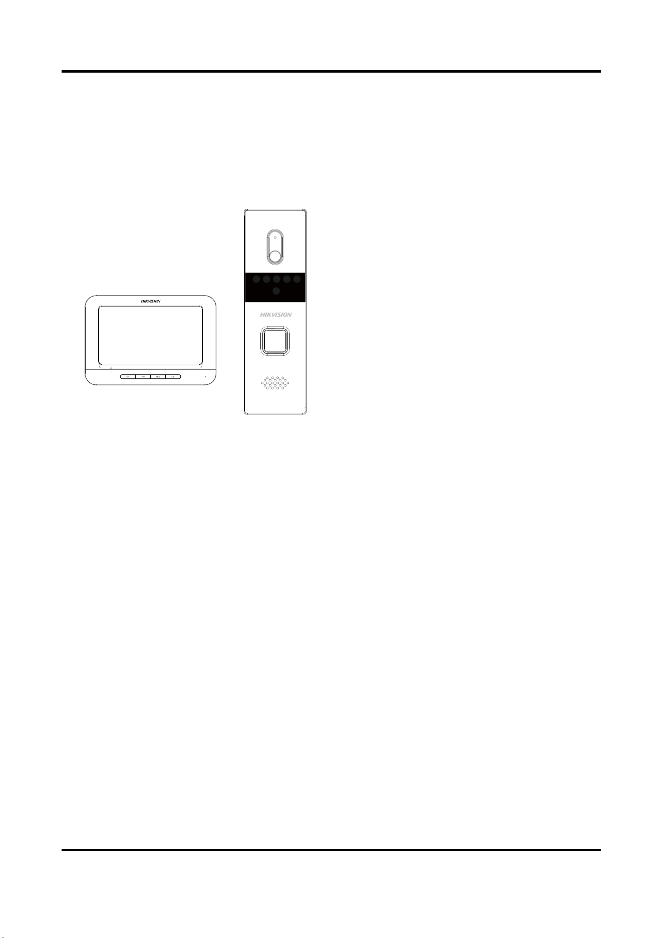
Chapter 1 Introduction
1.1 Overview
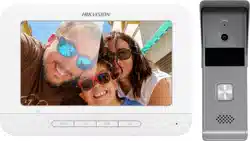
The video door phone is composed of a
four-wire indoor station and a four-wire
door station. Featuring in the convenient
installation and easy operation, it is mainly
applied in the buildings for improving the
living security.
1.2 Features
Indoor Station Features
● Hands-free video intercom communication
● Supports three indoor stations simultaneously in the intercom system
● Supports monitoring the door station and the external analog camera
● Remote unlocking
● Convenient installation and easy operation
Door Station Features
● Hands-free video intercom communication
● Supports two door stations simultaneously in the intercom system
● Self-adaptive IR supplement (with photoresistor)
● One-touch calling
● Camera with 1920 x 1080 @ 25 fps
● Unlock controlling
● Anti-oxidant aluminium alloy
● Convenient installation and easy operation
Video Door Phone User Manual
2
Chapter 2 Appearance Description
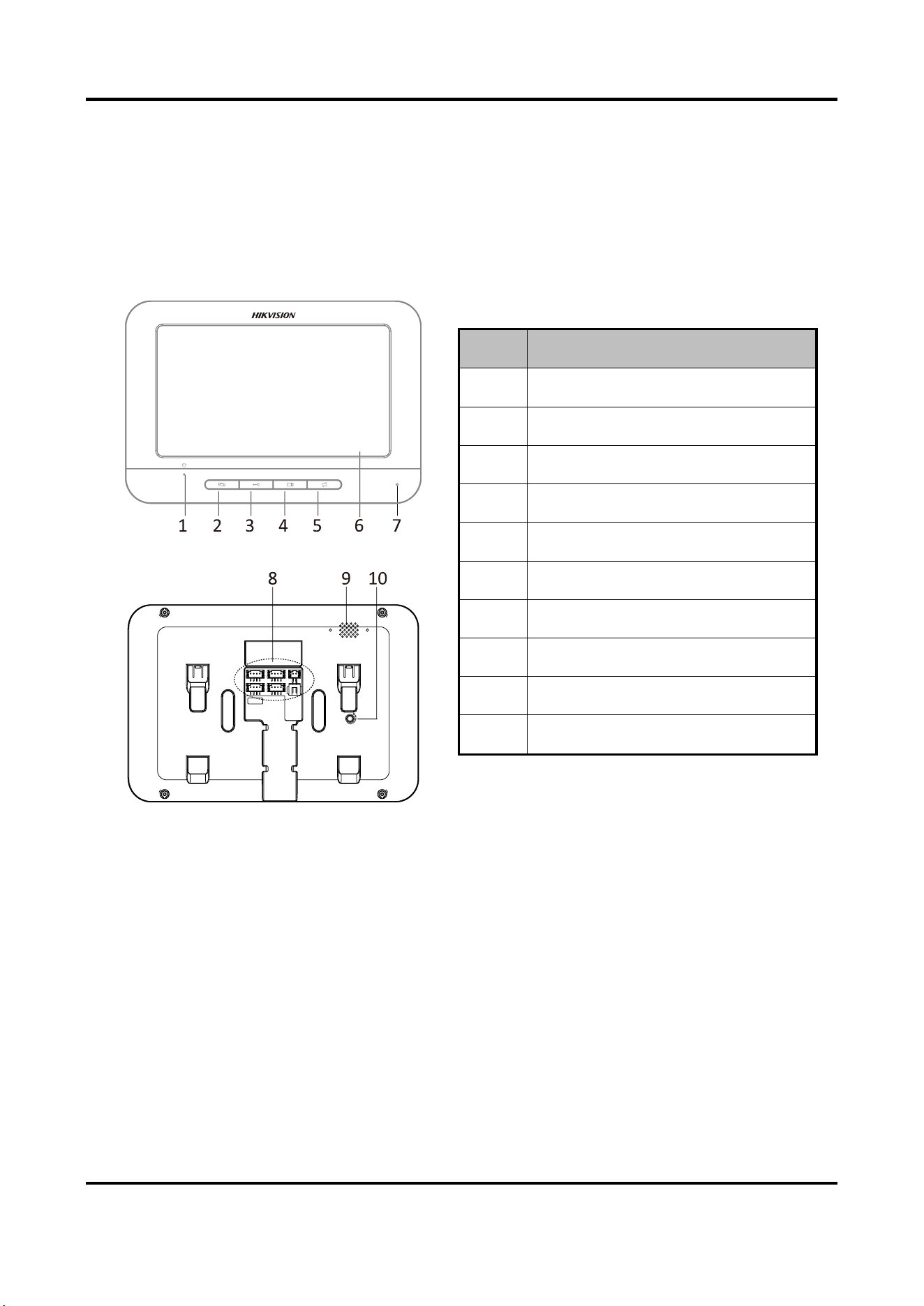
2.1 Indoor Station
Figure 2-1 Indoor Station Appearance
Table 2-1 Components Description
No.
Description
1
Power Supply Indicator
2
Call Accept/Decline Key
3
Unlock Key
4
Live View Key
5
Switch Key
6
LCD Screen
7
Microphone
8
Terminals and Interfaces
9
Loudspeaker
10
Volume Control Knob
Video Door Phone User Manual
3
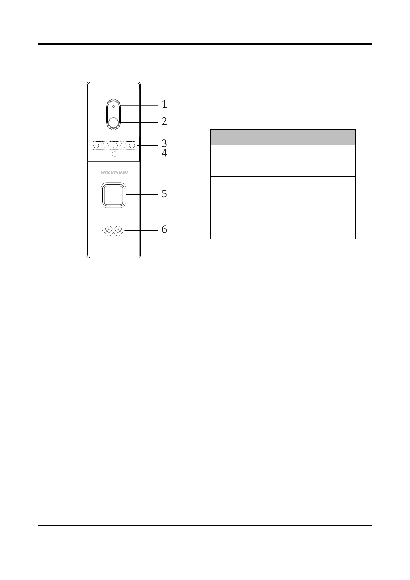
2.2 Door Station
Figure 2-2 Door Station Appearance
Table 2-2 Components Description
No.
Description
1
Microphone
2
Built-in Camera
3
IR Supplement Lights
4
Photoresistor
5
Call Button
6
Loudspeaker
Video Door Phone User Manual
4
Chapter 3 Terminals and Wirings
3.1 Terminals and Interfaces
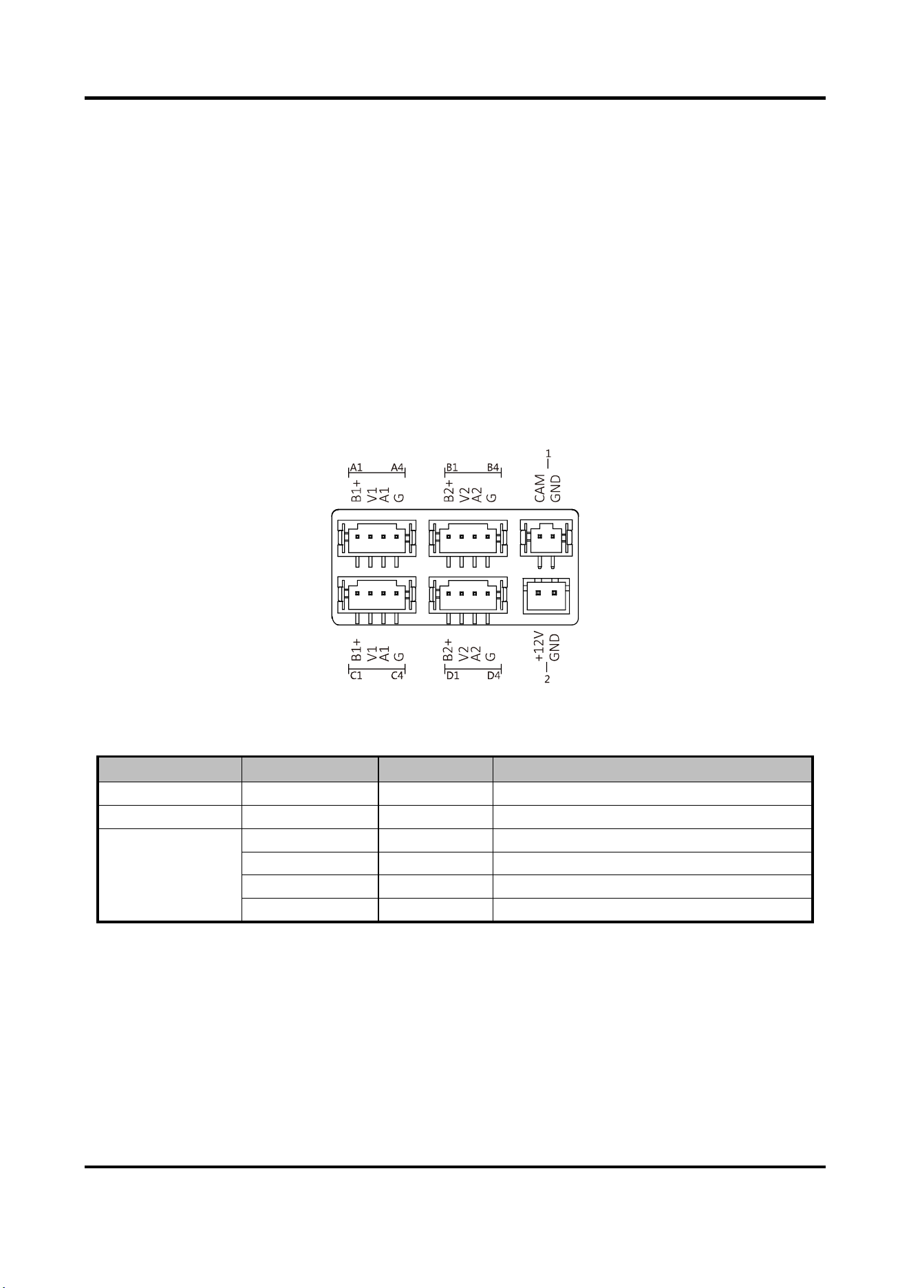
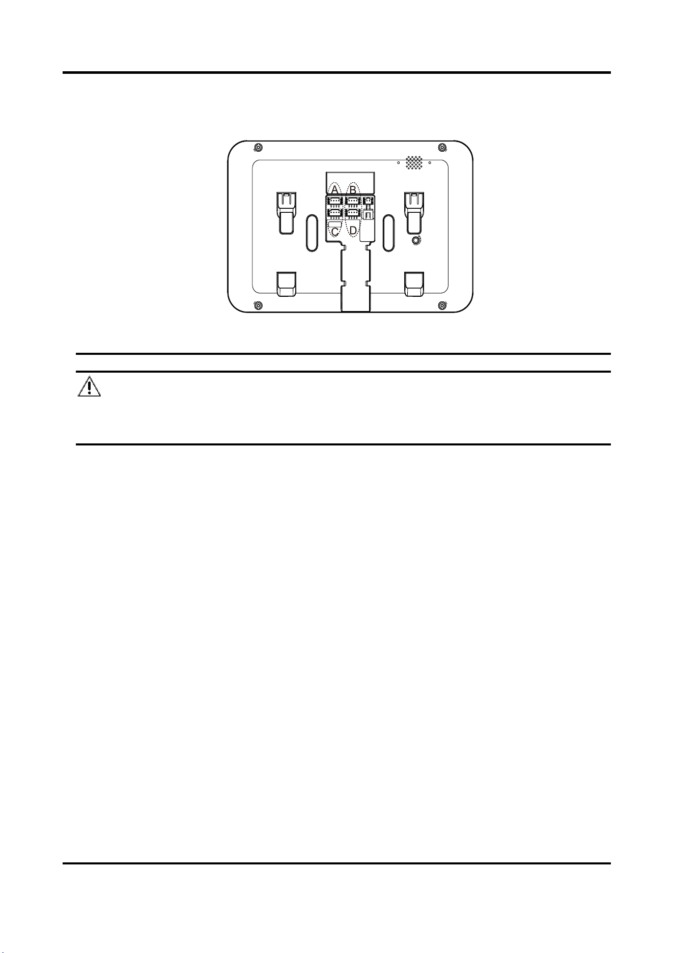
3.1.1 Terminals of Indoor Station
On the rear panel of the indoor station, there are 4 groups of four-wire terminals for connecting
indoor station or door station, 1 terminal for accessing the camera, and 1 terminal for power
supply.
Figure 3-1 Terminals of Indoor Station
Table 3-1 Descriptions of Terminals (Indoor Station)
Name
No.
Interface
Description
Camera
1
CAM
Analog Camera Access
Power Supply
2
12 VDC
12 VDC Power Supply Input
Four-Wire
Interface
A1/B1/C1/D1
B1+/B2+
Power Supply for Door Station
A2/B2/C2/D2
V1/V2
Video Input
A3/B3/C3/D3
A1/A2
Audio Input/Output
A4/B4/C4/D4
G
Grounding Signal
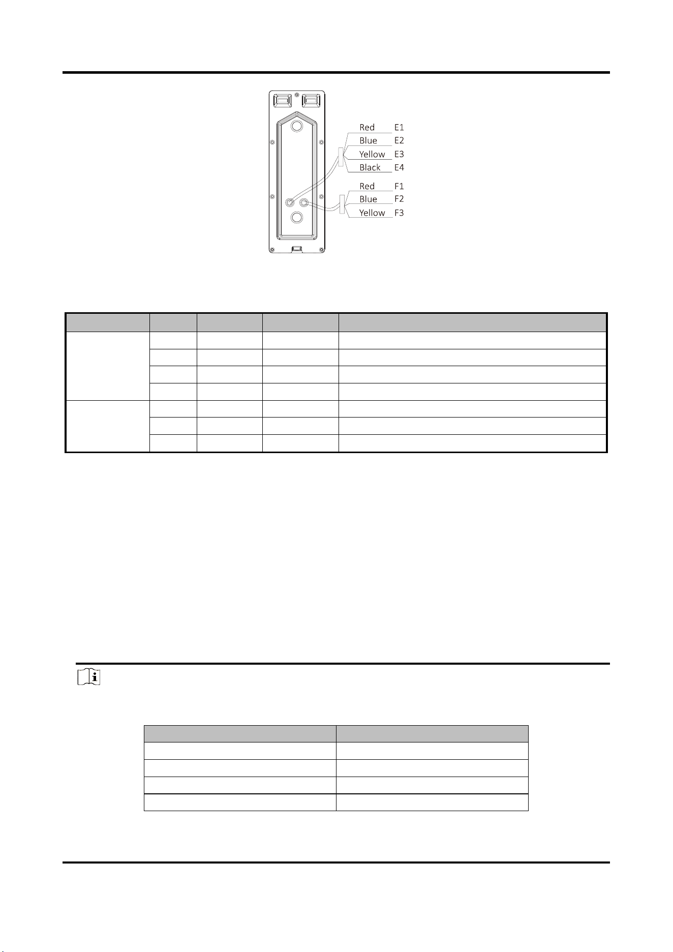
3.1.2 Terminals of Door Station
On the rear panel of the door station, there are 2 wire groups. 1 wire group is used to connect the
indoor station, and another wire group is used to connect the lock.
Video Door Phone User Manual
5
Figure 3-2 Wire of Door Station
Table 3-2 Descriptions of Terminals and Interfaces (Door Station)
Name
No.
Color
Interface
Description
Wire Group
(Four-Wire)
E1
Red
5V
Power Supply (from Indoor Station)
E2
Blue
CVBS
Video Output
E3
Yellow
AUIDO
Audio Input/Output
E4
Black
GND
Grounding Signal
Wire Group
(Lock)
F1
Red
NO
Door Lock Relay Output/Normally Open
F2
Blue
COM
Door Lock Relay Output/Common
F3
Yellow
NC
Door Lock Relay Output/Normally Closed
3.2 Wiring Description
Purpose:
The four-wire indoor station and the four-wire door station are 2 basic but major components in a
four-wire video intercom system. As for extended components, the analog camera and the electric
bolt can be connected to the indoor station and the door station respectively in a four-wire video
intercom system.
Up to 2 door stations are supported simultaneously in the intercom system.
Up to 3 indoor stations are supported simultaneously in the intercom system.
Here take 3 wirings as example.
Note
● According to different transmission distances among door stations and indoor stations,
different RVV4 cable specifications are demanded.
Transmission Distance (TD)
RVV4 Cable Specification
TD ≤ 10 m
RVV4 * 0.2 mm ^2
10 m < TD ≤ 30 m
RVV4 * 0.5 mm ^2
30 m < TD ≤ 50 m
RVV4 * 0.75 mm ^2
50 m < TD ≤ 100 m
RVV4 * 1.5 mm ^2
Video Door Phone User Manual
6
● On the rear panel of the indoor station, four-wire interface A and four-wire interface C
compose a cascading group; and four-wire interface B and four-wire interface C compose a
cascading group.
● The communication between A and B/D cannot be realized.
● The communication between C and B/D cannot be realized.
Caution
Do not connect the power wire of the four-core cable to the V pin (video wire) or A pin (audio
wire) of the four-wire interface.
Video Door Phone User Manual
7
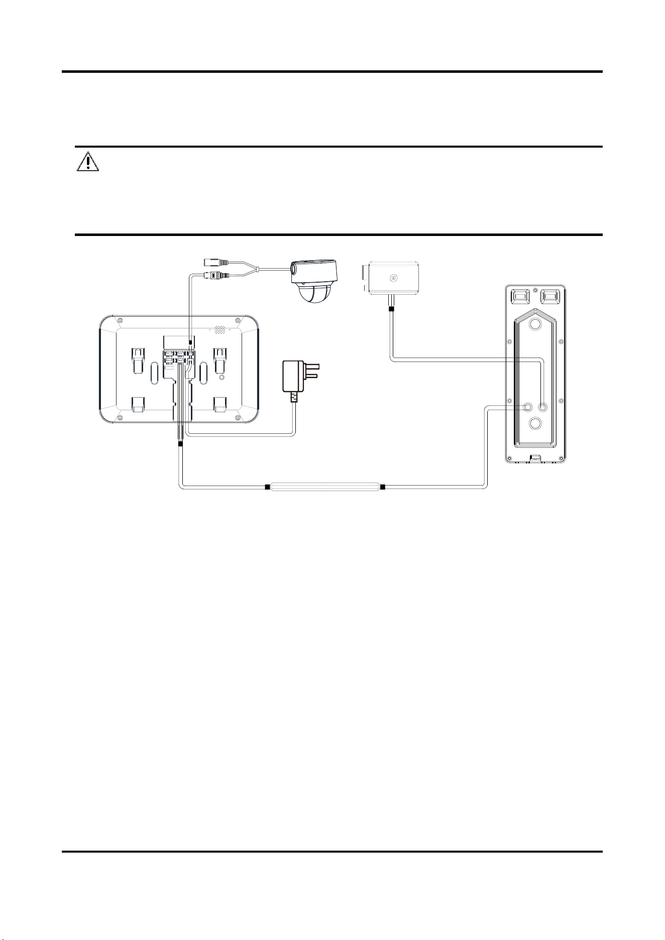
3.2.1 Wiring 1 (1 Door Station and 1 Indoor Station)
Caution
● Do not pull power cables on the rear panel of the door station hard to avoid the
disconnection of power cables.
● Use the insulated tape to tape the bare wires, so as to avoid the short circuit.
Indoor Station
Analog Camera Electric Bolt
Door Station
Red —— NO
Blue —— COM
Yellow —— NC
Red —— Wire for power supply
Blue —— Wire for video output
Yellow —— Wire for audio input/output
Black —— Wire for grounding
B+ —— Wire for power supply
V —— Wire for video input
A —— Wire for audio input
G —— Wire for grounding
Figure 3-3 Wiring 1 (1 Door Station and 1 Indoor Station)
Video Door Phone User Manual
8
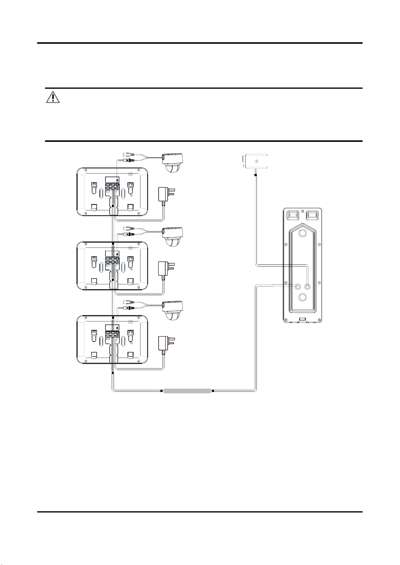
3.2.2 Wiring 2 (1 Door Station and 3 Indoor Stations)
Caution
● Do not pull power cables on the rear panel of the door station hard to avoid the
disconnection of power cables.
● Use the insulated tape to tape the bare wires, so as to avoid the short circuit.
Indoor
Station 1
B+ —— Wire for power supply
V —— Wire for video input
A —— Wire for audio input
G —— Wire for grounding
Analog Camera 1
Indoor
Station 2
Analog Camera 2
Indoor
Station 3
Analog Camera 3
Door
Station
Electric Bolt
Red —— Wire for power supply
Blue —— Wire for video output
Yellow —— Wire for audio input/output
Black —— Wire for grounding
Red —— NO
Blue —— COM
Yellow —— NC
Figure 3-4 Wiring 2 (1 Door Station and 3 Indoor Stations)
Video Door Phone User Manual
9
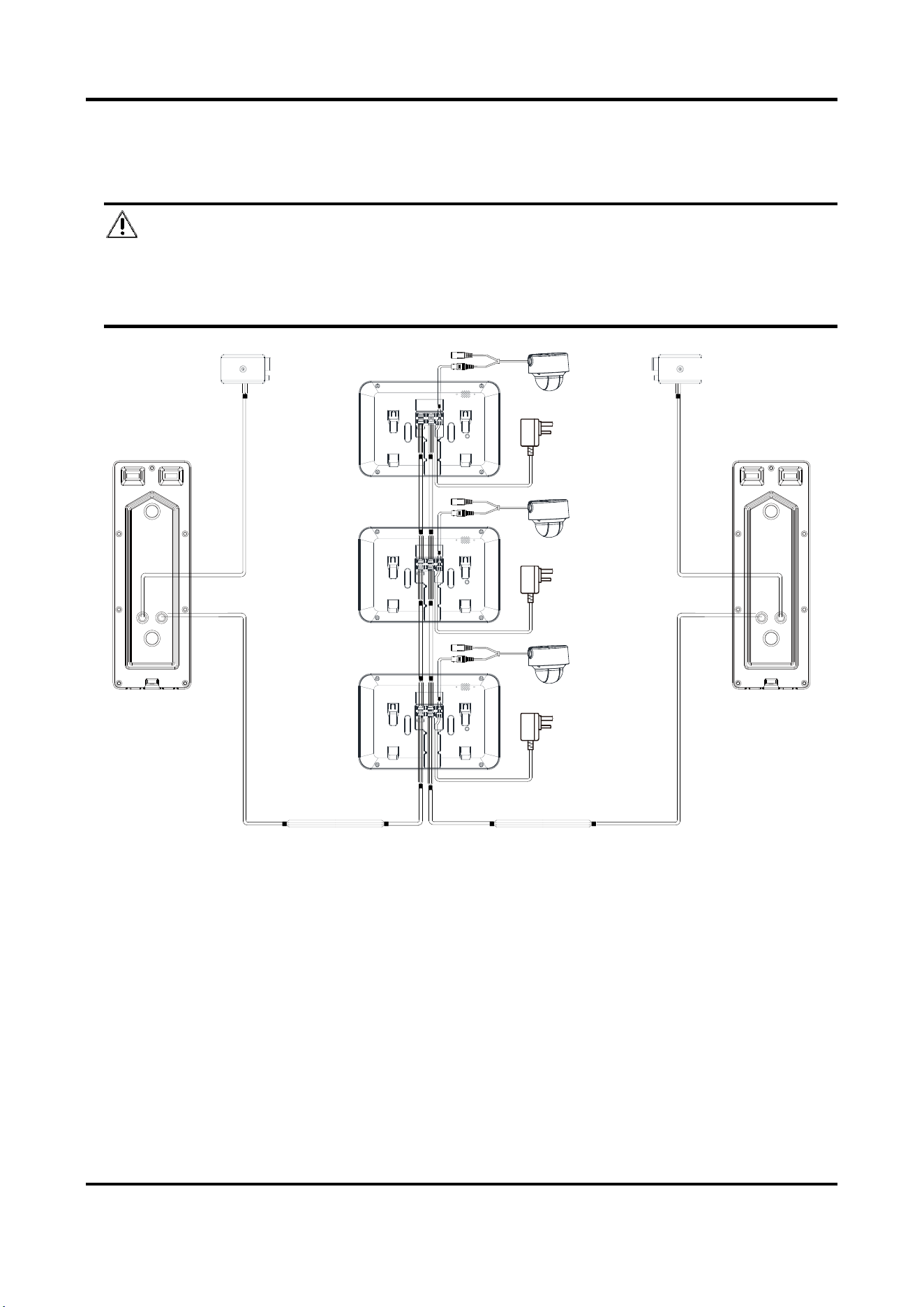
3.2.3 Wiring 3 (2 Door Stations and 3 Indoor Stations)
Caution
● Do not pull power cables on the rear panel of the door station hard to avoid the
disconnection of power cables.
● Use the insulated tape to tape the bare wires, so as to avoid the short circuit.
Indoor
Station 1
Analog Camera 1
Indoor
Station 2
Analog Camera 2
B+ —— Wire for power supply
V —— Wire for video input
A —— Wire for audio input
G —— Wire for grounding
Indoor
Station 3
Analog Camera 3
Door Station 2
Electric Bolt
Red —— Wire for power supply
Blue —— Wire for video output
Yellow —— Wire for audio input/output
Black —— Wire for grounding
Red —— NO
Blue —— COM
Yellow —— NC
Door Station 1
Electric Bolt
Red —— NO
Blue —— COM
Yellow —— NC
Figure 3-5 Wiring 3 (2 Door Stations and 3 Indoor Stations)
Video Door Phone User Manual
10
Chapter 4 Installation
Before you start:
● Make sure the device in the package is in good condition and all the assembly parts are
included.
● The power supply the indoor station supports is 12 VDC. Please make sure your power supply
matches your indoor station.
● Make sure all the related equipment is power-off during the installation.
● Check the specification of the product for the installation environment.
4.1 Indoor Station Installation
The indoor station supports the wall mounting, including the wall mounting with the junction box,
and the wall mounting without the junction box.
For the wall mounting with junction box, the wall mounting plate and the junction box are
required. And for the wall mounting without junction box, only the wall mounting plate is
required.
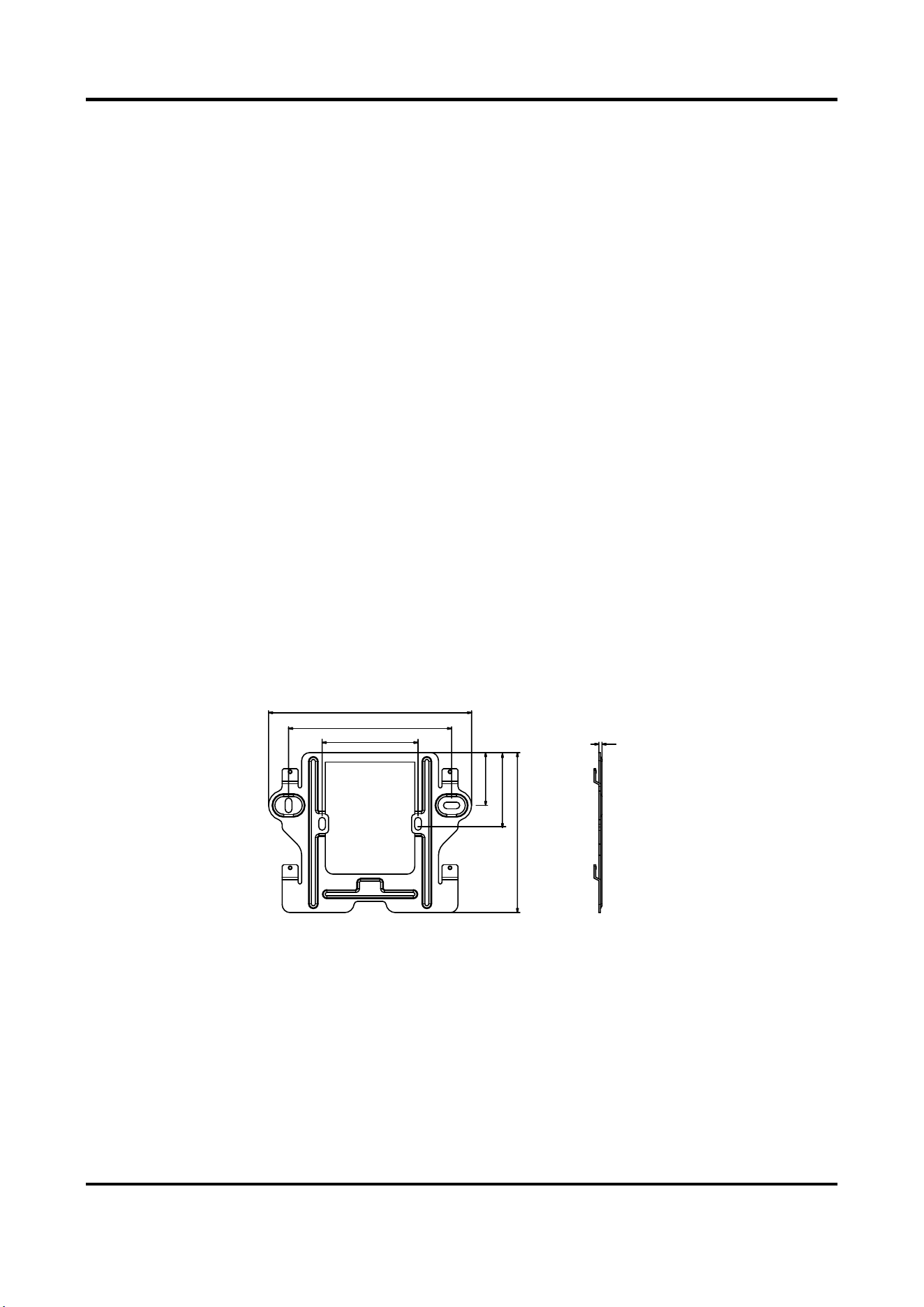
(Optional) The dimension of the junction box is 75 mm (width) x 75 mm (length) x 50 mm (depth).
The dimension of the wall mounting plate is shown below.
Wall Mounting Plate (Indoor Station)
127 mm
102 mm
60 mm
33 mm
46.4 mm
100 mm
2 mm
Figure 4-1 Wall Mounting Plate
Wall Mounting (Indoor Station)
You can follow the following steps to install the indoor station.
Here we take the wall mounting with the junction box as example.
Steps:
1. Insert the junction box to the hole chiseled on the wall.
Video Door Phone User Manual
11
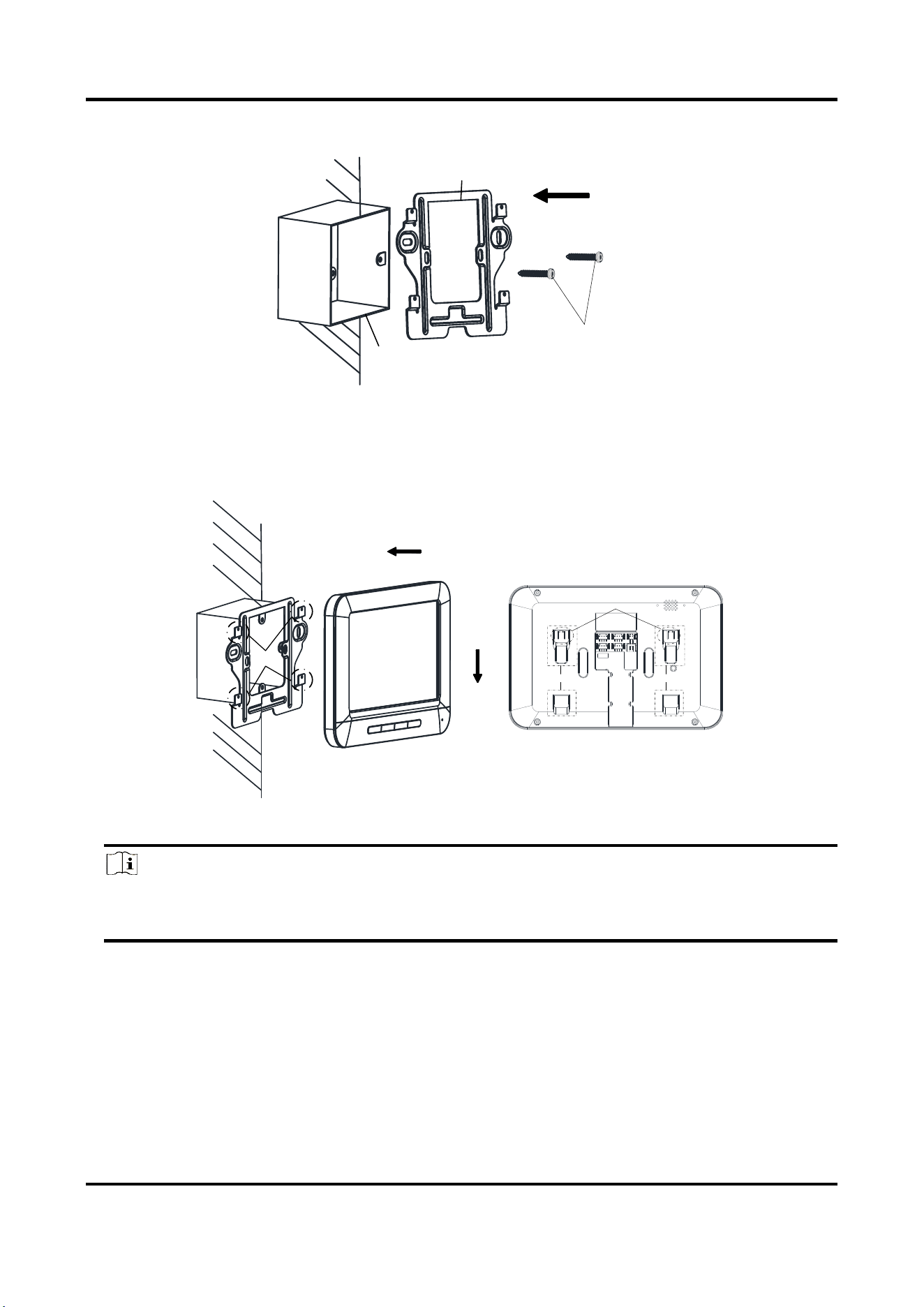
2. Fix the wall mounting plate to the junction box with 2 screws.
Screws
Wall Mounting Plate
Junction
Box
Figure 4-2 Installing the Plate
3. Hook the indoor station to the wall mounting plate tightly by inserting the plate hooks into the
slots on the rear panel of the indoor station, during which the lock catch will be locked
automatically.
Hooks
Slot Slot
Lock Catch
Figure 4-3 Hooking the Indoor Station to the Plate
Note
For the installation without the junction box, you should fix the wall mounting plate to the
wall with 2 expansion screws first, and then hook the indoor station.
4.2 Door Station Installation
Accessoris (Door Station)
To install the door station, the wall mounting shield and the wall mounting plate are required.
Video Door Phone User Manual
12
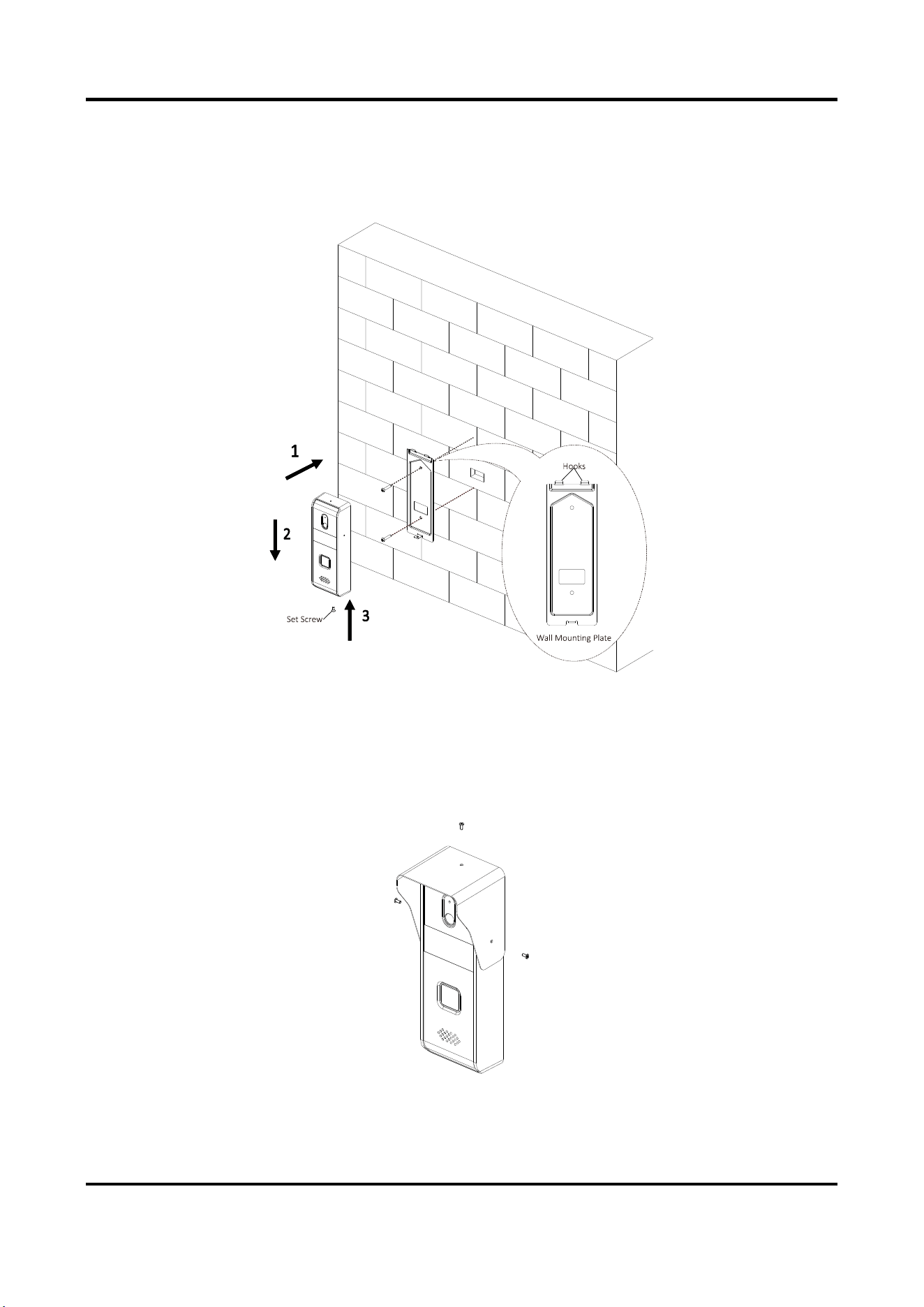
Wall Mounting (Door Station)
You can follow the following steps to install the door station.
Steps:
Figure 4-4 Install the Door Station
1. Fix the wall mounting plate to the wall with 2 screws.
2. Hook the door station to the shield tightly by inserting the hooks of shield panel into the slots
on the rear panel of the door station.
3. Secure the door station with the mounting shield with the set screw.
4. Use 3 screws to secure the wall mounting shield with the door station.
Figure 4-5 Secure Wall Mounting Shield
Video Door Phone User Manual
13
Chapter 5 Local Operation
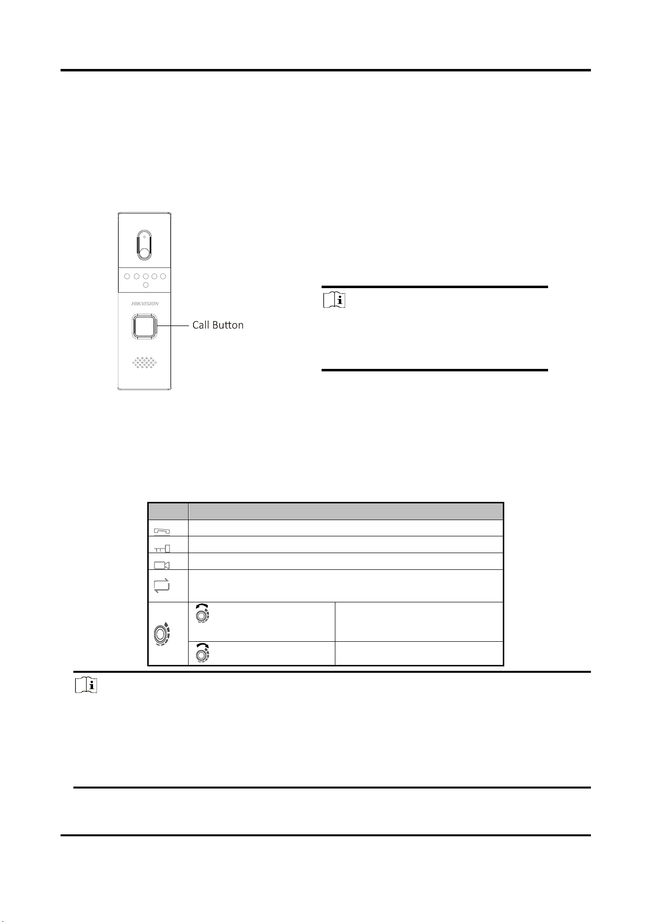
5.1 Door Station Local Operation
Figure 5-1 Call Button of Door Station
Steps:
Press the call button to call the resident.
Note
When press the call button to call the
resident, the maximum ring duration of
the indoor station is 30s.
5.2 Indoor Station Local Operation
Table 5-1 Indoor Station Local Operation Description
Keys
Description
Accept or decline the incoming call.
Unlock the door.
Open or close the live view.
Switch the live view among the first door station, the
second door station, and the analog camera.
Counterclockwise
rotation
Increase the volume.
Clockwise rotation
Decrease the volume.
Note
● The maximum live view duration is 60s; and the maximum speaking duration is 60s.
● During the ring duration, speaking duration, or live view duration, the resident can unlock the
door. The unlocking status can maintain 5 seconds after pressing the Unlock key.
● To achieve the optimal pickup effect, the recommended distance range between the speaker
and the microphone of the indoor station or the door station is 30 to 40 cm.

Video Door Phone User Manual
14
A. Appendix
Installation Notice
While installing the indoor station, make sure that the distance between any two devices is far
enough to avoid the howling and echo. The distance between two devices is recommended to be
longer than 10 meters.
Note
Here devices refer to indoor stations, and door stations.

UD26778B