7,000, 9000 BTU/HR PORTABLE AIR CONDITIONER/
DEHUMIDIFIER/AIR COOLER, WINDOW SEALING KIT
MODEL NO: SAC7000.V2, SAC9002.V3, SACWK1
Thank you for purchasing a Sealey product. Manufactured to a high standard, this product will, if used according to these
instructions, and properly maintained, give you years of trouble free performance.
IMPORTANT: PLEASE READ THESE INSTRUCTIONS CAREFULLY. NOTE THE SAFE OPERATIONAL REQUIREMENTS, WARNINGS &
CAUTIONS. USE THE PRODUCT CORRECTLY AND WITH CARE FOR THE PURPOSE FOR WHICH IT IS INTENDED. FAILURE TO DO
SO MAY CAUSE DAMAGE AND/OR PERSONAL INJURY AND WILL INVALIDATE THE WARRANTY. KEEP THESE INSTRUCTIONS SAFE
FOR FUTURE USE.
1. SAFETY
1.1. ELECTRICAL SAFETY
WARNING! It is the user’s responsibility to check the following:
9 Check all electrical equipment and appliances to ensure that they are safe before using. Inspect power supply leads, plugs
and all electrical connections for wear and damage. Sealey recommend that an RCD (Residual Current Device) is used with
all electrical products.
Electrical safety information. It is important that the following information is read and understood:
9 Ensure that the insulation on all cables and on the appliance is safe before connecting it to the power supply.
9 Regularly inspect power supply cables and plugs for wear or damage and check all connections to ensure that they are secure.
Important: Ensure that the voltage rating on the appliance suits the power supply to be used and that the plug is tted with the correct fuse.
8 DO NOT pull or carry the appliance by the power cable.
8 DO NOT pull the plug from the socket by the cable.
8 DO NOT use worn or damaged cables, plugs or connectors. Ensure that any faulty item is repaired or is replaced immediately
by a qualied electrician.
If the cable or plug is damaged during use, switch o the electricity supply and remove from use.
Ensure that repairs are carried out by a qualied electrician.
1.2. GENERAL SAFETY
9 Check that the unit is in sound condition and good working order. Take immediate action to repair or replace damaged parts.
Use recommended parts only. Unauthorised parts may be dangerous and will invalidate the warranty.
NOTE: The appliance is designed for use with propane gas R290 only as it’s designated refrigerant.
WARNING: The refrigerant loop is sealed. Servicing should only be carried out by a qualified technician.
8 DO NOT discharge the refrigerant into the atmosphere.
NOTE: Only install or operate in a room with a oor area exceeding 7m
2
.
8 DO NOT attempt any repairs or maintenance unless suitably qualified.
8 DO NOT stand or place any object closer than 500mm (20 inches) from the unit.
8 DO NOT obstruct the air intakes or outlets of the unit.
8 DO NOT cover with items of clothing. DO NOT sit or climb onto the unit.
8 DO NOT place any object into the outlets.
8 DO NOT operate the unit when you are tired or under the influence of alcohol, drugs or intoxicating medication.
8 DO NOT switch the unit off by disconnecting it from the mains. ALWAYS switch it off using the Power button.
8 DO NOT connect or disconnect the plug from the mains or use the unit with wet hands. Keep the unit dry.
8 DO NOT use the unit outside.
8 DO NOT install or operate this air conditioner in a bathroom or other wet environments.
9 To prevent water from freezing, DO NOT use the unit at ambient temperatures below 0°C.
9 Place the unit on a level and stable surface.
9 If the appliance is tipped at an angle greater than 45°, leave it to stand for at least 24 hours before use.
9 Ensure that heating appliances are not exposed to the ow of air from the unit.
9 Use carrying handle (g1.3) when moving unit.
9 Switch o and disconnect unit from the mains before attempting any cleaning or other maintenance work.
9 Ensure that the unit is turned o correctly when not in use, and stored in a safe, dry area, out of reach of children.
NOTE: This appliance can be used by children aged from 8 years and above and persons with reduced physical, sensory or mental
capabilities or lack of experience and knowledge if they have been given supervision or instruction concerning use of the appliance in a
safe way and understand the hazards involved. Children shall not play with the appliance. Cleaning and user maintenance shall not be
made by children without supervision.
2. INTRODUCTION
3-in-1 high capacity, compact, portable air conditioner, air cooling with ventilation and dehumidifying functions. Thermostatically
controlled with built-in 24hr timer and sleep mode. Soft-touch control panel with LED digital display and remote control. Self-
evaporating system reuses the moisture it collects from the air to help with the cooling process allows better eciency, low
maintenance and powerful cooling.
Refer to
instructions
DO NOT cover CAUTION:
Risk of re
Indoor use
only
Original Language Version
© Jack Sealey Limited
SAC7000.V2, SCS9002.V3,SACWK1 Issue 2 (1,9,F) 17/10/23
Water-full indicator with auto-shut-o. Supplied with extendable exhaust ducting with window kits for ventilation. Dehumidifying function
capable of removing up to 14.6L/day and includes continuous drain hose. Eco-Friendly R290 refrigerant. Air conditioning temperature
range 16-32°C. Washable lter. Auto-defrost function at low ambient temperature. Mounted on castor wheels for manoeuvrability.
3. SPECIFICATION
Model No.:.................................................. SAC7000.V2
Cooling Capacity: ...........................................7000Btu/hr
Discharge Side Pressure: ...................................3.2MPa
Energy Rating: ............................................. A (EER:2.6)
IP Rating: ................................................................IPX1
Mass of Refrigerant: ................................................120g
Maximum Airow: ..............................................290m³/hr
Maximum Exhaust Hose Length: ............................1.5m
Maximum Water Extraction Rate: .................... 14.6L/day
Noise Level: ....................................................... 65db(A)
Power: ....................................................................780W
Rated Capacity: ...................................................2050W
Refrigerant: ............................................................ R290
Suction Side Pressure: ........................................0.7MPa
Supply: ......................................................... 230V~50Hz
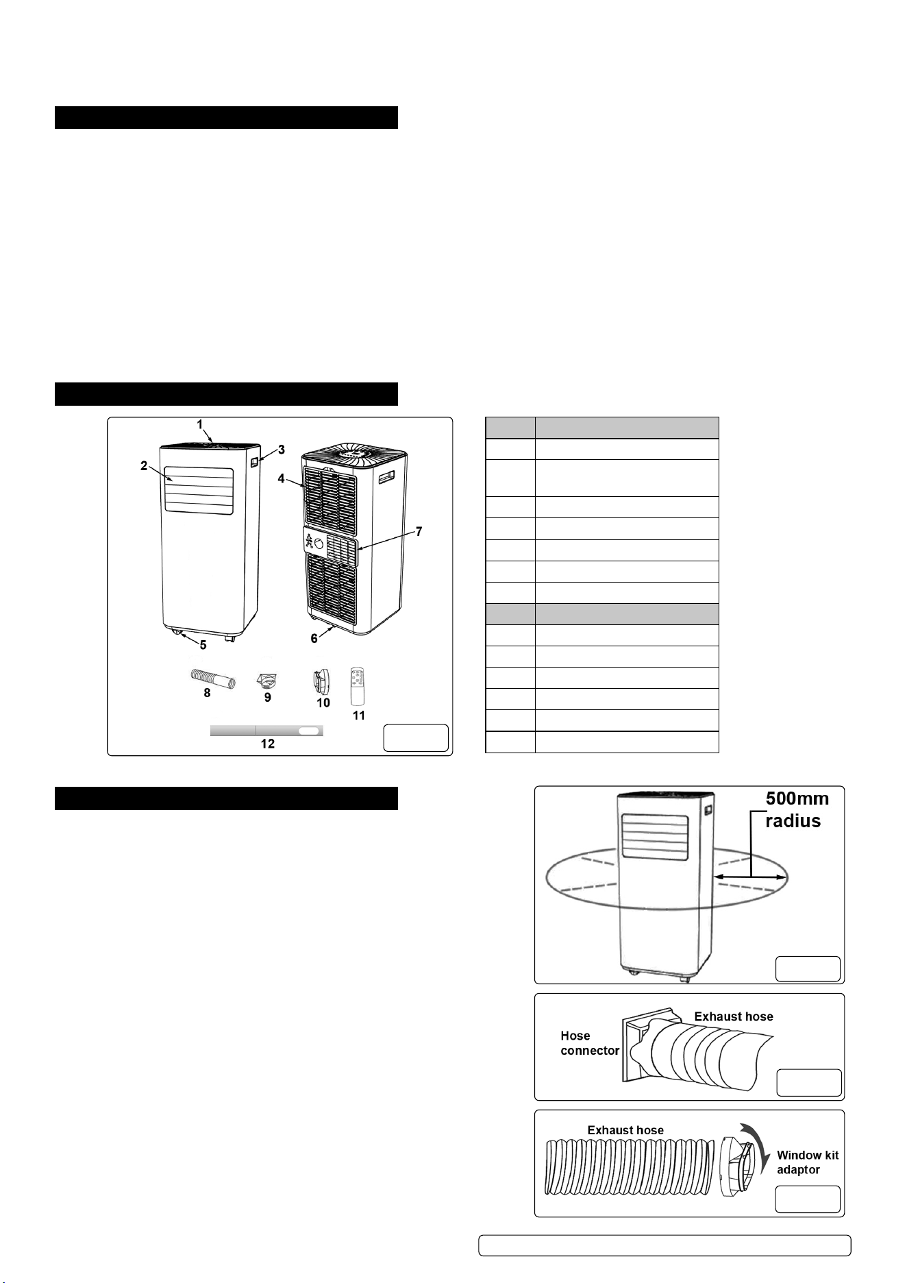
4. CONTENTS
5. INSTALLATION
Unpack the product and check contents. Should there be any damaged or
missing parts contact your supplier immediately.
5.1. LOCATION
5.1.1. Place the appliance on a rm, level surface.
5.1.2. Ensure that there is a clear area of at least 500mm around the appliance
(g.2) to allow for adequate air circulation.
8 DO NOT operate the appliance in close proximity to walls, curtains or other
objects that may block the air inlet or outlet.
WARNING! DO NOT locate the appliance where it is subject to:
- Heat sources such as radiators, ovens or similar
- Direct sunlight
- Mechanical vibration or shock
- Excessive dust
- Lack of ventilation i.e. inside a cabinet or bookcase
- Uneven surfaces
5.2. ASSEMBLE THE EXHAUST HOSE
WARNING! The air conditioning unit must be vented to outside. This ensures
that any heat and moisture is removed from the designated room space.
5.2.1. Screw t the hose connector to one end of the exhaust hose (g.3).
5.2.2. Screw t the window kit adapter to the other end of the exhaust hose (g.4).
Model No.: .........................................................SAC9000.V3
Cooling Capacity: ..................................................9000Btu/hr
Discharge Side Pressure: ..........................................3.2MPa
Energy Rating: ....................................................A (EER:2.6)
IP Rating: .......................................................................IPX1
Mass of Refrigerant: .......................................................170g
Maximum Airow: .....................................................330m³/hr
Maximum Exhaust Hose Length: ...................................1.5m
Maximum Water Extraction Rate: .............................. 25L/day
Noise Level: .............................................................. 65db(A)
Power: .........................................................................1005W
Rated Capacity: ..........................................................2600W
Refrigerant: ................................................................... R290
Suction Side Pressure:...............................................0.7MPa
Supply: ................................................................ 230V~50Hz
ITEM DESCRIPTION
1 Control panel
2 Air outlet with adjustable
louvre
3 Handle
4 Air inlet and lter
5 Castor wheel
6 Drainage hole
7 Air exhaust
ACCESSORIES
8 Exhaust hose
9 Hose connector
10 Window kit adaptor
11 Remote control
12 Window kit
13 Drain hose (not shown)
g.1
g.3
g.4
g.2
Original Language Version
© Jack Sealey Limited
SAC7000.V2, SCS9002.V3,SACWK1 Issue 2 (1,9,F) 17/10/23
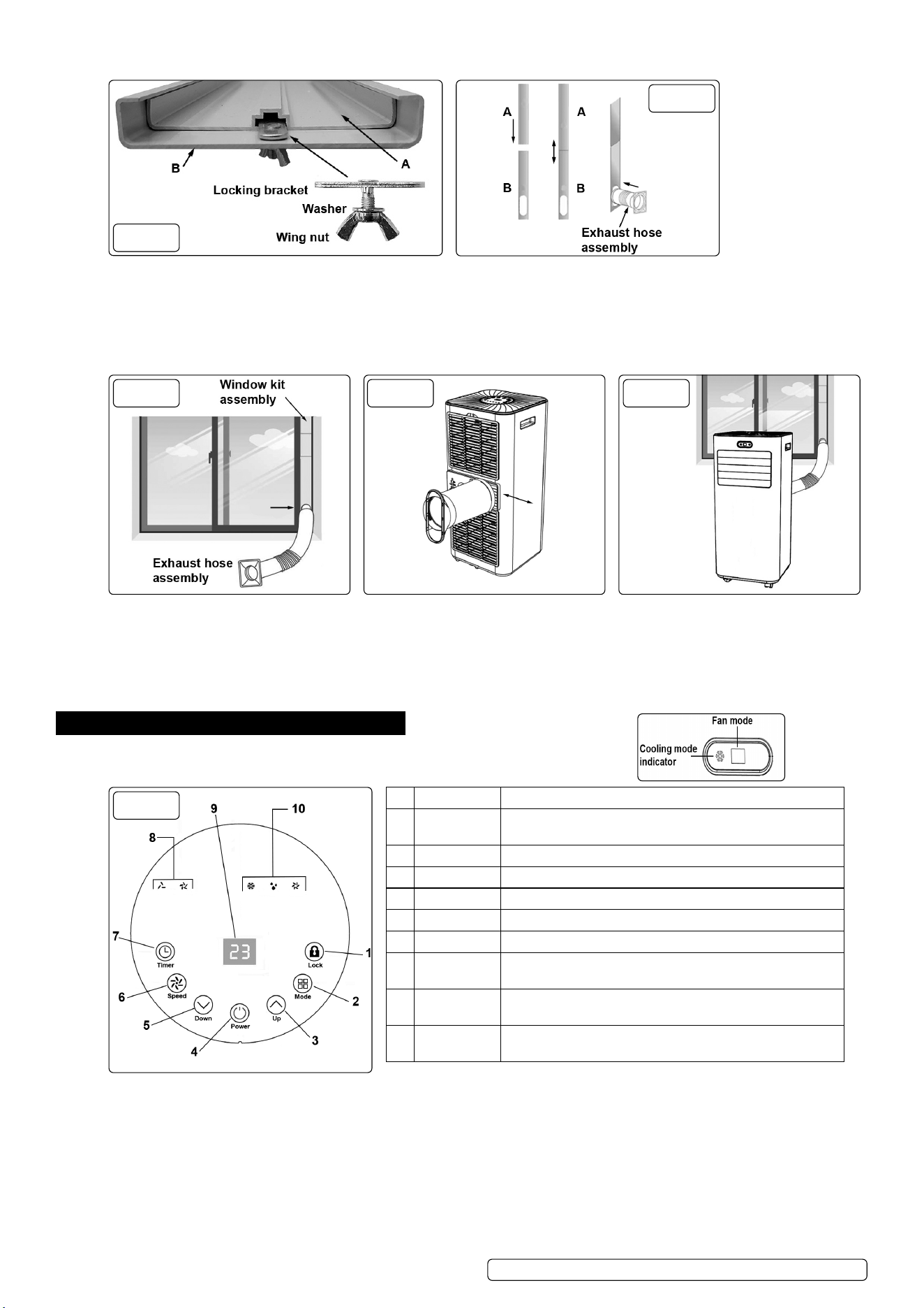
5.3. WINDOW KIT ASSEMBLY
g.5
g.6
5.3.1. Locate window kit locking bracket’s threaded shaft through hole in window kit part B (g.5).
5.3.2. Attach washer and wing nut to threaded shaft (g.5).
5.3.3. Slide window kit part A into part B (g 6) and locate locking bracket plate into central slot on part A (g.5).
5.3.4. Extend the adjustable window kit to suit the size of the window and tighten the wing nut (g.5) to lock.
5.3.5. Attach exhaust hose assembly, see section 5.2, to window kit part B (g.6).
5.4. ATTACH WINDOW KIT ASSEMBLY SEE ALSO SECTION 10 FOR ALTERNATIVE WINDOW KIT INCLUDED WITH THE MODELS
g.7 g.8 g.9
5.4.1. Open the window and place the window kit into position, then close the window onto the window kit (g.7).
NOTE: To obtain maximum eciency it is recommended that any gaps between the window kit and the sides of the window are sealed.
5.4.2. Attach the hose connector on the hose assembly to the exhaust outlet (g.1 #7) by sliding the it horizontally into position (g.8).
5.4.3. Place the appliance near to a suitable electrical power outlet and adjust the exible exhaust hose to suit, avoiding any sharp bends to
the hose (g.9).
5.4.4. Adjust the louvre panel (g.1 #2) to suit (g.9).
6. OPERATION
6.1. CONTROL PANEL AND DISPLAY
6.1.1. The display on the front face of the unit will only light when the unit is in cooling mode.
g.10
1 LOCK Press to turn ON or OFF the child lock function
2 MODE Press to switch operation mode between cooling,
dehumidifier and fan
3 UP Increase temperature (16ºC~32ºC) or timer setting
4 POWER Press to turn the unit ON or OFF
5 DOWN Decreasing the temperature or timer setting
6 SPEED Press to switch the fan speed between HIGH or LOW
7 TIMER Sets a time for the unit to automatically START or STOP
8 FAN SPEED
INDICATOR
Displays HIGH or LOW fan speed
9 DIGITAL
DISPLAY
Displays timer setting and room temperature
10 MODE
INDICATOR
Mode display between Cooling, Dehumidifying and Fan
6.2. SETTINGS
6.2.1. START UP AND SHUTDOWN
6.2.1.1. Press POWER to turn the unit ON (g.10 #4).
6.2.1.2. Press MODE button to select the desired operation mode (g.10 #2).
6.2.1.3. Press POWER again to turn the unit OFF (g.10 #4).
6.2.2. OPERATION MODE
The unit has four operation modes: Cool, dehumidier, fan and sleep.
6.2.3. COOLING A ROOM
6.2.3.1. Select the COOL mode to lower the temperature in a room.
6.2.3.2. Press MODE button (g.10 #2) until the COOL indicator illuminates (g.10 #10).
Original Language Version
© Jack Sealey Limited
SAC7000.V2, SCS9002.V3,SACWK1 Issue 2 (1,9,F) 17/10/23
6.2.3.3. Press the UP or DOWN button (g.10 #3 #5) to adjust the temperature to the desired level. The temperature will be displayed on
the screen (g.10 #9). The temperature can be set between 16ºC to 32ºC.
6.2.3.4. Press the Speed button (g.10 #6) Until the desired fan speed indicator illuminates (g.10 #8).
NOTE: The horizontal air ow direction is controlled by adjusting the air outlet louvres (g.1 #2).
WARNING! The air conditioner function will stop if the room temperature is lower than the selected temperature.
6.2.4. VENTILATE THE ROOM
6.2.4.1. Press the MODE button (g.10 #2) until the FAN indicator illuminates (g.10 #10).
NOTE: In ventilation mode the room air is circulated NOT cooled.
6.2.4.2. Press the Speed button (g.10 #6) Until the desired fan speed indicator illuminates (g.10 #10).
6.2.5. DRYING THE ROOM
6.2.5.1. Press the MODE button on the control panel (g.10 #2) until the DRY indicator illuminates (g.10 #10), or
press the DRY button on the remote control (g.11).
6.2.5.2. Connect the drain hose (fig.1 #13) To the drain outlet at the bottom of the unit (fig.1 #6). See section 6.5.
NOTE: In this mode the fan speed is set to low level and cannot be changed.
6.2.6. SLEEP MODE
WARNING! This function can only be activated by using the SLEEP button on the remote control (g.11).
To activate the sleep mode the unit must be in the COOL mode.
6.2.6.1. To activate COOL mode press the COOL button on the remote control and then press the SLEEP (g.11).
NOTE: After 1 hour the pre-set temperature is increased by 1ºC and increased again by 1ºC the following hour.
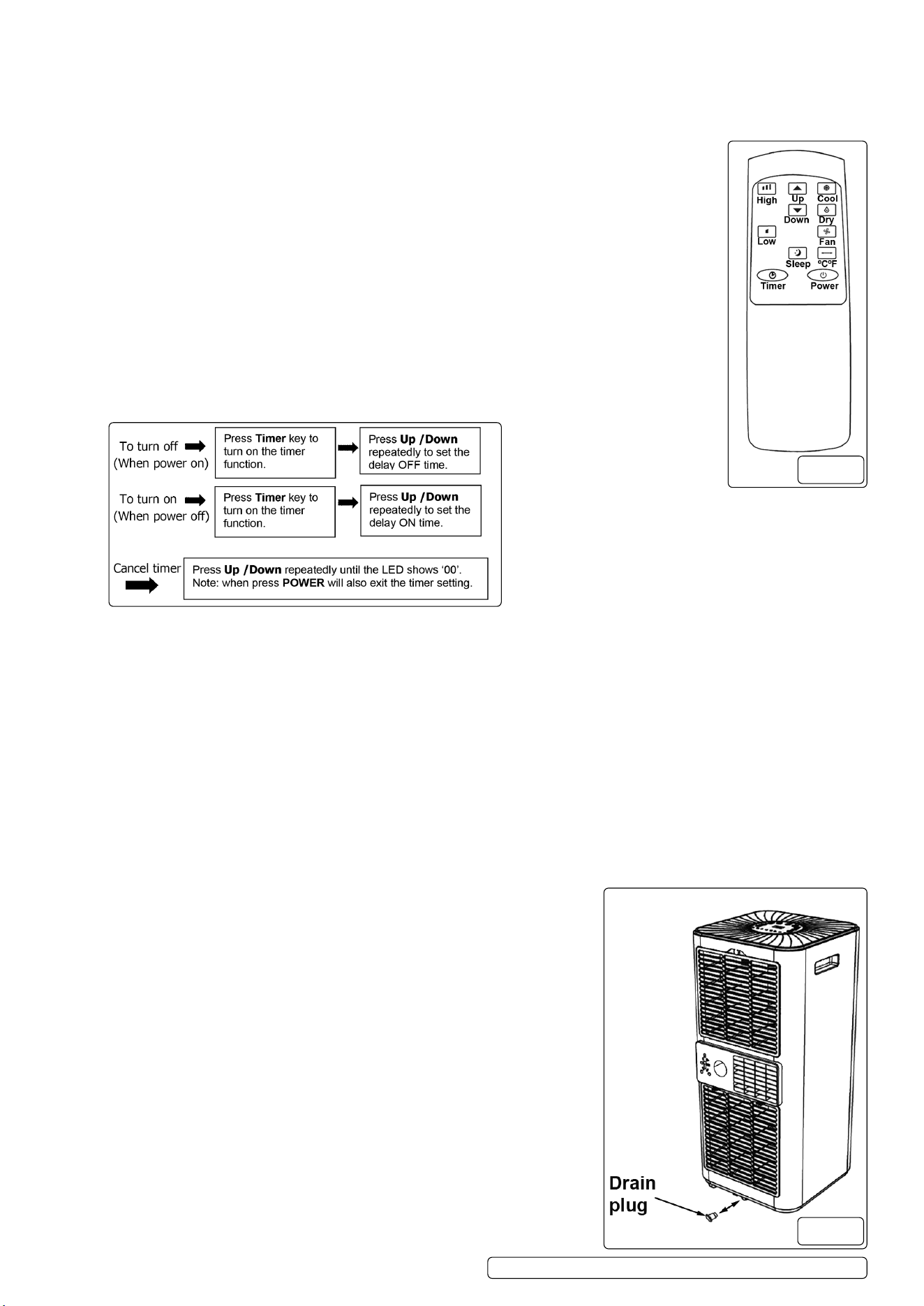
6.2.7. TIMER SETTING (1 to 24 hours)
6.2.7.1. The TIMER has two ways of operation and can be activated by either the button on the control panel (g.10
#7) or by the TIMER button on the remote control (g.11).
6.3. AUTOMATIC DEFROST
During use if operating at low room temperatures frost may build up at the evaporator. The POWER indicator will start to blink and the
unit will automatically begin to defrost.
The defrost control sequence is as follows:
A. If operating the unit in either the cooling or drying mode, the ambient temperature sensor senses that the evaporator coil
temperature is below -1ºC the compressor will stop. It will restart again, in the COOL mode, after 10 minutes or when the coil reaches
the temperature of 7ºC.
B. If operating the unit in the drying mode, the coil temperature sensor senses that the temperature of the evaporator is below 40ºC
and the dierential temperature between the coil temperature and the ambient room temperature is below 19ºC and the compressor
has been in operation for twenty minutes the unit will start defrosting for ve minutes and the POWER indicator will begin to blink.
6.4. OVERLOAD PROTECTION
If there is a loss of power, to protect the compressor, there is a three minute delay until the compressor will restart.
6.5. MANUAL DRAINAGE
NOTE: When the unit is full of water it will automatically shut o.
6.5.1. Switch o the unit and remove the electrical plug from it’s power source.
6.5.2. With care move the unit to suitable location to enable a container to be located below the bottom drainage hole (g.1 #6).
6.5.3. With the container in place remove the drain plug (g.12).
WARNING! The water will ow out instantly from the drainage hole.
6.5.4. When the unit has completely drained replace the drain plug back fully into the
drainage hole.
NOTE: To assist with drainage the unit can be slightly tilted backwards to allow the
drain plug to be re-inserted if the container becomes full.
6.5.5. Replace the electric plug into the power source and re-start the appliance in the
desired mode.
WARNING! Ensure that the drain plug is fully inserted, otherwise the condensate
water will ow out onto the oor.
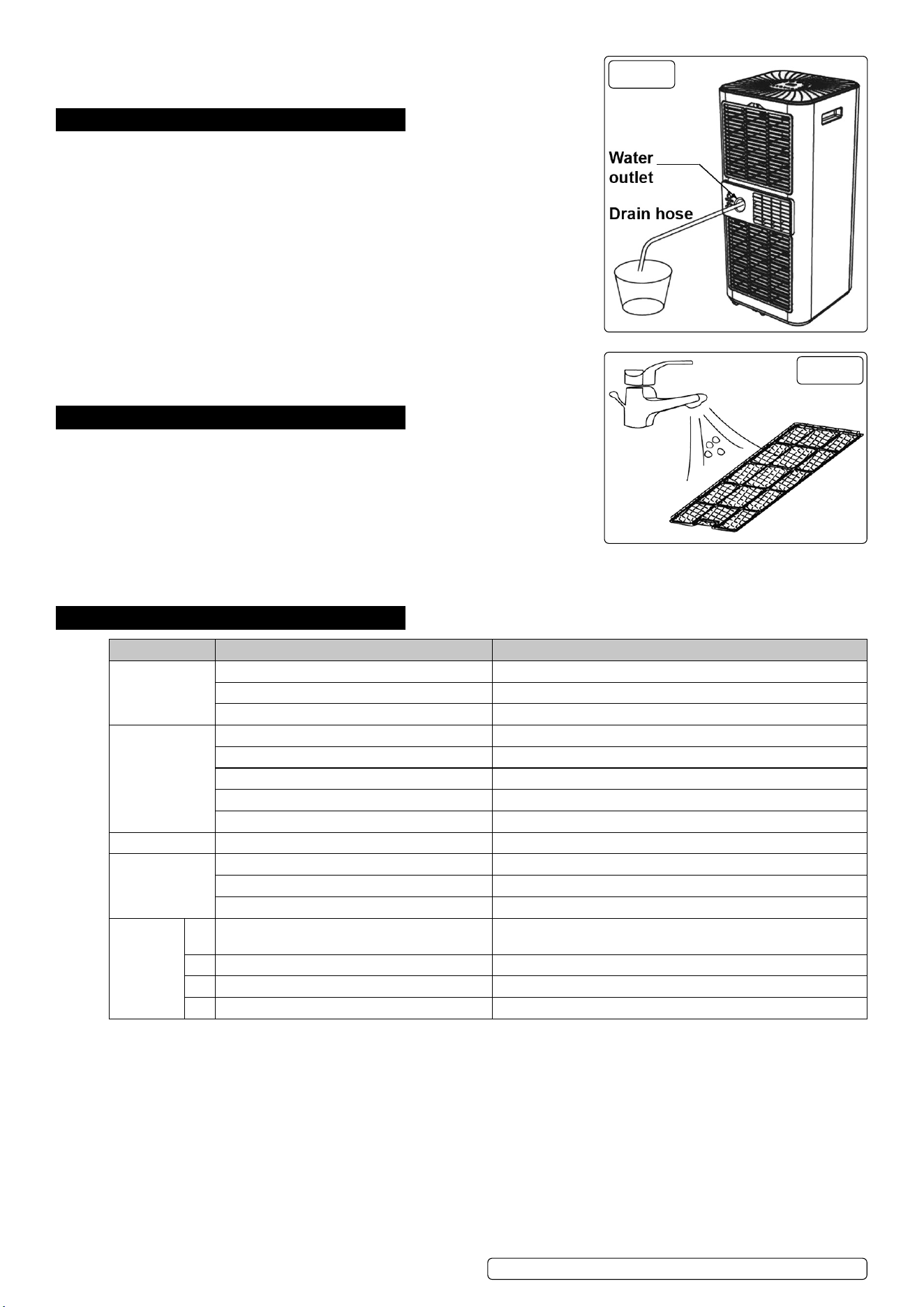
6.6. CONTINUOUS DRAINAGE
To provide a more ecient performance the self-evaporating system uses the
collected water to cool the condenser coils.
It is recommended not to use the continuous drain method in the cooling mode.
The condensate water evaporates at the condenser and is expelled through the
exhaust hose.
6.6.1. Switch o the unit and remove the electrical plug from it’s power source.
6.6.2. Release the cover from the water outlet opening (g.13).
6.6.3. With care push t one end of the drain hose onto the water outlet (g.13).
6.6.4. Securely place the other end of the drain hose over a suitably sized container or drain.
WARNING! Ensure that the drain hose is straight and free from any kinks and at an
inclination angle downwards of not more than 20º.
g.11
g.12
Original Language Version
© Jack Sealey Limited
SAC7000.V2, SCS9002.V3,SACWK1 Issue 2 (1,9,F) 17/10/23
8 DO NOT allow the open end of the drain hose to be submerged into the water. This
may cause an air lock in the hose.
NOTE: The condensate water will automatically ow into the container or drain.
7. MAINTENANCE
NOTE: Maintenance, service and repair must be carried out by qualied person.
Contact your Sealey stockist for details.
7.1. CLEANING
7.1.1. Switch o the unit and remove the electrical plug from it’s power source.
7.1.2. Clean the unit with soft damp cloth.
8 DO NOT use solvents.
7.2. CLEANING THE AIR FILTER
The air lter requires regular cleaning. A restricted airow will reduce the eciency of
the system.
It is recommended that air lter is cleaned every two weeks.
8 DO NOT operate the unit without an air lter.
7.2.1. Switch o the unit and remove the electrical plug from it’s power source.
7.2.2. Remove the lter mesh from the unit (g.1 #4).
7.2.3. Use a household vacuum to remove any dust from the lter.
7.2.4. Turn the lter over and rinse the lter under running water (g.14).
7.2.5. Allow the lter to dry before reinstalling.
8. STORAGE
8.1. Turn on the unit and select the low wind ventilation mode. See section 6.2.4.
8.1.1. Leave in this condition until the drainage pipe becomes dry.
NOTE: This will help prevent mildew.
8.2. Switch o the unit and remove the electrical plug from it’s power source.
8.3. Remove the window kit, exhaust hose and drain hose.
8.4. Drain the remaining water from the unit. See section 6.5.
8.5. Replace any drainage plugs.
8.6. Clean the lter. See section 7.2.
8.7. Remove the batteries from the remote control.
8.8. Store the unit and accessories in it’s original packaging, in safe dry childproof location.
9. TROUBLESHOOTING
SYMPTOM POSSIBLE CAUSE REMEDY
The unit is not
working
No power Connect to power source and turn the unit ON
Full water indicator is illuminated Drain the water
Low room temperature Change the set temperature
The unit works
with reduced
capacity
Dirty air filter Clean the air filter as required
Air ducts are blocked Clear obstacles. Re-position unit into clear space
Doors or windows open Close the doors and windows
Incorrect mode and temperature selected Select correct mode and temperature to suit desired application
Detached exhaust hose Securely reattach exhaust hose
Water leakage The drain hose is kinked or bent Straighten the drain hose
Excessive noise The unit is on an uneven surface Place the unit onto a flat horizontal surface
Loose, vibrating parts Check for loose parts and re-tighten
Water flowing sound Normal sound of refrigerant flowing
Error
codes
E0 Communication faults between main PCB and
display PCB
Contact Sealey service centre
E1 Ambient temperature sensor fail Contact Sealey service centre
E2 Coil temperate sensor failures Contact Sealey service centre
Ft Condensate water high level alarm Drain the water
g.13
g.14
Original Language Version
© Jack Sealey Limited
SAC7000.V2, SCS9002.V3,SACWK1 Issue 2 (1,9,F) 17/10/23
WINDOW SEALING KIT FOR AIR CONDITIONER DUCTING
MODEL NO: SACWK1
10. SAFETY
8 DO NOT cover the unit with this material, and do not obstruct the air inlet and outlet grilles of the machine with items such as
clothing,soft furnishings, furniture, bedding etc.
8 DO NOT use the material for any purpose other than that for which it is designed.
8 DO NOT use in bathroom or shower room.
8 DO NOT allow children to use, when not in use,store in a safe, cool, dry, childproof area.
NOTE: This material is not intended for use by persons (including children) with reduced physical, sensory or mental capabilities or
lack of experience and knowledge, unless they have been given supervision or instruction concerning the use of the appliance by a
person responsible for their safety. Children should be supervised to ensure that they do not play with this material.
11. INTRODUCTION
Suitable for all types of hinged windows including skylights up to 300cm total perimeter. Easy to install using the supplied roll of
self-adhesive hook & loop tape. Double zip makes positioning the ducting at any height easy. Saves energy by making the air
conditioner or dryer more eective.
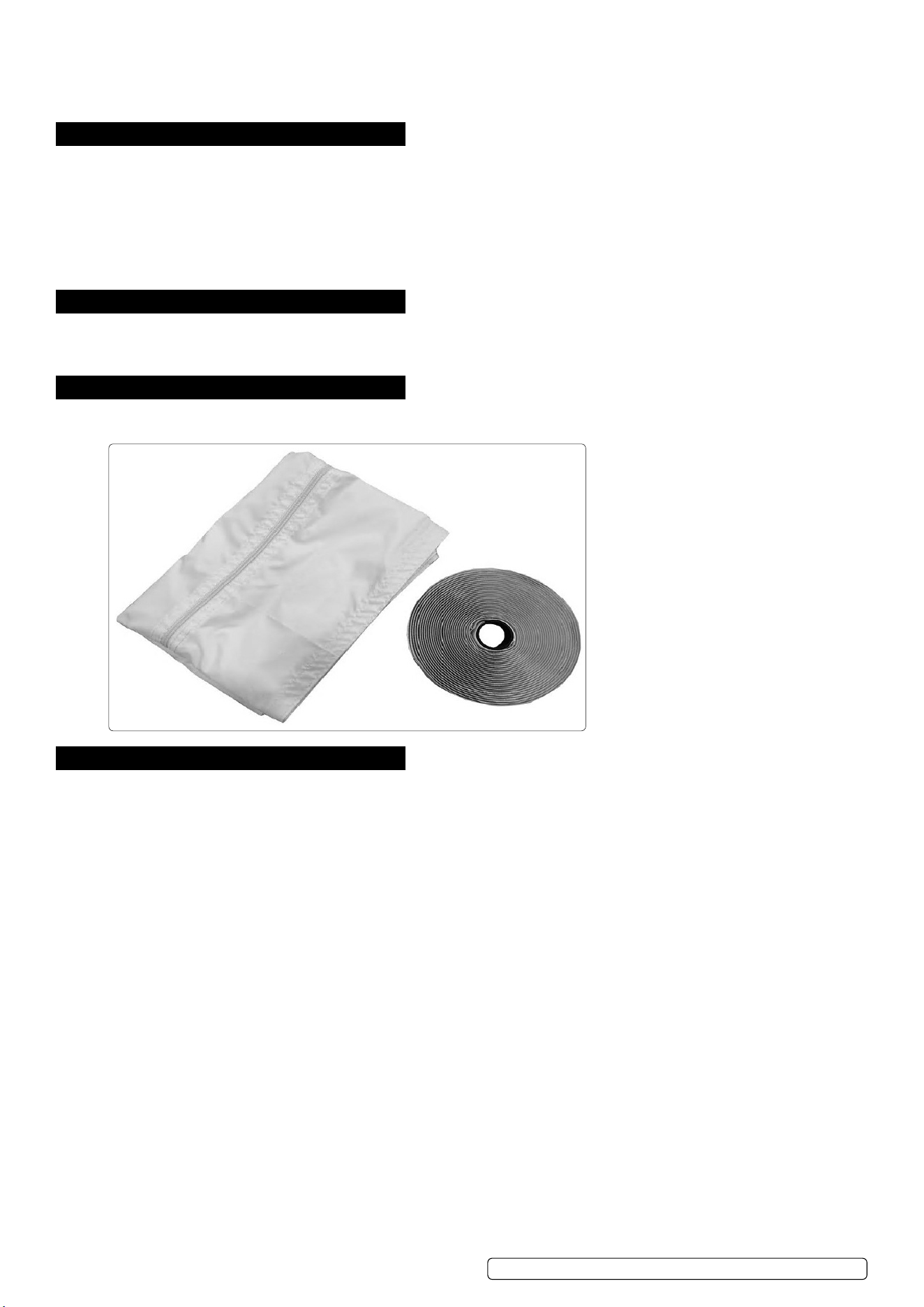
12. CONTENTS
Window seal
Velcro tape
Window seal with zip
Velcro tape
13. INSTRUCTIONS
13.1. CLEANING
Clean the window and window frame, making them free from grease and dust.
13.2. CUTTING THE VELCRO TAPE TO SIZE
Cut the Velcro tape to size, using a pair of scissors. Mark the middle (M) of the window seal (Fig. 1). Mark the middle of the window
frame and the casement (Fig. 2-4) ( Fig.2 shows an open window, Fig.3 a tilted window and Fig.4 an open skylight).
13.3. VELCRO TAPE TO THE WINDOW FRAME
Adhere the Velcro tape to the window frame around the window. Then adhere the Velcro tape fully around the window. Stick the Velcro
tape to the front side (in most cases 1 cm wide) of the casement or to the inner surface of the casement (where the window handle is
attached).
CAUTION: DO NOT adhere the Velcro tape on the window.
13.4. SEALING WINDOW TO WINDOW FRAME
Adhere the narrow side of the window seal to the Velcro tape on the window frame. Work from the centre and fully adhere the
narrow side all the way around. First fasten side A, then side B, starting in the middle and working all the way to the left and right.
IMPORTANT! When fastening, point A must be exactly opposite point B.
13.5. SEALING THE WINDOW
Leave the window ajar and adhere the wide side of the window seal to the Velcro tape of the window.
CAUTION: Leave sucient space, so that the window seal will not get jammed.
13.6. OPENING THE WINDOW SEAL
Open the zip of the window seal approximately 50 cm. Open the zip preferably at the positions marked with “S” and attach the exhaust
air hose.
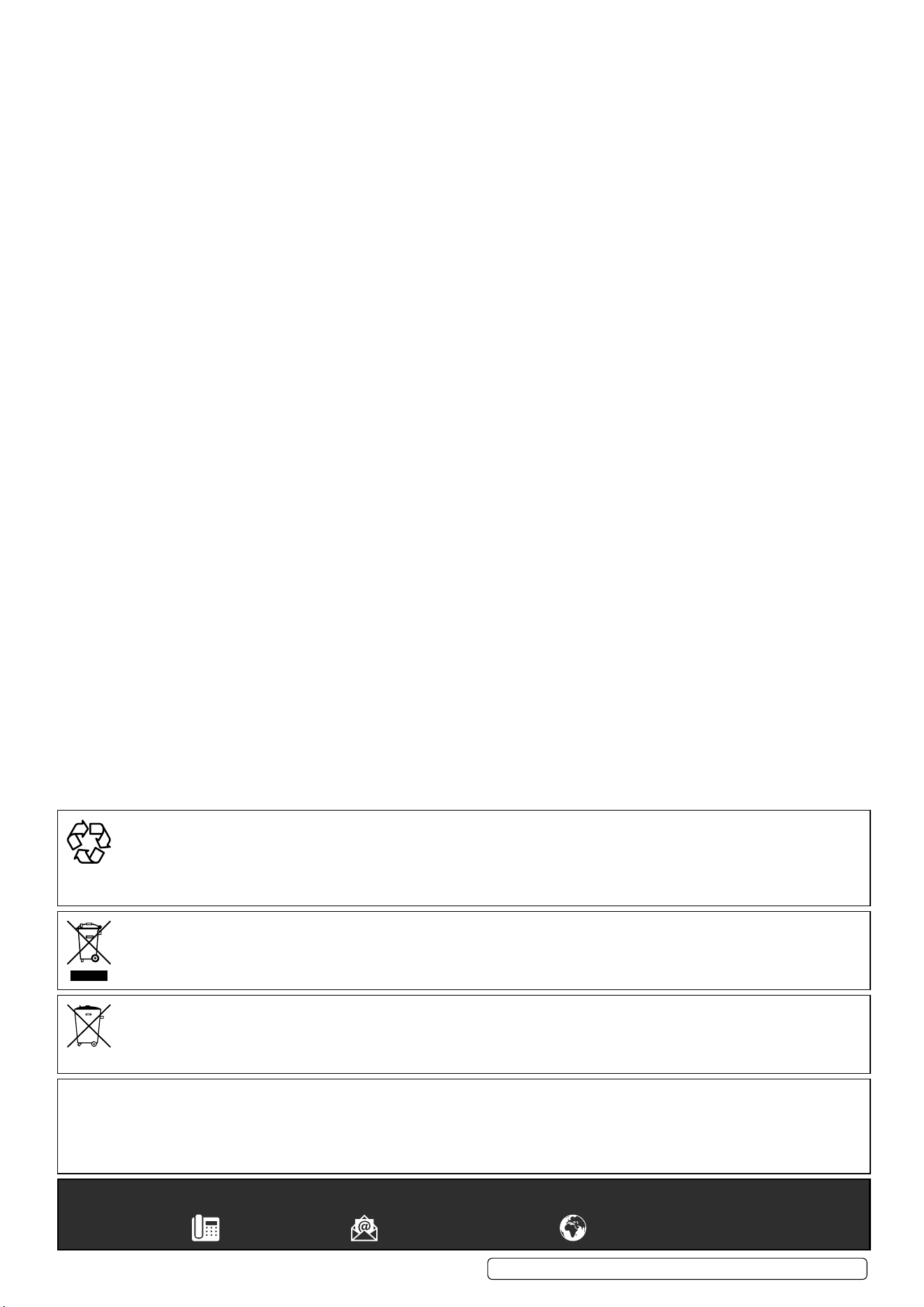
13.7. ATTACHING THE AIR DISCHARGE
Insert the air discharge hose of the air conditioning system through the hole in the window seal and close the zip until the air discharge
hose is properly secured.
13.8. CLOSING THE WINDOW
If you want to close your window, simply detach the cloth from the Velcro tape. When closing the window take care that the seal is not
jammed between the casement and window frame.
NOTE: This window seal ensures that the room remains cool for a longer period of time and keeps insects and mosquitoes out.
13.9. The installed item will resemble g.5 and g.6.
Original Language Version
© Jack Sealey Limited
SAC7000.V2, SCS9002.V3,SACWK1 Issue 2 (1,9,F) 17/10/23
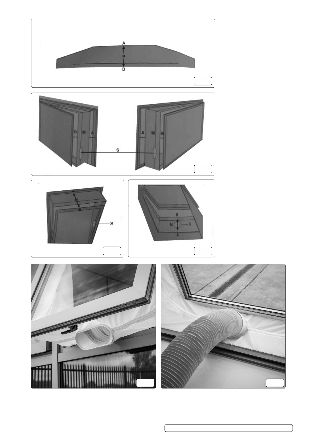
M = MIDDLE
POLYESTER
MATERIAL
g.1
g.2
OPEN WINDOW
g.3
TILTED WINDOW
g.4
OPEN SKYLIGHT
g.5 g.6
Original Language Version
© Jack Sealey Limited
SAC7000.V2, SCS9002.V3,SACWK1 Issue 2 (1,9,F) 17/10/23
Original Language Version
© Jack Sealey Limited
ENVIRONMENT PROTECTION
Recycle unwanted materials instead of disposing of them as waste. All tools, accessories and packaging should be sorted, taken to
a recycling centre and disposed of in a manner which is compatible with the environment. When the product becomes completely
unserviceable and requires disposal, drain any fluids (if applicable) into approved containers and dispose of the product and fluids
according to local regulations.
WEEE REGULATIONS
Dispose of this product at the end of its working life in compliance with the EU Directive on Waste Electrical and Electronic Equipment
(WEEE). When the product is no longer required, it must be disposed of in an environmentally protective way. Contact your local solid
waste authority for recycling information.
BATTERY REMOVAL: REMOVE BATTERY FROM REMOTE
Under the Waste Batteries and Accumulators Regulations 2009, Jack Sealey Ltd are required to inform potential purchasers of products
containing batteries (as defined within these regulations), that they are registered with Valpak’s registered compliance scheme. Jack
Sealey Ltd Batteries Producer Registration Number (BPRN) is BPRN00705.
Note: It is our policy to continually improve products and as such we reserve the right to alter data, specifications and component parts without prior
notice. Please note that other versions of this product are available. If you require documentation for alternative versions, please email or call
our technical team on technical@sealey.co.uk or 01284 757505.
Important: No Liability is accepted for incorrect use of this product.
Warranty: Guarantee is 12 months from purchase date, proof of which is required for any claim.
Sealey Group, Kempson Way, Suffolk Business Park, Bury St Edmunds, Suffolk. IP32 7AR
01284 757500 sales@sealey.co.uk www.sealey.co.uk
SAC7000.V2, SCS9002.V3,SACWK1 Issue 2 (1,9,F) 17/10/23