

Copyright
©2022 Hanwha Techwin Co., Ltd. All rights reserved.
Trademark
Each of the trademarks herein is registered. The name of this product and other trademarks mentioned in this manual are the registered
trademarks of their respective company.
Restriction
This document is protected by copyright. Under no circumstances, this document shall be reproduced, distributed, or changed, partially or
wholly, without formal authorization.
Disclaimer
Hanwha Techwin makes its best to verify the integrity and correctness of the contents in this document, but no formal guarantee shall be
provided. Use of this document and the subsequent results shall be entirely on the user’s own responsibility. Hanwha Techwin reserves
the right to change the contents of this document without prior notice.
Warranty
Hanwha Techwin shall repair a product free of charge if the product does not work properly when operating it under normal usage
conditions. The warranty period for products is 3 years, except in the following events:
●
If a system malfunctions due to the execution of programs unrelated to system operation
●
If the product has changed over time or has defects caused by natural wear during use
●
Sensory phenomena that does not affect the quality and function (Example: sound)
❖Design and specifications are subject to change without prior notice.
You can download the latest version from the Hanwha Techwin web site. (www.hanwha-security.com)
❖The initial administrator ID is “admin,” and you need to set the password when logging in for the first time.
Please change your password every three months to safely protect personal information and to prevent damage from information theft.
Please note that the user is responsible for their security and any other problems caused by mismanaging a password.
Network Video Decoder
User Manual
• OVERVIEW
English _3
overview
• OVERVIEW
Standards Approvals
■
Any changes or modifications in construction of this device which are not expressly approved by the party responsible for compliance could void
the user's authority to operate the equipment.
■
This device complies with part 15 of the FCC Rules. Operation is subject to the following two conditions: (1) This device may not cause harmful
interference, and (2) this device must accept any interference received, including interference that may cause undesired operation.
■
This equipment has been tested and found to comply with the limits for a Class A digital device, pursuant to part 15 of the FCC Rules.
These limits are designed to provide reasonable protection against harmful interference when the equipment is operated in a commercial
environment.
This equipment generates, uses, and can radiate radio frequency energy and, if not installed and used in accordance with the instruction
manual, may cause harmful interference to radio communications. Operation of this equipment in a residential area is likely to cause harmful
interference in which case the user will be required to correct the interference at his own expense.
■
Reorient or relocate the receiving antenna.
■
Increase the separation between the equipment and receiver.
■
Connect the equipment into an outlet on a circuit different from that to which the receiver is connected.
■
Consult the dealer or an experienced radio/TV technician for help.
CAUTION
●
RISK OF EXPLOSION IF BATTERY IS REPLACED BY AN INCORRECT TYPE. DISPOSE OF USED BATTERIES
ACCORDING TO THE INSTRUCTIONS.
●
Do not ingest battery, Chemical Burn Hazard.
●
This product contains a coin / button cell battery. If the coin / button cell battery is swallowed, it can cause
severe internal burns in just 2 hours and can lead to death.
●
Keep new and used batteries away from children. If the battery compartment does not close securely, stop
using the product and keep it away from children.
If you think batteries might have been swallowed or placed inside any part or the body, seek immediate
medical attention.
ATTENTION
●
IL Y A RISQUE D'EXPLOSION SI LA BATTERIE EST REMPLACÉE PAR UNE BATTERIE DE TYPE INCORRECT.
METTRE AU REBUT LES BATTERIES USAGÉES CONFORMÉMENT AUX INSTRUCTIONS.
●
Ne pas ingérer la pile, risque de brûlure chimique.
●
Ce produit contient une pile de type bouton/pièce de monnaie. Si la pile de type bouton/pièce de monnaie est
avalée, elle peut causer de graves brûlures internes en seulement 2 heures et peut entraîner la mort.
●
Gardez les piles neuves et usagées hors de portée des enfants. Si le compartiment de la pile ne se ferme pas
correctement, cessez d’utiliser le produit et gardez-le d’atteinte des enfants.
Si vous suspectez que des piles ont été avalées ou insérées dans une partie du corps, consultez un médecin
sans tarder.
ImpORTANT SAfETy INSTRUCTIONS
Read these operating instructions carefully before using the unit.
Follow all the safety instructions listed below.
Keep these operating instructions handy for future reference.
1) Read these instructions.
2) Keep these instructions.
3) Heed all warnings.
4) Follow all instructions.
5) Do not use this apparatus near water.
6) Clean the contaminated area on the product surface with a soft, dry cloth or a damp cloth.
(Do not use a detergent or cosmetic products that contain alcohol, solvents or surfactants or oil constituents
as they may deform or cause damage to the product.)
7) Do not block any ventilation openings, Install in accordance with the manufacturer's instructions.
8) Do not install near any heat sources such as radiators, heat registers, stoves, or other apparatus (including
amplifiers) that produce heat.
9) Do not defeat the safety purpose of the polarized or grounding- type plug. A polarized plug has two blades
with one wider than the other. A grounding type plug has two blades and a third grounding prong. The
wide blade or the third prong are provided for your safety. if the provided plug does not fit into your outlet,
consult an electrician for replacement of the obsolete outlet.
10) Protect the power cord from being walked on or pinched particularly at plugs, convenience receptacles, and
the point where they exit from the apparatus.
11) Only use attachments/accessories specified by the manufacturer.
12) Use only with the cart, stand, tripod, bracket, or table specified by the manufacturer, or sold with the
apparatus. When a cart is used, use caution when moving the cart/apparatus combination to avoid injury
from tip-over.
13) Unplug this apparatus during lightning storms or when unused for long periods of time.
14) Refer all servicing to qualified service personnel. Servicing is required when the apparatus has been
damaged in any way, such as power-supply cord or plug is damaged, liquid has been spilled or objects have
fallen into the apparatus, the apparatus has been exposed to rain or moisture, does not operate normally, or
has been dropped.
15) This product is intended to be powered by a Listed Power Supply Unit marked “Class 2” or “LPS” or “PS2” and
rated as 12 VDC, 0.92 A or PoE (48 VDC), 0.27 A.
16) The wired LAN hub providing power over Ethernet (PoE) in accordance with IEEE 802.3.af must be a UL
Listed Device with its output evaluated as a Limited Power Source as defined in UL60950-1 or evaluated as
PS2 as defined in UL62368-1.
4_ overview
overview
AbOUT USER mANUAl
This user manual provides information necessary to use the product, including a brief introduction, names of each part,
functions, the connection method, and menu settings. Please read this manual carefully before using the product for
proper use.
●
This manual explains how to use the product based on the default values and the default screens.
●
The information in this manual may vary, depending on the product's software update and our policies, and is
subject to change without notice to the user.
●
Please note that we are not responsible for damage caused by using non-standard products or any other besides
those mentioned in the product specification manual.
●
If you need to open the case and repair the inside, please contact the place of purchase and get professional help.
AbOUT TARgET READERS
This manual contains information for users using the decoder.
AbOUT pRODUCT USAgE
Users of this product can perform the following operations:
●
Real-Time Monitoring of Registered Cameras to Decoder
Before using this product, please make sure that the product is the latest software version. You can visit Hanwha
Techwin's product homepage (http://security.hanwhatechwin.com/) to check and download the latest software version.
Warning
battery
There is a risk of explosion if the battery inside the product is incorrectly replaced, so be sure to use the same
battery used in the product.
The specifications of the battery in use are as follows.
●
Voltage: 3V
●
Capacity: 210 mAh
●
Continuous standard load: 0.4 mA
●
Usable temperature: -20°C - +60°C
■
Do not place the battery under direct sunlight or near a heat source, such as a heater.
Operating temperature
The operating temperature of this product is from 0°C to 40°C.
If left in an environment with a temperature below the range of operating temperature, the product may not
operate. If this occurs, try using the product after storing it at room temperature.
About Security
The initial administrator ID is “admin,” and you need to set the password when logging in for the first time.
Please change your password periodically every three months to safely protect personal information and to
prevent damage through information theft. Please note that the user is responsible for their security and any
other problems caused by mismanaging a password.

• OVERVIEW
English _5
CONTENTS
OVERVIEW
3
3 Important Safety Instructions
4 About User Manual
4 About Target Readers
4 About Product Usage
4 Warning
5 Contents
7 Features
7 Checking Package Contents
7 Names and Functions of the Product
8 Mounting the Multi Adapter
8 Mounting on the Monitor's VESA Holes
9 Mounting with Stud Screws
9 Mounting on a Pole
10 Connecting to an External Device
10 Connecting a USB device
10 Connecting to Power
10 Connecting to a Power Source with Ethernet
11 Connecting to the Ground Wire
11 Recommendations for the Ground Wire
11 Connecting the Network
11 Network connection via Ethernet (10/100/1000BaseT)
11 Connecting to a Network Using a Router
11 Connecting the Network Cameras
INSTAllATION
8
CONNECTINg
10
12 Starting the System
12 Login
13 Setting the System Operation Mode
13 Installation wizard
16 Shutting Down the System
16 Restarting the System
gETTINg STARTED
12
17 Screen Layout of the Live
18 Checking the System Status
18 Checking the Camera List
19 Live Screen Menu
20 Icons on the Live Screen
20 OSD Information Display
21 Channel Information Display
21 Checking the Camera Status
22 Channel Setting
22 Change Split Mode
22 Change Overall Aspect Ratio
23 Full Screen Mode
23 Layout Setup
23 Checking Layout List
24 Add Layout and Set Name
24 Delete Layout
24 Change of Layout Channel and Name
24 Dynamic Layout
26 Play Layout Sequence
26 Camera Video Control
26 Capture
27 Temperature Detection Mode
27 PTZ Mode
28 Zoom in
28 Audio
28 Change Channel Aspect Ratio
29 Dewarping
29 PTZ Control
29 Getting Started with PTZ Operations
29 PTZ Control Menu
30 Using Digital PTZ (D-PTZ) Function
30 Preset
31 Running Preset
31 Run Swing (auto pan), Group (scan), Tour, and Trace
(pattern)
lIVE
17

6_ overview
overview
lIVE VIEWER
54
SETUp VIEWER
57
51 What is Web Viewer?
51 Key Functions
51 System Requirements
51 Connecting Web Viewer
51 Setting the Decoder Password
52 Installation wizard
STARTINg WEb VIEWER
51
SETUp
32
54 Screen Layout of the Live Viewer
54 Checking User ID
55 Checking the Camera List
55 Checking the All Camera Status
55 Live Status
55 Changing the Pattern of Split Screen
56 Layout Setup
56 Checking Layout List
56 Adding Layout
56 Changing Layout Names
56 Changing Layout Channels
56 Deleting Layout
57 Screen Layout of the Setup Viewer
57 Setting the Camera
57 Channel setup
57 Camera setup
58 Profile setup
59 Camera password setup
59 Setting the Device
59 Monitor
60 Setting the Network
60 IP & Port
60 IP filtering
60 HTTPS
61 802.1x
61 SNMP
61 Setting the System
61 Date/Time/Language
62 User
62 System management
63 Log
32 Screen Layout of the Setup
32 Setting the Camera
32 Channel setup
35 Camera setup
36 Profile setup
39 Camera password setup
40 Setting the Device
40 Monitor
41 Setting the Network
41 IP & Port
43 IP filtering
43 HTTPS
44 802.1x
44 SNMP
45 Setting the System
45 Date/Time/Language
46 User
48 System management
50 Log
AppENDIx
64
64 Using Virtual Keyboard
64 Troubleshooting (FAQ)
• OVERVIEW
English _7
fEATURES
This product monitors the video and sound of the network camera.
The PC provides an environment where you can set up this product.
●
Provides new UI 2.0
●
Plays Layout Sequence
●
Supports thermal imaging cameras / PTZ linked cameras
●
Supports a range of 4K camera resolutions
●
Outputs a 4K high definition image using HDMI
●
Supports dual monitor output (expand, duplicate)
●
Supports ONVIF Profile S standard and RTP / RTSP protocols
●
Simultaneous plays of 64 channels
●
Supports live monitoring of the network camera
●
Installation Wizard Function (Decoder, Web Viewer)
ChECKINg pACKAgE CONTENTS
Please unwrap the product, and place the product in a flat place or in the place to be installed.
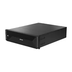
Please check the following contents are included in addition to the main unit.
Decoder Mouse Quick Guide
Multi adapter Terminal block M4 L20 stud (for VESA hole, 4 ea)
M4 L8 screw
(for multi adapter, 4 ea)
M3 L6 screw
(for decoder base hole, 2 ea)
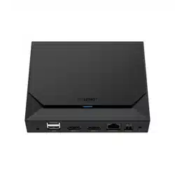
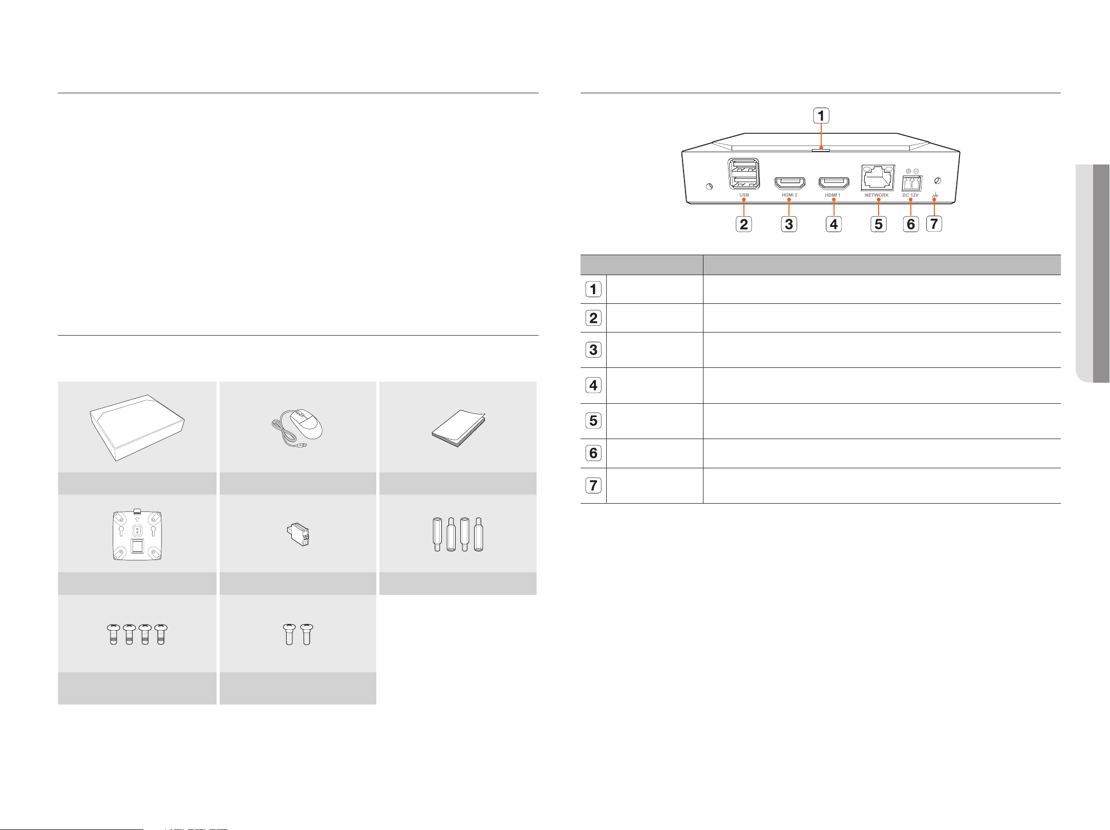
NAmES AND fUNCTIONS Of ThE pRODUCT
Name Functions
LED Indicator
Shows the power On/Off status.
USB
Connects the USB devices. (USB 2.0 supported)
HDMI 2
HDMI connector port.
●
Connector port that connects to the secondary monitor, and supports the maximum 1920 x 1080 60 Hz.
HDMI 1
HDMI connector port.
●
Connector pod that connects to the primary monitor, and supports the maximum 3840 x 2160 30 Hz.
NETWORK
Network port for camera connections.
●
Can be powered by PoE.
DC 12V
Terminal to connect the designated power to.
Ground Connection
Port for connecting a separate ground cable.
●
For safe handling of the device, please add a ground wire.
8_ installation
installation
Please take note of the followings before using this product.
●
Do not use the product outdoor.
●
Do not spill water or liquid in the connection part of the product.
●
Do not impose the system to excessive shock or force.
●
Do not pull out the power cord forcefully.
●
Do not disassemble the product on your own.
●
Do not exceed the rated input/output range.
●
Use a certified power cord only.
●
For the product with an input ground, use a grounded power plug.
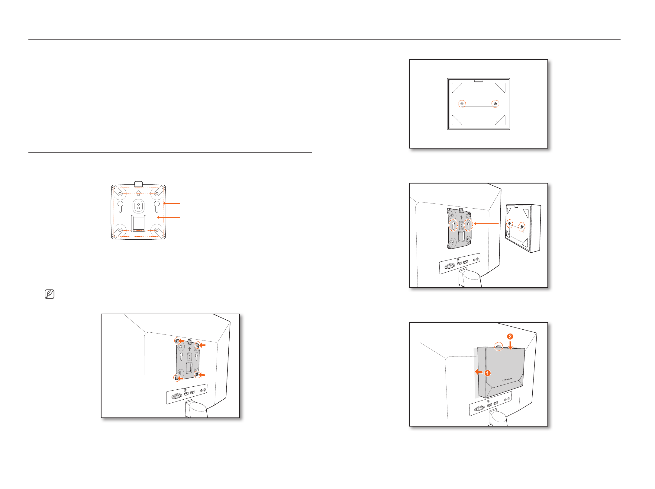
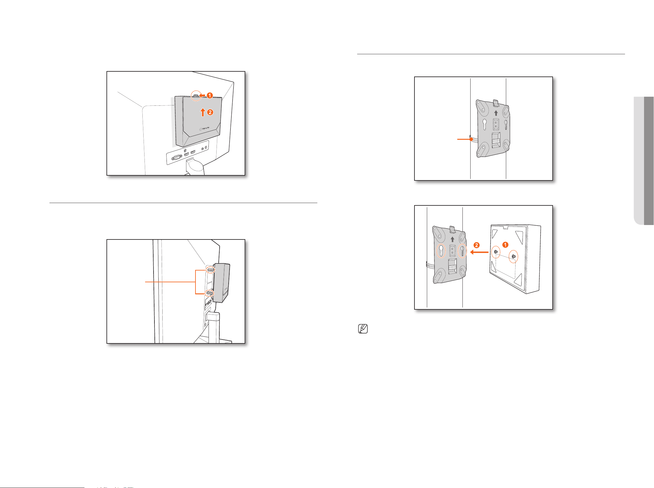
mOUNTINg ThE mUlTI ADApTER
You can mount the decoder on the monitor’s VESA holes or a pole by using a multi adapter.
The multi adapter supports the following VESA standards.
100 x 100 mm (outside)
75 x 75 mm (inside)
mounting on the monitor's VESA holes
1. Fix the multi adapter to the monitor by using four M4 L8 screws.
■
Confirm the VESA standard of the monitor on which you intend to mount the multi adapter.
2. Fasten two M3 L6 screws to the base of the decoder.
3. Make sure the screws on the base of the decoder go into the threaded holes of the multi adapter.
■
Mount the decoder with the connecting terminal facing down.
4. Press the decoder toward the monitor and then slide it down to fix it.
■
Press the decoder until the multi adapter's metal spring is exposed and fix the decoder.
• INSTAllATION
English _9
Disconnecting the multi Adapter
Lift the decoder while pressing the multi adapter's metal spring.
mounting with Stud Screws
If it is not possible to mount a decoder on the monitor because the monitor’s VESA holes are too close to the
monitor's connecting terminal or stand. You can use stud screws to mount the decoder.
Fasten four M4 L20 stud screws on the VESA holes on the back of the monitor, and mount the multi adapter.
M4 L20 stud screw
mounting on a pole
1. Mount the multi adapter on the pole using a strap.
Strap for poles
2. Fasten two M3 L6 screws on the base of the decoder, and mount the decoder to the multi adapter.
■
The strap for poles (SBP-100S) is sold separately.
10_ connecting
connecting
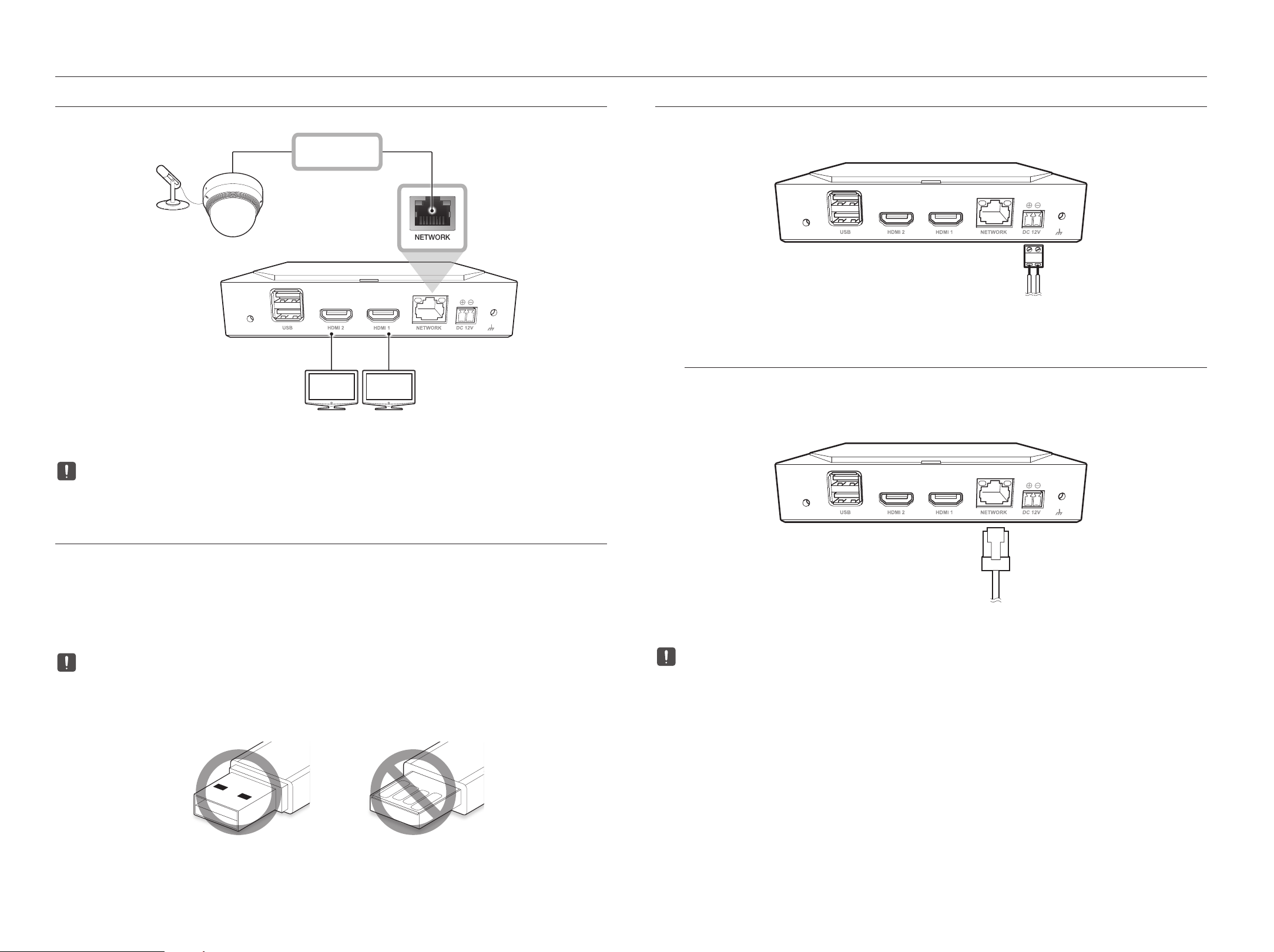
CONNECTINg TO AN ExTERNAl DEVICE
NETWORK
1
2
HDMI OUT HDMI OUT
Network
Microphone
Camera
■
Unrated or improper power source may cause damage to the system. Ensure that you use only the rated power source before connecting power to the
system.
CONNECTINg A USb DEVICE
1. On the front of the product, there is a USB port.
2. You can connect a USB memory or mouse to the USB port.
3. The product supports a hot-plugging function that enables connecting/disconnecting USB devices while operating
the system.
■
Some USB devices may fail to function properly due to compatibility issues, please check the device before using it.
■
If the USB memory is not detected, try formatting it on the "Setup > System > System management > Settings" menu.
■
Only USB storage devices that comply with the standards (having a metal cover) are guaranteed for data transfer.
■
In case the USB device’s electric contacts have been worn out, data transfer between the devices may not properly function.
CONNECTINg TO pOWER
When using a common ethernet cable, please connect to the power adapter for a power supply.
Connect the (+,-) wires of the power adapter to the power input port of the network video decoder using a screwdriver.
Power
Connecting to a power Source with Ethernet
You can supply power separately from the PoE switch without connecting to the power adapter.
●
Please see below for PoE power specifications.
– Power in use: PoE(IEEE802.3af)
Ethernet
■
When the PoE and DC 12V is powered on at the same time, the device operates with external power (DC 12V).
– If you connect to a PoE-enabled router, you can use the product without connecting to a separate power source.
– For the PoE, use equipment that supports the IEEE 802.3af standard.
■
Please be careful when connecting as DC 12V adapter has polarity.
■
When connecting to external devices, be sure to power off the connected device before connecting.
■
Connect the set and the adapter power line before connecting to a 220V wall socket.
■
Do not extend the adapter output cable.
■
Please contact the service center when you need to extend the power cable.
• CONNECTINg
English _11
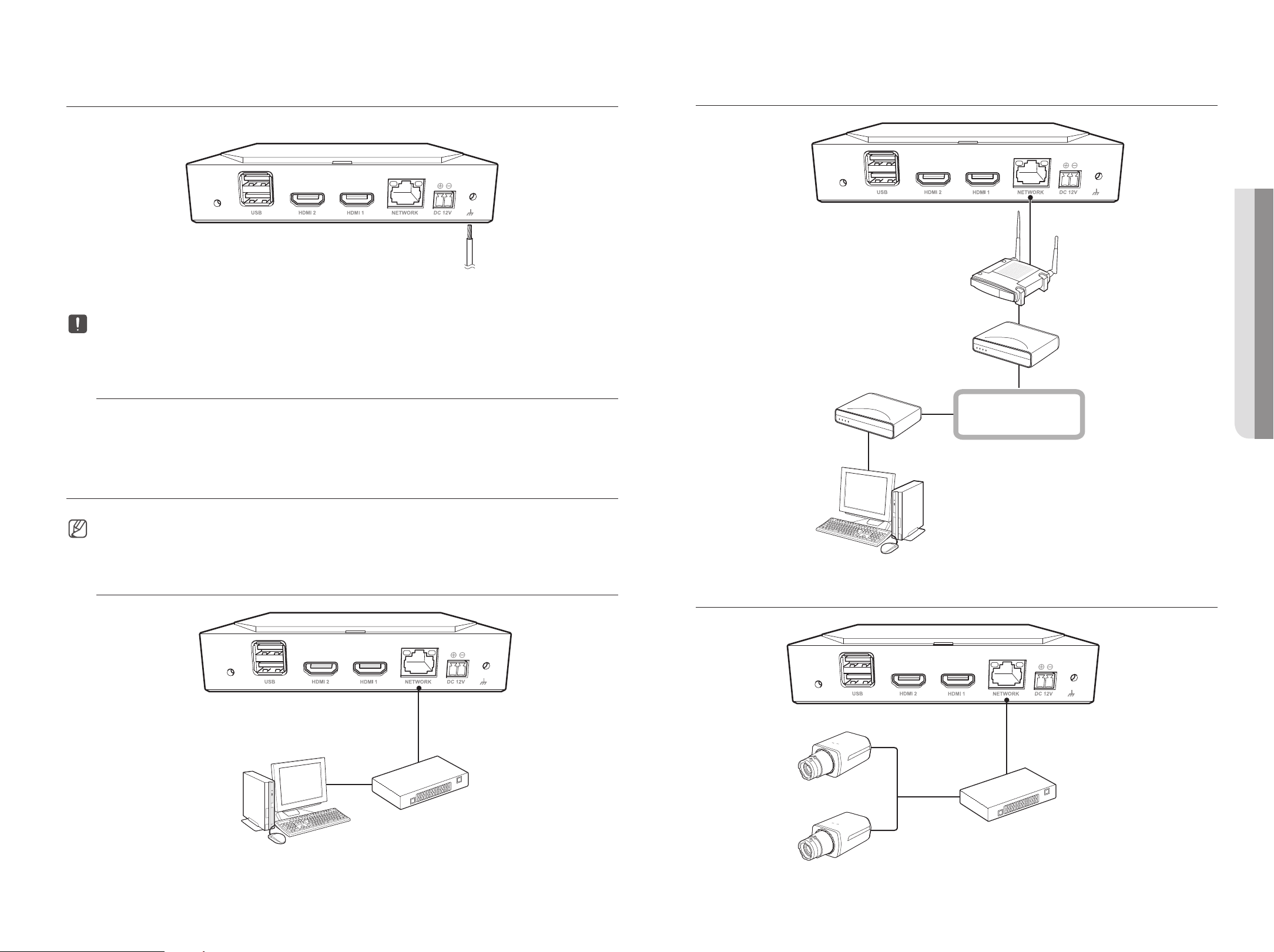
CONNECTINg TO ThE gROUND WIRE
Use a screwdriver on the FG screw on the right side of the power input port to connect it to the ground wire.
Ground wire
■
The ground wire prevents the product from being struck by lightning.
■
When connecting, be sure to power off the connected device before connecting.
Recommendations for the ground Wire
●
Length: within 3M
●
Size: over 18AWG
Example) UL1007 AWG18/16, UL1015 AWG18/16/14/12, UL2468 AWG18/16/14
CONNECTINg ThE NETWORK
■
For more information about network connections, see "Setting the Network" in the User Manual.
Network connection via Ethernet (10/100/1000baseT)
Windows
Network Viewer
Switch
Connecting to a Network Using a Router
Network
xDSL or Cable Modem
IP Router
xDSL or Cable Modem
Windows Network Viewer
Connecting the Network Cameras
Network Camera
Network Camera
Switch
12_ getting started
getting started
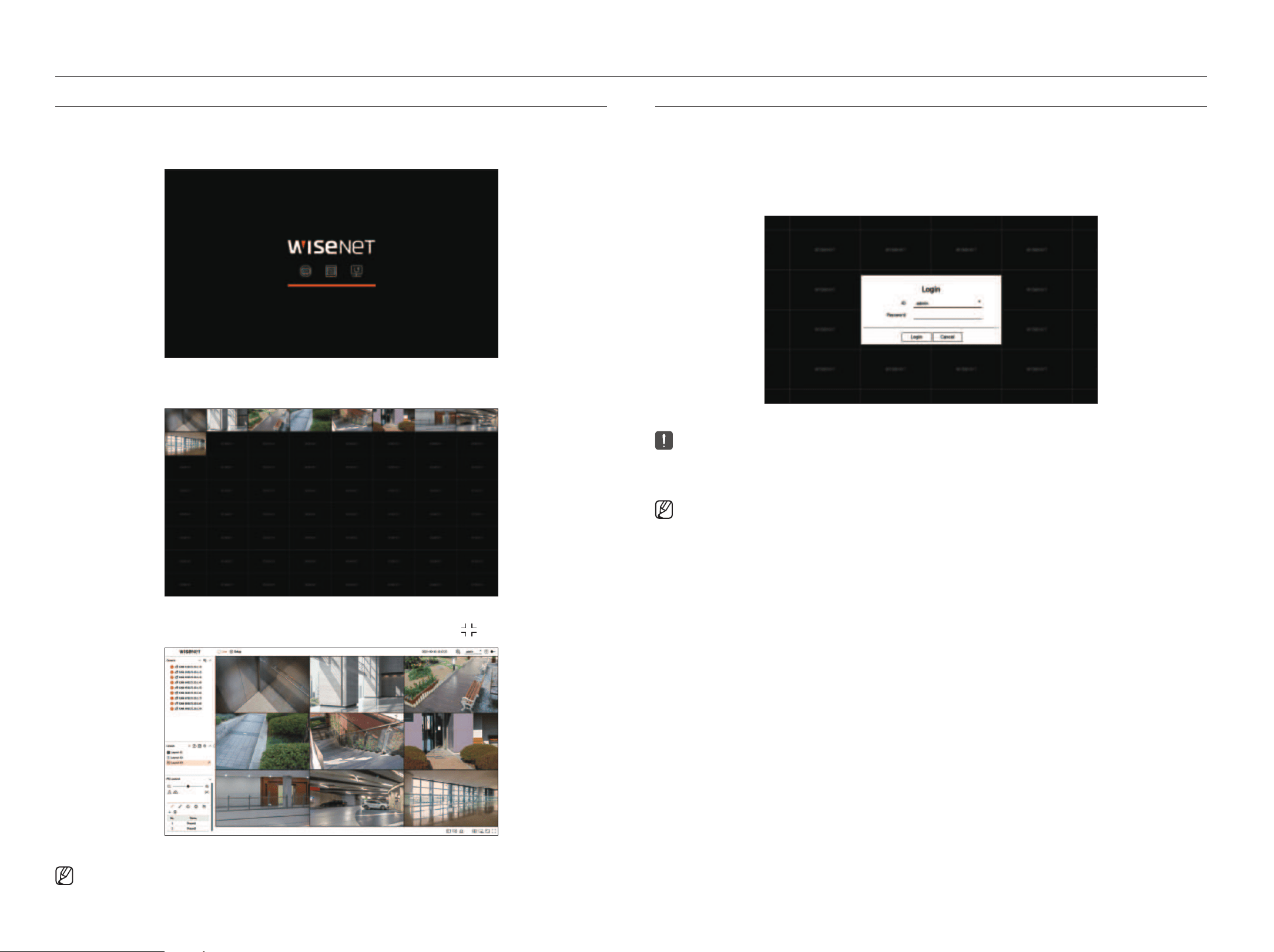
STARTINg ThE SySTEm
1. Connect the power cable of the decoder.
2. You will see the initialization screen.
3. After completing initialization, the Live screen on the full screen will appear.
4. To exit full screen, place your mouse cursor over the bottom of the screen and click <
>.
■
You can only exit full screen when it is in <Standalone> operation mode.
lOgIN
To use the decoder menu, you are required to login as a user that is authorized to access the menu.
1. Select <login> in the top right of the screen.
2. The
<login> confirmation pop-up window
will appear.
3. Enter the user ID and password, then click <login>.
■
The initial administrator ID is “admin” and you need to set the password in the installation wizard.
■
Please change your password every three months to safely protect personal information and to prevent damage from information theft.
Please note that the user is responsible for their security and any other problems caused by mismanaging a password.
■
For more information about limited-access permission, go to the "Setup > Setting the System > User” page in the table of contents.
English _13
• gETTINg STARTED
getting started
• gETTINg STARTED
INSTAllATION WIzARD
As shown below, proceed through each step of the <Installation wizard>.
Installation Wizard can only be accessed at factory default status. If you do not want to proceed, click <Exit>.
■
It will automatically change to the optimal monitor resolution and run the installation wizard.
■
If the installation wizard does not run, remove the monitor connection from the back of the decoder, reboot the decoder and reconnect the monitor.
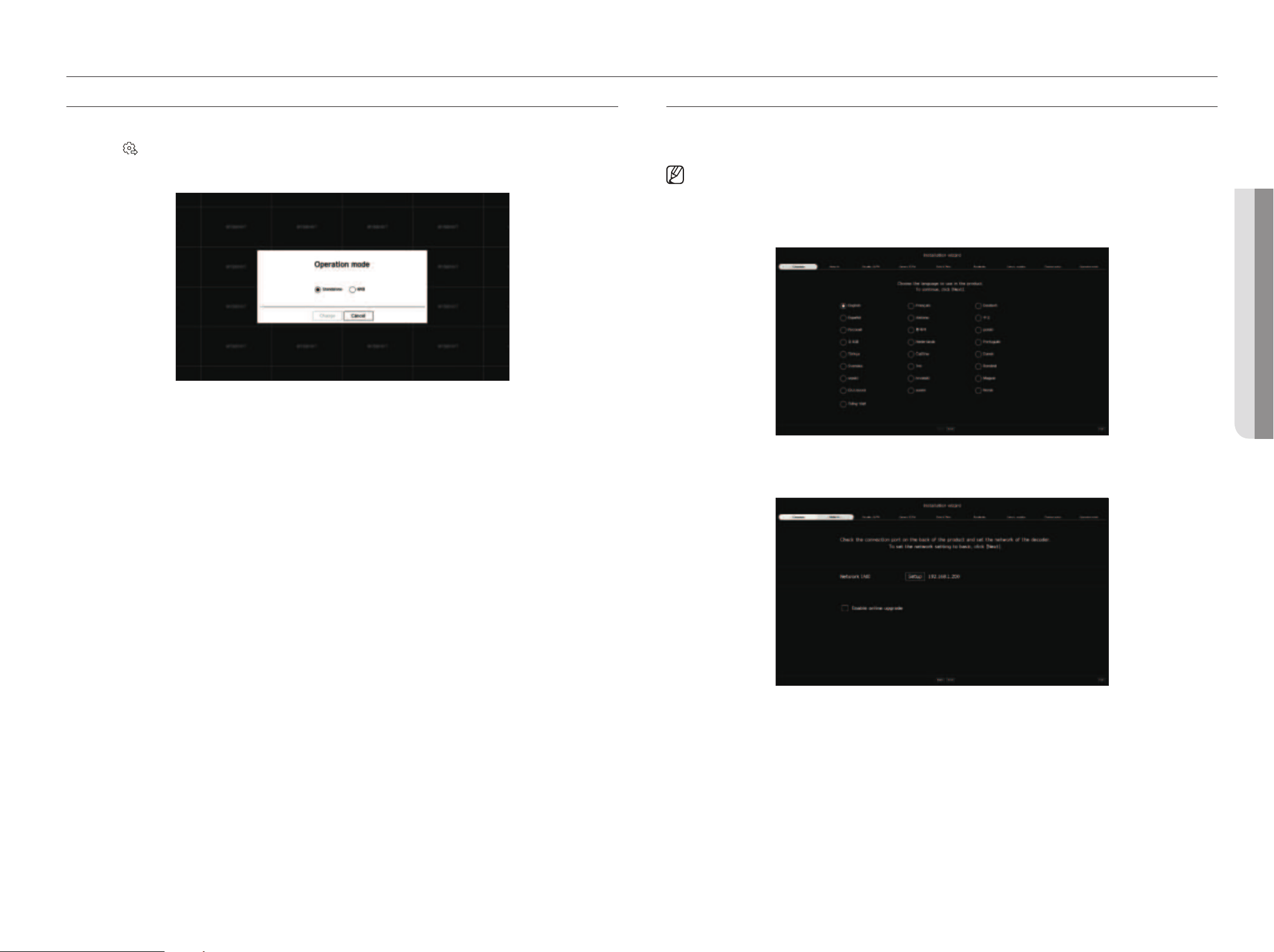
1. On the <language> screen, select the language and press the <Next> button.
2. Set the network connection type and the connection environment on the <Network> screen, and then click the
<Next> button.
Setting up the Network
●
Network (All): Can be used as a common port for the camera and web viewer connection.
●
Setup
– IP type: Allows you to select the type of network access.
– IP address, Subnet mask, Gateway, DNS
■
Manual: The IP address, subnet mask, gateway, and DNS can be entered manually.
■
DHCP: The IP address, subnet mask, gateway, and DNS can be automatically set.
Online Upgrade
You can receive new firmware notifications when the decoder connects to a network.
SETTINg ThE SySTEm OpERATION mODE
If you have admin permissions, you can select operation mode to control the decoder.
1. Select
<
>
at the top right of the screen.
2. The <Operation mode> settings window will appear.
3. After selecting the desired operation mode, click <Change>.
●
Standalone: Can control Live monitoring and changes to the settings of the camera on a decoder.
You can only change admin account information and operation mode in the web viewer.
●
WEB: Can only Live monitor the camera on a decoder, and you need a web viewer to change the settings or
control.
4. If you change the operation mode, the decoder restarts and the set layout is initialized.
14_ getting started
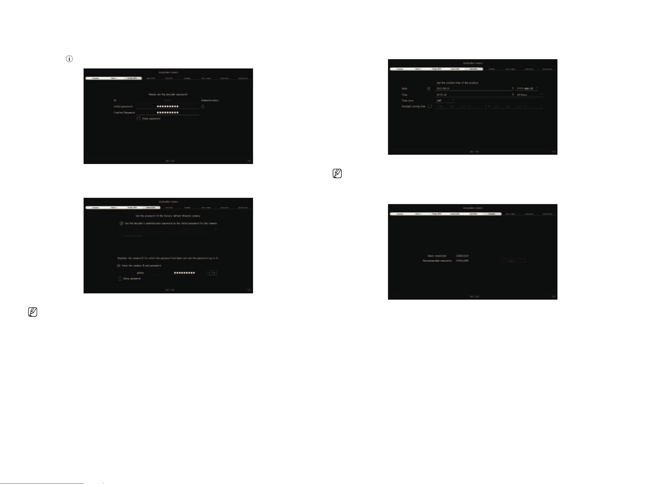
3. Set the administrator password on the <Decoder ID/pW> screen and click the <Next>.
If you click <
>, a basic guide for password setup is displayed. Refer to the password setup rules.
4. Set the camera password in factory default status on the <Camera ID/pW> screen.
If ID/PW is already set in the camera, register the ID/PW and click <Next>.
■
When the password is in factory default status, it can be changed and managed in a batch.
■
Up to 3 sets of camera IDs with passwords and passwords can be registered.
■
You may change the passwords of registered cameras all at once on the “Setup > Camera > Camera password” menu.
■
You cannot change the password for cameras registered with ONVIF and RTSP.
5. Set the date, time, time zone, and daylight saving time on the <Date & Time> screen, and then click <Next>.
■
Depending on the location of the product release, the standard time zone setup may vary.
6. To set the recommended resolution on the <Resolution> screen, click <Apply> followed by the <Next> button.
English _15
• gETTINg STARTED
getting started
• gETTINg STARTED
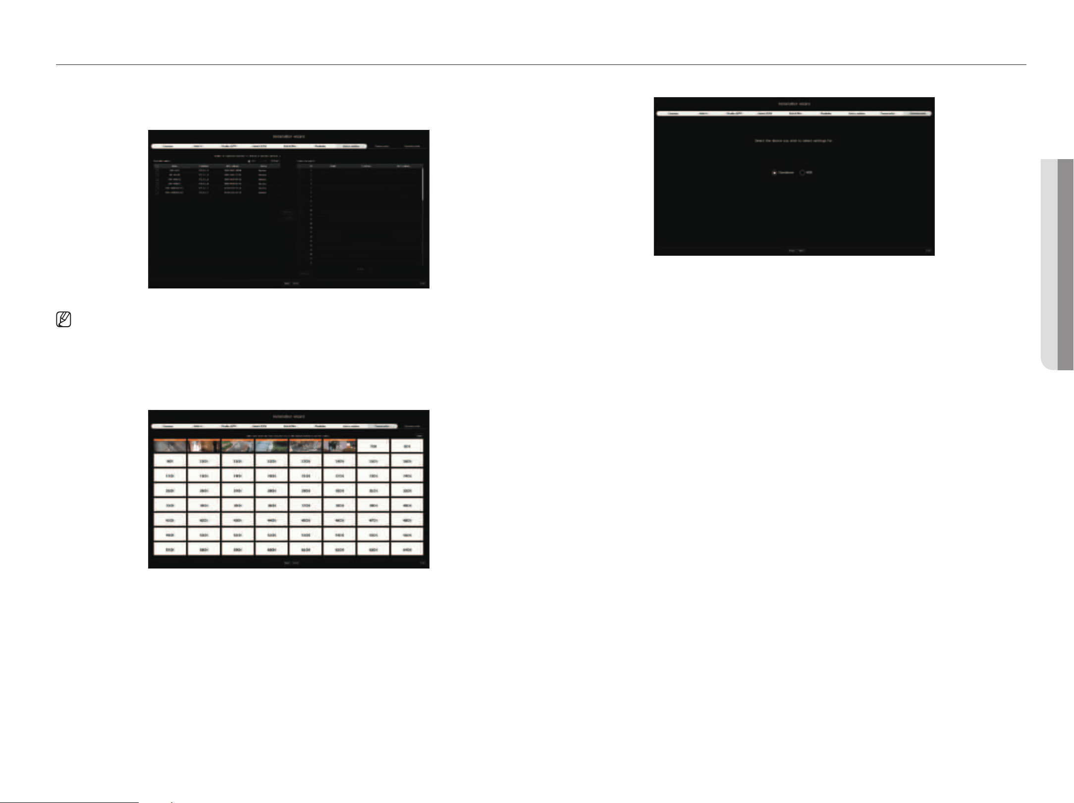
7. On the <Camera register> screen, select a camera to register from the searched camera list and click <Register>.
Select a camera to register from the list and click <Change Ip>.
After completing camera register click <Next>.
■
The operation will become available after entering the set ID and password for the camera and completing the connection test.
8. On the <Channel setup> screen, you can view the camera videos registered to each channel in thumbnails along
with thumbnail information. To change the camera video position, select a video and drag and drop it to the desired
location.
After completing channel setup, click <Next>.
9. Select an operation mode that can control the decoder from the<Operation mode> screen.
●
Standalone: Can control Live monitoring and the setting changes of the camera on a decoder.
You can only change admin account information and operation mode in the web viewer.
●
WEB: Can only Live monitor the camera on a decoder, and you need a web viewer to change the settings or
control.
10.
Click <finish> to complete the installation wizard.
16_ getting started
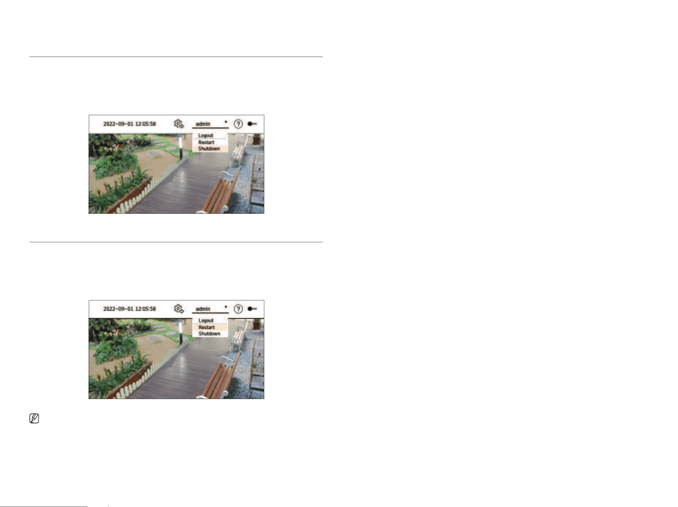
ShUTTINg DOWN ThE SySTEm
1. Select
<Shutdown>
in the top right of the screen.
2. The <Shutdown> confirmation pop-up window will appear.
3. Click
<
Ok
>
.
The system will shut down.
RESTARTINg ThE SySTEm
1. Select <Restart> at the top right of the screen.
2. The
<
Restart
>
confirmation pop-up window will appear.
3. Click
<
Ok
>
.
The system will restart.
■
Only users with the "Restart/Shutdown" permission can shut down or restart the system.
■
For more information on permission setup management, see the "Setup > Setting the System > User” page in the table of contents.
English _17
• lIVE
live
• lIVE
You can check the video of cameras connected to the decoder. Also, you can adjust the camera and check the network
transfer status.
■
You can check the following Live screen configuration when it is in <Standalone> operation mode.
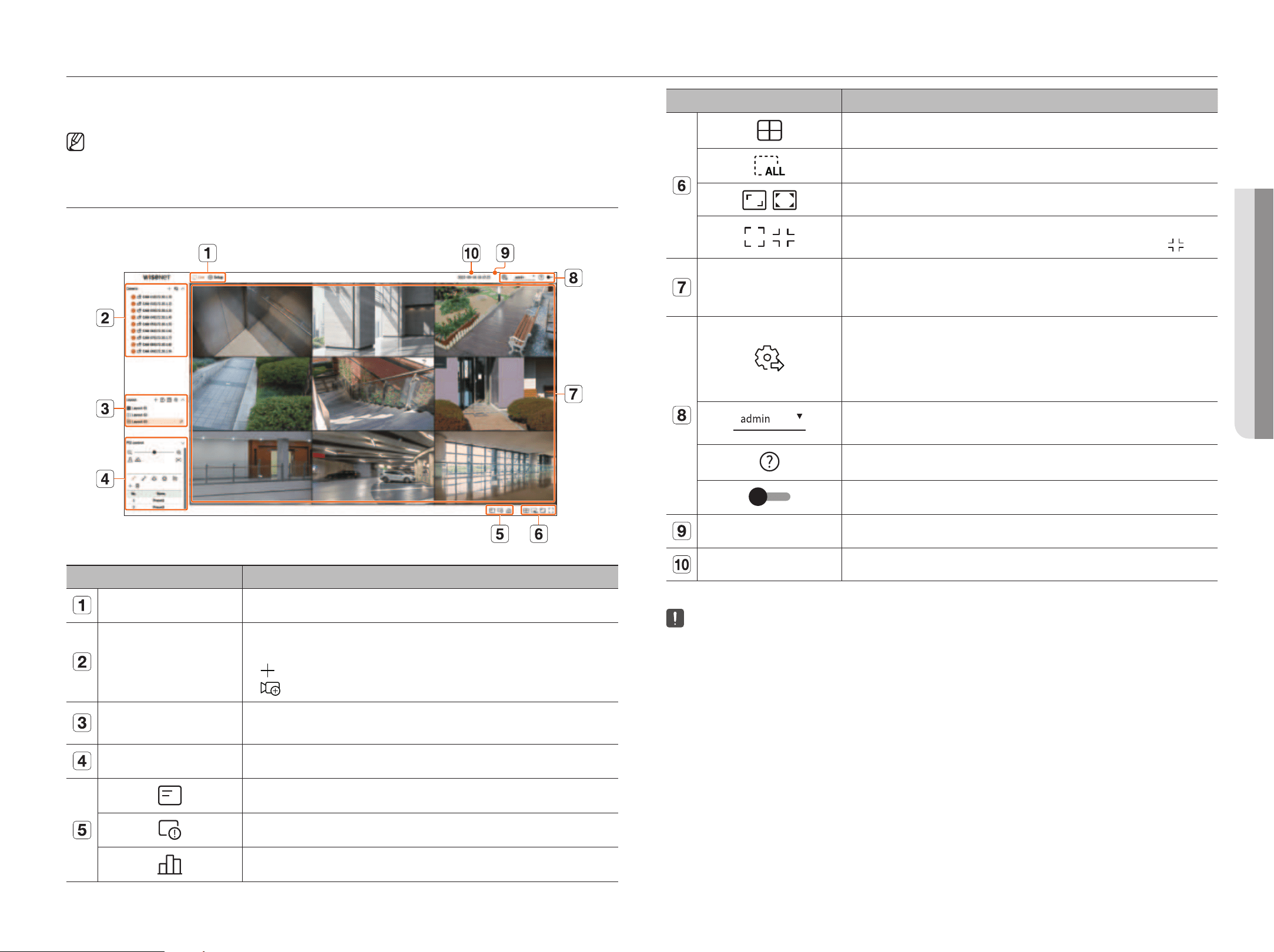
SCREEN lAyOUT Of ThE lIVE
The live screen is built as follows.
Name Function Description
Menu Clicking on each menu takes you to the corresponding menu screen.
Camera List
The list of cameras registered to the decoder is displayed.
You can also register the camera manually or automatically.
●
: Registers the camera manually.
●
: Searches and registers the camera connected to the decoder automatically.
Layout List
This displays a list of the default layouts and the layouts that have been created.
You can also set and play a sequence of layout lists.
PTZ control Controls the PTZ camera connected to the decoder.
Displays the information on the OSD screen in the video window.
Shows channel information.
Shows the status of all cameras connected to the decoder.
Name Function Description
Sets the split screen of the video window.
Removes all screens from the video window.
/
Shows the video in its original aspect ratio or full-screen.
/
It changes to full screen from the current split mode.
To exit full screen, place your mouse cursor over the bottom of the full-screen mode and click <
>.
Video window
Shows the video of cameras connected to the decoder.
●
You can change to a single screen by double-clicking the desired video in Split mode.
●
If you double-click the video in single screen, it will change to split screen.
If you have admin permissions, you can select operation mode to control the decoder.
●
Standalone: Can control Live monitoring and the setting changes of the camera on a decoder. You can only
change admin account information and operation mode in the web viewer.
●
WEB: Can only Live monitor the camera on the decoder, and requires the web viewer to change settings or
control.
The ID of the connected user is displayed.
The <Logout/Restart/Shutdown> menu will appear if you click it.
Displays a QR code for downloading the user manual.
Changes the color theme of the screen.
System Status Display Displays the status of the system or network.
2022-09-16 16:17:25 Displays the current time and date.
■
If you set the camera frame rate to 60 fps, the frame rate may decrease on the Live screen depending on the monitor resolution output.
18_ live
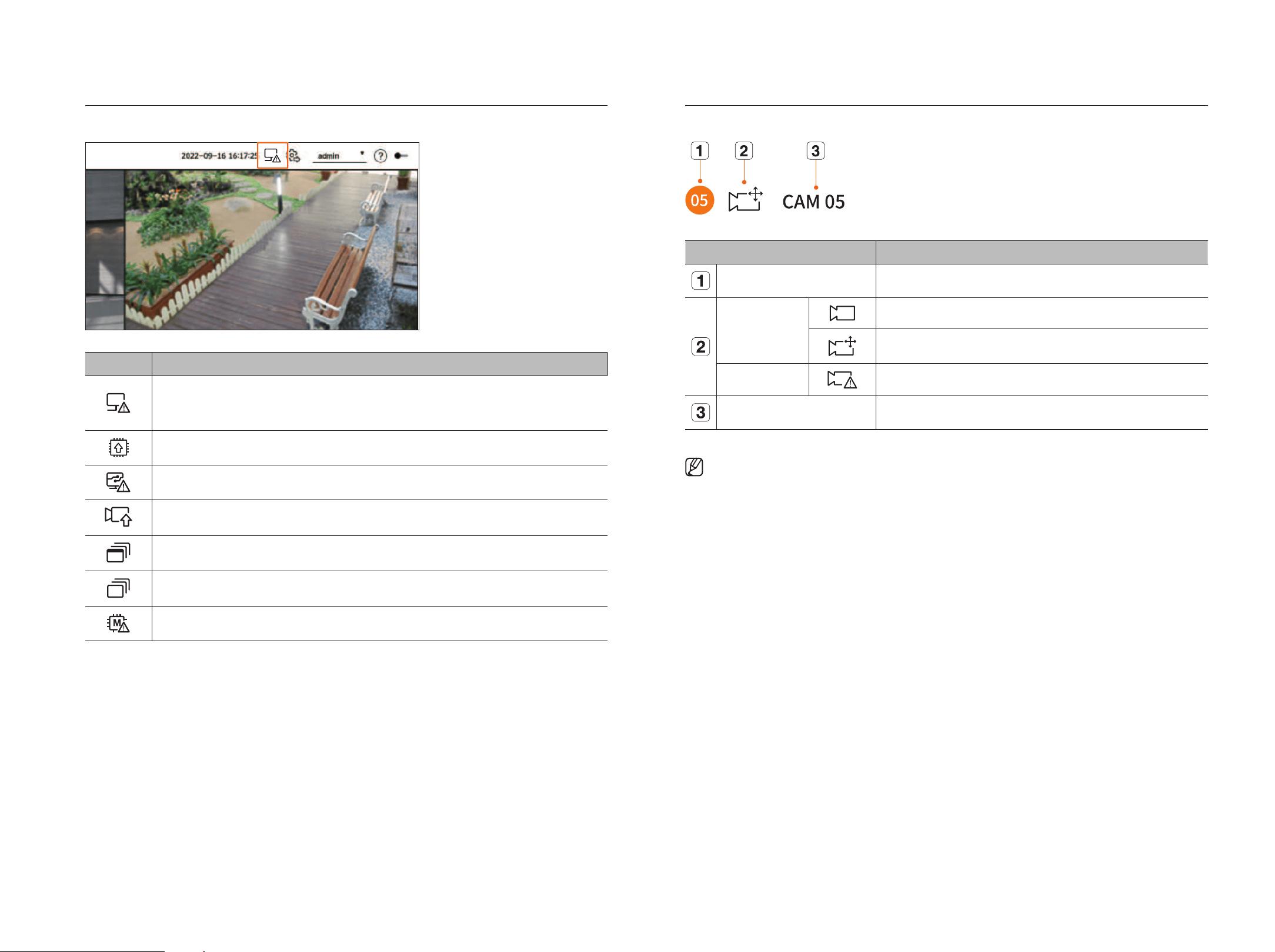
Checking the System Status
The icon at the top of the screen indicates the status of the system.
Name Function Description
Displayed when a network overload occurs.
■
Displays when there is an excessive CPU load and the reception performance has been exceeded. It disappears when you modify
the Delete Camera or Set Camera to reduce the data rate.
Displayed if the server has firmware to update.
It is displayed when the system is overloaded.
Displays and disappears when the camera firmware update is completed.
Displayed when playing the layout sequence.
Displayed when running automatic switching of the split screen.
Displayed when an error occurs in the internal memory.
Checking the Camera list
Displays the camera type, status, and name registered in the decoder.
Name Function Description
Channel information Displays channel information. (channel number, color indication on video window assignment).
Camera type
Displays a normal camera.
Displays a PTZ camera.
Camera status
Displays the camera error status.
Camera name Displays the name set for the camera.
■
If a camera connection error occurs, it is disabled in the list.
■
The camera status displays information changes according to the network connection status and settings.
English _19
• lIVE
live
• lIVE
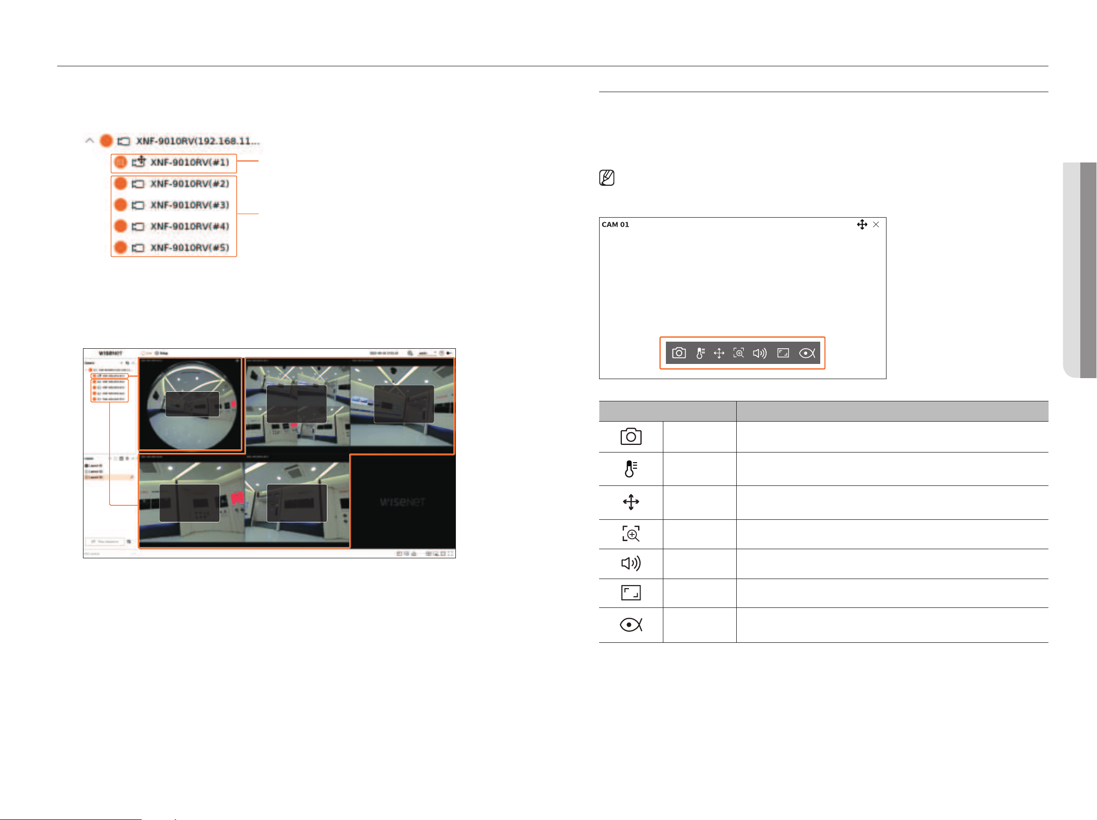
Check multichannel Cameras list
For multichannel cameras registered with the Wisenet protocol, the channel information will be displayed under
the model name of the multichannel camera.
Registered channel
Unregistered channel (virtual channel)
In the case of a multichannel camera in the <Standalone> operation mode, register only one main channel.
Subchannels can be monitored in real-time without being registered in the decoder.
Real-time monitoring is available when the desired channel to monitor is registered in the <WEb> operation
mode.
Registered
channel
Unregistered
channel
(Virtual channel)
Unregistered
channel
(Virtual channel)
Unregistered
channel
(Virtual channel)
Unregistered
channel
(Virtual channel)
live Screen menu
After selecting the desired channel on the split mode, roll the mouse cursor over the screen to see the live screen
menu.
The Live screen menu appears differently depending on the decoder operation status or the type of the
registered camera.
■
Each function may be restricted depending on the type of camera and the user's authority.
■
For more detailed information about each function, refer to the table of contents “Live > Camera Video Control".
Menu title Functions
Capture You can take a screenshot of the selected channel.
Temperature
detection
For images that support the thermal imaging camera function, you can click the desired point to check
the temperature information.
PTZ control
If the network camera connected to the selected channel supports the PTZ function, it changes to the PTZ
control mode.
Zoom in You can zoom in or zoom out the video.
Audio Turns the audio on or off when the audio is connected.
Channel aspect ratio Shows the video in actual proportions.
Dewarping
Enters the setup mode for dewarping the fisheye camera.
■
It works only when the video resolution is 1:1. Some models do not support this function.
20_ live
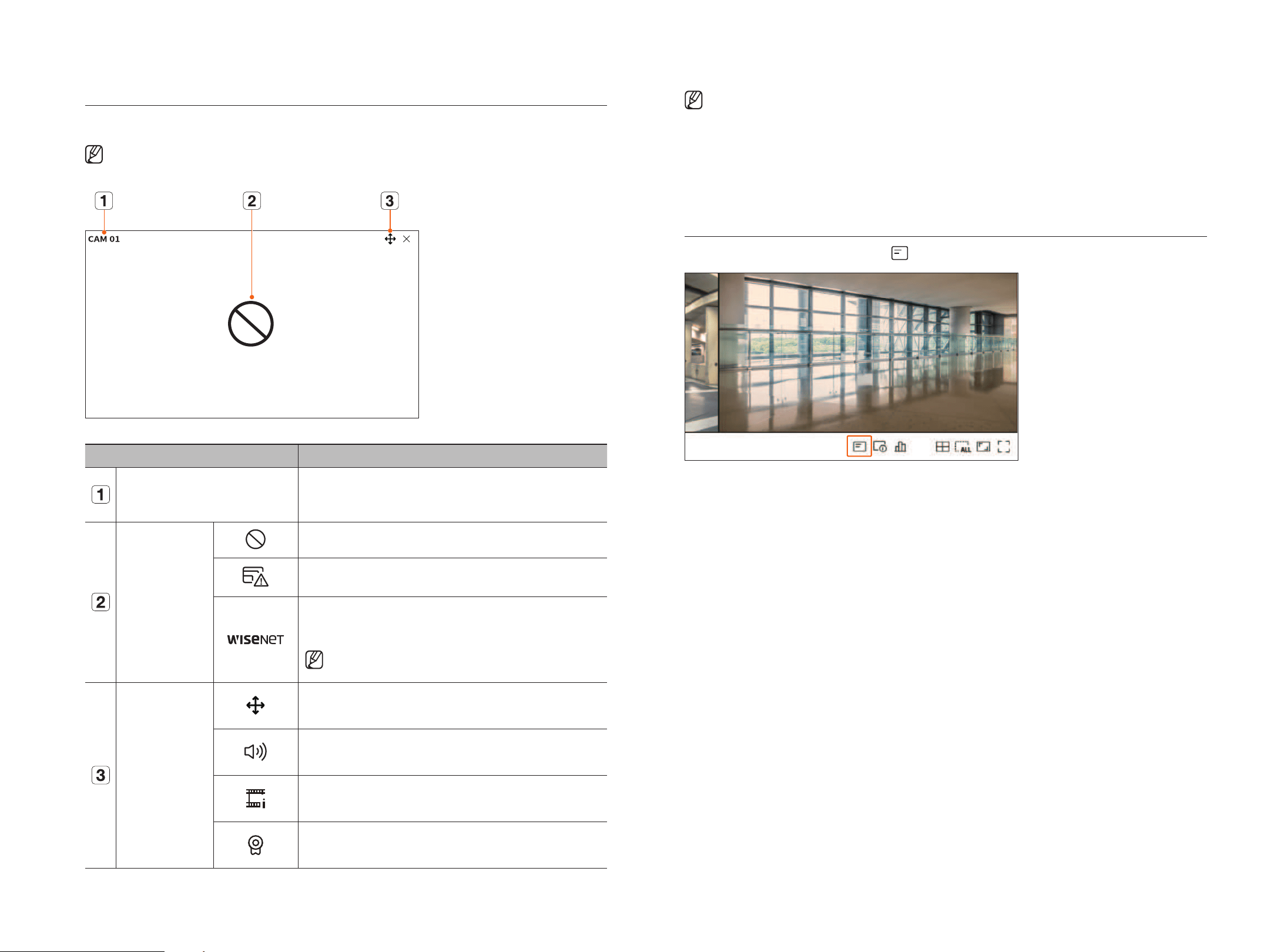
Icons on the live Screen
You can check the status or operation with the icons on the live screen.
■
The icons displayed on the screen may differ depending on the type of camera and the user's authority.
Menu title Functions
Camera name
Displays the camera name.
●
For multichannel cameras, the channel number is displayed. The channel number may not
be displayed depending on the camera.
Video input status
It is displayed when there is no input while the camera is
on
.
Displayed when the resolution of the live video exceeds the supported range while the
camera is
on
.
Displayed when the camera is not registered.
If you set the channel setup to <Covert 2>, nothing will be displayed on the Live screen.
■
If you set it to <Covert 1>, the video will not be displayed on the Live
screen, and only the OSD will be displayed.
Status Display
It is displayed on the channels that can enable the PTZ mode.
Displays audio On/Mute.
It will not be displayed when <Off> is selected for the audio in the channel setup.
It is displayed when it fails to decode all the frames due to limited decoding performance
and in this case, only the I-Frame is decoded.
Displayed if the Wisenet camera's certificate is valid.
■
The 'Live4NVR' profile is added automatically with network camera auto registration, and settings can be changed according to the user
environment.
■
Depending on camera specification, you may not be able to add a profile or if you have the PLUGINFREE profile, you will not be able to add the
Live4NVR profile.
■
When the system is overloaded and the performance is down, the network camera may play only the main frame(I-frame).
■
To set profiles, see the "Setup > Setting the Camera > Profile setup” page in the table of contents.
OSD Information Display
To show or hide the OSD information, click <
> at the bottom of the screen.
English _21
• lIVE
live
• lIVE
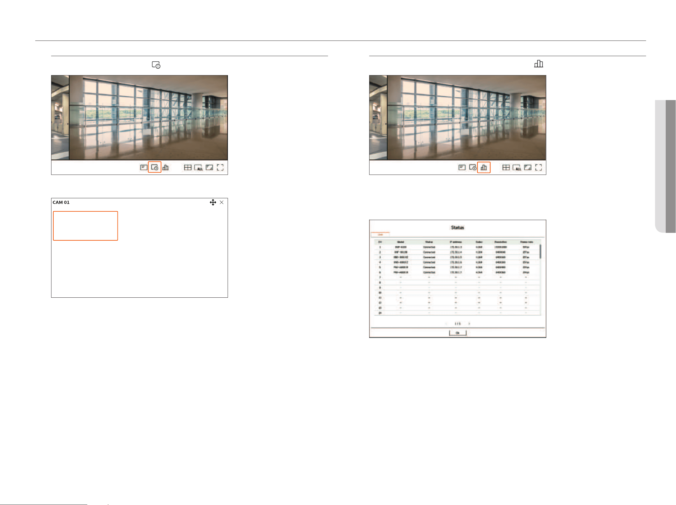
Channel Information Display
To check the channel information, click <
> at the bottom of the screen.
The information of the current video is displayed on the live video which is being monitored.
800x448 (H.264)
S/I/D 25/24/24
XNV-6081Z(S)
●
800x448: Displays the resolution of the video.
●
H.264: Displays the video codec.
●
S/I/D 25/24/24: Displays the frame rate (FPS) of the video. (S: Settings, I: Video input, D: Video display)
●
XNV-6081Z: Displays the camera model name.
●
S: Displays the protocol used when registering the camera.
– S and V represent the Wisenet protocol while O represents ONVIF.
– When connected by the RTSP protocol, only RTSP is displayed without the product name.
Checking the Camera Status
To check the status of all cameras connected to the decoder, click <
> at the bottom of the screen.
Checking the live Status
You can check the status and transmission information of the network camera connected to each channel.
●
Model: Displays the model name of camera connected to each channel.
●
Status: Shows the connection status of the camera set to each channel.
●
IP address: Displays the IP address of a camera set to each channel.
●
Codec: Displays the live profile codec information for a camera set to each channel.
●
Resolution: Displays the live profile resolution of a camera set to each channel.
●
Frame rate: Displays the live profile transmission rate for a camera set to each channel.
22_ live
Channel Setting
You can display the channel in a desired area of a split screen.
To switch the position of a channel, hold a channel and drag and drop it to the desired location.
Example) If switching Ch 1 to Ch 7
CH15
CH11
CH16
CH12
CH7
CH3
CH8
CH4
CH13
CH9
CH14
CH10
CH5
CH1
CH6
CH2
CH15
CH11
CH16
CH12
CH1
CH3
CH8
CH4
CH13
CH9
CH14
CH10
CH5
CH7
CH6
CH2
Switching to Single mode
When in split mode, select and double-click the desired channel to switch to its Single mode.
Example) If double-clicking Ch 3.
CH15
CH11
CH16
CH12
CH7
CH3
CH8
CH4
CH13
CH9
CH14
CH10
CH5
CH1
CH6
CH2
CH3
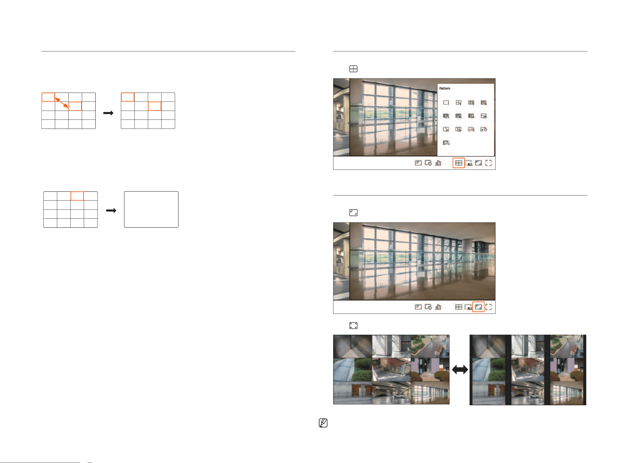
Change Split mode
You can change the split mode of the screen.
Click <
> at the bottom of the screen to select the desired split mode.
Change Overall Aspect Ratio
Video screen ratio for all channels can be changed in live split screen mode.
Click <
> at the bottom of the screen. It changes to the actual proportion of the video.
Click < > to return to the previous aspect ratio.
■
You can change the aspect ratio of each channel. For more information, refer to the table of contents “Live > Camera Video Control > Change
Channel Aspect Ratio."
English _23
• lIVE
live
• lIVE
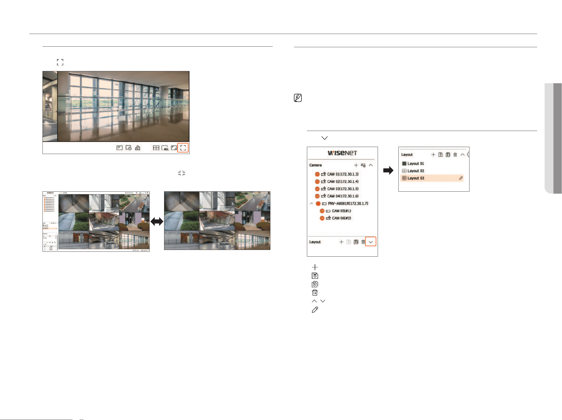
full Screen mode
You can change to full screen mode, which has no top/bottom/left/right areas of the live screen.
Click <
> at the bottom of the screen.
Changes to full screen mode.
■
To exit full screen, place your mouse cursor over the bottom of the full screen and click < >.
general mode full screen mode
lAyOUT SETUp
This section outlines how to select a series of channels based on their purpose/accessibility and monitor them in a
single layout.
Example) Layout "Lobby" - Lobby camera 1, Lobby camera 2, Front entrance camera 2
Layout "VIP" - Directors' meeting room 1, Directors' meeting room 2, Directors' lounge 1, Corridor camera on
the 7th floor
■
After the software upgrade, the previously set layout may be changed. Reset the layout and sequence.
■
When changing the operation mode, all set layouts are initialized. Reset the layout and sequence.
Checking layout list
Click < > from the <layout> item to see the layout list.
●
: Create a new layout.
●
: Save the changed layout.
●
: Saves the selected layout with a different name.
●
: Delete the added layout.
●
/ : Open or close the layout list.
●
: Change layout name.
24_ live
Add layout and Set Name
1. Click <
> to add a layout.
2. Click <
> to set the name for the added layout.
3. Double-click or drag and drop a channel from the camera list to display it on the layout screen. The selected
channel will be displayed in the video window.
■
You can simultaneously assign multiple continuous channels from the camera list to the video window. Drag the desired channels from the camera
list and drop them in the video window. Depending on the drop location and the number of channels, the empty area or the current layout will be
expanded to assign the video.
4. Click <
> to save the set layout.
■
Each layout is saved separately by the user.
Delete layout
Click <
> after selecting the layout to delete.
■
You cannot delete the default layout.
Change of layout Channel and Name
1. Click <
> after selecting a layout.
2. Add or delete channels or rename layouts.
3. Click <
> to save the changed settings.
Dynamic layout
You can set the size and position of the video assigned to the layout as desired.
■
The dynamic layout function can only be set on the primary monitor.
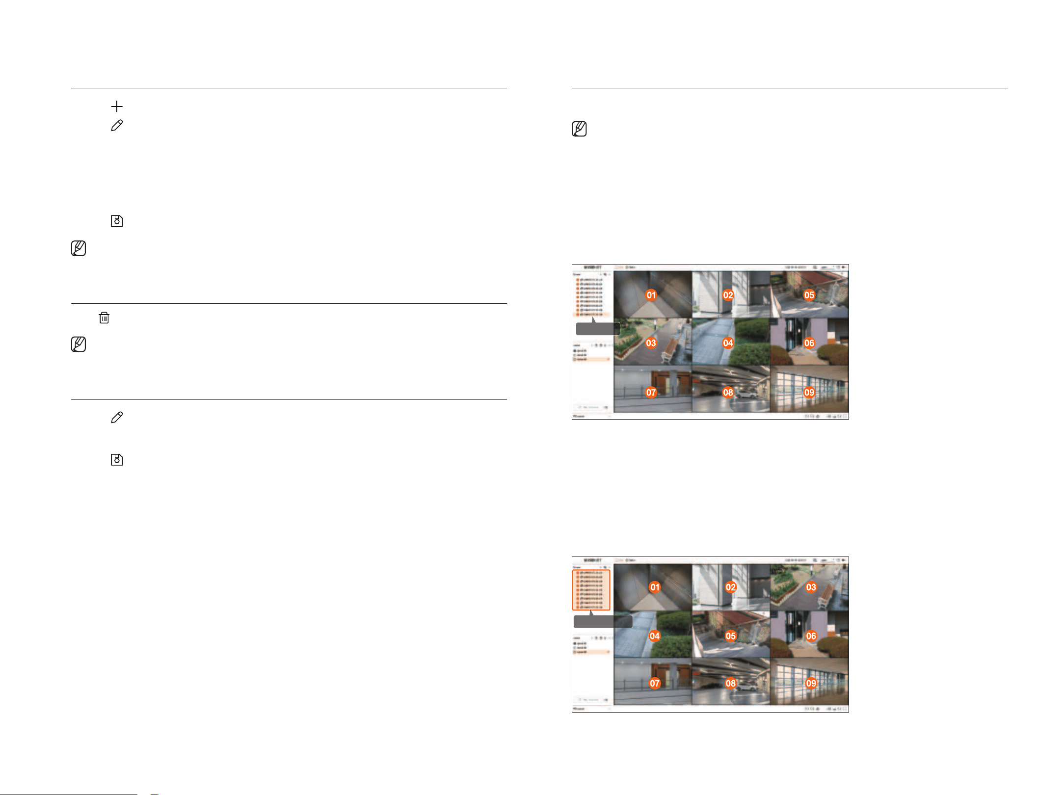
Assigning One Channel
Double-click or drag and drop a channel from the camera list to display it on the layout screen.
The video is assigned to the empty area or depending on the drop location, the current layout will be expanded
to assign the video.
Example) When assigning 9 channels to a new layout, the channels are arranged in the order below.
Double-click
Assigning multiple Channels at once
Drag the continuous channels from the camera list and drop them in the video window.
Depending on the drop location and the number of channels, the empty area or the current layout will be
expanded to assign the video.
Example) When assigning 9 consecutive channels to a new layout, the channels are arranged in the order
below.
Drag and drop
English _25
• lIVE
live
• lIVE
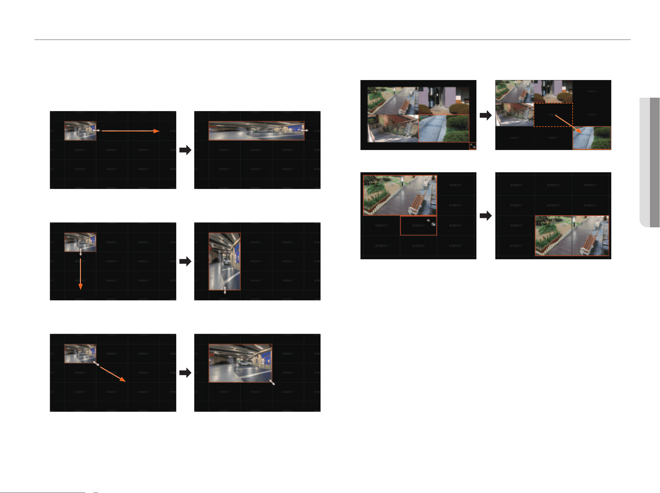
zooming In and Out of Videos
You can zoom in or out of the video by dragging a corner or vertex of the video in the desired direction.
If you double-click the corner or vertex of the zoomed in video area, the video will be zoomed out incrementally.
The video can be zoomed in if there is an expandable blank area around the video.
horizontal zoom
Vertical zoom
Diagonal zoom
moving Videos
To move the video, click the video and then drag and drop it in the desired location.
Dragging it outside of the layout area will extend the layout area.
The enlarged video can be moved only when there is an empty area that is the size of the video.
26_ live
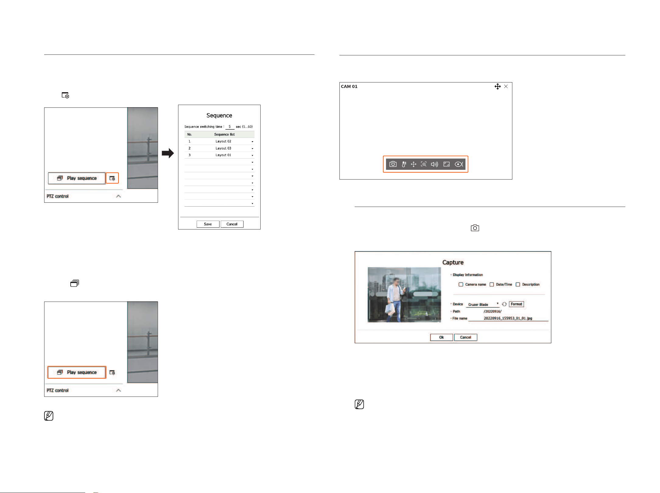
play layout Sequence
You can automatically switch the layout list to a set time interval to view.
Sequence Setting
Click < > at the bottom of the layout list to set the sequence.
●
Sequence switching time: Set the switching time of the layout list.
●
Sequence list: Set the layout sequence playback order. You can add the same layout repeatedly.
play layout Sequence
Click the <
play sequence> on the bottom of the layout list to change the layout automatically according to
the sequence settings.
■
The <Play sequence> is activated only when the sequence is set up.
CAmERA VIDEO CONTROl
By using the function icon of the video window, you can easily use the functions of capture, video zoom, PTZ camera,
and thermal imaging camera. When you place your mouse over the video window, the live screen menu will appear.
Capture
You can take a screenshot of the current video of a specific channel selected on the live screen.
1. Select a channel to capture video and click <
>.
2. Select the output information to be displayed on the captured screen.
3. Set the device where the screenshot file will be saved and the file name.
■
If you click <Format>, the format confirmation window will appear. Click on the <Yes> button to format the selected storage device.
4. Complete the settings and click <Ok>, then the image captured from the screen will be saved to the selected
device.
■
Camera screen larger than 2 megapixels is captured in Full HD size.
English _27
• lIVE
live
• lIVE
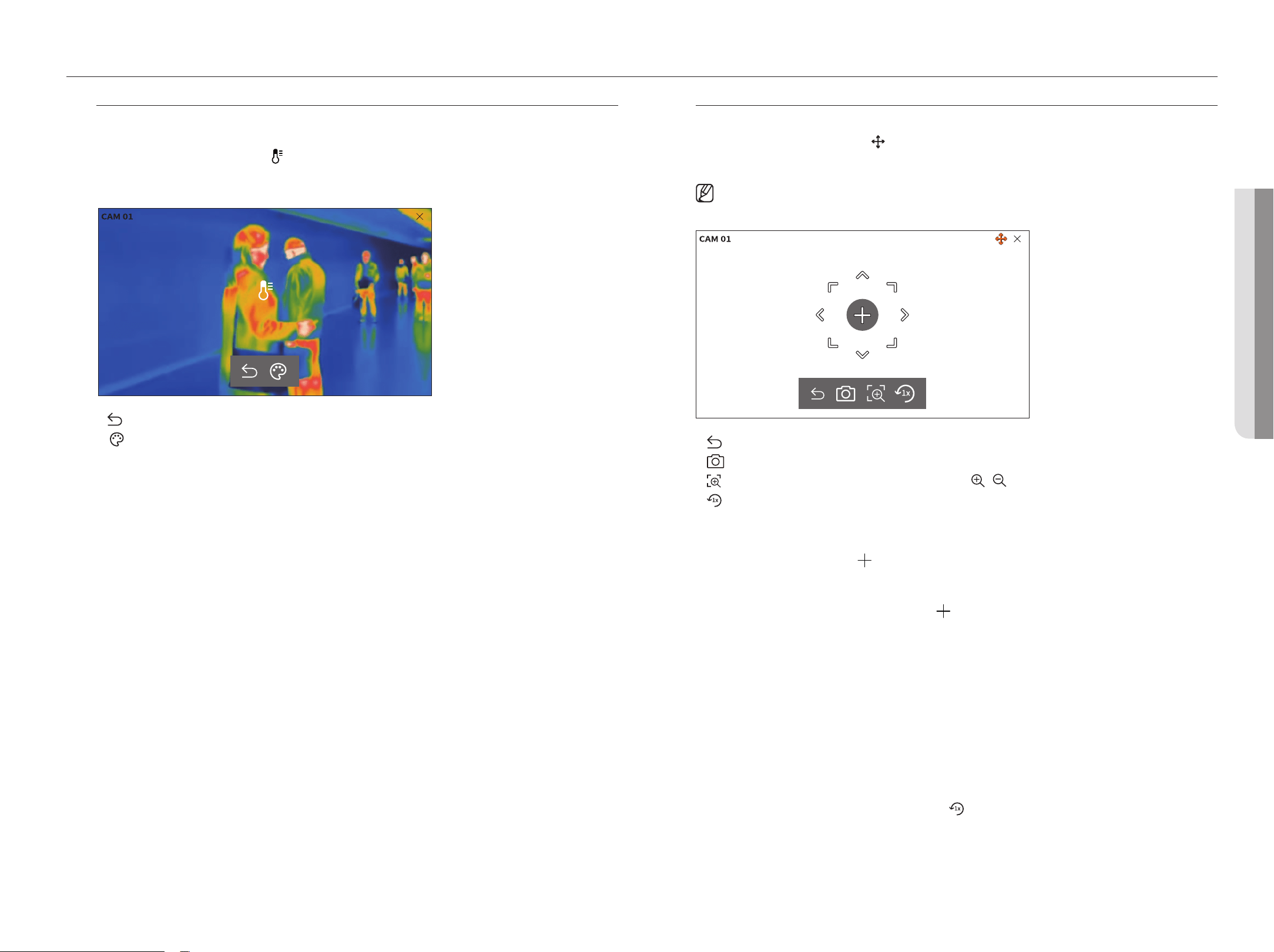
Temperature Detection mode
For images that support the thermal imaging camera function, you can click the desired point to check the
temperature information.
Select the desired channel and click <
>.
When you place your mouse over the video, the mouse pointer changes to a thermometer shape, and when you
click a specific location on the video, the temperature at that location is displayed next to the mouse pointer.
36.5°
●
: Exits temperature sensing mode.
●
: The color of the video changes according to the temperature color selection.
pTz mode
You can run PTZ control of the selected channel.
Select the desired channel and click <
>.
Enters the PTZ control mode.
■
Depending on the camera, the PTZ control function and speed may be different.
●
: The PTZ mode is closed.
●
: Captures video of the current state.
●
: After clicking the digital zoom icon, you can use the < / > buttons to zoom the video in or out.
●
: Returns to the 1x zoom screen.
Adjusting the Camera Direction
When you roll over the mouse to <
>, the 8-way key appears, and when the mouse leaves the area of the
direction key, the direction key disappears. You can fine-tune the camera direction by clicking the 8-direction key
once. Keep clicking the arrow keys to move in the desired direction and release the mouse to stop.
To quickly adjust the direction of the camera, click <
> and drag. The screen moves quickly in the desired
direction. You can adjust the screen movement speed according to the drag distance.
moving to the Center of the Screen
Click a specific location on the screen to move the video at that location to the center of the screen.
zooming the Selected Area
Drag a specific area of the screen to move the selected area to the center of the screen and zoom in.
zooming In and Out of Videos
You can zoom in or out using the mouse wheel. Click <
> to go back to the original size.
28_ live
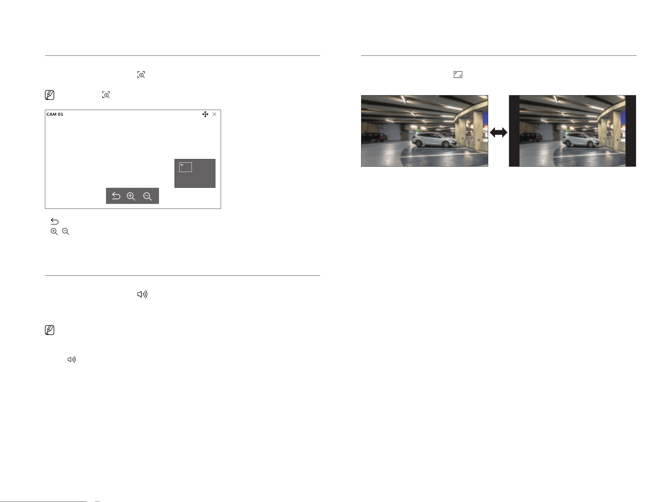
zoom in
You can zoom in or out the video via digital zoom.
Select the desired channel and click <
>.
Enters the digital zoom mode.
■
In PTZ mode, click <
> to run the digital zoom.
●
: Exits the digital zoom mode.
●
/ : Zooms in or out of the video.
●
Minimap: When the video is zoomed in by 10%, a minimap is displayed. You can quickly check the desired
location in the enlarged video through the minimap.
Audio
You can turn the sound on/off corresponding to the channel in Live mode.
Select the desired channel and click <
>.
Audio output can only be turned on in one channel. The audio output of other channels will be automatically
turned off.
■
If you have configured the audio output settings properly but the audio or voice is not output, check if the connected network camera supports
the sound signal and if you have configured the sound settings as appropriate.
The sound icon can be displayed if the sound signal fails to output from noise.
■
Only the channel where the <Audio> is set to <On> in “Setup > Camera> Channel setup” menu displays the audio icon
( ) in Live mode that you can use to turn the sound on or off.
Change Channel Aspect Ratio
You can change the aspect ratio of each channel.
Select the desired channel and click <
>.
It changes to the actual proportion of the video.
English _29
• lIVE
live
• lIVE
Dewarping
You can correct distorted images from the fisheye camera.
Select the desired channel and click <
>.
You will enter the setup mode for dewarping.
■
This function is not supported in some models.
■
This works only when the video resolution is 1:1.
■
The set dewarping mode is cleared when the layout is changed, so set it again.
■
Dewarping will be applied only to the selected channel.
■
In dewarping mode, the frame rate of the video is limited depending on the resolution. (3 fps - 30 fps)
●
: Dewarping mode is closed.
●
: You can select from among <Single>, <Quad view>, <Single panorama>, and <Double panorama> for
the view mode.
– Single, Quad view: You can use the PTZ function by dragging the mouse up, down, left, and right or by using
the mouse wheel.
– Single panorama: You can select this when the mounting mode is <Wall>.
– Double panorama: You can select this when the mounting mode is <ground> or <Ceiling>.
You can use the PAN function by dragging the mouse left and right.
●
: You can select the mounting mode from <ground>, <Wall>, and <Ceiling>.
pTz CONTROl
With this decoder, you can configure the settings of PTZ cameras aside from general security cameras to users'
preferences.
This is active only if a channel that a PTZ camera is connected to is selected.
getting Started with pTz Operations
The PTZ camera will be activated only if the channel of the PTZ camera is selected. After selecting the desired
channel, click <
> on the live screen menu.
■
This is available only if a PTZ camera is connected and the < > icon is displayed on the screen.
■
Even if the connected network camera does not support the PTZ operations, you can configure the PTZ control settings (if possible) by installing
the PTZ driver (physical device).
■
It only supports a network camera with Hanwha Techwin's PTZ function and a camera registered in the ONVIF.
pTz Control menu
You can use a single camera to perform the Pan, Tilt, and Zoom operations to monitor multiple places, and
configure the custom settings of the presets in the desired mode.
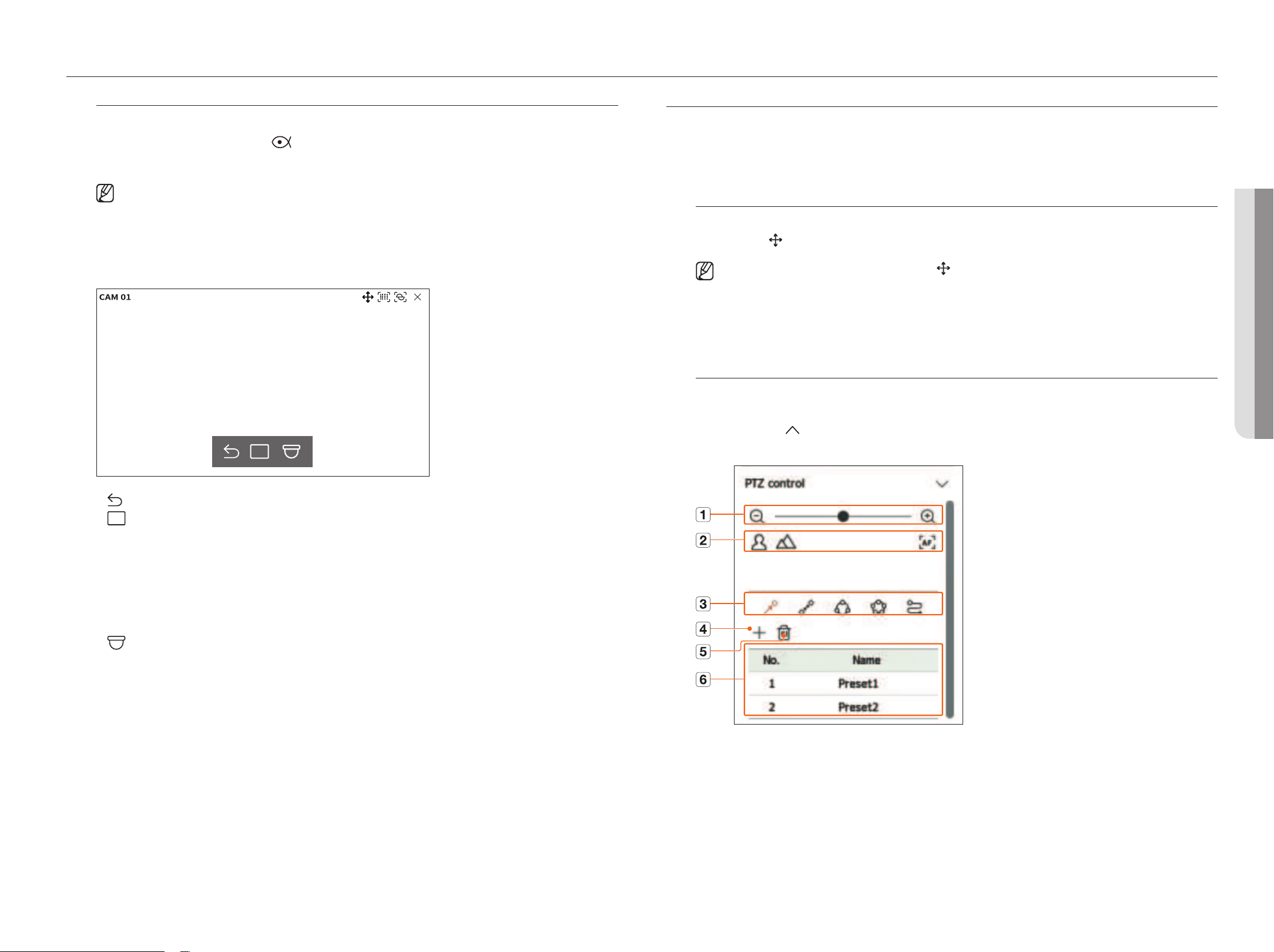
Click <pTz control
> on the bottom left of the Live screen to display the PTZ camera control menu as shown
below.
30_ live
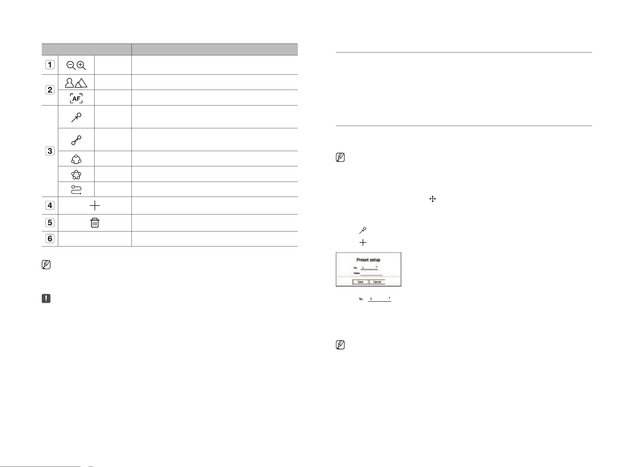
Name Functions
Zoom out/
Zoom in
Activate the Zoom operation of the PTZ camera.
Near/Far You can adjust the focus manually.
Auto focus You can adjust the focus automatically.
Preset
Set the preset position to move the camera, and then select the desired preset to move to the set
position.
Swing
Swing is a monitoring function that moves between two preset points and enables you to trace
the motion.
Group The group function enables you to group various presets before calling them in sequence.
Tour Monitor all the groups created by a user in turn.
Trace Trace remembers the trace of movements that you instructed and reproduces it for your reference.
The preset you set is saved and displayed in the list.
Deletes the selected preset list.
Preset List Shows a list of saved presets.
■
The PTZ working (active) mark can be active even if the PTZ operation is not operating normally. So ensure that you have completed the PTZ
settings before proceeding.
■
The names and functions of Swing, Group, Tour, and Trace may differ in some cameras.
■
Even if your network camera supports the function, you can use it only if the button is activated in the PTZ control launcher.
Using Digital pTz (D-pTz) function
1. Register a camera that supports the D-PTZ profile.
■
In cameras that support the D-PTZ profile, you can use the D-PTZ function.
2. Both cameras that support general PTZ and cameras that support D-PTZ can control the live image using
some of the <pTz control> function menus.
■
For more information about the supported functions, please refer to the camera manual.
preset
A preset is a set of saved data specifying the locations of a PTZ camera. A single PTZ camera can save up to 300
locations.
■
The max. number of presets may vary depending on the number of presets supported by the camera.
To add a preset
1. Select the desired channel and click <
>.
■
The PTZ control screen appears.
2. Use the arrow keys to adjust the camera to the point.
3. Click <
>.
4. Click <
> to go to the "preset setup" window.
5. Click < > to select the preset number to set.
6. Enter the preset name.
7. Click <Save>.
The preset setting will be saved.
■
If you replace a camera that saves your preset settings with a different one, you must configure the preset settings again.
English _31
• lIVE
live
• lIVE
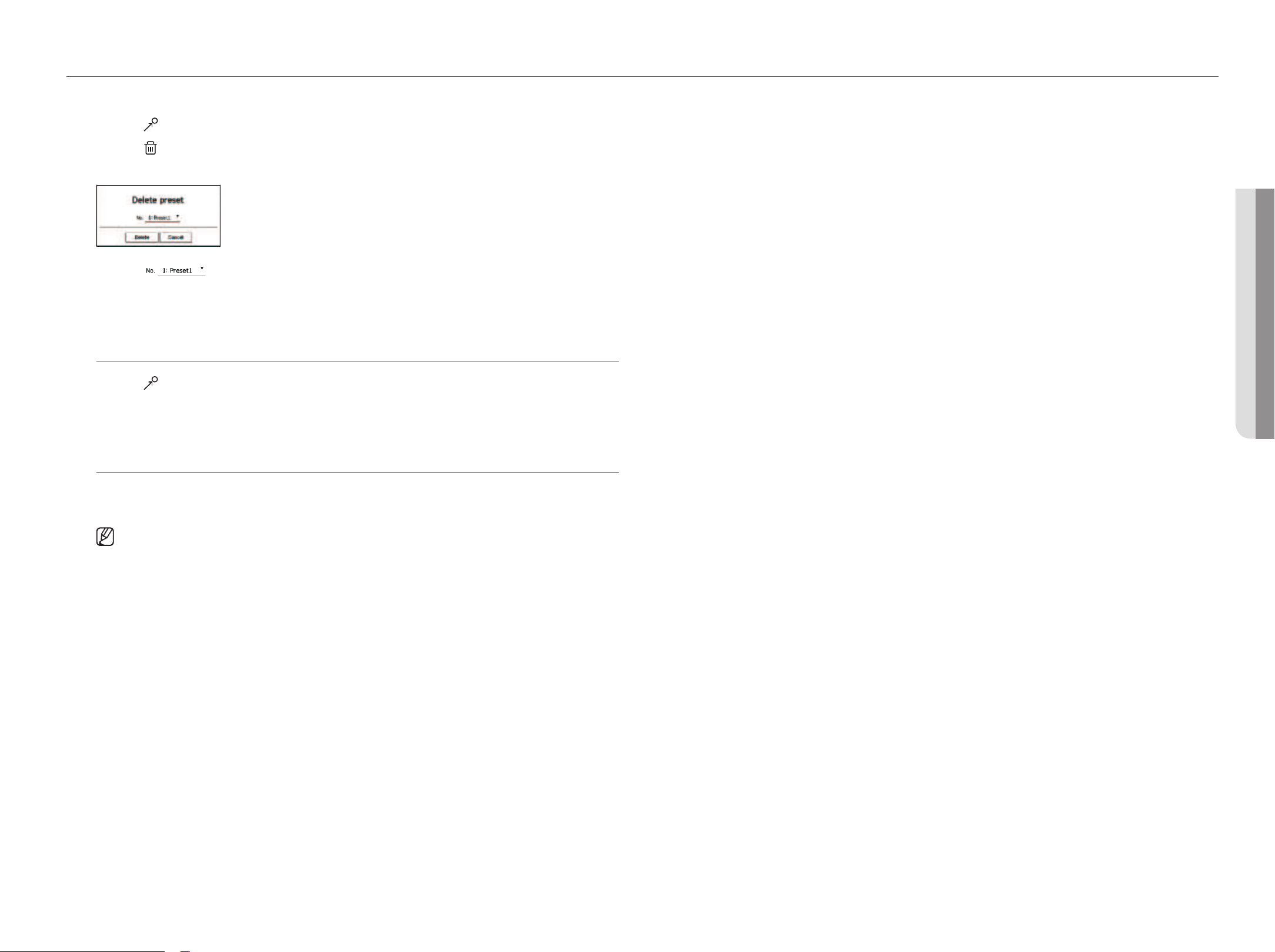
To delete a registered preset
1. Click <
>.
2. Click <
>.
The "Delete preset" window will appear.
3. Click <
> to select the preset to delete.
4. Click <Delete>.
The selected preset will be deleted.
Running preset
1. Click <
>.
2. Click the preset you want to run from the list.
The camera lens moves to the set position.
Run Swing (auto pan), group (scan), Tour, and Trace (pattern)
The running method of each function is the same as the preset operation method. For details on how to use it,
refer to the camera's user manual.
■
Depending on the camera's capabilities, only some features may be available.
32_ setup
setup
The camera, device, network and system can be set up.
■
You can check the following setup screen configuration when it is in <Standalone> operation mode.
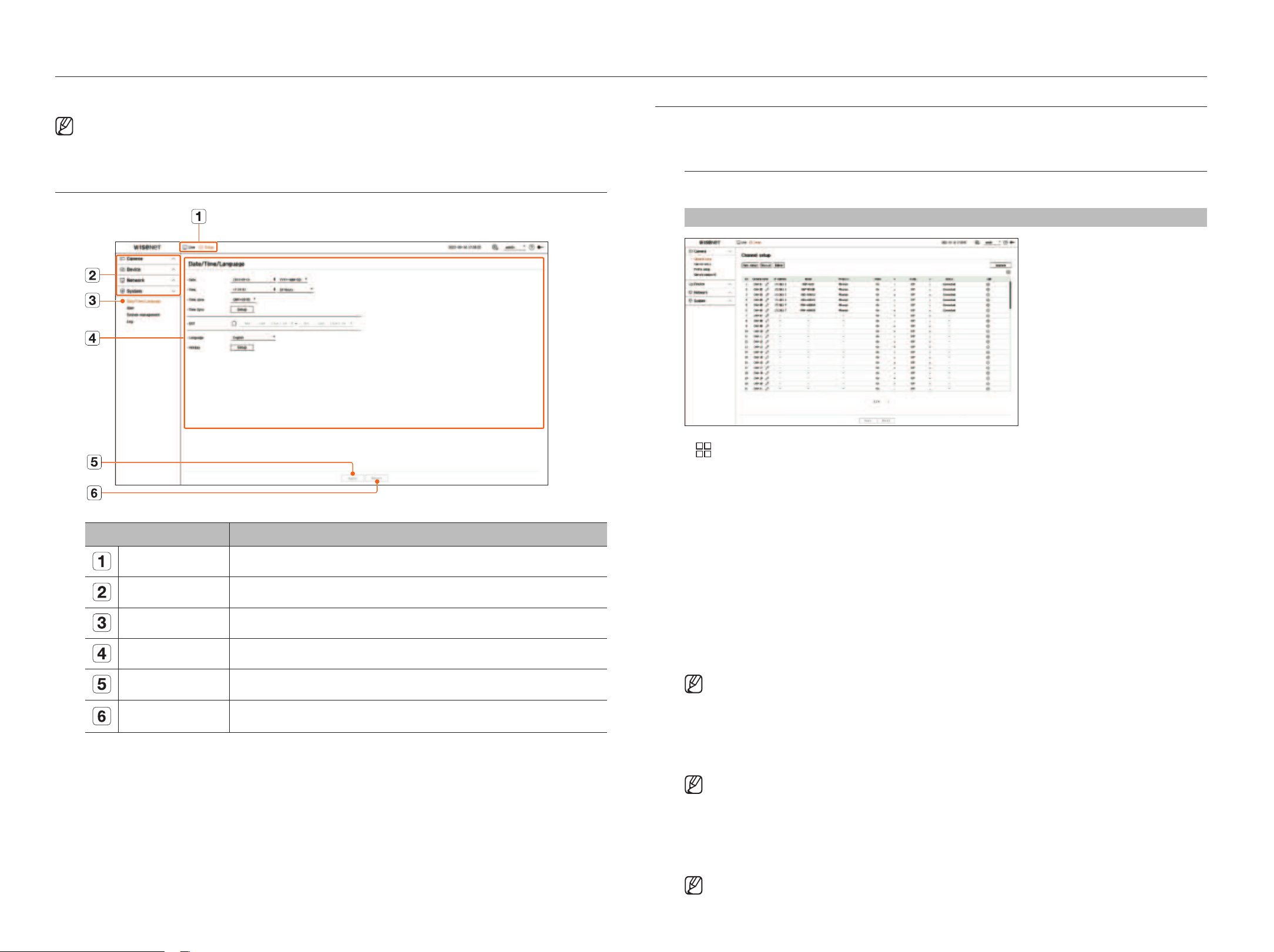
SCREEN lAyOUT Of ThE SETUp
Name Functions
Menu
Click each menu to go to the menu screen.
Top menu list
Configure the settings or select a parent item to change the existing settings.
Sub-menu list
Among the sub-menus of selected parent menu, select a desired item to set.
Detailed Menu Click desired item's input field to change and enter a desired value.
Apply
Apply the modified settings.
Revert
Revert to the settings used before the change.
SETTINg ThE CAmERA
You can access the channel setup, camera setup, profiles, and camera password-related settings.
Channel setup
You can register a network camera for each channel and make connections between them.
Setup > Camera > Channel setup
●
: Displays the camera of the channel as a list or thumbnail.
■
Cameras connected by ONVIF do not support preview.
●
Camera name: Provide a camera Name. You can enter up to 15 letters including spaces.
●
IP address: Display the IP address of a network camera.
●
Model: Show the camera model name.
●
Protocol: Show the protocol information of a registered network camera.
●
Video
– On/Off: You can turn on/off the selected channel's camera. If the camera video is turned off, a blank screen is
displayed.
– Covert 1: Displays information except for the video information from the selected channel.
The video is not displayed to protect privacy of a person under surveillance.
– Covert 2: Does not display all information of the selected channel, and only displays an empty screen.
■
Channels for which video is set as <Covert 1> or <Covert 2> do not produce sound.
●
Audio
– If set to
<On>
, you can turn the audio of the channel ON/OFF on the Live screen.
– When set to
<Off>
, the sound is turned off on the live screen.
■
Channels for which video is set to <Covert 1> or <Covert 2> do not produce sound on live screen even if the audio is set to <On>.
●
Status: Display the connection status.
●
Edit: You can change the connection information of the camera.
●
Upgrade: You can check the camera’s version, upgrade version, and status and upgrade it.
■
If you cannot register a camera after initializing the system, check the network setting. As the system is initialized and the network setting is
reset, the camera's network bandwidth will be different from the product's network bandwidth, so it will be impossible to register a camera.
English _33
• SETUp
setup
• SETUp
Automatic Registration of Network Cameras
1. In the
<Channel setup> field, click on the
<
Auto detect>
button.
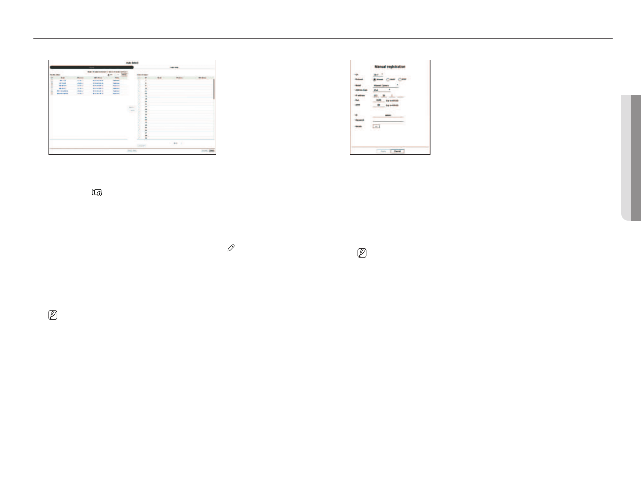
2. The <Auto detect> window will appear.
■
When you click < > on the camera list on the live screen, you can automatically search and register a camera.
3. Select a camera to register from the <Searched camera> list and click <Register>.
You can check the selected camera in the <Camera to register> list.
■
An already registered camera will be marked in blue in the list.
■
In case you search again or keep the same IP because the IP of the camera has not been assigned by the DHCP server yet
(Example: 192.168.1.100), click <Refresh> to confirm whether it is assigned.
■
<Status> displays the camera authorization status. If the status is <Auth failed>, then click <
> to enter the camera ID and password.
■
Click a header at the top of the list to sort the list according to that header.
4. To change the IP address of the camera, select the desired camera from the <Camera to register> list and
press the <Change Ip> button.
5. Click <Next> at the bottom of the screen to set the registered camera channel.
6. Press the <Register> button on the lower right of the screen to register the selected camera.
■
If you register a camera using a user account—not an admin account—the camera features may be limited.
■
When changing the camera ID and password in the camera webviewer, if the camera is already registered on a decoder, you must change the ID
and password of the camera registered on the decoder as well.
■
When the camera is in the factory default status, it will be changed to the ID and password set in "Setup > Camera > Camera password".
■
If the ID and password of a camera are already set, the ID and password set in "Setup > Camera > Camera password" will be registered.
(up to 3 sets)
■
Wisenet camera is registered via Wisenet protocol while a third party camera is registered via ONVIF protocol.
■
You must not connect a device running a DHCP server to the PoE port or camera setup port. (Example: Router)
■
If a camera uses its own power source, the user must manually or automatically register a camera.
manual Registration of Network Cameras
1. Click <manual> in the <Channel setup> field.
2. The <manual registration> window will appear.
■
Click < + > on the camera list on the live screen to manually register a camera.
3. Select a channel and protocol used to connect to a camera.
The input items may differ depending on the selected protocol.
●
Wisenet: Wisenet camera's protocol can be used.
●
ONVIF: Means the camera supports ONVIF protocols. When connecting a camera whose name cannot be
found from the list, select <ONVIf>.
■
When registering a camera with ONVIF, if the system time of the camera and the decoder is more than 2 minutes, the camera cannot be
registered. Synchronize the time setting of the camera and decoder before registration.
●
RTSP: Comply with RFC 2326, one of the "Real Time Streaming Protocols
(
RTSP
)
" for real-time streaming.
4. If you select the
<
Wisenet
>
protocol, check options as necessary.
●
Model: Select a camera model.
– Unknown: Select when the camera model cannot be identified.
– Wisenet Camera: You can register Hanwha Techwin's cameras and encoders.
– Wisenet Multi-Channel: You can register Hanwha Techwin's multi-directional cameras and multi-imager
cameras. A multi-channel camera is a camera that has multiple camera modules in one body. If a camera
is automatically registered to a decoder, you can register several channels at once. However, if you want
to manually register it, you need to register one channel at a time.

34_ setup
●
Address type: Select the access address type of a camera.
■
The supported address type may differ depending on the type of the connected product.
– IPv4/IPv6: Use in case you have to directly enter the IP address of the camera.
– Wisenet DDNS: Can be used when the camera is registered on the Wisenet DDNS (ddns.hanwha-security.
com) server. Enter the registered domain in DDNS ID.
Example)
In case it is http://ddns.hanwha-security.com/snb5000, then enter snb5000 in Wisenet DDNS
– URL: Use when you enter a URL.
■
The DDNS specs supported by each camera can be checked in the user manual of the corresponding camera.
●
IP address: Provide the IP address of the camera.
●
Port: Enter the device port of the camera.
■
Depending on a camera product, device ports might not be supported.
●
HTTP: Enter the HTTP port of the camera.
●
ID: Provide the ID of the camera that you want to register.
●
Password: Enter the password of the camera to be registered.
●
Details: The streaming mode can be set up.
5. Select
<ONVIf
> or
<RTSp
>
for the protocol and enter your input for each field that appears.
●
ONVIF: After selecting an IP type, set IP address, ONVIF port, ID, password, and details.
– IP type: Select the IP type of the camera.
– IP address: Enter the camera's IP address.
– ONVIF port: Enter the port number when the address type is IPv4 or IPv6.
– Channel: Enter the channel to register the camera.
– ID: Enter camera ID.
– Password: Enter the camera password.
– Details: The TLS usage status, authentication mode, and streaming mode can be set up.
●
RTSP: Set URL, ID, password, and details.
– URL: Enter your RTSP access address. For more information, see your camera user manual.
– ID: Enter camera ID.
– Password: Enter the camera password.
– Details: The streaming mode can be set up.
■
When choosing the ONVIF, RTSP protocol, you can set the streaming mode in the details.
– TCP: The connection with the network camera operates through RTP over TCP.
– UDP: The connection with the network camera operates through RTP over UDP.
– HTTP: The connection with the network camera operates in the RTP over TCP (HTTP) mode.
– HTTPS: The connection with the network camera operates in the RTP over TCP (HTTPS) mode.
To check the error details of camera registration
If you failed to register a camera, the reason for the failure will be displayed.
●
Connection failed due to an unknown reason : This message appears if the camera has failed to be
registered due to unknown connection status.
●
Disconnected because camera account has been locked. : When you enter the wrong ID/password 5 times
to log in to the camera account, this message is displayed.
Try to log in again after 30 seconds. If the same message appears, you may need to check whether someone
has tried to access your camera account from the outside.
●
Connected successfully. : This message appears if the camera is connected successfully.
●
model information is wrong. please provide the correct model name. : This message appears if the model
information provided for registering the camera is incorrect.
●
Authentication is failed. : This message appears if the ID or password provided for registering the camera is
incorrect.
●
Access failed as the max number of simultaneous users is exceeded. : This message appears if the
concurrent user count exceeds the upper limit.
●
Connection has failed due to a wrong hTTp port : This message appears if the HTTP port number of the
camera is invalid.
●
Connection has failed. Unknown connection error. : This message appears if the camera has failed to be
connected due to an unknown error.
●
User model modification: When registering a new camera, it is named according to the device's default if the
user sets the model to <Wisenet Camera>. In case automatic registration fails, the user can change the model
name of the camera to be registered.
To edit camera profile
For more information on profile changes, see the "Setup > Setting the Camera > profile setup” page in the
table of contents.
■
For the decoder, if the live profile and remote profile are set differently, one camera can produce 2 types of streams. Especially, note that the live
profile may vary depending on the screen split mode.
■
For cameras, if applied with one profile only, the produced frame rate is fixed as the profile specifies; if applied with multiple profiles, produced
video stream's frame rate is not guaranteed. For example, if applied with 2 profiles of 30fps, the camera may transmit streams at 20fps.
Delete Network Camera
1. Click <Delete> in the <Channel setup> field.
2. When the delete window appears, select the camera channel to delete.
■
Click <All channels> to select the cameras of all channels.
3. Click <Ok> to delete the camera of the selected channel.
English _35
• SETUp
setup
• SETUp
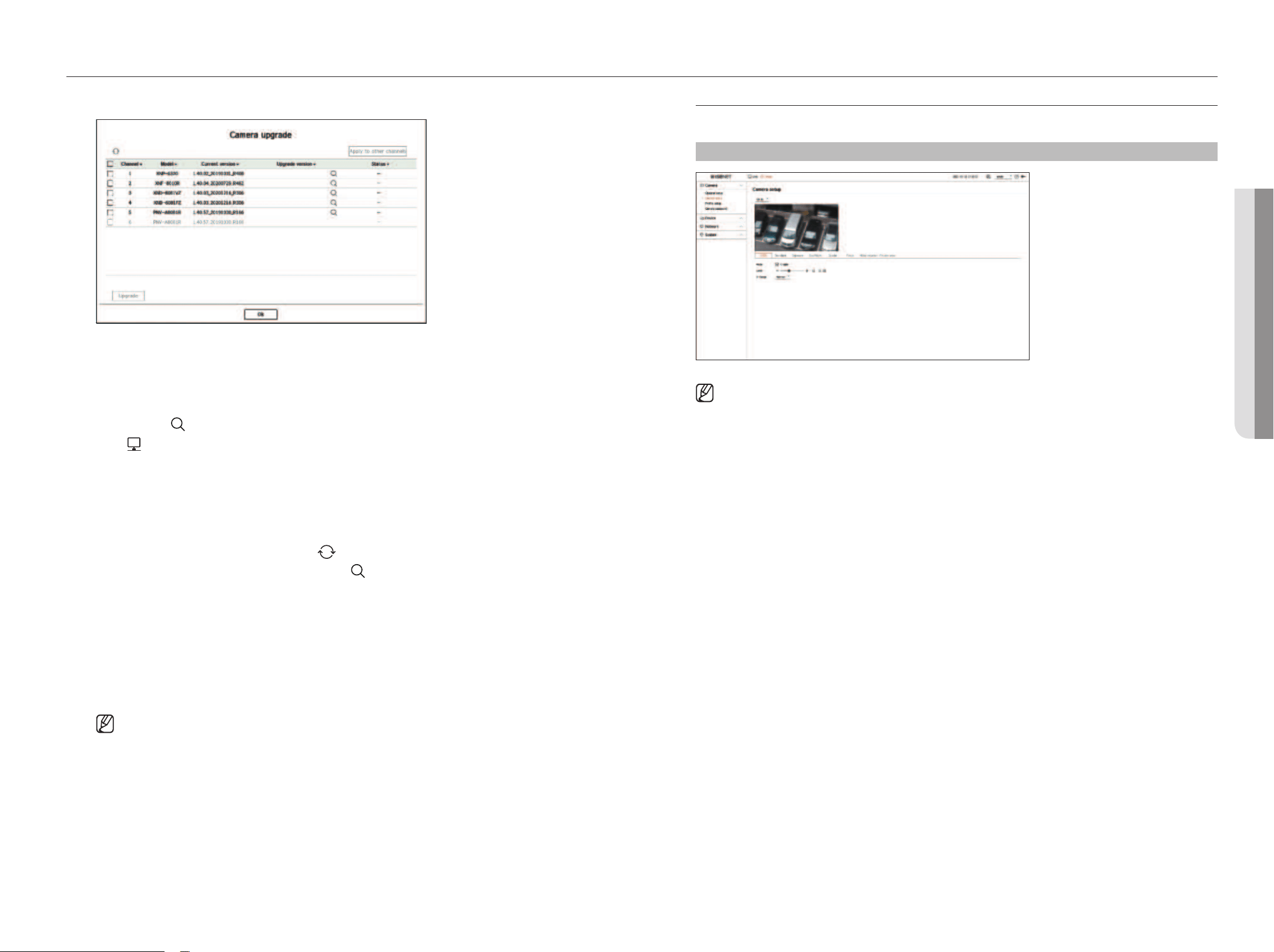
Network Camera firmware Upgrade
●
Channel: Displays channel information.
●
Model: Displays the camera model information.
●
Current version: Displays the current camera firmware version.
●
Upgrade version: Displays the firmware version to upgrade.
– Press the <
> button to select the firmware manually within the USB.
– <
> indicates an upgrade via a remote server.
●
Status: Displays the status of the ongoing upgrade (upgrading, successful, failed).
1. Click <Upgrade> in the <Channel setup> field.
2. Displays the upgradeable channel list among the connected cameras.
■
If newer firmware exists on the remote server, the upgrade version is displayed, and the check box is automatically selected.
■
If you do not see the upgrade version, you can press the < > button to get the upgrade version information from the server.
■
Connect the USB with the camera firmware to a decoder and click < > to search and select firmware files from the USB.
■
Select a channel and press the <Apply to other channels> button to apply the firmware to other channels connected to the same model at once.
3. Check the box of the channel you want to upgrade.
4. Click the <Upgrade> button. The camera firmware upgrade starts.
■
You can move to another menu while upgrading.
■
Click <Stop> during an upgrade to stop upgrading.
■
When the upgrade is completed, you can see the result in the popup window.
■
Firmware upgrade is available only for channels connected with the Wisenet protocol and the camera’s administrator account.
■
If the upgrade version is not displayed even though the camera’s firmware is out of date, check the network settings.
■
If there are more than 50 firmware files in the top USB folder, the file may not be scanned.
■
Disconnecting the USB from the decoder during an upgrade over the USB may cause the system to reboot.
Camera setup
You can set the camera while viewing the live video of the selected camera.
Setup > Camera > Camera setup
■
You can use this feature in the following cases:
1. A camera connected to Wisenet protocols.
2. A camera connected with admin permissions.
■
For more details on camera setup, refer to the camera user manual.
Settings and operational spec vary depending on each camera.
■
This function is not supported in some models.
SSDR
If there is a significant difference between the dark and the bright areas, increase the brightness of the dark areas
to maintain the level of brightness of the entire area.
The mode, level, and D-Range can be set up.
backlight
You can view both bright and dark areas.
The mode, WDR level, WDR black level, and WDR white level can be set up.
Exposure
You can adjust the exposure of your camera.
The brightness, shutter, SSNR, Sens-up, Iris/Lens, and AGC can be set up.
●
Brightness: Adjusts the brightness by setting the exposure value.
●
Shutter: Adjusts the brightness by controlling the camera shutter speed. If you select shutter, you can set
among the items below.
– Auto: Adjusts the brightness automatically, controlling the shutter speed of the camera.
– ESC (Electronic Shutter Control): Adjusts the brightness automatically, controlling the shutter speed
according to the surrounding brightness.
– Manual: Adjust the brightness by manually selecting the maximum/minimum shutter speed of the camera.
– Anti-flicker: Reduces the shaking of the video when the screen shakes occur due to different frequencies and
illumination. The shutter speed cannot be set when the anti-flicker frequency is selected.
36_ setup
●
SSNR: Reduce noise, even in dark places, and minimize the afterimage of the object to control brightness.
●
Sens-up: Automatically adjusts the shutter speed according to the brightness of the current light.
●
IRIS/Lens: Adjusts the brightness by automatically or manually adjusting the camera IRIS and lens.
●
AGC: Adjust the brightness by amplifying the camera's electrical signal when images are shot in the dark.
Day/Night
You can change the mode to adjust the color and contrast.
The mode, dwell time, negative color, duration, alarm input, switching brightness, simple focus after day/night,
and activation time (color) can be set up.
●
You can select the day/night video display mode in <mode>.
– Color: Images are always displayed in color.
– B/W: Images are always displayed in B/W
– Auto: The video will be displayed in color in normal environments and in B/W at night.
– External: Displays a color or B/W video by linking an external infrared camera to the alarm input terminal.
Set the alarm input item when selecting the <External>.
– Schedule: Directly enter the activation time (color) to control video display mode. Click <Setup> and enter
the activation time.
Special
The DIS (Digital Image Stabilization), defog function, and level can be set up.
focus
You can adjust the focus of you camera's video.
Focus, zoom, simple focus, focus initialization can be set up.
Video rotation
Mirror mode, flip, and hallway view can be set up.
privacy area
You can set an area to be hidden in the camera image range to protect privacy. You can select whether or not to
use the privacy setting and set up 32 new privacy areas.
■
For a PTZ camera, it is not possible to configure settings, and even when it is configured, the set area may be incorrect.
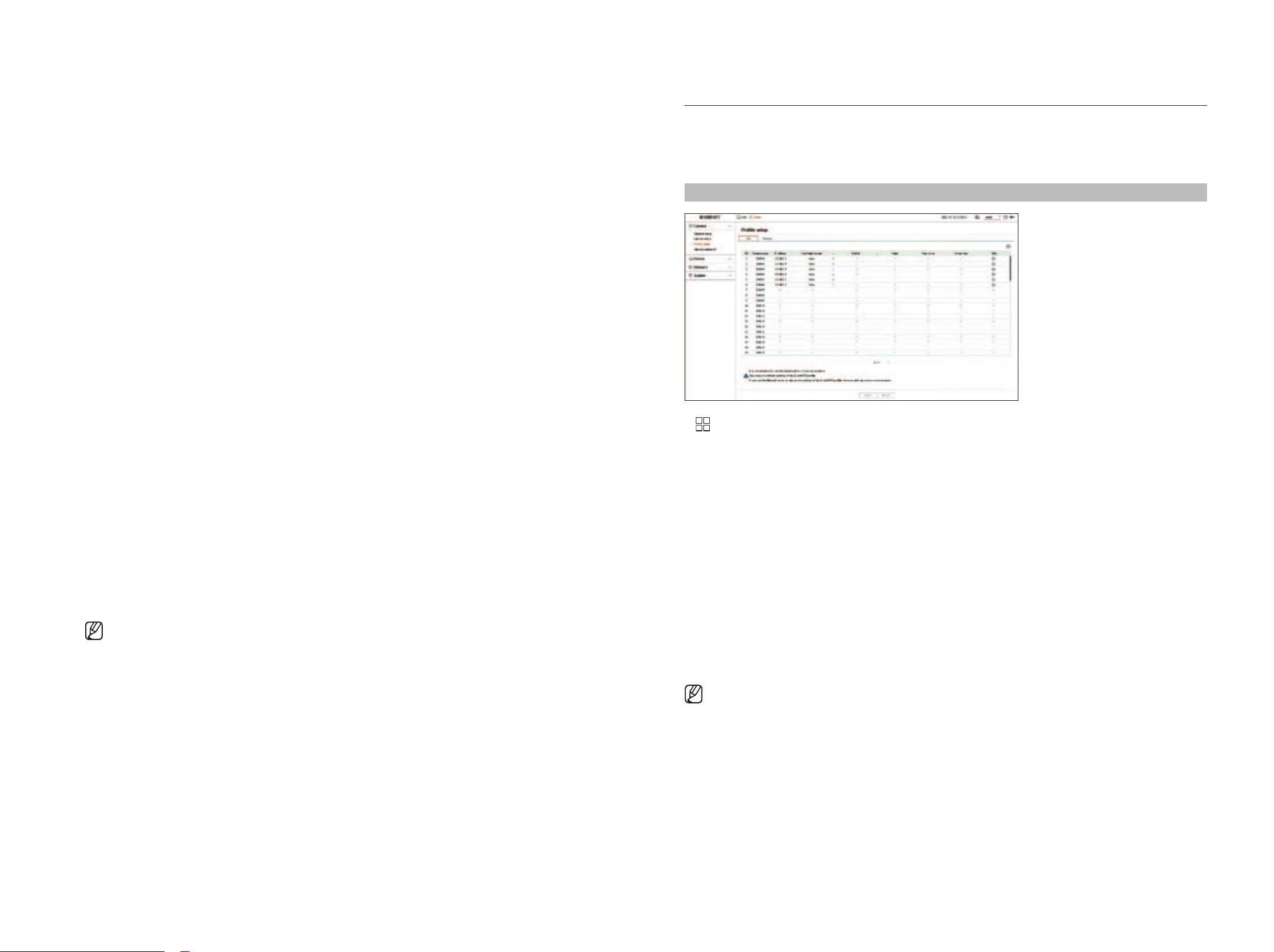
profile setup
Setting the live profile
You can change the live settings of the network camera.
Setup > Camera > profile setup > live
●
: Displays the camera of the channel as a list or thumbnail.
●
Camera name: Display the camera name.
●
IP address: Display the IP address of a camera.
●
Live Replacement: You can select the live profile setup mode.
If you select <manual> the profile setup items are enabled, and you can change settings manually.
– Auto: For the profile for live monitoring, a profile optimized for each split mode is displayed, along with the
‘live4NVR' profile automatically generated at the time of the camera registration.
– Manual: Live monitoring is performed with the profile selected by the user from the registered camera
profiles.
●
Profile: You can set the camera profile.
●
Codec: Show the codec of the selected profile.
●
Resolution: Show the resolution of the selected profile.
●
Frame rate: Show the frame rate of the selected profile.
●
Edit: You can add, change, and delete the camera profiles.
■
If you use video settings, such as bandwidth, resolution, or frame rate, higher than recommended requirements, frame drops may occur.
If frame drops occur, setting the profile requirements as below is recommended:
– Recommended profile requirements: 640x360, 30 fps, 512 Kbps
English _37
• SETUp
setup
• SETUp
Setting the Remote profile
You can set the video profile transmitted to the network.
Setup > Camera > profile setup > Remote
●
: Displays the camera of the channel as a list or thumbnail.
●
Camera name: Display the camera name.
●
IP address: Display the IP address of a camera.
●
Profile: You can set the remote profile of the connected camera.
●
Codec: You can see the codec of the selected remote profile.
●
Resolution: You can see the resolution of the selected remote profile.
●
Frame rate: You can see the frame rate of the selected remote profile.
●
Edit: You can add, change, and delete the camera profiles.
■
The set remote profile can be used as the video profile of the extended monitor depending on the <Live Replacement> setting of the live
profile.
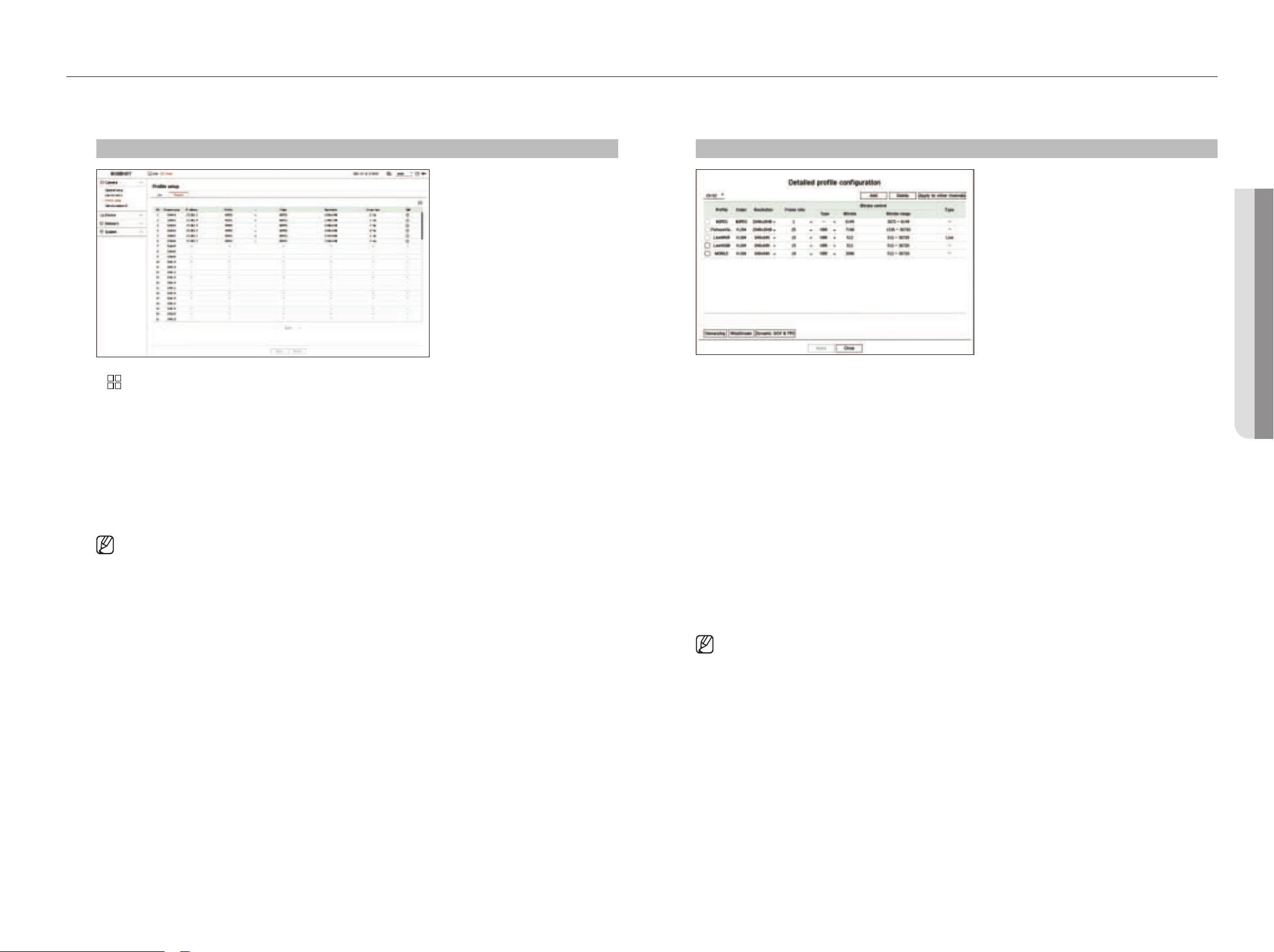
Editing the profiles
You can change the video settings of a registered network camera for each channel.
Setup > Camera > profile setup
●
Channel selection: You can select camera channels to change their video transmission settings.
●
Add: You can add camera profile. If you click <Add> , an Add window will appear.
Enter the information and click on the <Ok> button to add it to the list.
●
Delete: You can delete the selected profile from the list.
●
Apply to other channels: If you select <Apply to other channels>, the “Apply to other channels”
confirmation window will appear.
After selecting channels that the settings will be applied to, click on <Ok> to apply them to the selected
channels.
●
Profile: You can check the video profile of the camera connected to the camera setup.
●
Codec: You can check the codec for the selected channel.
●
Resolution: You can change the resolution of the selected channel.
●
Frame rate: You can change the frame rate of the selected channel.
●
Bitrate control: You can change the type of bitrate of the selected channel.
●
Type: You can see the profile that is currently applied.
■
If you change specific profile settings for each product, the frame rate's setup range may be changed.
Example) If you set the frame rate for the first profile to 30 fps, then the setting range for the second profile may be changed to 15 fps.
■
Any settings other than codec, resolution, and frame rates can be changed in the setup menu of the camera webviewer. For a camera
webviewer, see the "Setup Viewer > Setting the Camera > Camera setup" in the table of contents. Click <Camera webviewer> to
connect.
■
If you change the settings of the profile you are currently using, the screen may break for a certain period of time.
■
Changes made to your camera setup page will be applied immediately. But any changes made through the camera's online website may take
up to 3 minutes to apply the changes.
■
Bitrate settings are not supported for ONVIF cameras.
38_ setup
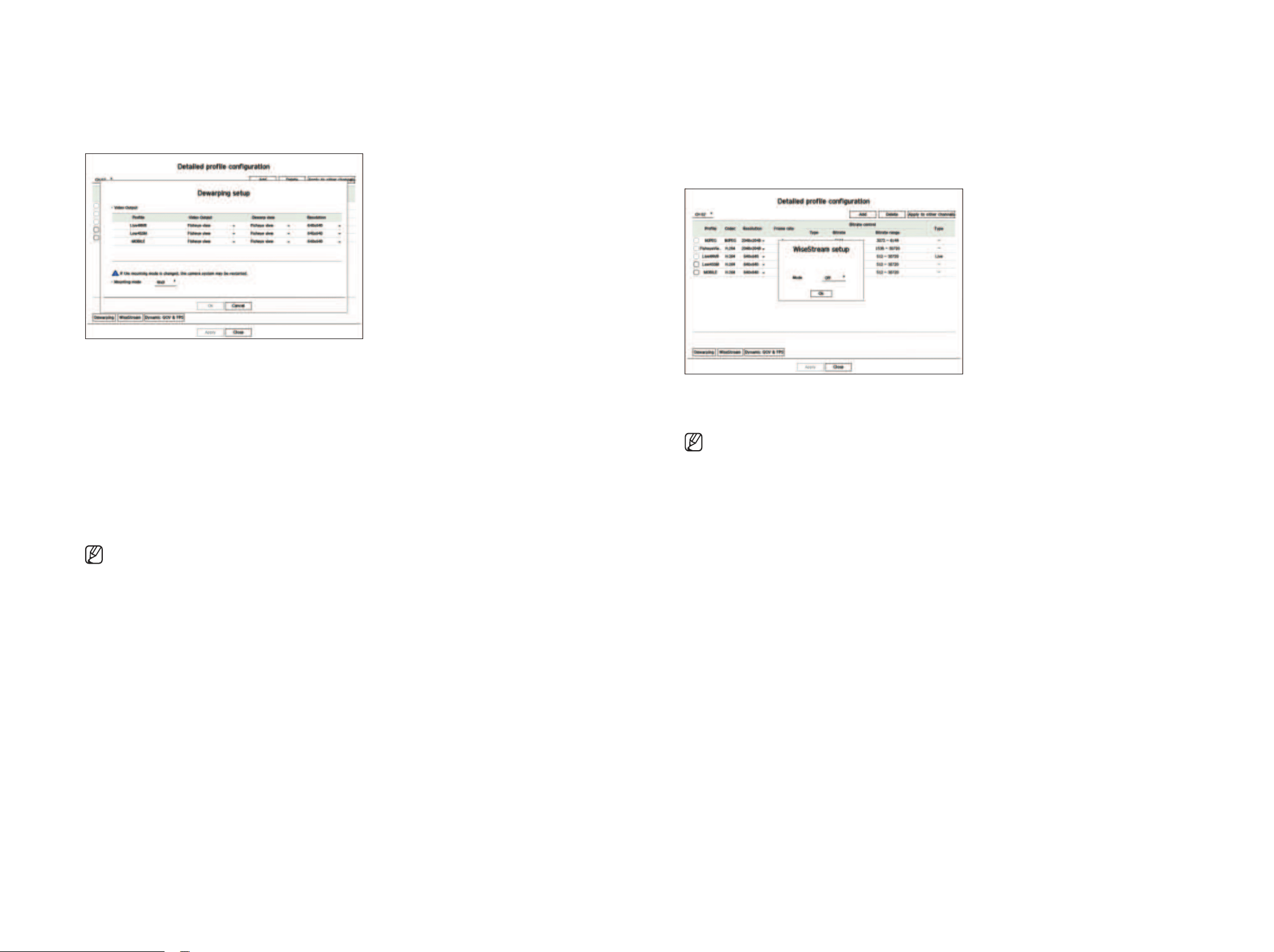
Dewarping Setup
Press the <Dewarping> button at the bottom of the <Detailed profile configuration> window to go to the
distortion correction setup popup window for each channel.
●
Profile: Displays the profile type.
●
Video Output / Dewarp view: You can set the <Video Output> and <Dewarp view> for each profile type.
– Fisheye view: If you select <fisheye view> for <Video Output>, <Dewarp view> is automatically selected
as <fisheye view>.
– Dewarp view: If you select <Dewarp view> from <Video Output>, then you can choose from <Quad
view>, <panorama>, or <Quad view 1 - 4> for <Dewarp view>.
■
You can select view modes supported by your camera.
●
Resolution: You can set the resolution of the profile.
●
Mounting mode: You can change fisheye installation type. You can select a view mode from among ceiling/
ground/wall depending on the installation location.
■
If there is no camera registered to a decoder that supports the fisheye view, you cannot set dewarping.
how to set WiseStream
Function to analyze the complexity of the video and effectively reduce the data size while maintaining the
quality. For details, refer to the camera's help or the product's user guide.
Press the <WiseStream> button at the bottom of the <Detailed profile configuration> screen to go to the
WiseStream setup popup window for the channel.
●
Mode: You can choose the degree of video compression. You can choose from <Off>, <low>, <medium>, and
<high>.
■
If there is no camera registered to a decoder that supports WiseStream, you cannot set WiseStream.
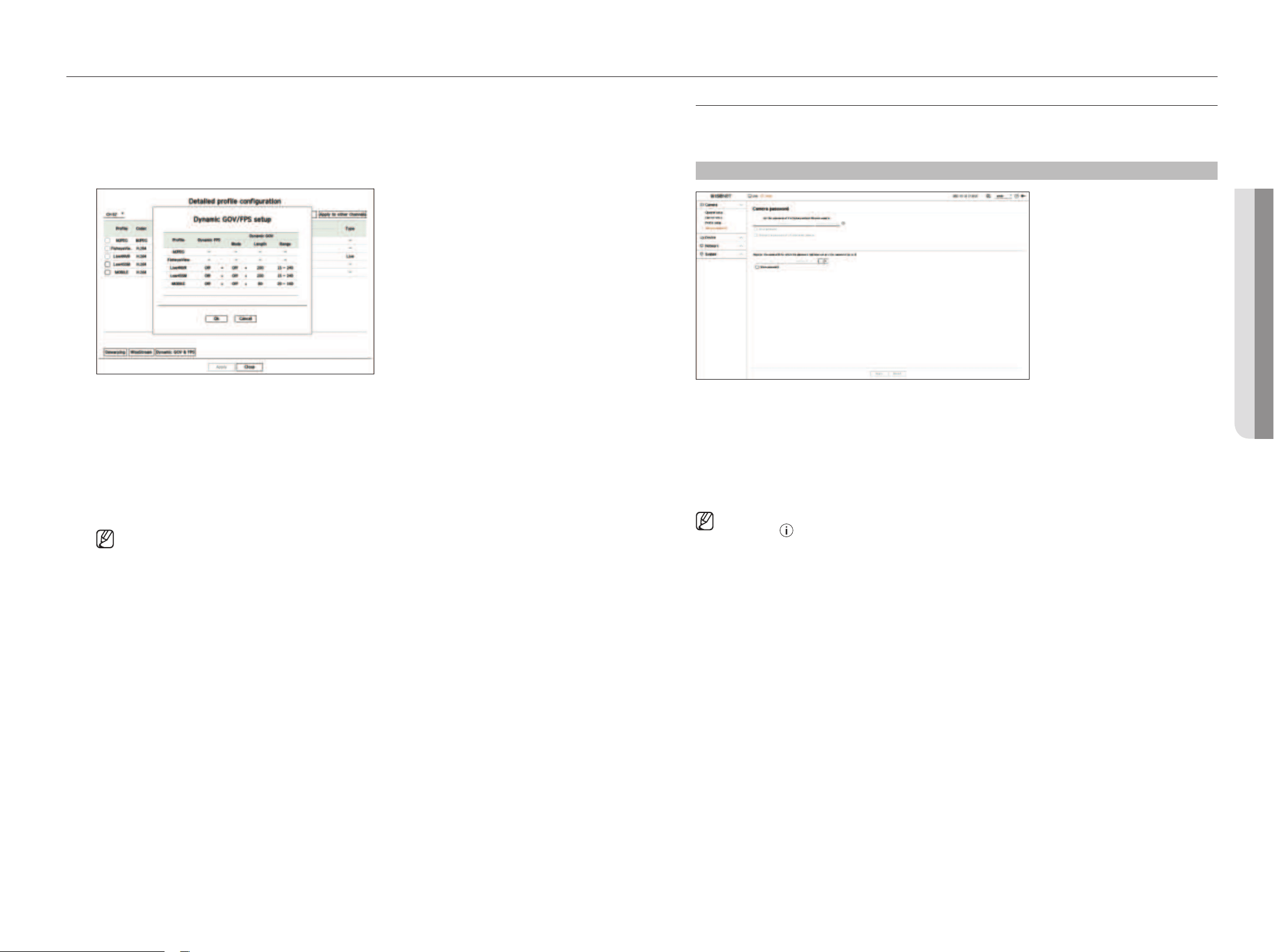
English _39
• SETUp
setup
• SETUp
Camera password setup
You can change the passwords of all registered cameras at once.
You can register the ID and password of the camera that you use.
Setup > Camera > Camera password
●
Password: Enter a new password for the camera in the factory default status according to the password setup
rules.
The initial password for the camera must be entered.
●
Confirm password: Input the new password again.
●
ID: Enter the ID and the ID of a camera whose password is set.
●
Password: Enter the password of a camera whose ID and password are set.
■
When the password is in factory default status, it can be changed and managed in a batch.
■
If you click < >, a basic guide for password setup is displayed.
■
Check <Show password> to see the password that you are currently entering.
■
If you check the <Change the password of all registered cameras> option, the passwords of all cameras are changed with the entered
password.
■
Up to 3 sets of camera IDs with passwords and passwords can be registered.
You can auto-detect a camera with the ID/PW information of a registered camera on the "Channel setup > Auto detect" screen and directly
register.
■
A camera password registered with ONVIF and RTSP cannot be changed.
Dynamic gOV/fpS setup
Dynamic GOV is a function that automatically changes the length of GOV depending on the video situation. For
details, refer to the camera's help or the product's user guide.
At the bottom of the <Detailed profile configuration> screen, press the <Dynamic gOV & fpS> button to
open the dynamic GOV/FPS setup popup for the channel.
●
Profile: Shows the video profile of the connected camera setup.
●
Dynamic FPS: Automatically adjusts the frame rate (frames per second) based on the video conditions.
●
Dynamic GOV
– Mode: Set the GOV length to change automatically.
– Length: Enter the maximum GOV length value to be applied when there is no motion in the video. Minimum
GOV value can be set on the camera web page.
– Range: The range of the input value of <length> is displayed.
■
Any profile not supported with the dynamic GOV/FPS setting is marked with '-'.
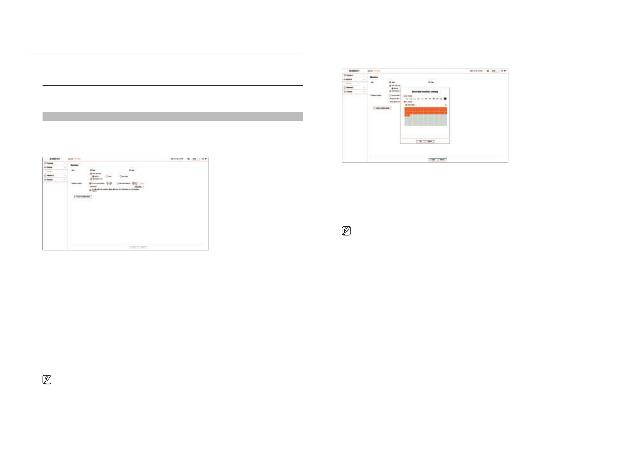
40_ setup
SETTINg ThE DEVICE
Can make detailed settings related to the monitor.
monitor
You can set the information displayed on the monitor the information location as well as the video output
method.
Setup > Device > monitor
monitor settings
You can set the settings related to the monitor output, such as screen displays and video output.
●
OSD: Displays only the checked items from among the date, time, channel name, and information icon on the
screen.
– You can adjust the size of the channel name displayed on the live screen. Choose from <Default>, <large>,
<Very large>.
●
Multiple displays: You can set the resolution for the video display.
You can set the resolution of a device that supports a secondary monitor by selecting <Duplicate these
displays> or <Extend these displays> mode.
– Duplicate these displays: You can set the video display resolution of the primary monitor and secondary
monitor to be the same. When operating in duplicate mode, if you set a resolution that exceeds 1920 x 1080,
then the video will not be displayed on the secondary monitor.
– Extend these displays: You can set the video display resolution of the primary monitor and the extended
monitor separately.
■
The primary monitor supports 4K resolution (or 1080p), and the secondary monitor supports 1080p resolution.
■
If the newly selected resolution does not fit with the monitor, the display won’t function properly. In this case, wait until the native resolution is
restored and then switch to another resolution of your choice.
■
The output terminals of the main monitor and the extended monitor may be different depending on the decoder model.
– Primary monitor: HDMI
– Secondary monitor: HDMI or VGA
Expansion monitor settings
This function is only available for products that support the use of an extended monitor.
1. Select <Extend these displays> on the video display and click <Setup>.
You can change the layout of the extended monitor.
2. Select a desired split mode.
3. You can select as many channels from the channel table as the channels of the selected split mode to see the
screen on a monitor.
■
When the extended mode is selected, the maximum resolution of the video output on the primary monitor (HDMI) is limited to 1920 x 1080.
■
If the newly selected resolution does not fit with the monitor, the display won’t function properly. In this case, wait until the native resolution is
restored and then switch to another resolution of your choice.
■
When setting the sequence switching time, consider the network environment.
■
The profile used in the live output of the expanded monitor uses a remote profile. If the user changes the remote profile, the video output of the
expanded monitor may be affected.
■
By setting the monitor to duplicate mode, you can specify the monitor up to the maximum split mode supported by the decoder. If you set the
monitor to extended mode, the screen of a secondary monitor can be designated up to 25 splits depending on the decoder model.
■
The dynamic layout function can only be set on the primary monitor.
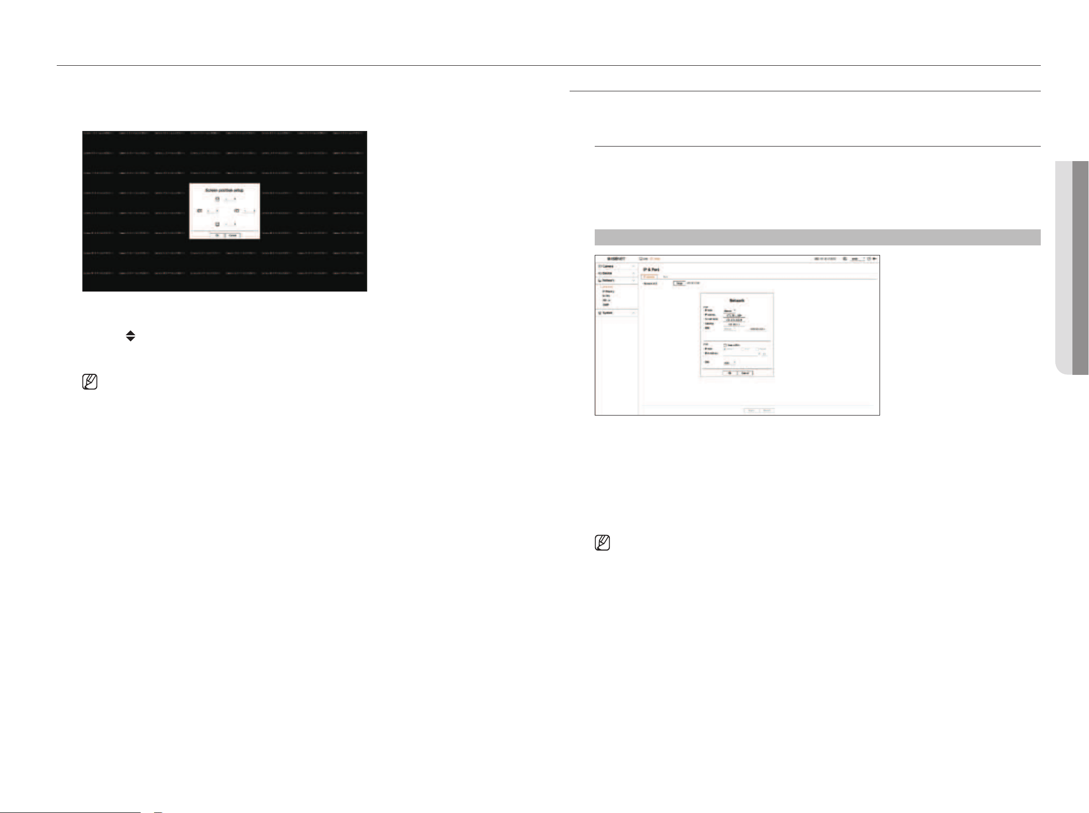
English _41
• SETUp
setup
• SETUp
Display position settings
On some monitors, depending on their status, the information of a decoder (camera name, icon) may not be
displayed. Then, you can change the display position of the data.
1. Click
<Screen position setup>
on the monitor setup screen.
2. Using
<
>
button to adjust the screen that is cut off.
3. Click
<
Ok
>
.
■
This product only supports 30Hz in 4k resolution.
SETTINg ThE NETWORK
The network settings of decoders can be set up.
Ip & port
You can set the network connection route and protocol.
Setting a network connection
Sets the protocol and environment of the network.
Setup > Network > Ip & port > Ip Address
●
Network (All): Can be used as a common port for the camera and web viewer connection.
●
Setup
– IP type: Select the type of network access.
– IP address, Subnet mask, Gateway, DNS
■
Manual: The IP address, subnet mask, gateway, and DNS can be entered manually.
■
DHCP: The IP address, subnet mask, gateway, and DNS can be automatically set.
■
You can only directly enter the DNS value of the DHCP when <Manual> is selected.
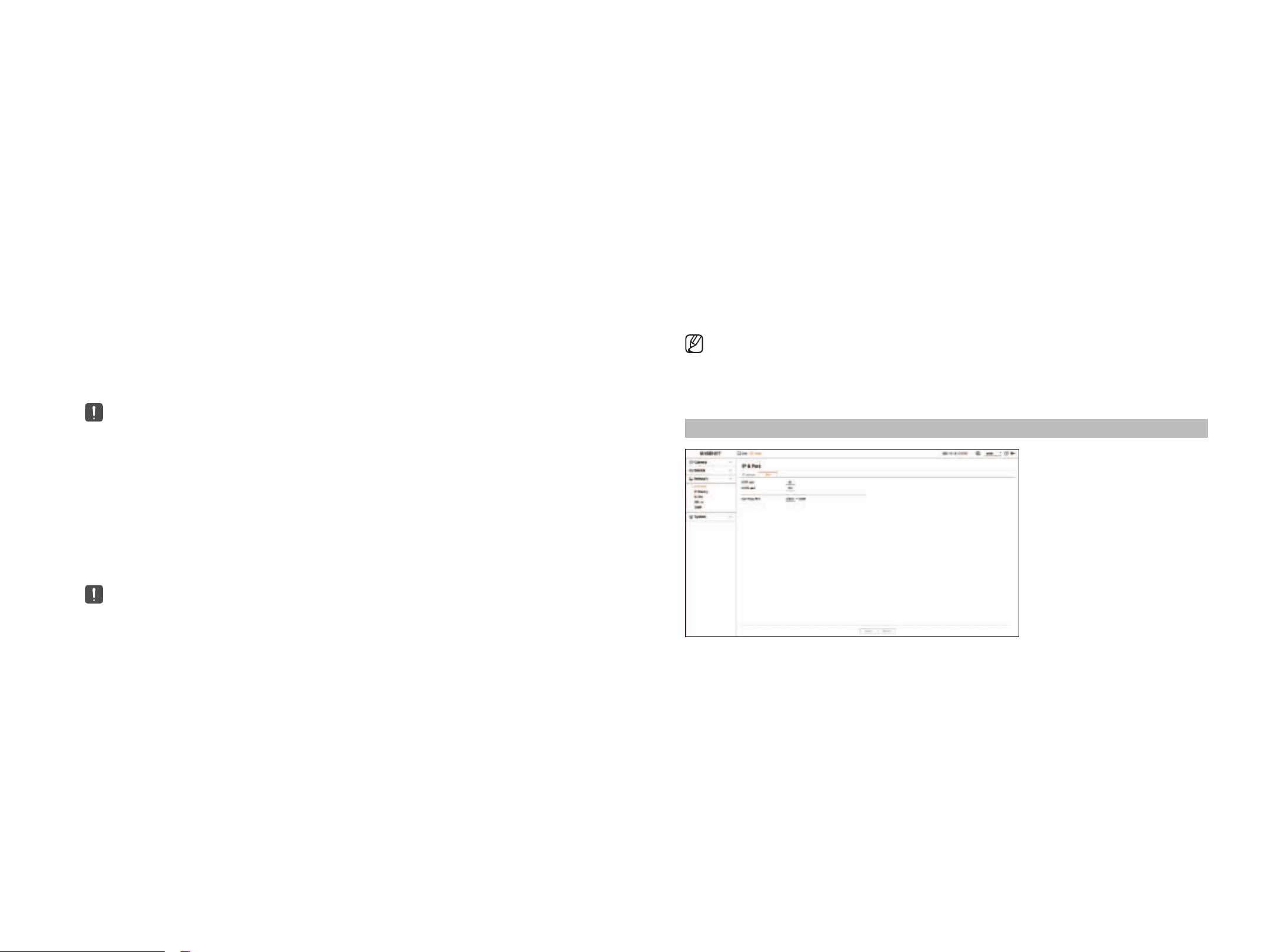
42_ setup
Connecting and Setting the Network
Networking may differ from the connection method, check your environment before setting the connection
mode.
When no router is used
●
manual Setup mode
– Internet connection method: Connect with a static IP or dedicated line, or connect a decoder and a remote
user in the LAN (local area network) environment.
– Network setting method: Set the connected decoder's <Ip type> to <manual>.
■
Consult your network manager for IP, Gateway and Subnet Mask.
●
DhCp mode
– Internet connection method: Connect a decoder directly to a cable modem, connect a decoder directly to a
DHCP modem, or connect a decoder directly to the optical LAN.
– Network setting method: Set the connected decoder's <Ip type> to <DhCp>.
When a router is used
■
Check the following items to avoid collision with the decoder's static IP.
●
Setting up the Decoder Static Ip
– Internet connection method: Connect a decoder to an IP router connected to a cable modem, or connect a
decoder to an IP router in a LAN (local area network) environment.
●
Setting up the Decoder Network
1. Set the <Ip type> of the connected decoder to
<manual>
.
2. Make sure that the IP is within the static IP range provided by the IP router.
IP address, Gateway, and Subnet mask: Consult your network manager.
■
If a DHCP server is configured with starting address (192.168.0.100) and end address (192.168.0.200), you should set the IP address out of the
configured DHCP range (192.168.0.2 ~ 192.168.0.99 and 192.168.0.201 ~ 192.168.0.254).
3. Check the Gateway address and subnet mask are equal to those set in the Broadband Router.
●
Setting the DhCp Ip Address of the broadband Router
1. Enter the access address of the IP router in the internet browser of the local PC connected to the IP router to
access the setup menu of the IP router. (ex: http://192.168.1.1).
2. In this case, first, specify the Windows network settings of the local PC as in the following example.
Example) IP: 192.168.1.2
Subnet Mask: 255.255.255.0
Gateway: 192.168.1.1
– Once connected to the Broadband Router, it prompts with a password. If you do not enter anything for the
User Name, enter “admin” in the password and click <Ok>, then the IP router setting page will appear.
– Access the router's DHCP configuration menu and set its DHCP server activation, and provide the start and
end address.
■
Start address: 192.168.0.100
■
End address: 192.168.0.200
■
Above steps may differ from the router devices depending on the manufacturer.
port Setting
Setup > Network > Ip & port > port
●
HTTP port: Enter the port value for the HTTP web viewer. The initial value is set to <80>.
●
HTTPS port: Enter the port value for the HTTPS web viewer. The initial value is set to <443>.
■
HTTPS is a version of HTTP web communication protocol with advanced security. If security is important when accessing the web viewer, enable the
HTTPS port.
●
Cam Proxy Port: Sets the camera proxy port. The initial value is set to <10001>.
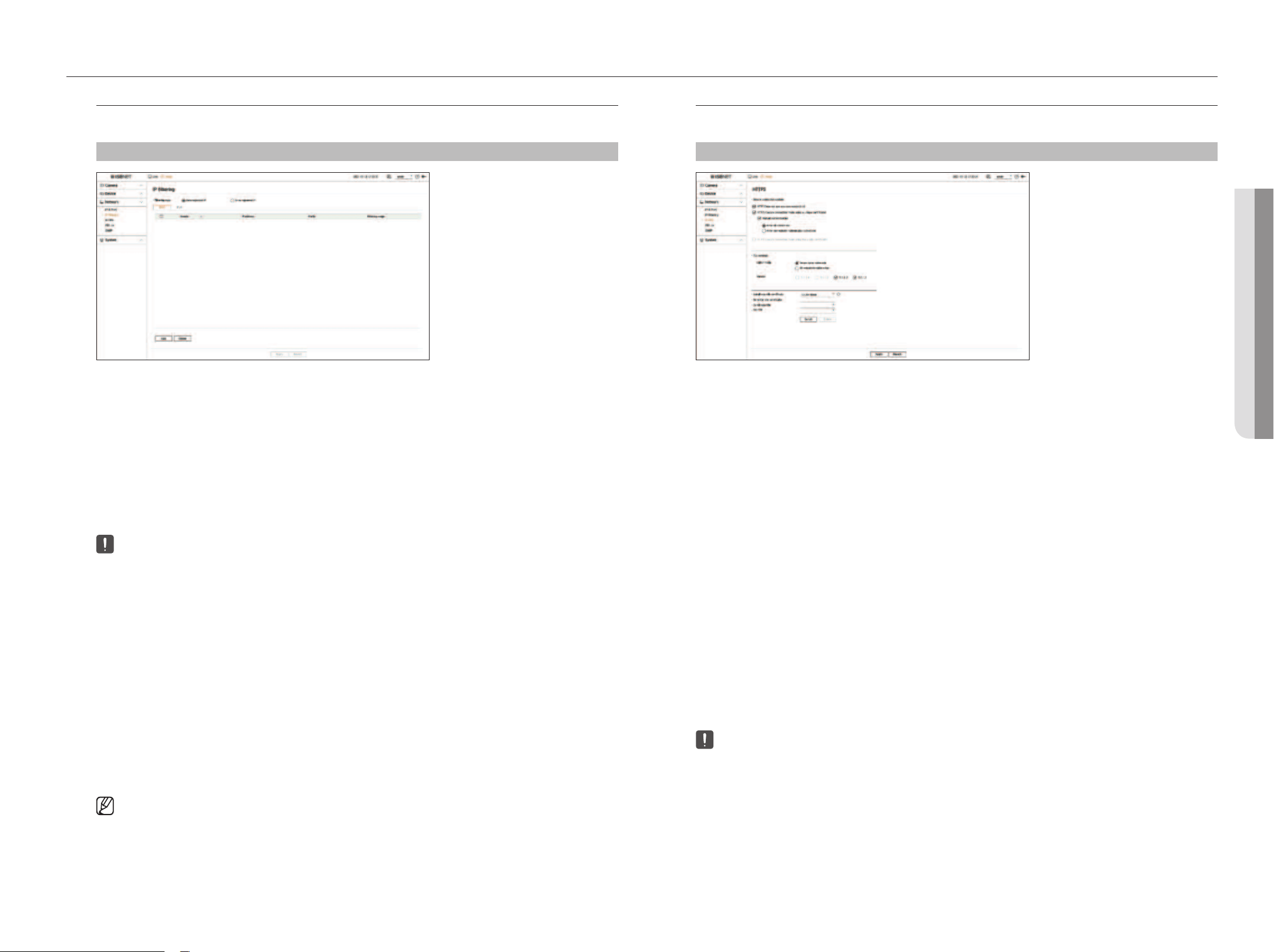
English _43
• SETUp
setup
• SETUp
hTTpS
You can choose a secure connection system or install a certificate.
Setup > Network > hTTpS
●
Secure connection system: You can select a secure connection system according to your environment
considering the level of security.
HTTPS (HyperText Transfer Protocol Secure) is a version of HTTP with advanced security. It uses TLS (Transport
Layer Security) to exchange data in the process of encrypting/decrypting the user's page request.
– HTTP (Does not use a secure connection): Transmits data without encryption.
– HTTPS (Secure connection mode using a unique certificate): A secure connection is made using a unique
certificate provided by the decoder.
■
Mutual authentication: Mutual authentication can be performed to enhance security. If you select <Allow all connections> you can access
the decoder without mutual authentication. If you select <Allow only mutually authenticated connections> you can access the decoder
only when mutual authentication is successful.
– HTTPS (Secure connection mode using the public certificate): A secure connection is made using the public
certificate. You can select it after installing the public certificate.
●
TLS settings: You can select the Cipher mode or TLS version to use for encrypted communication.
– Cipher mode: Provide cipher suites by combining different algorithms to be used in TLS encrypted
communication, such as key exchange, authentication, and encryption.
<Secure cipher suites only> only uses cipher suites with high security.
When considering backward compatibility, select <All compatible cipher suites>. However, since it
includes all cipher suites regardless of security status, it may be vulnerable.
– Version: Select the TLS protocol version to be used for encrypted communication.
■
If you select <Secure cipher suites only> for <Cipher mode> you can only select from among <TLS 1.2> or <TLS 1.3>.
■
In case a decoder is connected to the external internet, or is installed in an environment where security is important, we recommend using the
HTTPS connection.
●
Install Public Certificate: You can scan and register a public certificate to be installed. You need to install
certificate files and key files issued by the certification institution to install a certificate. Click <Install> to
register the certificate.
■
You cannot install or delete public certificates when they are in the <HTTPS (Secure connection mode using the public certificate)> mode.
Change to <HTTP (Does not use a secure connection)> or <HTTPS (Secure connection mode using a unique certificate)> mode to
proceed.
■
Install the certificate file format as .crt and the key file format as .key.
■
Use the PEM format generated by RSA (2048 or higher recommended) or ECC for certificate and key files.
■
Use PKCS#1, PKCS#8 without password for certificates and key files.
Ip filtering
You can create a list of IPs to allow or deny access to a specific IP.
Setup > Network > Ip filtering
●
Filtering type
– Deny registered IP: Deny access to the registered IP.
– Allow registered IP: Allow access only to the registered IP.
●
Enable: Select whether to enable registered IP filtering.
●
IP address: Displays the registered IP address. Double click the IP address to change the settings.
●
Prefix: Display the prefix to be filtered. Double-click the prefix to change the settings.
●
Filtering range: If you enter an IP address or prefix, it displays the range of IP addresses that are allowed or
denied.
■
In case a camera is included in the denied items or not included in the allowed items, access to the camera is blocked.
■
For IPv4, camera IP filtering through PoE port is not immediately applied. (Previous connections are maintained, and filtering is applied on next
login.)
To register the Ip addresses to filter
1. Select the IP type tab you want to register from IPv4 or IPv6.
2. Click <Add> at the bottom of the screen.
3. When the additional window is displayed, set the details.
●
IP filtering: Select whether to use IP filtering.
●
IP address: Enter an address to use for IP filtering.
– Enter a value within the range of 0 - 255 for an IP address to register.
●
Prefix: Enter a prefix value.
4. Click <Ok> to complete.
■
To delete a registered item, select the check box of the item to be deleted and click <Delete> at the bottom of the screen.
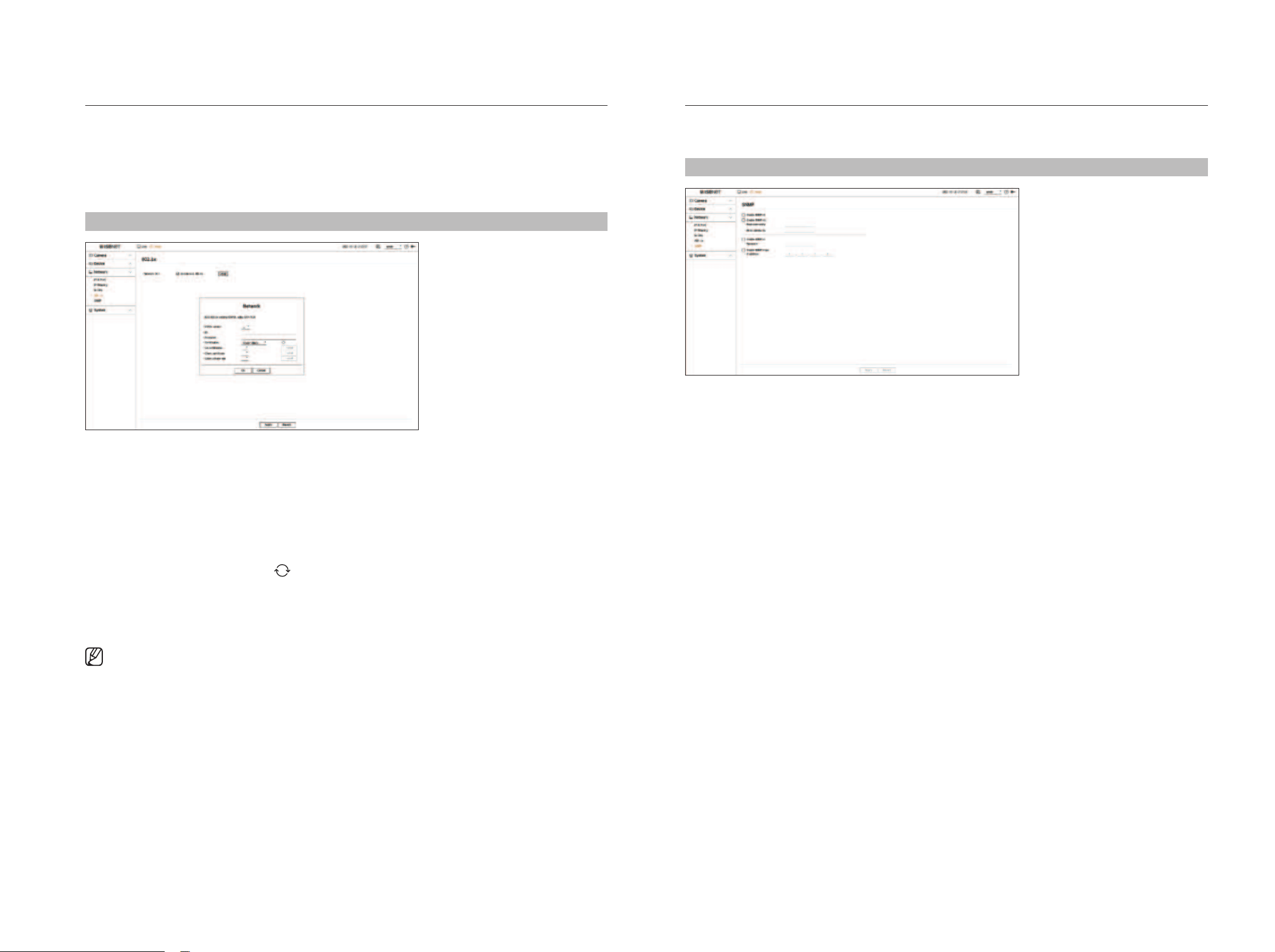
44_ setup
802.1x
When connecting the network, select whether to use the 802.1x protocol and install the certificate.
802.1x is an authentication system between a server and a client, which prevents hacking, virus infection, and
information leakage of transmitted and received network data.
802.1x can be used to block unauthorized client access and increase security by allowing only authenticated
users to communicate.
Setup > Network > 802.1x
●
EAPOL version: Select the EAPOL version to be used as protocol.
■
Some switch hubs will not operate if you set them to version <2>. Select the version <1>, which is the EAPOL default.
●
ID: Enter the ID provided by the RADIUS server administrator.
■
If the entered ID does not match the ID of the client's certificate, it won't be processed properly.
●
Password: Enter the password provided by the RADIUS server administrator.
■
If the password you entered does not match that of the client's private key, it won't be processed properly.
●
Certificates: Search for a device. Click <
> to re-search the device.
●
CA certificates: Select if the public certificate includes a public key.
●
Client certificate: Select if the public certificate includes a client's authentication key.
●
Client private key: Select if the public certificate includes a client private key.
■
For successful implementation of the 802.1x operating environment, the administrator must use the RADIUS server.
In addition, the switch hub connected to the server must be a device that supports 802.1x.
■
If the time setting of the RADIUS server, switch hub, and decoder do not match, communication between devices may not be possible.
■
If a password is assigned to the client's private key, the server administrator should confirm the ID and password.
The ID and password allow up to 30 characters each. Please note that it only supports letters, numbers and special characters ("-", "_", ".” ) only.
Accessing non password-protected files is allowed without entering a password.
■
The protocol of a decoder that supports the 802.1x is EAP-TLS.
■
You need to install all three certificates to use 802.1x.
SNmp
The SNMP protocol allows system or network administrators to remotely monitor and configure the network
devices.
Setup > Network > SNmp
●
Enable SNMP v1: Use SNMP v1.
●
Enable SNMP v2c: Use SNMP v2c.
– Read community: Enter the name of the read-only community to access the SNMP information.
– Write community: Enter the name of the write-only community to access the SNMP information.
●
Enable SNMP v3: Use SNMP v3.
– Password: Set the initial user password for SNMP version 3.
●
Enable SNMP traps: Use SNMP traps to send important events and statuses to the management system.
– IP address: Enter the IP address to send messages.
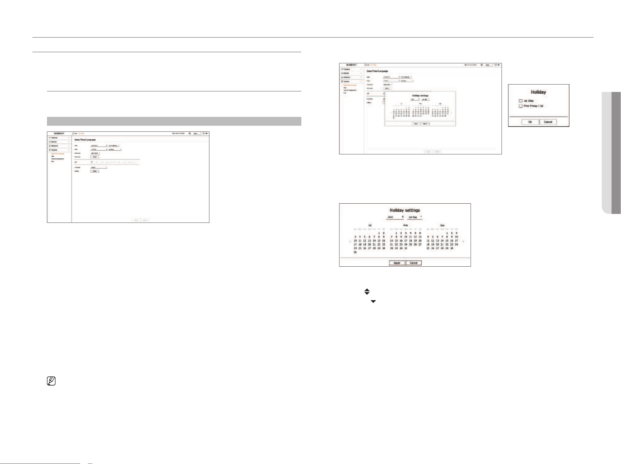
English _45
• SETUp
setup
• SETUp
SETTINg ThE SySTEm
You can set the date, language, authority, etc. displayed when using the system, and query system information or log
information.
Date/Time/language
You can check and set up the current Date/Time and time-related properties, as well as the language used for the
interface on the screen.
Setup > System > Date/Time/language
●
Date: Sets the date and its format that will appear on the screen.
●
Time: Sets the time and its format that will appear on the screen.
●
Time zone: Set the time zone of the area where the decoder is installed based on Greenwich Mean Time (GMT).
■
GMT (Greenwich Mean Time) is standard World Time and the basis of the world time zone.
●
Time Sync: Specify the use of synchronization with the time server.
Click the <Setup> button to display time sync setup screen.
If you use <Synchronize with NTp server> the current time of the decoder is synchronized by the server
designated by the <NTp Server address>, and you cannot change time information manually.
– Synchronize with NTP server: Select whether to synchronize time with the time server.
– NTP server address: enter an IP address or URL address to be used as a time server.
– Last sync: Display when it was last synchronized to the time server currently set.
– Enable as NTP server: If you select <Enable> the decoder operates with the time server of another decoder
or network camera.
●
DST: Set up Daylight Saving Time with its period to make the time earlier than the GMT of its time zone by 1
hour during the set period.
●
Language: Select your language. Sets the language for the interface.
■
Depending on the location of the product release, the language and standard time setup may vary.
●
Holiday: A user can select specific dates as holidays according to their own preferences. Select a holiday from
the calendar displayed by clicking <Setup>.
Example) If you select July 1 and only check <Jul 1Day>, July 1 is set as a holiday every year; if you select both
<Jul 1Day> and the <first friday | Jul> July 1 and the first Friday of July are set as holidays every year.
To use the calendar
1. Select year and month.
■
Click < > on the right side of the year to change the year by one year.
■
Click the < > to the right side of the month to change the month every 3 months.
2. Select the date and click <Apply>.
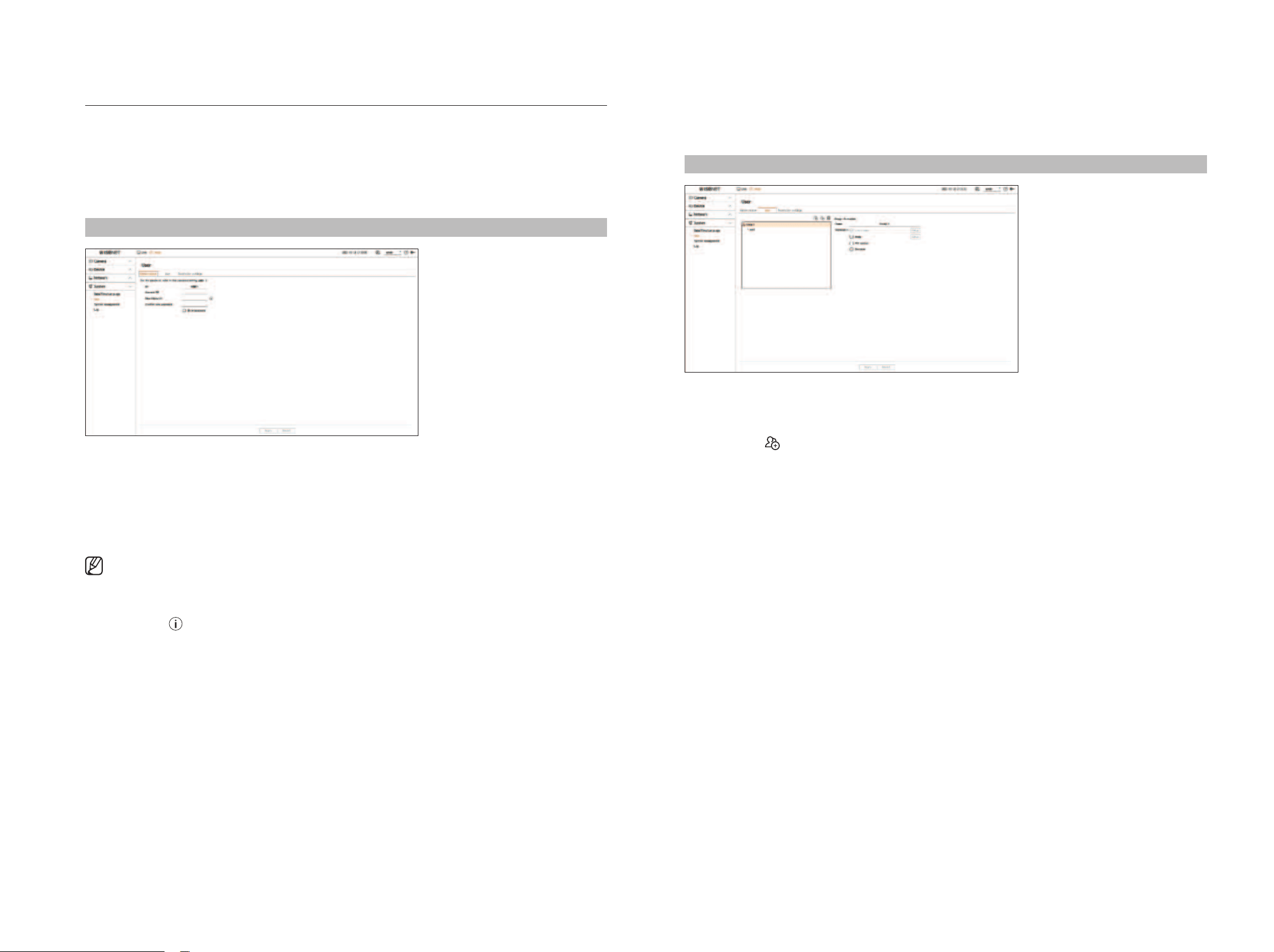
46_ setup
User setting
You can create user groups and set authorities for each group. You can manage user information such as
registering and deleting users in the created user group.
Setup > System > User > User
To add a group
1. Click on the <
> button to launch the Add Group popup window.
If you want to add a group, click on <Ok>.
2. If you click the Group Name item on the right, a virtual keyboard to enter the group name will appear.
Enter the group name to register.
■
You can add a maximum of 10 groups.
To set group permission
Set the access authority of the group.
Users in the group can only enable the menu to which they have been granted authority.
1. Select the menu to set group permissions.
●
Live channel: You can set permissions to access the live screen for each channel.
●
Menu: You can select the setup menu which a user from a group can access.
If you check <menu> the "menu permission" pop-up window will appear. Select the desired channel and
click <Ok>. Click <Setup> to change the selected item.
●
PTZ control: A user from a group can control the PTZ camera.
●
Shutdown: A user from a group can shut down the system.
■
Permission-set menus will show up in the Live menu when users of the group login.
2. Select <Apply>.
Users in the group will be given access to the set items.
User
You can manage users, such by adding or deleting users and granting different authority to each user.
Setting the Administrator
You can set or change the ID and password of the administrator. The administrator can use and set all menu items
and functions.
Setup > System > User > Administrator
●
ID: Change the ID of the administrator.
●
Current PW: Enter the current password.
●
New Password: Enter new password.
●
Confirm new password: Enter the password again to be set as new.
■
If you check <Show password>, the encrypted password will be shown as the actually entered characters.
■
The initial administrator ID is set to “admin” and you will need to configure the password in the installation wizard.
■
Please change your password periodically every three months to safely protect personal information and to prevent damage through
information theft.
Please note that the user is responsible for their security and any other problems caused by mismanaging a password.
■
If you click < >, a basic guide for password setup is displayed.
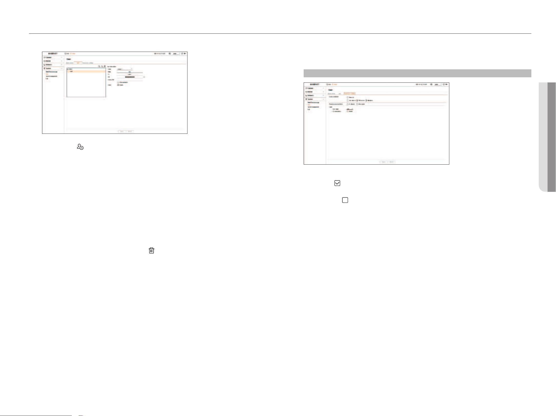
English _47
• SETUp
setup
• SETUp
To register a user
1. Click on the < > button to launch the user addition popup window.
To add a user, click on <Ok>.
2. Select a group.
When registering a user, the selected group will be automatically registered.
■
You can change the group after entering all the user information.
3. Enter a name, ID, and password (confirm password) and enable or disable the viewer option.
If you activate the use of
<
Viewer
>
, you will have the right to use the web viewer and the network viewer.
■
If you check <Show password>, the encrypted password will be shown as the actually entered characters.
4. Click
<Ok>.
Registered user information will be saved.
To delete the group and user information
1. Select the group or user to delete and press the <
> button.
2. The deletion confirmation window will appear and click on
<
Ok>
.
Setting permissions
Set user's restricted access or network restriction.
Items with restrictions will require logging in for use.
Setup > System > User > Restriction settings
●
Access restriction: Select a menu that you wish to restrict access to a user.
– Checked (
): Restricted
■
Only users who are authorized to access the menu in <User> can access the menu.
– Not checked (
): Accessible
■
All users can access the menu, regardless of the permission settings in <User> for the menu.
●
Remote access restriction: Restrict remote access for users.
– All viewers: Restrict network access and access to the web viewer of all users.
– Web viewer: Set all users to be unable to access the web viewer.
●
Auto logout: If a user does not operate the decoder for a set period of time after logging in, the user is
automatically logged out.
●
ID manual entry: Select whether to manually enter the ID into the log-in window.
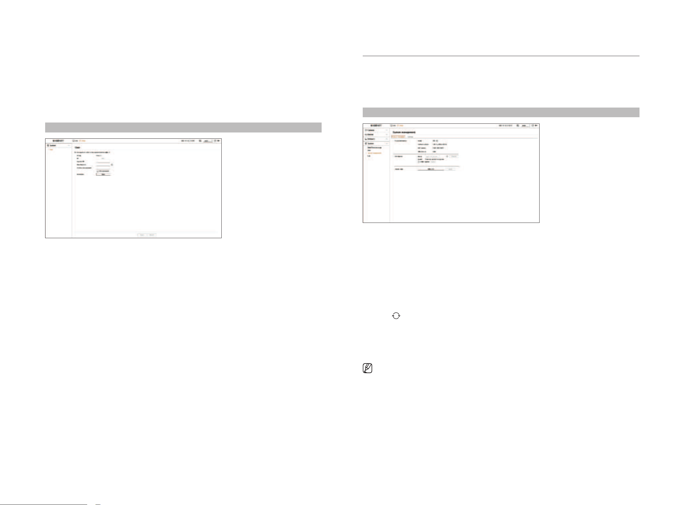
48_ setup
System management
You can check the current system version and update it to a new version, export data, reset settings, and more.
Checking the System information
You can check the current version of a system and MAC address and upgrade it.
Setup > System > System management > product information
●
Product information: Display the information of the current system.
– Model: Display the model name of a product.
– Software version: The software version of the product currently being used is displayed. You can check the
software version and upgrade to the latest version.
– MAC address: Display the MAC address of a product.
– UWA Version: Display the UWA Version of a product.
●
S/W Upgrade: Upgrade the software of the searched decoder to the latest version.
– If it is not normally connected, the software upgrade item will not be displayed.
– Click <
> to search software in the USB or network.
– When the updating is done, it automatically reboots. Be careful not to turn off the power during the
upgrade.
●
Device name: Enter the name of a device. We recommend naming devices differently to distinguish multiple
decoders in VMS and Device Manager.
■
The system information displayed may vary depending on the decoder model.
If the user has restricted access
If a general user selects a menu to which they do not have access, an access restriction confirmation window will
be displayed. If all rights are restricted, only the accessible menu of the live screen menu will be displayed, and
only the user's own password can be changed.
To change the user password
If you log in with the user account of a group with restricted access, you just can change your own password.
Setup > System > User
1. Provide the login information.
2. Select <
User>
from
the
<System
>.
3. Please enter your current PW.
4. Provide a new password. Enter the password you want to change in the password confirmation box again.
5. Select
<Apply>
.
The old password will be changed to a new one.
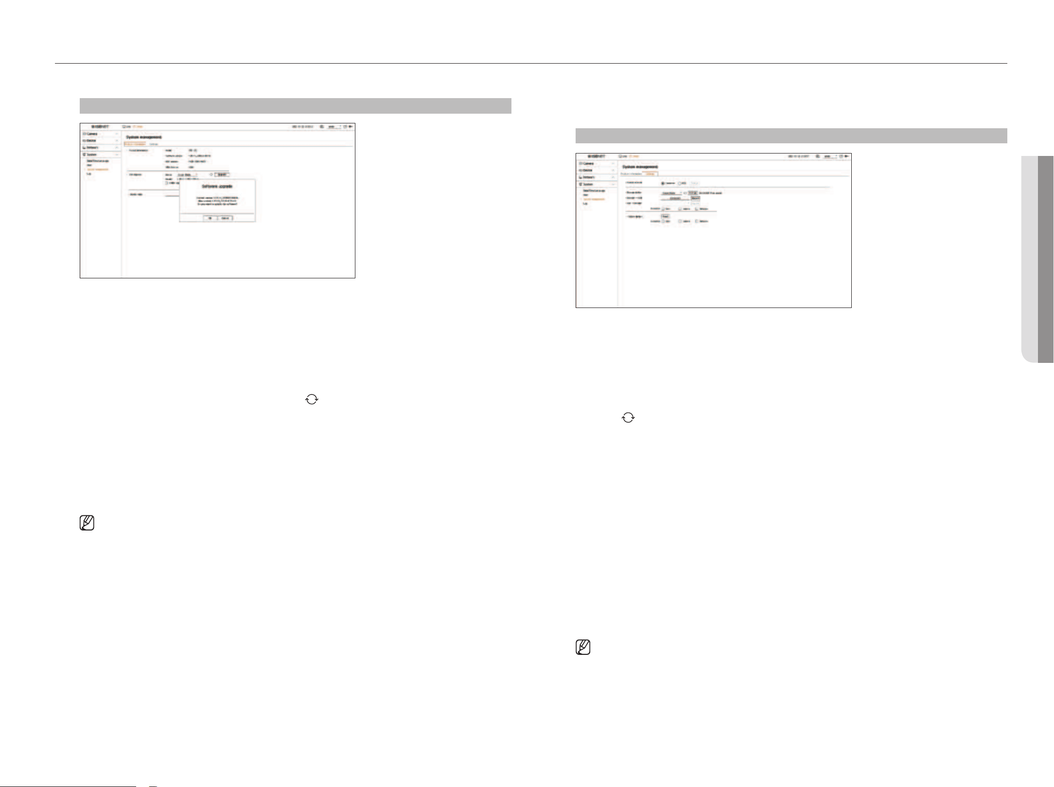
English _49
• SETUp
setup
• SETUp
To upgrade the current software version
Setup > System > System management > product information
1. Connect a device storing the software to be updated.
■
It may take about 10 seconds to recognize the device.
■
Upgradeable devices include USB memory and network device.
■
If you want to upgrade it on the network, the product should be connected to an external network.
Upgrade via the proxy server may not be enabled due to the restricted access.
2. When the recognized device appears, select
<Upgrade
>
.
■
If you connect a device in the upgrade menu window, you can press the
<
> button to search for available software.
■
If there is an upgraded version on the network, a popup window will appear.
■
<Upgrade> will be activated only when there is a higher version than the current software version.
3. Click
<
Ok
>
on the <Software upgrade> window.
■
While upgrading, it shows the progress.
4. When the upgrading is done, it automatically restarts.
Do not turn the power off until it finishes restarting.
■
Restart from the stage 2 if the "Upgrade failed" window appears. When you experience continued failure, consult the service center for
assistance.
managing setup information
You can set the operation mode to control the decoder. In addition, you can apply the same settings in use to
other decoders or initialize the product.
Setup > System > System management > Settings
●
Operation mode: If you have admin permissions, you can select operation mode to control a decoder.
– Standalone: Can control Live monitoring and the setting changes of the camera on a decoder.
You can only change admin account information and operation mode in the web viewer.
– WEB: Can only Live monitor the camera on the decoder, and requires the web viewer to change settings or
control.
●
Storage device: Display the connected storage device.
– Click <
> to see the storage device.
– If you click the <format>, the format confirmation window will appear. Click on the <Ok> button to format
the selected storage device.
●
Decoder → USB: Store the information set on the decoder to the storage device.
– If you select <Export> the confirmation window will appear. If you select <Ok> then the decoder
information will be stored as a file.
●
USB → Decoder: Apply the setup information stored in the storage device on a decoder.
– If you select the exclusion setting, you can import all information but the selected information.
– If you select <Import> then you can import setup information stored in the storage device. If you select
<Ok> then the imported information is applied to a decoder.
■
The <Export> and <Import> settings can be used in the same software version only.
●
Factory default: You can reset the system settings to the settings at the time of purchase. However, logs won't
be reset. Anything selected under Exclusion Setting won't be part of the factory reset.
A confirmation pop-up will appear when you press the <Reset> button. Select the <Ok> button to reset the
selected items.
■
If you export the setup information, the setup information is stored as a file in a decoder folder of the storage device.
■
If you want to import setup information, you must have a setup information file in a decoder folder of a storage device.
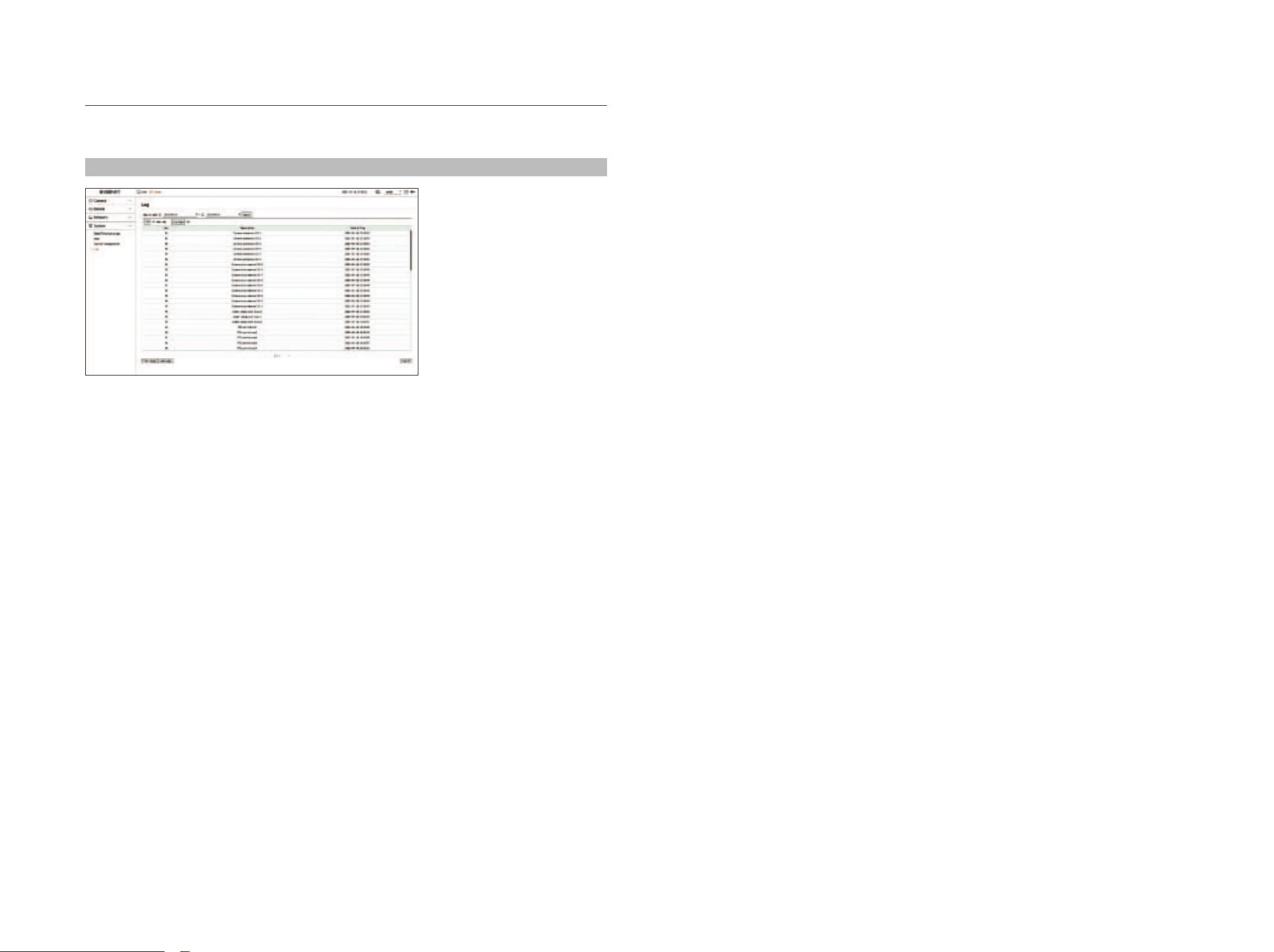
50_ setup
log
System Log shows log and timestamp on every system start up, system shutdown, and changes on system
settings.
Setup > System > log
●
Search date: You can use the calendar window which appears when using the calendar icon or the direction
buttons to select the date to search the system log.
●
Search: Specify the date and press this button to display the search result in the log list.
●
CH: Select a channel to search.
●
Log type: In case there is a lot of log information, you can conveniently search for the necessary information by
selecting a log type. Select the desired type and click <Apply>.
●
First page / Last page: If you have a lot of search results, you can move to the first or last page.
●
Export: Store all log information recorded on a decoder to a storage device.
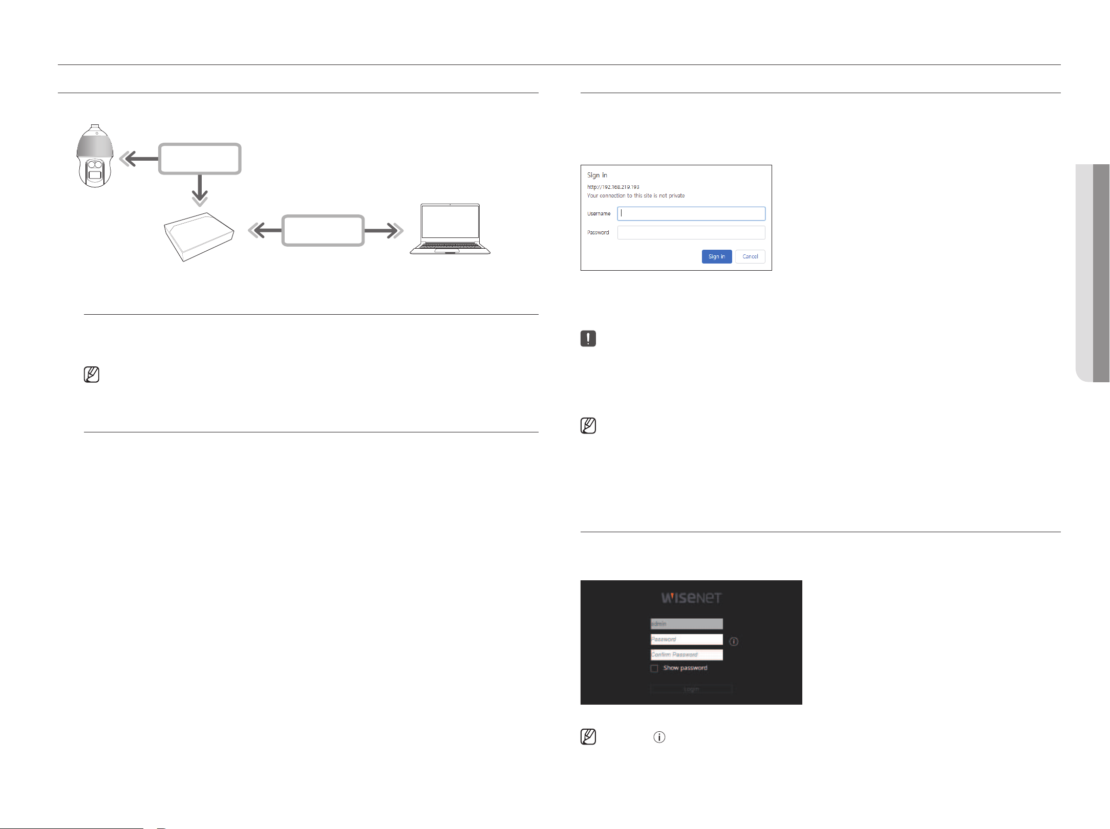
English _51
• STARTINg WEb VIEWER
starting web viewer
WhAT IS WEb VIEWER?
The web viewer is a software program that the operator can access remotely to change the decoder setup.
NETWORK
NETWORK
Decoder
Network Camera
Remote PC
Key functions
●
Remote connection using the browser
●
Split mode supported
■
Depending on the number of channels supported by the product, the number of screen split modes may vary.
System Requirements
The following lists the minimum suggested hardware and operating system requirements needed to run the Web
Viewer.
●
Use the browser recommended by the OS.
Example) Microsoft recommended browser: Microsoft Edge
●
Supported browsers: Chrome, Edge, and Safari
●
Supported OS: Works on all of the Windows, Linux, and OS X environments given the platform-independent
nature of the web.
●
Tested environments: Tested and certified to run on Windows® 10 with Edge 91, Google Chrome™ 91, and Intel®
Core™ i7-7700 processor 3.60 GHz with NVIDIA® GeForce® GTX™ 1050 or Intel™ HD Graphics 630.
CONNECTINg WEb VIEWER
1. Open your web browser and type the IP address or URL of the decoder into the URL address box.
2. A user with admin permissions should enter the admin ID and password.
A registered user should enter the user ID and password.
3. After you log in, the Live Viewer main screen appears.
■
All settings are applied according to the decoder settings.
■
If you change the web port when connecting to the Web viewer, you may fail to access it since the applicable port is blocked. In this case, change the
port to a different port.
■
Please change your password every three months to safely protect personal information and to prevent damage from information theft.
Please note that the user is responsible for their security and any other problems caused by mismanaging a password.
■
Only an administrator or a single user can access the web viewer.
■
The passwords of the admin and general users can be changed in the <User> menu of the decoder.
■
General users should have set <Web viewer> under <Remote access restriction> to Enable before connecting to the Web Viewer.
For details, refer to the "Setup > Setting the System > User” page in the table of contents.
■
All settings are applied according to the decoder settings.
SETTINg ThE DECODER pASSWORD
After being updated to the factory default, the password must be set for the decoder to access the web viewer.
Enter the password of the admin account and click <login>.
■
If you click <
>, a basic guide for password setup is displayed. Refer to the password setup rules.
• STARTINg WEb VIEWER
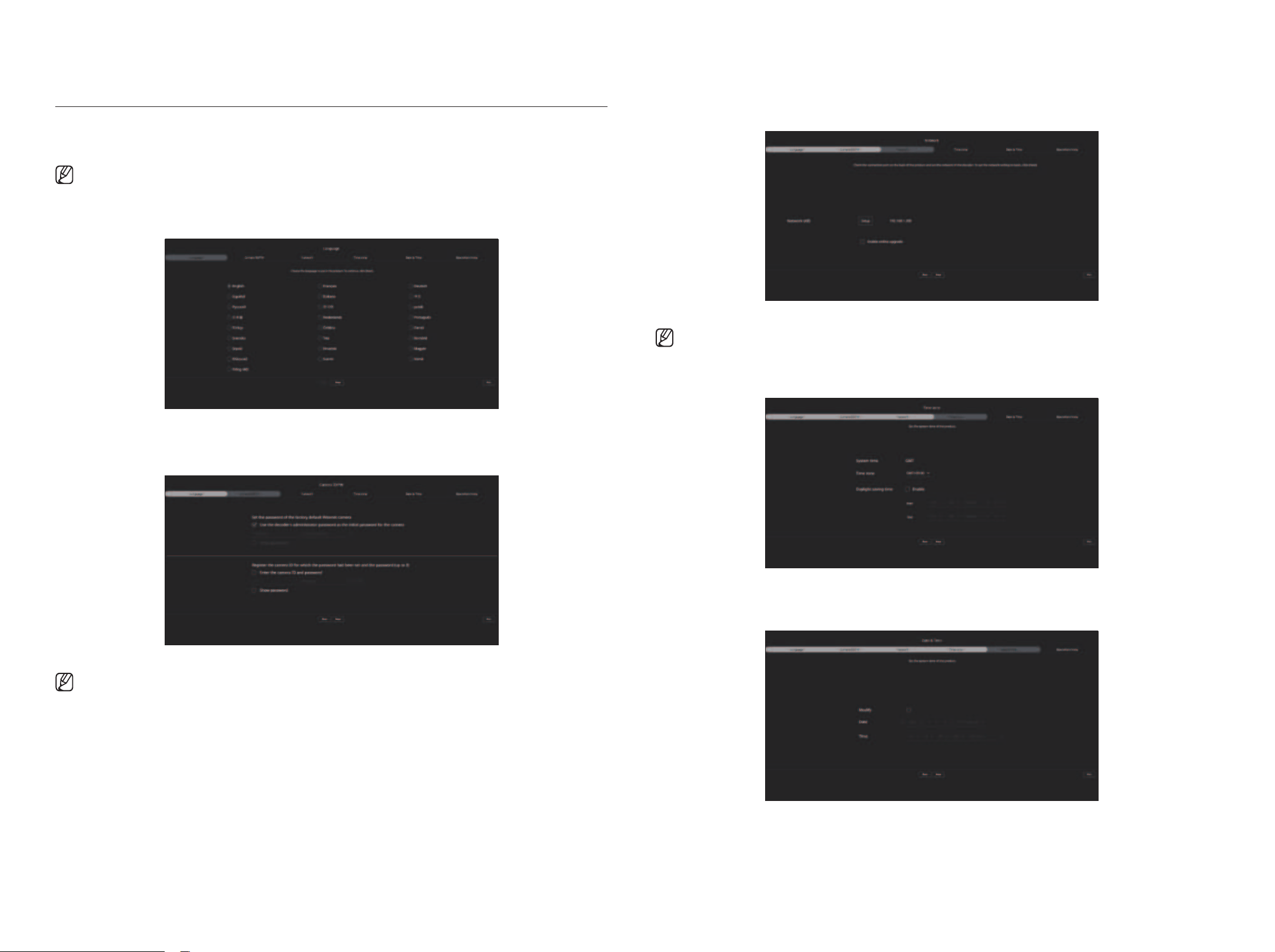
52_ starting web viewer
INSTAllATION WIzARD
As shown below, proceed through each step of the <Installation wizard>.
Installation Wizard can only be accessed at factory default status. If you do not want to proceed, click <Exit>.
■
When you complete the installation using the installation wizard on your decoder, the installation wizard will not appear on your web viewer.
1. On the <language> screen, select the language and press the <Next> button.
2. Set the camera password in factory default status on the <Camera ID/pW> screen.
If ID/PW is already set in the camera, register the ID/PW and click <Next>.
■
When the password is in factory default status, it can be changed and managed in a batch.
■
Up to 3 sets of camera IDs with passwords and passwords can be registered.
■
You may change the passwords of registered cameras all at once in the “Setup > Camera > Camera password” menu.
■
You cannot change the password for cameras registered with ONVIF and RTSP.
3. Set the network connection type and the connection environment on the <Network> screen, and then click the
<Next> button.
■
For details on network settings, refer to the "Getting Started > Installation wizard" page.
4. Set the daylight saving time on the <Time zone> and then click <Next>.
5. Select the <modify> checkbox to change the date and time on the <Date & Time> screen.
Set the date and time, and then click <Next>.
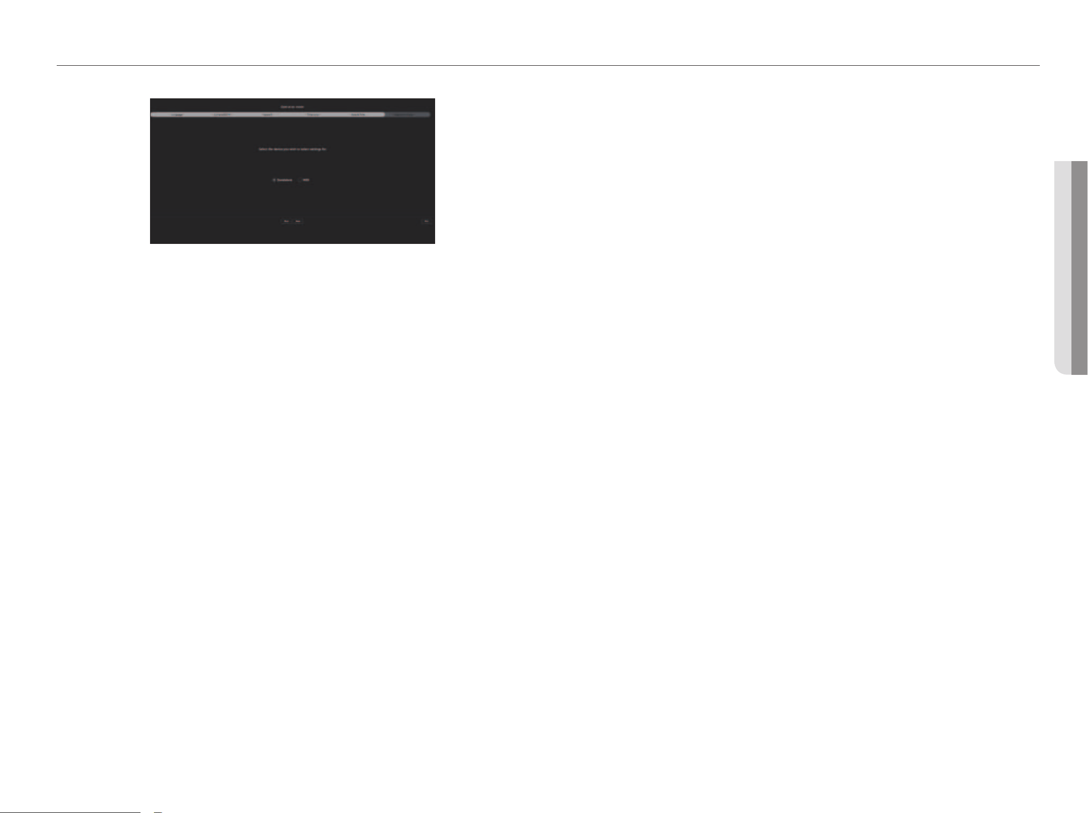
English _53
• STARTINg WEb VIEWER
starting web viewer
• STARTINg WEb VIEWER
6. Select an operation mode that can control the decoder from the <Operation mode> screen.
●
Standalone: Can control Live monitoring and the setting changes of the camera on a decoder.
You can only change admin account information and operation mode in the web viewer.
●
WEB: Can only Live monitor the camera on the decoder, and requires the web viewer to change settings or control.
7. Click the <Next> button to complete the installation wizard.
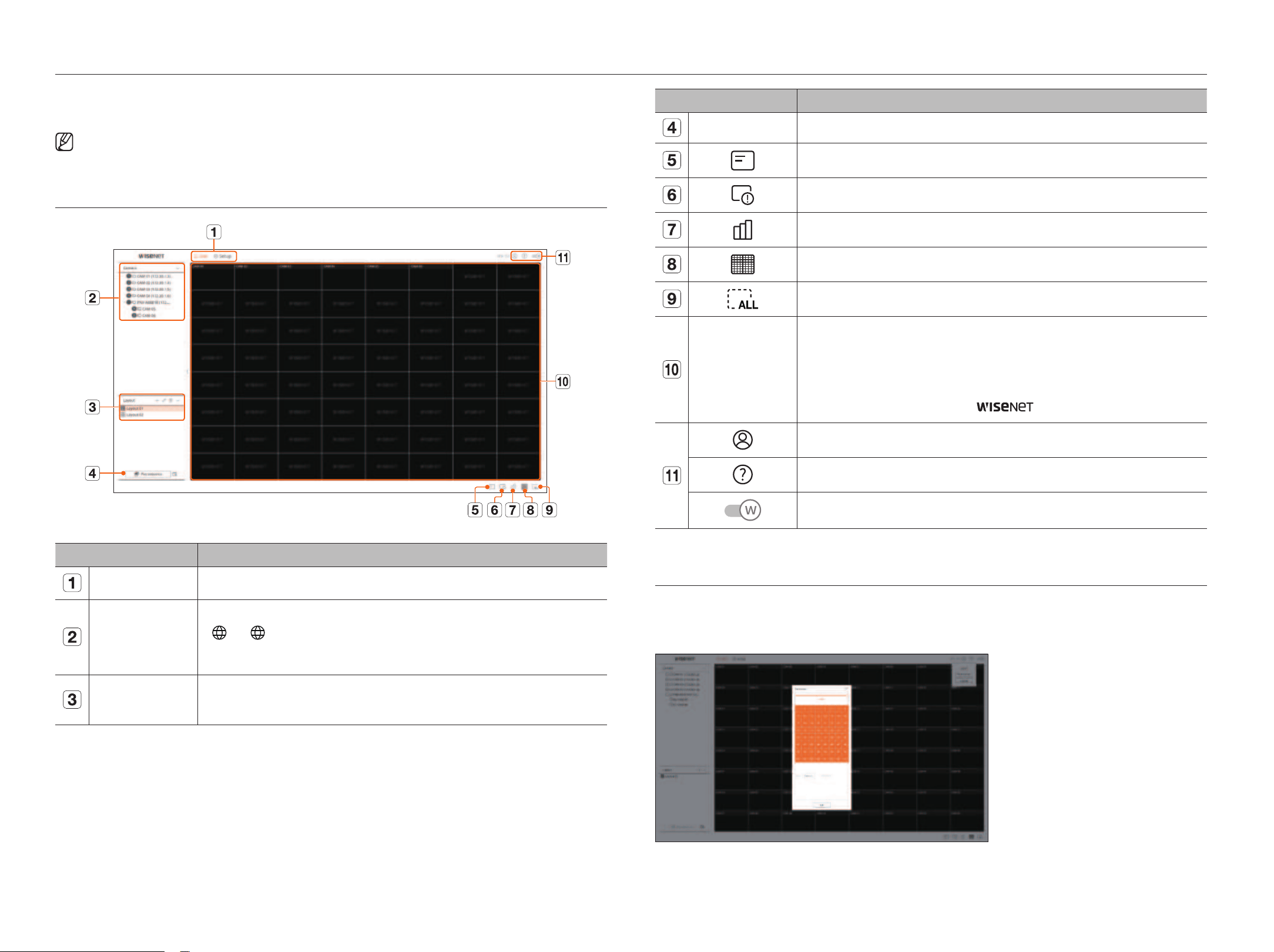
54_ live viewer
live viewer
Menu title Functions
Play sequence / Setup You can set and play sequences on the list of layouts.
Displays the information on the OSD screen in the video window.
Shows channel information.
Shows the status of all cameras connected to the decoder.
Sets the split mode of the video window.
Removes all screens from the video window.
Video window
Displays the camera registration status.
The layout set on the web viewer is reflected in real-time in the video window of the decoder.
You cannot check the video of the camera in the web viewer.
●
The camera name is displayed on the upper left side of the screen for channels in which cameras are registered.
●
For channels in which cameras are not registered, <
> is displayed at the center of the screen.
The ID of the connected user is displayed.
You will be directly connected to the Hanwha Techwin homepage (www.hanwha-security.com).
Changes the color theme of Web Viewer.
ChECKINg USER ID
Displays the user ID and authority for the user connected to Web Viewer.
Click <logout> to log out the logged-in user.
■
If you are logged in with an admin account, the authority setting window will not be displayed.
In the live viewer, you can change the camera registration status, settings of the layout and sequence playback, and split
mode.
■
You can check the following Live screen configuration when it is in <Standalone> operation mode.
SCREEN lAyOUT Of ThE lIVE VIEWER
Menu title Functions
Menu Clicking on each menu takes you to the corresponding menu screen.
Camera List
The list of cameras registered in the decoder is displayed.
●
: The < > icon is displayed when you mouse over the camera list. Click the icon to go to the camera web page.
To go to the camera webpage, you must have the right to set channels and profiles, set <Video> to <On> in the “Setup
> Camera > Channel setup" menu.
Layout List
This displays a list of the default layouts and the layouts that have been created.
The layout set on the web viewer is reflected in real-time in the video window of the decoder.
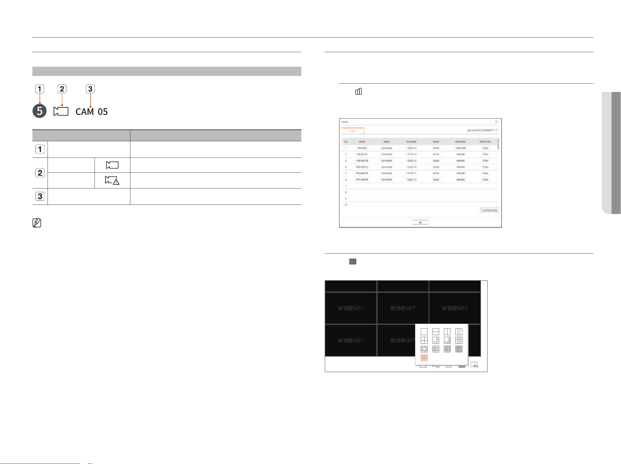
English _55
• lIVE VIEWER
live viewer
• lIVE VIEWER
ChECKINg ThE All CAmERA STATUS
You can check the status of all cameras connected to the decoder.
live Status
Click < >. You can check the status and transmission information of the camera connected to each channel.
■
To change the profile setup, click the <Camera setup> button. For details on how to set up the profile, refer to the "Setup > Setting the Camera >
Profile setup” page in the table of contents.
ChANgINg ThE pATTERN Of SplIT SCREEN
Click the <
> button and select the desired split screen.
The selected split screen is applied to the video window.
ChECKINg ThE CAmERA lIST
Displays the camera type, status, and name registered in the decoder.
live > list
Name Function Description
Channel information Displays channel information. (channel number, color indication on video window assignment).
Camera type Displays a normal camera.
Camera status
Displays the camera error status.
Camera name Displays the name set for the camera.
■
If a camera connection error occurs, it is disabled in the list.
■
The camera status displays information changes according to the network connection status and settings.
■
For multichannel cameras registered with the Wisenet protocol, the channel information will be displayed under the model name of the multichannel
camera.
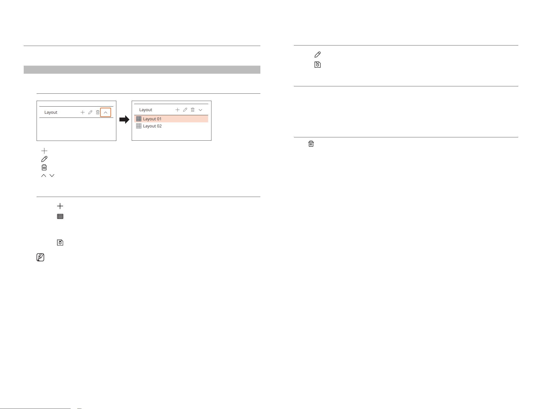
56_ live viewer
lAyOUT SETUp
This section outlines how to select a series of channels based on their purpose/accessibility and monitor them in a
single layout.
live > layout
Checking layout list
●
: Create a new layout.
●
: Change the channel or name of the layout.
●
: Delete the added layout.
●
/ : Open or close the layout list.
Adding layout
1. Click <
>.
2. Click <
> to select split mode.
3. Double-click or drag and drop a channel to display in the layout screen from the camera list on the video
window.
4. Click <
> to save the set layout.
■
Each layout is saved separately by the user.
Changing layout Names
1. Click <
> after selecting the layout to change the name.
2. Click <
> after changing the layout name.
Changing layout Channels
1. Double-click to select a layout you want to change the channel of.
2. To delete the channel, click the <x> displayed on the top right of the channel screen when you mouse over.
3. Double-click or drag and drop a desired camera from the camera list on the video window to add a channel.
Deleting layout
Click <
> after selecting the layout to delete.
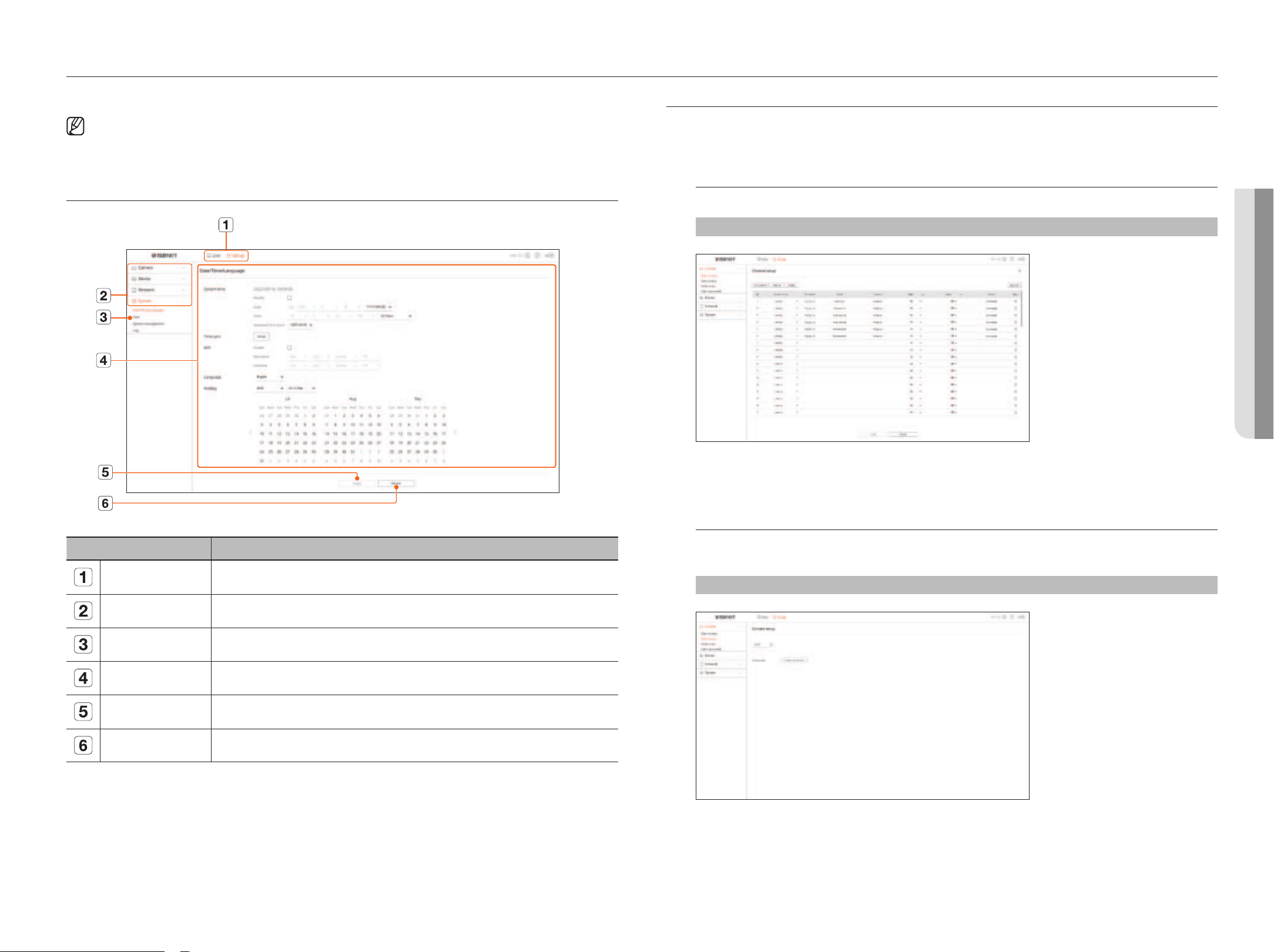
English _57
• SETUp VIEWER
setup viewer
• SETUp VIEWER
You can configure the decoder settings remotely on the network.
■
You can check the following set viewer screen configuration when it is in <WEB> operation mode.
■
You can only change the admin account information and operation mode in <Standalone>.
SCREEN lAyOUT Of ThE SETUp VIEWER
Name Functions
Menu Click each menu to go to the menu screen.
Top menu list Configure the settings or select a parent item to change the existing settings.
Sub-menu list Among the sub-menus of selected parent menu, select a desired item to set.
Detailed Menu Click desired item's input field to change and enter a desired value.
Apply Apply the modified settings.
Revert Revert to the settings used before the change.
SETTINg ThE CAmERA
You can search and set the camera connected to the decoder.
For details, refer to the "Setup > Setting the Camera" page in the table of contents.
Channel setup
You can register a network camera for each channel and make connections between them.
Setup > Camera > Channel setup
●
When you click the <Upgrade> button, you can check the camera’s version, upgrade version, and status, and
perform an upgrade.
Camera setup
You can change the video settings of a registered network camera for each channel by connecting to the Camera
webviewer.
Setup > Camera > Camera setup
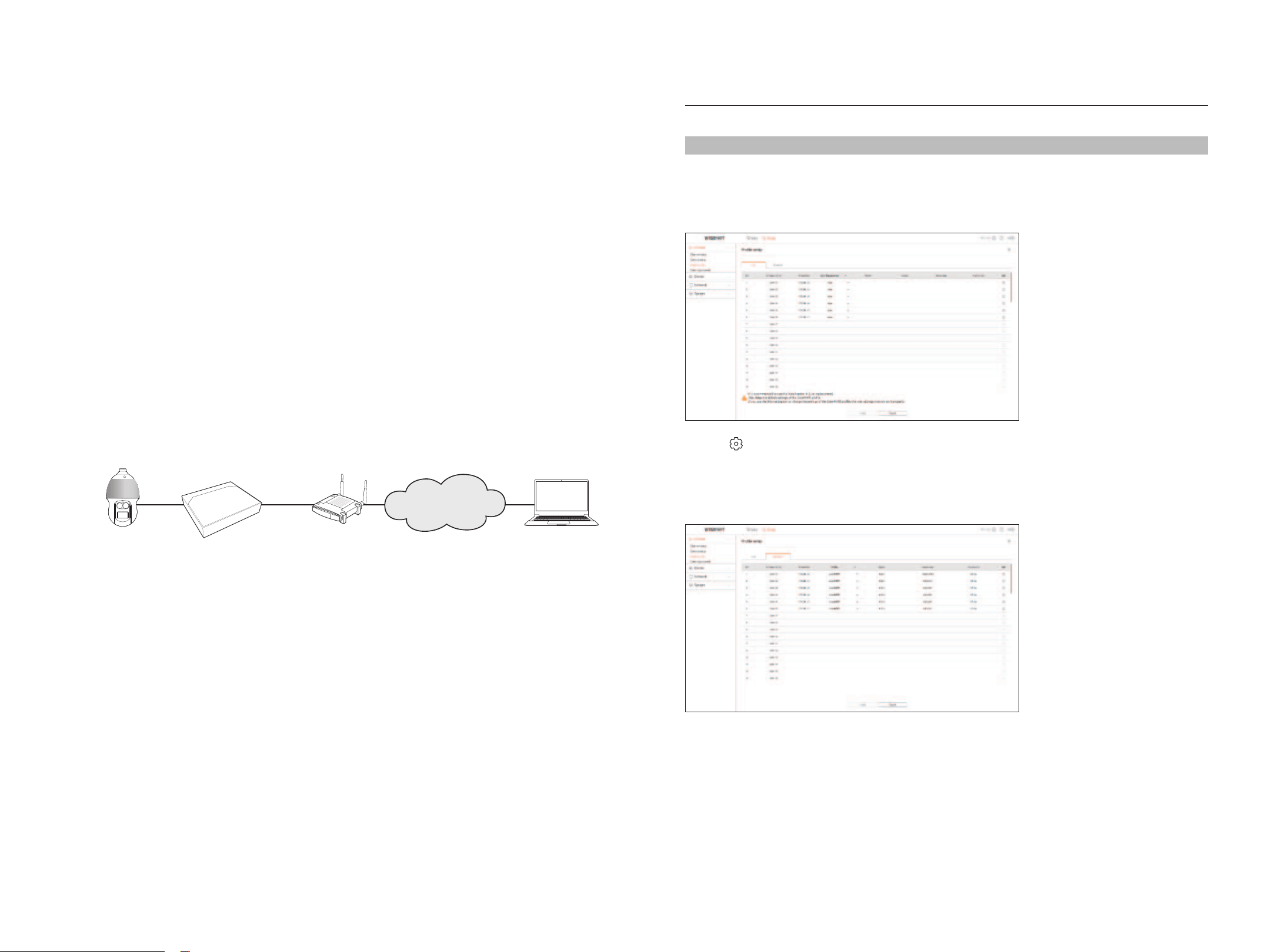
58_ setup viewer
●
When you click the <Camera webviewer> button, a new camera web browser window will be run.
– This is not supported if the camera is connected to the RTSP protocol.
– This is not supported if the camera is connected to DDNS or a URL.
– It supports the version specified below or later for each Q/P/X series camera.
(QND-7010R series: 1.04, QND-7080R series: 1.02, QND-6010R series: 1.02,
QND-6070R series: 1.01, P series: 1.01)
– When you are connecting to the camera web page on a closed network, a camera that does not support the
universal web will not be able to output an image.
– The cam proxy port's default settings are automatically set in sequence as many as the number of channels
supported by the decoder. If you want to change the proxy port, then select the port setup menu.
– 4-channel (10001-10004), 8-channel (10001-10008), 16-channel (10001-10016), 32-channel (10001-10032),
64-channel (10001-10064)
Example) Defaults of cam proxy ports for each product
●
4-channel model: 10001--10004
●
8-channel model: 10001--10008
●
16-channel model: 10001--10016
●
32-channel model: 10001--10032
●
64-channel model: 10001--10064
– When connecting outside the closed network as shown in the figure, the port forwarding setting of the
camera proxy port is required for the router.
Decoder
Network Camera
IP Router
Remote PC
Internet
– If there are multiple decoders within the closed network, each cam proxy port should be set using a different
port.
– If DDNS and Quick Connect are enabled, port forwarding will be automatically set.
– Chrome, Edge and Safari (Mac OS) browsers are supported.
profile setup
You can set the profile for a network camera.
Setup > Camera > profile setup
live
You can change the live transfer settings of the network camera.
●
Click < > to connect to the camera webviewer and change the settings.
Remote
You can set the video profile transmitted to the network and the secondary monitor.
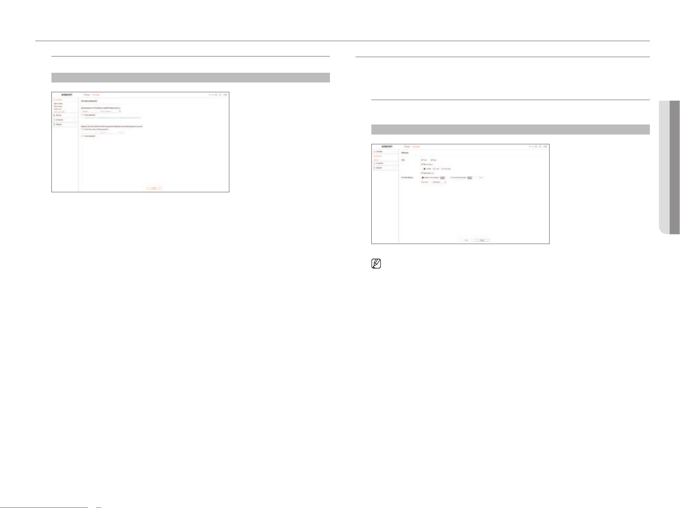
English _59
• SETUp VIEWER
setup viewer
• SETUp VIEWER
Camera password setup
You can change the passwords of all registered cameras at once.
Setup > Camera > Camera password
SETTINg ThE DEVICE
Can make detailed settings related to the monitor.
For details, refer to the "Setup > Setting the Device" page in the table of contents.
monitor
You can set the information displayed on the monitor the information location as well as the video output
method.
Setup > Device > monitor
■
If the screen does not work properly, see “Troubleshooting (FAQ)” in the Appendix.
■
You can set the monitor connected to the decoder in the Monitor Setup.
■
Video exceeding 1080p resolution will not be displayed from the extended monitor.
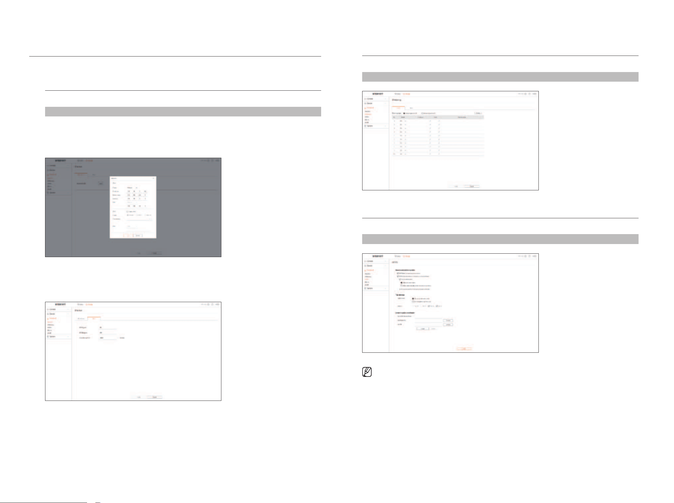
60_ setup viewer
SETTINg ThE NETWORK
For details, refer to the "Setup > Setting the Network" page in the table of contents.
Ip & port
A remote user can access the decoder via the network to check the current mode and the IP address.
Setup > Network > Ip & port
Ip address
Specify the network connection path.
port
You can configure the protocol related settings.
Ip filtering
You can prepare a list of IP addresses to allow or deny access to a specific IP address.
Setup > Network > Ip filtering
hTTpS
You can select a secure connection system or install public certificates.
Setup > Network > hTTpS
■
While enabling HTTPS, if you want to switch to HTTP, then abnormal operations can take place as the browser is saving the setting values. You
need to change the URL to HTTP and reconnect or initialize the cookie setting of the browser for normal operation.

English _61
• SETUp VIEWER
setup viewer
• SETUp VIEWER
802.1x
When connecting to a network, you can select whether to use the 802.1x protocol and install a certificate.
Setup > Network > 802.1x
SNmp
Using the SNMP protocol, the system or network administrator can remotely monitor the network devices and
set the environment.
Setup > Network > SNmp
SETTINg ThE SySTEm
You can configure the various settings of the decoder system.
For details, refer to the "Setup > Setting the System" page in the table of contents.
Date/Time/language
You can check and set up the current Date/Time and time-related properties, as well as the language used for the
interface on the screen.
Setup > System > Date/Time/language
System time
Set the date and time.
Time sync
Set the time synchronization.
DST
Daylight Saving Time (DST) is a time that advances clocks one hour forwards from the standard local time zone.
language
Select a language to be displayed on the decoder.
holiday
A user can select specific dates as holidays according to their own preferences.
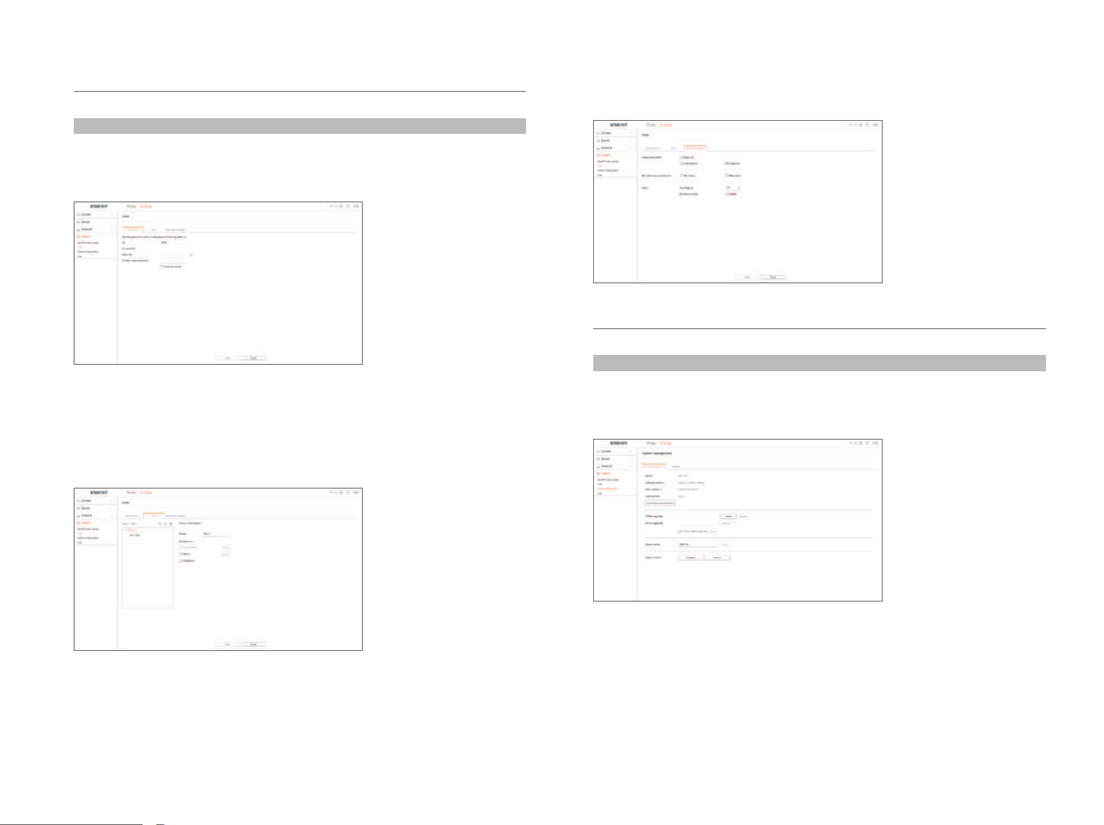
62_ setup viewer
User
You can manage users, such by adding or deleting users and granting different authority to each user.
Setup > System > User
Administrator
You can change the admin ID or the password.
■
Only alphanumeric characters are allowed in the ID.
■
If you access with a user ID instead of an admin ID, you cannot change the ID.
■
If the ID being used is changed, you will be automatically logged out.
User
You can add, change or remove a user or users.
Restriction settings
You can set the user's permission.
System management
You can check the current system version and update it to a new version, export data, reset settings, and more.
Setup > System > System management
product information
You can check the current software version and MAC address before proceeding with the software upgrade.
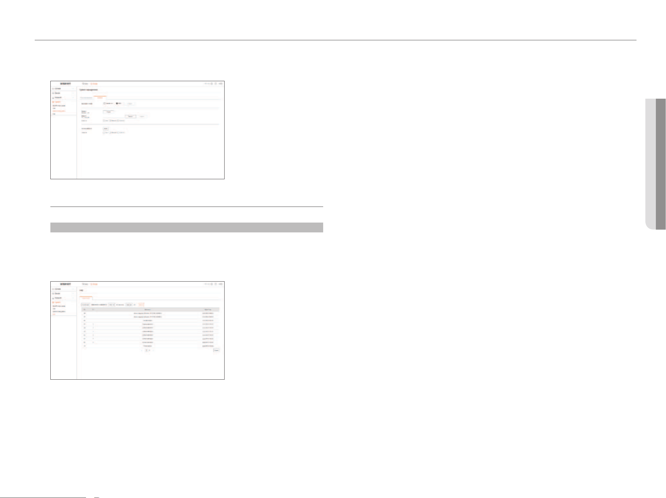
English _63
• SETUp VIEWER
setup viewer
• SETUp VIEWER
Settings
You can set the operation mode to control the decoder. In addition, you can apply the settings in use to other
decoders or initialize the product. Items in the <Exception> category are excluded from the initialization.
log
You can check the log information related to the system.
Setup > System > log
System log
System Log shows log and timestamp on every system start up, system shutdown, and changes on system
settings.
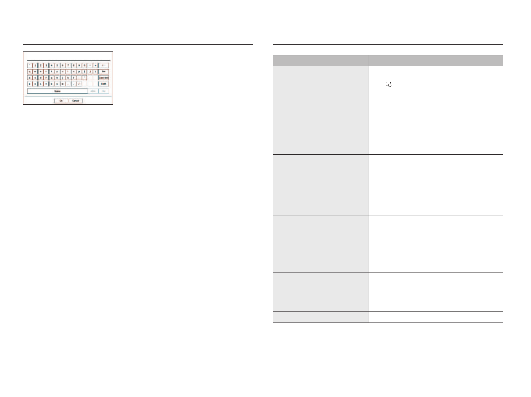
64_ appendix
appendix
USINg VIRTUAl KEybOARD
1. For alphanumeric inputs, the virtual keyboard window appears.
2. Using a mouse, click on the desired character tab.
3. Select
<
Ok
>
.
Entered words are applied.
■
If you want to enter the upper case and special characters, select <Caps lock> or <Shift>.
■
Using the virtual keyboard is the same to a normal keyboard use in your region.
■
Your ID can contain any combination of upper and lowercase alphabets and numbers.
■
If the password length is 8 to 9 digits, you can combine at least three different types of the following characters: upper and lowercase alphabets, numbers,
and special characters.
■
If the password length is 10 digits or more, you can combine at least two different types of the following characters: upper/lowercase alphabets, numbers,
and special characters.
TROUblEShOOTINg (fAQ)
Problem Action
Live video is slow or cut off.
●
The frame number set for multiple data transmissions that are set in a camera or network
environment could differ from the actual rate of transmission.
Click <
> at the bottom of the screen to check the number of incoming frames per
channel and the actual number of frames played.
When you register a camera, the Live4NVR profile will be created by default.
If necessary, go to “Setup > Camera > Profile setup > Edit” and change the number of
frames.
●
If you keep seeing video slow down or cut off, then check the network environment or camera
condition.
The system does not turn on and the indicator on the front
panel does not operate at all.
●
Check if the power supply system is properly connected.
●
Check the system for the input voltage from the power source.
●
If the problem persists even after you have taken the above actions, check the power supplier
and replace it with a new one.
The video input is okay, but the videos of some channels are
not properly displayed or are abnormally displayed (e.g. black
screen, B/W screen).
●
Check if the camera is properly supplied with power.
●
Check the state of the cable connected to the camera and reconnect it after replacing or
disconnecting it.
●
Check the video output connecting the camera's Web Viewer.
●
Check if the network port is properly connected and the network setting is set correctly.
●
Changing the hub connected to the network to the one supporting Gigabit may solve this.
The screen keeps displaying the logo image.
●
This may occur from a problem with the main board, or the related software being corrupt.
Contact the nearest service center for more information.
The screen of the connected monitor is not displayed or
displayed abnormally.
●
Check if the necessary cables are connected to the monitor properly.
●
Some monitors do not support the decoder output (HDMI1 or HDMI2). Check the monitor
resolution.
– HDMI1 : 3840x2160(30 Hz), 1080P, 720P, 1280x1024
– HDMI2 : 1920x1080, 1280x720, 1280x1024, 1024x768
●
Remove the monitor cable connected to the decoder and connect again.
No response controlling PTZ in the live screen.
●
Check if the registered Camera supports the PTZ function.
The camera is not connected or the PC fails to connect to the
product.
●
Check if the network cable is connected properly.
●
Ensure that you have set Network - Connection Mode.
●
Check the IP setting of the PC or camera.
●
Try the Ping Test.
●
Check if there is a different device near the product that uses the same IP.
The input camera image is too bright or too dark.
●
Check the registered camera settings in “Setup > Camera > Camera setup”.
English _65
• AppENDIx
appendix
• AppENDIx
Problem Action
The time setup window will pop up.
●
This message is displayed if there occurs a problem with the time setting of the internal clock
or an error in the decoder internal clock.
Contact the retailer or the service center for more information.
I have connected an external storage device (USB Memory) to
the decoder but I couldn't see the connection result.
●
If the connected external storage medium is not detected, try formatting it and check again
on the "Setup > System > System management > Settings" menu.
I found it difficult to configure the network settings when using
the router.
●
If you use the router for a network connection, refer to the “Connecting to a Network Using a
Router” in the Quick Guide.
●
For more information, refer to the user manual.
I forgot the password.
●
Contact the decoder installation manager for help.